EP3100925B1 - Vehicle and vehicle cruise control method - Google Patents
Vehicle and vehicle cruise control method Download PDFInfo
- Publication number
- EP3100925B1 EP3100925B1 EP14880411.5A EP14880411A EP3100925B1 EP 3100925 B1 EP3100925 B1 EP 3100925B1 EP 14880411 A EP14880411 A EP 14880411A EP 3100925 B1 EP3100925 B1 EP 3100925B1
- Authority
- EP
- European Patent Office
- Prior art keywords
- vehicle
- motor generator
- output
- power
- cruise
- Prior art date
- Legal status (The legal status is an assumption and is not a legal conclusion. Google has not performed a legal analysis and makes no representation as to the accuracy of the status listed.)
- Active
Links
- 238000000034 method Methods 0.000 title claims description 59
- 230000005540 biological transmission Effects 0.000 claims description 281
- 230000005611 electricity Effects 0.000 claims description 37
- 238000004891 communication Methods 0.000 claims description 8
- 230000001960 triggered effect Effects 0.000 claims description 5
- 230000009977 dual effect Effects 0.000 description 62
- 230000007246 mechanism Effects 0.000 description 59
- 230000006870 function Effects 0.000 description 35
- 230000008901 benefit Effects 0.000 description 31
- 230000001133 acceleration Effects 0.000 description 23
- 238000012546 transfer Methods 0.000 description 19
- 239000000446 fuel Substances 0.000 description 18
- 238000011217 control strategy Methods 0.000 description 16
- 230000009194 climbing Effects 0.000 description 9
- 239000007789 gas Substances 0.000 description 7
- 230000033001 locomotion Effects 0.000 description 7
- 230000008878 coupling Effects 0.000 description 6
- 238000010168 coupling process Methods 0.000 description 6
- 238000005859 coupling reaction Methods 0.000 description 6
- 238000009826 distribution Methods 0.000 description 6
- 238000005265 energy consumption Methods 0.000 description 6
- 230000008569 process Effects 0.000 description 6
- 230000004044 response Effects 0.000 description 5
- 230000002159 abnormal effect Effects 0.000 description 4
- 230000001360 synchronised effect Effects 0.000 description 4
- 230000009471 action Effects 0.000 description 2
- 238000001816 cooling Methods 0.000 description 2
- 238000013016 damping Methods 0.000 description 2
- 230000000994 depressogenic effect Effects 0.000 description 2
- 238000007731 hot pressing Methods 0.000 description 2
- 238000011065 in-situ storage Methods 0.000 description 2
- 238000005461 lubrication Methods 0.000 description 2
- 238000012423 maintenance Methods 0.000 description 2
- 239000000463 material Substances 0.000 description 2
- 238000012545 processing Methods 0.000 description 2
- 238000003860 storage Methods 0.000 description 2
- 238000002485 combustion reaction Methods 0.000 description 1
- 230000003247 decreasing effect Effects 0.000 description 1
- 230000007812 deficiency Effects 0.000 description 1
- 230000001419 dependent effect Effects 0.000 description 1
- 238000001514 detection method Methods 0.000 description 1
- 238000011161 development Methods 0.000 description 1
- 238000010586 diagram Methods 0.000 description 1
- 238000004146 energy storage Methods 0.000 description 1
- 238000005516 engineering process Methods 0.000 description 1
- 230000002708 enhancing effect Effects 0.000 description 1
- 239000000835 fiber Substances 0.000 description 1
- 230000006872 improvement Effects 0.000 description 1
- 239000007788 liquid Substances 0.000 description 1
- 238000002156 mixing Methods 0.000 description 1
- 239000000203 mixture Substances 0.000 description 1
- 238000012986 modification Methods 0.000 description 1
- 230000004048 modification Effects 0.000 description 1
- 230000003287 optical effect Effects 0.000 description 1
- 238000000926 separation method Methods 0.000 description 1
- 239000007787 solid Substances 0.000 description 1
Images


Classifications
-
- B—PERFORMING OPERATIONS; TRANSPORTING
- B60—VEHICLES IN GENERAL
- B60W—CONJOINT CONTROL OF VEHICLE SUB-UNITS OF DIFFERENT TYPE OR DIFFERENT FUNCTION; CONTROL SYSTEMS SPECIALLY ADAPTED FOR HYBRID VEHICLES; ROAD VEHICLE DRIVE CONTROL SYSTEMS FOR PURPOSES NOT RELATED TO THE CONTROL OF A PARTICULAR SUB-UNIT
- B60W30/00—Purposes of road vehicle drive control systems not related to the control of a particular sub-unit, e.g. of systems using conjoint control of vehicle sub-units, or advanced driver assistance systems for ensuring comfort, stability and safety or drive control systems for propelling or retarding the vehicle
- B60W30/14—Adaptive cruise control
-
- B—PERFORMING OPERATIONS; TRANSPORTING
- B60—VEHICLES IN GENERAL
- B60W—CONJOINT CONTROL OF VEHICLE SUB-UNITS OF DIFFERENT TYPE OR DIFFERENT FUNCTION; CONTROL SYSTEMS SPECIALLY ADAPTED FOR HYBRID VEHICLES; ROAD VEHICLE DRIVE CONTROL SYSTEMS FOR PURPOSES NOT RELATED TO THE CONTROL OF A PARTICULAR SUB-UNIT
- B60W10/00—Conjoint control of vehicle sub-units of different type or different function
- B60W10/04—Conjoint control of vehicle sub-units of different type or different function including control of propulsion units
- B60W10/06—Conjoint control of vehicle sub-units of different type or different function including control of propulsion units including control of combustion engines
-
- B—PERFORMING OPERATIONS; TRANSPORTING
- B60—VEHICLES IN GENERAL
- B60K—ARRANGEMENT OR MOUNTING OF PROPULSION UNITS OR OF TRANSMISSIONS IN VEHICLES; ARRANGEMENT OR MOUNTING OF PLURAL DIVERSE PRIME-MOVERS IN VEHICLES; AUXILIARY DRIVES FOR VEHICLES; INSTRUMENTATION OR DASHBOARDS FOR VEHICLES; ARRANGEMENTS IN CONNECTION WITH COOLING, AIR INTAKE, GAS EXHAUST OR FUEL SUPPLY OF PROPULSION UNITS IN VEHICLES
- B60K6/00—Arrangement or mounting of plural diverse prime-movers for mutual or common propulsion, e.g. hybrid propulsion systems comprising electric motors and internal combustion engines ; Control systems therefor, i.e. systems controlling two or more prime movers, or controlling one of these prime movers and any of the transmission, drive or drive units Informative references: mechanical gearings with secondary electric drive F16H3/72; arrangements for handling mechanical energy structurally associated with the dynamo-electric machine H02K7/00; machines comprising structurally interrelated motor and generator parts H02K51/00; dynamo-electric machines not otherwise provided for in H02K see H02K99/00
- B60K6/20—Arrangement or mounting of plural diverse prime-movers for mutual or common propulsion, e.g. hybrid propulsion systems comprising electric motors and internal combustion engines ; Control systems therefor, i.e. systems controlling two or more prime movers, or controlling one of these prime movers and any of the transmission, drive or drive units Informative references: mechanical gearings with secondary electric drive F16H3/72; arrangements for handling mechanical energy structurally associated with the dynamo-electric machine H02K7/00; machines comprising structurally interrelated motor and generator parts H02K51/00; dynamo-electric machines not otherwise provided for in H02K see H02K99/00 the prime-movers consisting of electric motors and internal combustion engines, e.g. HEVs
- B60K6/22—Arrangement or mounting of plural diverse prime-movers for mutual or common propulsion, e.g. hybrid propulsion systems comprising electric motors and internal combustion engines ; Control systems therefor, i.e. systems controlling two or more prime movers, or controlling one of these prime movers and any of the transmission, drive or drive units Informative references: mechanical gearings with secondary electric drive F16H3/72; arrangements for handling mechanical energy structurally associated with the dynamo-electric machine H02K7/00; machines comprising structurally interrelated motor and generator parts H02K51/00; dynamo-electric machines not otherwise provided for in H02K see H02K99/00 the prime-movers consisting of electric motors and internal combustion engines, e.g. HEVs characterised by apparatus, components or means specially adapted for HEVs
- B60K6/38—Arrangement or mounting of plural diverse prime-movers for mutual or common propulsion, e.g. hybrid propulsion systems comprising electric motors and internal combustion engines ; Control systems therefor, i.e. systems controlling two or more prime movers, or controlling one of these prime movers and any of the transmission, drive or drive units Informative references: mechanical gearings with secondary electric drive F16H3/72; arrangements for handling mechanical energy structurally associated with the dynamo-electric machine H02K7/00; machines comprising structurally interrelated motor and generator parts H02K51/00; dynamo-electric machines not otherwise provided for in H02K see H02K99/00 the prime-movers consisting of electric motors and internal combustion engines, e.g. HEVs characterised by apparatus, components or means specially adapted for HEVs characterised by the driveline clutches
- B60K6/387—Actuated clutches, i.e. clutches engaged or disengaged by electric, hydraulic or mechanical actuating means
-
- B—PERFORMING OPERATIONS; TRANSPORTING
- B60—VEHICLES IN GENERAL
- B60K—ARRANGEMENT OR MOUNTING OF PROPULSION UNITS OR OF TRANSMISSIONS IN VEHICLES; ARRANGEMENT OR MOUNTING OF PLURAL DIVERSE PRIME-MOVERS IN VEHICLES; AUXILIARY DRIVES FOR VEHICLES; INSTRUMENTATION OR DASHBOARDS FOR VEHICLES; ARRANGEMENTS IN CONNECTION WITH COOLING, AIR INTAKE, GAS EXHAUST OR FUEL SUPPLY OF PROPULSION UNITS IN VEHICLES
- B60K6/00—Arrangement or mounting of plural diverse prime-movers for mutual or common propulsion, e.g. hybrid propulsion systems comprising electric motors and internal combustion engines ; Control systems therefor, i.e. systems controlling two or more prime movers, or controlling one of these prime movers and any of the transmission, drive or drive units Informative references: mechanical gearings with secondary electric drive F16H3/72; arrangements for handling mechanical energy structurally associated with the dynamo-electric machine H02K7/00; machines comprising structurally interrelated motor and generator parts H02K51/00; dynamo-electric machines not otherwise provided for in H02K see H02K99/00
- B60K6/20—Arrangement or mounting of plural diverse prime-movers for mutual or common propulsion, e.g. hybrid propulsion systems comprising electric motors and internal combustion engines ; Control systems therefor, i.e. systems controlling two or more prime movers, or controlling one of these prime movers and any of the transmission, drive or drive units Informative references: mechanical gearings with secondary electric drive F16H3/72; arrangements for handling mechanical energy structurally associated with the dynamo-electric machine H02K7/00; machines comprising structurally interrelated motor and generator parts H02K51/00; dynamo-electric machines not otherwise provided for in H02K see H02K99/00 the prime-movers consisting of electric motors and internal combustion engines, e.g. HEVs
- B60K6/42—Arrangement or mounting of plural diverse prime-movers for mutual or common propulsion, e.g. hybrid propulsion systems comprising electric motors and internal combustion engines ; Control systems therefor, i.e. systems controlling two or more prime movers, or controlling one of these prime movers and any of the transmission, drive or drive units Informative references: mechanical gearings with secondary electric drive F16H3/72; arrangements for handling mechanical energy structurally associated with the dynamo-electric machine H02K7/00; machines comprising structurally interrelated motor and generator parts H02K51/00; dynamo-electric machines not otherwise provided for in H02K see H02K99/00 the prime-movers consisting of electric motors and internal combustion engines, e.g. HEVs characterised by the architecture of the hybrid electric vehicle
- B60K6/44—Series-parallel type
- B60K6/442—Series-parallel switching type
-
- B—PERFORMING OPERATIONS; TRANSPORTING
- B60—VEHICLES IN GENERAL
- B60K—ARRANGEMENT OR MOUNTING OF PROPULSION UNITS OR OF TRANSMISSIONS IN VEHICLES; ARRANGEMENT OR MOUNTING OF PLURAL DIVERSE PRIME-MOVERS IN VEHICLES; AUXILIARY DRIVES FOR VEHICLES; INSTRUMENTATION OR DASHBOARDS FOR VEHICLES; ARRANGEMENTS IN CONNECTION WITH COOLING, AIR INTAKE, GAS EXHAUST OR FUEL SUPPLY OF PROPULSION UNITS IN VEHICLES
- B60K6/00—Arrangement or mounting of plural diverse prime-movers for mutual or common propulsion, e.g. hybrid propulsion systems comprising electric motors and internal combustion engines ; Control systems therefor, i.e. systems controlling two or more prime movers, or controlling one of these prime movers and any of the transmission, drive or drive units Informative references: mechanical gearings with secondary electric drive F16H3/72; arrangements for handling mechanical energy structurally associated with the dynamo-electric machine H02K7/00; machines comprising structurally interrelated motor and generator parts H02K51/00; dynamo-electric machines not otherwise provided for in H02K see H02K99/00
- B60K6/20—Arrangement or mounting of plural diverse prime-movers for mutual or common propulsion, e.g. hybrid propulsion systems comprising electric motors and internal combustion engines ; Control systems therefor, i.e. systems controlling two or more prime movers, or controlling one of these prime movers and any of the transmission, drive or drive units Informative references: mechanical gearings with secondary electric drive F16H3/72; arrangements for handling mechanical energy structurally associated with the dynamo-electric machine H02K7/00; machines comprising structurally interrelated motor and generator parts H02K51/00; dynamo-electric machines not otherwise provided for in H02K see H02K99/00 the prime-movers consisting of electric motors and internal combustion engines, e.g. HEVs
- B60K6/42—Arrangement or mounting of plural diverse prime-movers for mutual or common propulsion, e.g. hybrid propulsion systems comprising electric motors and internal combustion engines ; Control systems therefor, i.e. systems controlling two or more prime movers, or controlling one of these prime movers and any of the transmission, drive or drive units Informative references: mechanical gearings with secondary electric drive F16H3/72; arrangements for handling mechanical energy structurally associated with the dynamo-electric machine H02K7/00; machines comprising structurally interrelated motor and generator parts H02K51/00; dynamo-electric machines not otherwise provided for in H02K see H02K99/00 the prime-movers consisting of electric motors and internal combustion engines, e.g. HEVs characterised by the architecture of the hybrid electric vehicle
- B60K6/44—Series-parallel type
- B60K6/445—Differential gearing distribution type
-
- B—PERFORMING OPERATIONS; TRANSPORTING
- B60—VEHICLES IN GENERAL
- B60W—CONJOINT CONTROL OF VEHICLE SUB-UNITS OF DIFFERENT TYPE OR DIFFERENT FUNCTION; CONTROL SYSTEMS SPECIALLY ADAPTED FOR HYBRID VEHICLES; ROAD VEHICLE DRIVE CONTROL SYSTEMS FOR PURPOSES NOT RELATED TO THE CONTROL OF A PARTICULAR SUB-UNIT
- B60W10/00—Conjoint control of vehicle sub-units of different type or different function
- B60W10/04—Conjoint control of vehicle sub-units of different type or different function including control of propulsion units
- B60W10/08—Conjoint control of vehicle sub-units of different type or different function including control of propulsion units including control of electric propulsion units, e.g. motors or generators
-
- B—PERFORMING OPERATIONS; TRANSPORTING
- B60—VEHICLES IN GENERAL
- B60W—CONJOINT CONTROL OF VEHICLE SUB-UNITS OF DIFFERENT TYPE OR DIFFERENT FUNCTION; CONTROL SYSTEMS SPECIALLY ADAPTED FOR HYBRID VEHICLES; ROAD VEHICLE DRIVE CONTROL SYSTEMS FOR PURPOSES NOT RELATED TO THE CONTROL OF A PARTICULAR SUB-UNIT
- B60W10/00—Conjoint control of vehicle sub-units of different type or different function
- B60W10/10—Conjoint control of vehicle sub-units of different type or different function including control of change-speed gearings
- B60W10/11—Stepped gearings
- B60W10/113—Stepped gearings with two input flow paths, e.g. double clutch transmission selection of one of the torque flow paths by the corresponding input clutch
-
- B—PERFORMING OPERATIONS; TRANSPORTING
- B60—VEHICLES IN GENERAL
- B60W—CONJOINT CONTROL OF VEHICLE SUB-UNITS OF DIFFERENT TYPE OR DIFFERENT FUNCTION; CONTROL SYSTEMS SPECIALLY ADAPTED FOR HYBRID VEHICLES; ROAD VEHICLE DRIVE CONTROL SYSTEMS FOR PURPOSES NOT RELATED TO THE CONTROL OF A PARTICULAR SUB-UNIT
- B60W10/00—Conjoint control of vehicle sub-units of different type or different function
- B60W10/24—Conjoint control of vehicle sub-units of different type or different function including control of energy storage means
- B60W10/26—Conjoint control of vehicle sub-units of different type or different function including control of energy storage means for electrical energy, e.g. batteries or capacitors
-
- B—PERFORMING OPERATIONS; TRANSPORTING
- B60—VEHICLES IN GENERAL
- B60W—CONJOINT CONTROL OF VEHICLE SUB-UNITS OF DIFFERENT TYPE OR DIFFERENT FUNCTION; CONTROL SYSTEMS SPECIALLY ADAPTED FOR HYBRID VEHICLES; ROAD VEHICLE DRIVE CONTROL SYSTEMS FOR PURPOSES NOT RELATED TO THE CONTROL OF A PARTICULAR SUB-UNIT
- B60W20/00—Control systems specially adapted for hybrid vehicles
- B60W20/10—Controlling the power contribution of each of the prime movers to meet required power demand
- B60W20/11—Controlling the power contribution of each of the prime movers to meet required power demand using model predictive control [MPC] strategies, i.e. control methods based on models predicting performance
-
- B—PERFORMING OPERATIONS; TRANSPORTING
- B60—VEHICLES IN GENERAL
- B60W—CONJOINT CONTROL OF VEHICLE SUB-UNITS OF DIFFERENT TYPE OR DIFFERENT FUNCTION; CONTROL SYSTEMS SPECIALLY ADAPTED FOR HYBRID VEHICLES; ROAD VEHICLE DRIVE CONTROL SYSTEMS FOR PURPOSES NOT RELATED TO THE CONTROL OF A PARTICULAR SUB-UNIT
- B60W30/00—Purposes of road vehicle drive control systems not related to the control of a particular sub-unit, e.g. of systems using conjoint control of vehicle sub-units, or advanced driver assistance systems for ensuring comfort, stability and safety or drive control systems for propelling or retarding the vehicle
- B60W30/14—Adaptive cruise control
- B60W30/143—Speed control
-
- B—PERFORMING OPERATIONS; TRANSPORTING
- B60—VEHICLES IN GENERAL
- B60W—CONJOINT CONTROL OF VEHICLE SUB-UNITS OF DIFFERENT TYPE OR DIFFERENT FUNCTION; CONTROL SYSTEMS SPECIALLY ADAPTED FOR HYBRID VEHICLES; ROAD VEHICLE DRIVE CONTROL SYSTEMS FOR PURPOSES NOT RELATED TO THE CONTROL OF A PARTICULAR SUB-UNIT
- B60W50/00—Details of control systems for road vehicle drive control not related to the control of a particular sub-unit, e.g. process diagnostic or vehicle driver interfaces
- B60W50/02—Ensuring safety in case of control system failures, e.g. by diagnosing, circumventing or fixing failures
- B60W50/0205—Diagnosing or detecting failures; Failure detection models
-
- B—PERFORMING OPERATIONS; TRANSPORTING
- B60—VEHICLES IN GENERAL
- B60K—ARRANGEMENT OR MOUNTING OF PROPULSION UNITS OR OF TRANSMISSIONS IN VEHICLES; ARRANGEMENT OR MOUNTING OF PLURAL DIVERSE PRIME-MOVERS IN VEHICLES; AUXILIARY DRIVES FOR VEHICLES; INSTRUMENTATION OR DASHBOARDS FOR VEHICLES; ARRANGEMENTS IN CONNECTION WITH COOLING, AIR INTAKE, GAS EXHAUST OR FUEL SUPPLY OF PROPULSION UNITS IN VEHICLES
- B60K2310/00—Arrangements, adaptations or methods for cruise controls
- B60K2310/24—Speed setting methods
- B60K2310/242—Speed setting methods setting initial target speed, e.g. initial algorithms
-
- B—PERFORMING OPERATIONS; TRANSPORTING
- B60—VEHICLES IN GENERAL
- B60W—CONJOINT CONTROL OF VEHICLE SUB-UNITS OF DIFFERENT TYPE OR DIFFERENT FUNCTION; CONTROL SYSTEMS SPECIALLY ADAPTED FOR HYBRID VEHICLES; ROAD VEHICLE DRIVE CONTROL SYSTEMS FOR PURPOSES NOT RELATED TO THE CONTROL OF A PARTICULAR SUB-UNIT
- B60W50/00—Details of control systems for road vehicle drive control not related to the control of a particular sub-unit, e.g. process diagnostic or vehicle driver interfaces
- B60W50/02—Ensuring safety in case of control system failures, e.g. by diagnosing, circumventing or fixing failures
- B60W50/029—Adapting to failures or work around with other constraints, e.g. circumvention by avoiding use of failed parts
- B60W2050/0295—Inhibiting action of specific actuators or systems
-
- B—PERFORMING OPERATIONS; TRANSPORTING
- B60—VEHICLES IN GENERAL
- B60W—CONJOINT CONTROL OF VEHICLE SUB-UNITS OF DIFFERENT TYPE OR DIFFERENT FUNCTION; CONTROL SYSTEMS SPECIALLY ADAPTED FOR HYBRID VEHICLES; ROAD VEHICLE DRIVE CONTROL SYSTEMS FOR PURPOSES NOT RELATED TO THE CONTROL OF A PARTICULAR SUB-UNIT
- B60W2510/00—Input parameters relating to a particular sub-units
- B60W2510/18—Braking system
- B60W2510/186—Status of parking brakes
-
- B—PERFORMING OPERATIONS; TRANSPORTING
- B60—VEHICLES IN GENERAL
- B60W—CONJOINT CONTROL OF VEHICLE SUB-UNITS OF DIFFERENT TYPE OR DIFFERENT FUNCTION; CONTROL SYSTEMS SPECIALLY ADAPTED FOR HYBRID VEHICLES; ROAD VEHICLE DRIVE CONTROL SYSTEMS FOR PURPOSES NOT RELATED TO THE CONTROL OF A PARTICULAR SUB-UNIT
- B60W2510/00—Input parameters relating to a particular sub-units
- B60W2510/24—Energy storage means
- B60W2510/242—Energy storage means for electrical energy
- B60W2510/244—Charge state
-
- B—PERFORMING OPERATIONS; TRANSPORTING
- B60—VEHICLES IN GENERAL
- B60W—CONJOINT CONTROL OF VEHICLE SUB-UNITS OF DIFFERENT TYPE OR DIFFERENT FUNCTION; CONTROL SYSTEMS SPECIALLY ADAPTED FOR HYBRID VEHICLES; ROAD VEHICLE DRIVE CONTROL SYSTEMS FOR PURPOSES NOT RELATED TO THE CONTROL OF A PARTICULAR SUB-UNIT
- B60W2520/00—Input parameters relating to overall vehicle dynamics
- B60W2520/10—Longitudinal speed
-
- B—PERFORMING OPERATIONS; TRANSPORTING
- B60—VEHICLES IN GENERAL
- B60W—CONJOINT CONTROL OF VEHICLE SUB-UNITS OF DIFFERENT TYPE OR DIFFERENT FUNCTION; CONTROL SYSTEMS SPECIALLY ADAPTED FOR HYBRID VEHICLES; ROAD VEHICLE DRIVE CONTROL SYSTEMS FOR PURPOSES NOT RELATED TO THE CONTROL OF A PARTICULAR SUB-UNIT
- B60W2540/00—Input parameters relating to occupants
- B60W2540/10—Accelerator pedal position
-
- B—PERFORMING OPERATIONS; TRANSPORTING
- B60—VEHICLES IN GENERAL
- B60W—CONJOINT CONTROL OF VEHICLE SUB-UNITS OF DIFFERENT TYPE OR DIFFERENT FUNCTION; CONTROL SYSTEMS SPECIALLY ADAPTED FOR HYBRID VEHICLES; ROAD VEHICLE DRIVE CONTROL SYSTEMS FOR PURPOSES NOT RELATED TO THE CONTROL OF A PARTICULAR SUB-UNIT
- B60W2540/00—Input parameters relating to occupants
- B60W2540/12—Brake pedal position
-
- B—PERFORMING OPERATIONS; TRANSPORTING
- B60—VEHICLES IN GENERAL
- B60W—CONJOINT CONTROL OF VEHICLE SUB-UNITS OF DIFFERENT TYPE OR DIFFERENT FUNCTION; CONTROL SYSTEMS SPECIALLY ADAPTED FOR HYBRID VEHICLES; ROAD VEHICLE DRIVE CONTROL SYSTEMS FOR PURPOSES NOT RELATED TO THE CONTROL OF A PARTICULAR SUB-UNIT
- B60W2540/00—Input parameters relating to occupants
- B60W2540/16—Ratio selector position
-
- B—PERFORMING OPERATIONS; TRANSPORTING
- B60—VEHICLES IN GENERAL
- B60W—CONJOINT CONTROL OF VEHICLE SUB-UNITS OF DIFFERENT TYPE OR DIFFERENT FUNCTION; CONTROL SYSTEMS SPECIALLY ADAPTED FOR HYBRID VEHICLES; ROAD VEHICLE DRIVE CONTROL SYSTEMS FOR PURPOSES NOT RELATED TO THE CONTROL OF A PARTICULAR SUB-UNIT
- B60W2552/00—Input parameters relating to infrastructure
- B60W2552/15—Road slope
-
- B—PERFORMING OPERATIONS; TRANSPORTING
- B60—VEHICLES IN GENERAL
- B60W—CONJOINT CONTROL OF VEHICLE SUB-UNITS OF DIFFERENT TYPE OR DIFFERENT FUNCTION; CONTROL SYSTEMS SPECIALLY ADAPTED FOR HYBRID VEHICLES; ROAD VEHICLE DRIVE CONTROL SYSTEMS FOR PURPOSES NOT RELATED TO THE CONTROL OF A PARTICULAR SUB-UNIT
- B60W2552/00—Input parameters relating to infrastructure
- B60W2552/20—Road profile
-
- B—PERFORMING OPERATIONS; TRANSPORTING
- B60—VEHICLES IN GENERAL
- B60W—CONJOINT CONTROL OF VEHICLE SUB-UNITS OF DIFFERENT TYPE OR DIFFERENT FUNCTION; CONTROL SYSTEMS SPECIALLY ADAPTED FOR HYBRID VEHICLES; ROAD VEHICLE DRIVE CONTROL SYSTEMS FOR PURPOSES NOT RELATED TO THE CONTROL OF A PARTICULAR SUB-UNIT
- B60W2710/00—Output or target parameters relating to a particular sub-units
- B60W2710/06—Combustion engines, Gas turbines
- B60W2710/0666—Engine torque
-
- B—PERFORMING OPERATIONS; TRANSPORTING
- B60—VEHICLES IN GENERAL
- B60W—CONJOINT CONTROL OF VEHICLE SUB-UNITS OF DIFFERENT TYPE OR DIFFERENT FUNCTION; CONTROL SYSTEMS SPECIALLY ADAPTED FOR HYBRID VEHICLES; ROAD VEHICLE DRIVE CONTROL SYSTEMS FOR PURPOSES NOT RELATED TO THE CONTROL OF A PARTICULAR SUB-UNIT
- B60W2710/00—Output or target parameters relating to a particular sub-units
- B60W2710/08—Electric propulsion units
- B60W2710/083—Torque
-
- Y—GENERAL TAGGING OF NEW TECHNOLOGICAL DEVELOPMENTS; GENERAL TAGGING OF CROSS-SECTIONAL TECHNOLOGIES SPANNING OVER SEVERAL SECTIONS OF THE IPC; TECHNICAL SUBJECTS COVERED BY FORMER USPC CROSS-REFERENCE ART COLLECTIONS [XRACs] AND DIGESTS
- Y02—TECHNOLOGIES OR APPLICATIONS FOR MITIGATION OR ADAPTATION AGAINST CLIMATE CHANGE
- Y02T—CLIMATE CHANGE MITIGATION TECHNOLOGIES RELATED TO TRANSPORTATION
- Y02T10/00—Road transport of goods or passengers
- Y02T10/60—Other road transportation technologies with climate change mitigation effect
- Y02T10/62—Hybrid vehicles
Definitions
- the present invention relates to the technical field of vehicles, and more particularly to a cruise control method for a vehicle and a vehicle.
- a vehicle is driven by at least one of an engine and a motor and has various operation modes, and consequently may operate with improved transmission efficiency and fuel economic efficiency.
- the power transmission system in the vehicle is generally complex in structure, bulky, low in transmission efficiency, and complicated in control strategy.
- a plurality of gear shift actuating components needs to be controlled simultaneously during the gear shifting or mode switching. An improvement needs to be made.
- EP2133252A1 discloses a vehicle controlling apparatus including a motor travel selection detecting unit for detecting that the driver has selected the motor travel allowing the vehicle to travel by motive power of the rotating electric machine, and a cruise travel selection detection unit for detecting that the driver has selected the cruise travel in which either one of the speed of the vehicle and the distance from another vehicle is automatically maintained at a predetermined value, wherein the vehicle is controlled with the cruise travel having priority over the motor travel, when it is detected that the driver has selected both the motor travel and the cruise travel.
- US2013/0096749A1 discloses a method for controlling a two electric tandem motor apparatus for use in a hybrid electric drive vehicle.
- the invention relates to a method and a vehicle having the features according to the respective independent claim.
- Preferred embodiments are subject-matters of the dependent claims.
- the present invention seeks to solve at least one of the problems existing in the related art to at least some extent.
- the present invention provides a cruise control method for a vehicle, which can overcome deficiencies in the prior art, and implement combination of selection of a driving mode and an automatic cruise function for running at a constant speed, so as to meet different driving requirements of drivers, and bring convenience to driving while fuel consumption can be reduced.
- Another objective of the present invention is to provide a vehicle.
- an aspect of the present invention provides a cruise control method according to claim 1 for a vehicle.
- the vehicle includes an engine unit, a transmission unit adapted to selectively couple with the engine unit and also configured to transmit the power generated by the engine unit, a first motor generator coupled with the transmission unit, an output unit, a power switching device, a second motor generator configured to drive front wheels and/or rear wheels, and a power battery supplying power to the first motor generator and/or the second motor generator.
- the output unit is configured to transmit the power transmitted by the transmission unit to at least one of the front and rear wheels of the vehicle, and the power switching device is adapted to enable or interrupt a transmitting of power between the transmission unit and the output unit.
- the cruise control method includes the following steps: when a signal for the vehicle to enter cruise control is detected, determining whether the vehicle meets a preset cruise control condition; and if the vehicle meets the preset cruise control condition, controlling the vehicle according to a current operating mode of the vehicle to enter a corresponding cruise mode, where when the current operating mode of the vehicle is an electric vehicle (EV) mode, the vehicle is controlled to enter an EV cruise mode, and when the current operating mode of the vehicle is a HEV mode, the vehicle is controlled to enter a HEV cruise mode.
- EV electric vehicle
- the cruise control method for a vehicle in some embodiments of the present disclosure, combination of selection of a driving mode and an automatic cruise function for running at a constant speed is implemented, so as to meet different driving requirements of drivers, and bring convenience to driving while fuel consumption can be reduced, making it more economical and environmentally friendly.
- power output by the engine unit and/or a first motor generator may be output to an output unit via a power switching device, and the output unit then outputs the power to at least one of front and rear wheels of the vehicle.
- the second motor generator may compensate for a torque for the front wheels or rear wheels, and may also cooperate with the engine unit and the first motor generator to drive the vehicle, thus increasing the number of operation modes of the vehicle, so that the vehicle may be better adapted to different operating conditions, thus achieving better fuel economic efficiency while reducing the emission of harmful gases.
- the present invention provides a vehicle according to claim 6, including: an engine unit; a transmission unit, where the transmission unit is adapted to selectively couple with the engine unit and also configured to transmit the power generated by the engine unit; a first motor generator, where the first motor generator is coupled with the transmission unit; an output unit, where the output unit is configured to transmit the power transmitted by the transmission unit to at least one of the front and rear wheels of the vehicle; a power switching device, where the power switching device is adapted to enable or interrupt a transmitting of power between the transmission unit and the output unit; a second motor generator, where the second motor generator is configured to drive the front wheel or the rear wheel; a power battery, where the power battery is connected to the first motor generator and/or the second motor generator to supply power to the first motor generator and/or the second motor generator; and a controller, where when a signal for the vehicle to enter cruise control is detected, the controller determines whether the vehicle meets a preset cruise control condition, and when the vehicle meets the preset cruise control condition, the controller controls
- combination of selection of a driving mode and an automatic cruise function for running at a constant speed is implemented, so as to meet different driving requirements of drivers, and bring convenience to driving while fuel consumption can be reduced, making it more economical and environmentally friendly.
- power output by the engine unit and/or a first motor generator may be output to an output unit via a power switching device, and the output unit then outputs the power to at least one of front and rear wheels of the vehicle.
- the second motor generator may compensate for a torque for the front wheels or rear wheels, and may also cooperate with the engine unit and the first motor generator to drive the vehicle, thus increasing the number of operation modes of the vehicle, so that the vehicle may be better adapted to different operating conditions, thus achieving better fuel economic efficiency while reducing the emission of harmful gases.
- the engine unit 1 may output at least a part of the power generated thus to the first motor generator 41 via the transmission unit 2a, and the first motor generator 41 may generate electricity and convert mechanical energy into electric energy to be stored in an energy storage component such as a battery component.
- the first motor generator 41 may convert electric energy from the battery component into mechanical energy, and output the mechanical energy to the output unit 5 via the transmission unit 2a to drive the vehicle.
- the synchronizer 6 Because of special application scenarios, compared to a clutch, the synchronizer 6 has the following advantages.
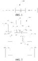
- the transmission power output part 22a includes an output shaft 24, and a driven gear 26 mounted on the output shaft 24 and configured to mesh with the driving gear 25 on the input shaft.
- the driven gears 26 are configured to mesh with the driving gears 25 on the input shafts respectively.
- the number of the driven gears 26 may be the same as that of the input shafts.
- the two driven gears 26 may be configured to mesh with the driving gears 25 on the two input shafts to transmit the power, so as to make the two pairs of gears form two gears for power transmitting.
- the power transmission system 100 in this embodiment may have at least the following operating conditions: a pure electric vehicle (EV) operating condition of the third motor generator 43, a pure EV four-wheel drive operating condition, a parallel operating condition, a series operating condition, and a braking/decelerating feedback operating condition.
- a pure electric vehicle (EV) operating condition of the third motor generator 43 a pure electric vehicle four-wheel drive operating condition, a parallel operating condition, a series operating condition, and a braking/decelerating feedback operating condition.
- This operating condition has the advantages of having better dynamic performance than a single-motor drive, and having better economic efficiency and lower noise than a hybrid drive.
- a typical application highlighting the advantages of this operating condition is traffic congestion at a steep slope (mountain road).
- a pure EV four-wheel drive vehicle has better acceleration performance, gradeability, handling performance and off-road capability. Since two second motor generators 42 and two third motor generators 43 drive four wheels independently, the wheels may obtain different torques and rotating speeds, to achieve the individual control on the four wheels, thus maximizing the dynamic performance, operating stability and off-road performance. Furthermore, when torques in different directions are applied to the left and right wheels by corresponding motor generators, the in-situ steering of the vehicle may be realized.
- This operating condition is a parallel operating condition.
- the dual clutch 31 is in an engaged state
- the synchronizer 6 is in an engaged state
- the engine unit 1 and the first motor generator 41 transfer the power to the driving gear 51 of the final drive via the shift gear set and the synchronizer 6, and the driving gear 51 of the final drive transfers the power to the front wheels 210 via the differential 54
- two second motor generators 42 transfer the power to the corresponding front wheels 210
- two third motor generators 43 transfer the power to the corresponding rear wheels 220.
- This operating condition is mainly applicable to a situation where a load is the largest, for example, during quick acceleration, or climbing steep slopes.
- This operating condition is a series operating condition.
- the dual clutch 31 is in an engaged state
- the synchronizer 6 is in a disengaged state
- the engine unit 1 drives the first motor generator 41 via the dual clutch 31 and the shift gear set to generate electricity
- the second motor generators 42 are configured to drive the front wheels 210 respectively
- the third motor generators 43 are configured to drive the rear wheels 220 respectively.
- This operating condition is mainly applicable to a situation where a load is medium and an electric quantity of a battery is small.
- This operating condition has the advantages that, since the second motor generator 42 and the third motor generator 43 brake four wheels respectively during the decelerating or braking, whether the vehicle is turning or moving straightly, the power of each wheel may be fully absorbed, in the premise of ensuring the braking force and stability of the vehicle, thus maximizing the energy feedback. Moreover, because of the disengagement of the synchronizer 6, while the four motor generators brake the four wheels respectively, the engine unit 1 and the first motor generator 41 may continue generating electricity, so as to enable a stable electricity generation state, avoid frequent switching, and extend the life of components.
- the second motor generators 42 and the third motor generators 43 may respond to the needs of the driver to increase the torque, such that the vehicle is accelerated, unlike a vehicle in the related art, the vehicle needs not to be accelerated only when the synchronizer 6 is in an engaged state.
- the torque compensation in advance may greatly shorten the torque response time and improve the instantaneous acceleration performance of the vehicle.
- the engine unit 1 and the first motor generator 41 may be kept generating electricity, under the braking operating condition and the series operating condition.
- the torque compensation in advance may greatly shorten the motor braking response time and increase the feedback electric quantity.
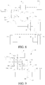
- the power transmission system 100 in this embodiment differs from the power transmission system 100 shown in Fig. 2 in the arrangement of the third motor generators 43.
- each third motor generator 43 drives a corresponding rear wheel 220 via one second speed changing mechanism 72.
- Other parts in this embodiment are substantially the same as those in the power transmission system 100 in the embodiment shown in Fig. 2 , so the detailed description thereof will be omitted here.
- the specific operating conditions of the power transmission system 100 in this embodiment are substantially the same as those of the power transmission system 100 in the embodiment shown in Fig. 2 , except that the power transfer between the third motor generators 43 and the corresponding rear wheels 220 is performed via the second speed changing mechanism 72, which will not be detailed here.
- the differential function of the rear wheels 220 may not be realized by means of only one motor and one speed changing mechanism, however, it would be appreciated that a differential integrally formed with the first speed changing mechanism 71 may be added to realize the differential rotation of the two rear wheels 220.
- the power transmission system 100 in this embodiment differs from the power transmission system 100 shown in Fig. 2 in the arrangement of the second motor generators 42.
- the second motor generators 42 are disposed at two sides of the differential 54 back to back respectively.
- Other parts in this embodiment are substantially the same as those in the power transmission system 100 in the embodiment shown in Fig. 2 , so the detailed description thereof will be omitted here.
- the specific operating conditions of the power transmission system 100 in this embodiment are substantially the same as those of the power transmission system 100 in the embodiment shown in Fig. 2 , which will not be detailed here.
- the power transmission system 100 in this embodiment differs from the power transmission system 100 shown in Fig. 5 in the arrangement of the third motor generators 43.
- each third motor generator 43 drives a corresponding rear wheel 220 via one second speed changing mechanism 72.
- Other parts in this embodiment are substantially the same as those in the power transmission system 100 in the embodiment shown in Fig. 2 , so the detailed description thereof will be omitted here.
- the specific operating conditions of the power transmission system 100 in this embodiment are substantially the same as those of the power transmission system 100 in the embodiment shown in Fig. 2 , which will not be detailed here.
- the power transmission system 100 in this embodiment differs from the power transmission system 100 shown in Fig. 5 in the arrangement of the third motor generators 43.
- one third motor generator 43 is provided and drives the rear wheels 220 via one first speed changing mechanism 71.
- Other parts in this embodiment are substantially the same as those in the power transmission system 100 in the embodiment shown in Fig. 5 , so the detailed description thereof will be omitted here.
- the specific operating conditions of the power transmission system 100 in this embodiment are substantially the same as those of the power transmission system 100 in the embodiment shown in Fig.
- the differential function of the rear wheels 220 may not be realized by means of only one motor and one speed changing mechanism, however, it would be appreciated that a differential integrally formed with the first speed changing mechanism 71 may be added to realize the differential rotation of the two rear wheels 220.
- the power transmission system 100 in this embodiment differs from the power transmission system 100 shown in Fig. 2 in the type of the clutch as well as the number of the input shafts, the driving gears 25 and the driven gears 26.
- the clutch is a triple clutch 32, three input shafts are provided, and correspondingly three pairs of driving gears 25 and driven gears 26 are provided.
- Other parts in this embodiment are substantially the same as those in the power transmission system 100 in the embodiment shown in Fig. 2 , so the detailed description thereof will be omitted here.
- the power transmission system 100 in this embodiment differs from the power transmission system 100 shown in Fig. 2 in that the third motor generators 43 in the embodiment shown in Fig. 2 are eliminated, and the power transmission system 100 in this embodiment is operable in a two-wheel drive mode.
- the power transmission system 100 in this embodiment may have at least the following operating conditions.
- This operating condition is a pure EV operating condition of the second motor generator 42.
- the dual clutch 31 is in a disengaged state
- the synchronizer 6 is in a disengaged state
- the engine unit 1 and the first motor generator 41 do not operate
- the second motor generators 42 drive the front wheels 210 directly.
- This operating condition is mainly applicable to a situation where a load is small and an electric quantity of a battery is large, for example, during uniform motions or under urban operating conditions.
- This operating condition has the advantages that, since the second motor generators 42 directly drive the front wheels 210, the transmission chain is the shortest, and operating components are the fewest, thus achieving maximum transmission efficiency and minimum noise. Moreover, since the second motor generators 42 independently drive the left front wheel 210 and the right front wheel 210 respectively, an electronic differential function may be achieved, thus increasing the handling stability and reducing the amount of tire wear.
- This operating condition is a pure EV operating condition of three motors.
- the dual clutch 31 is in a disengaged state, the synchronizer 6 is in an engaged state, the engine unit 1 does not operate, the first motor generator 41 transfers the power to the driving gear 51 of the final drive via the shift gear set and the synchronizer 6, and the driving gear 51 of the final drive evenly distributes the power to the left and right front wheels 210 via the differential 54, while the second motor generators 42 directly drive the left and right front wheels 210.
- This operating condition is mainly applicable to a situation where a load is large and an electric quantity of a battery is large, for example, during acceleration, climbing, overtaking, or high-speed running.
- This operating condition has the advantages of having better dynamic performance than a single-motor drive, and having better economic efficiency and lower noise than a hybrid drive.
- a typical application highlighting the advantages of this operating condition is traffic congestion at a steep slope (mountain road).
- This operating condition is a parallel operating condition.
- the dual clutch 31 is in a disengaged state
- the synchronizer 6 is in an engaged state
- the engine unit 1 and the first motor generator 41 transfer the power to the driving gear 51 of the final drive via the shift gear set and the synchronizer 6
- the driving gear 51 of the final drive evenly distributes the power to the left and right front wheels via the differential 54
- the second motor generators 42 directly drive the left and right front wheels.
- This operating condition is mainly applicable to a situation where a load is the largest, for example, during quick acceleration, or climbing steep slopes.
- This operating condition has the advantages that three motors and the engine unit 1 drive the vehicle simultaneously, thus maximizing the dynamic performance.
- This operating condition is a series operating condition.
- the dual clutch 31 is in an engaged state
- the synchronizer 6 is in a disengaged state
- the engine unit 1 drives the first motor generator 41 via the dual clutch 31 and the shift gear set to generate electricity
- the second motor generators 42 directly drive the wheels.
- This operating condition is mainly applicable to a situation where a load is medium and an electric quantity of a battery is small.
- This operating condition has the advantages that, since the second motor generators 42 directly drive the wheels, the transmission chain is the shortest, and operating components are the fewest, thus achieving maximum transmission efficiency and minimum noise.
- the first motor generator 41 may keep the engine unit 1 running in an optimal economic region through torque and rotating speed adjustment, thus reducing fuel consumption during the electricity generation.
- the second motor generators 42 independently drive the left front wheel and the right front wheel respectively, an electronic differential function may be achieved, thus increasing the handling stability and reducing the amount of tire wear.
- This operating condition is a braking/decelerating feedback operating condition.
- the dual clutch 31 is in an engaged state, the synchronizer 6 is in a disengaged state, the engine unit 1 drives the first motor generator 41 to generate electricity, and the second motor generator 42 directly brakes the wheels and generates electricity.
- This operating condition is mainly used for braking or decelerating the vehicle.
- This operating condition has the advantages that, since the second motor generator 42 brake two wheels respectively during the decelerating or braking of the vehicle, the braking energy may be absorbed to the largest extent and converted into electric energy, and the engine unit 1 and the first motor generator 41 may continue generating electricity, to enable a stable electricity generation state and avoid frequent switching.
- the power transmission system may switch from the fourth operating condition to the third operating condition.
- the first motor generator 41 may adjust the rotating speed of the output shaft 24 with the rotating speed of the driving gear 51 of the final drive as a target value through the rotating speed control, so as to match the rotating speed of the output shaft 24 with the rotating speed of the driving gear 51 of the final drive as far as possible, thus facilitating the engagement of the synchronizer 6.
- the second motor generators 42 may respond to the needs of the driver to increase the torque, such that the vehicle is accelerated, unlike a vehicle in the related art, the vehicle does not require the synchronizer 6 to be in an engaged state in order to be accelerated.
- the torque compensation in advance may greatly shorten the torque response time and improve the instantaneous acceleration performance of the vehicle.
- the switching from the fourth operating condition to the fifth operating condition will be described as follows.
- the power transmission system 100 may switch from the fourth operating condition to the fifth operating condition.
- the second motor generators 42 may meet the braking feedback requirements, and the feedback of the first motor generator 41 is not needed.
- the second motor generators 42 may instantly respond to the needs of the driver to brake the wheels and feed back the electric quantity, unlike a vehicle in the related art, the vehicle does not require the synchronizer 6 to be in an engaged state to feed back the electric quantity.
- the power transmission system 100 in this embodiment differs from the power transmission system 100 shown in Fig. 9 in the arrangement of the second motor generators 42.
- the second motor generators 42 are disposed at two sides of the differential 54 back to back respectively.
- Other parts in this embodiment are substantially the same as those in the power transmission system 100 in the embodiment shown in Fig. 9 , so the detailed description thereof will be omitted here.
- the power transmission system 100 in this embodiment differs from the power transmission system 100 shown in Fig. 9 in the arrangement of the second motor generators 42.
- two second motor generators 42 are provided, and each second motor generator 42 drives a corresponding rear wheel 220 via one fourth speed changing mechanism 74.
- Other parts in this embodiment are substantially the same as those in the power transmission system 100 in the embodiment shown in Fig. 9 , so the detailed description thereof will be omitted here.
- the power transmission system 100 in this embodiment may have at least the following operating conditions.
- This operating condition is a pure EV four-wheel drive operating condition.
- the dual clutch 31 is in a disengaged state, the synchronizer 6 is in an engaged state, the engine unit 1 does not operate, the first motor generator 41 drives the front wheels respectively, and the second motor generators 42 drive the rear wheels respectively.
- This operating condition is mainly applicable to a situation where a load is large and an electric quantity of a battery is large, for example, during acceleration, climbing, overtaking, or high-speed running.
- This operating condition has the advantages of having better dynamic performance than a single-motor drive, and having better economic efficiency and lower noise than a hybrid drive.
- a typical application highlighting the advantages of this operating condition is traffic congestion at a steep slope (mountain road).
- a pure EV four-wheel drive vehicle has better acceleration performance, gradeability, handling performance and off-road capability.
- the second motor generators 42 independently drive the left rear wheel and the right rear wheel respectively, an electronic differential function may be achieved, thus increasing the handling stability and reducing the amount of tire wear.
- This operating condition is a parallel operating condition.
- the dual clutch 31 is in a disengaged state
- the synchronizer 6 is in an engaged state
- the engine unit 1 and the first motor generator 41 drive the front wheels 210 simultaneously
- the second motor generators 42 drive the rear wheels respectively.
- This operating condition is mainly applicable to a situation where a load is the largest, for example, during quick acceleration, or climbing steep slopes.
- This operating condition has the advantages that two motor generators and the engine unit drive the vehicle simultaneously, thus maximizing the dynamic performance.
- a HEV four-wheel drive vehicle has better acceleration performance, gradeability, handling performance and off-road capability.
- the second motor generators 42 independently drive the left rear wheel and the right rear wheel respectively, an electronic differential function may be achieved, thus increasing the handling stability and reducing the amount of tire wear.
- This operating condition is a series operating condition.
- the dual clutch 31 is in an engaged state
- the synchronizer 6 is in a disengaged state
- the engine unit 1 drives the first motor generator 41 to generate electricity
- the second motor generators 42 drive the rear wheels respectively.
- This operating condition is mainly applicable to a situation where a load is medium and an electric quantity of a battery is small.
- This operating condition has the advantages that, since the two second motor generators independently drive the left rear wheel and the right rear wheel respectively, an electronic differential function may be achieved, thus increasing the handling stability and reducing the amount of tire wear.
- the vehicle under the series operating condition has better acceleration performance, gradeability, and steering capability.
- the first motor generator 41 may keep the engine unit 1 running in an optimal economic region through torque and rotating speed adjustment, thus reducing fuel consumption during the electricity generation.
- This operating condition is a braking/decelerating feedback operating condition.
- the dual clutch 31 is in a disengaged state, the synchronizer 6 is in an engaged state, the engine unit does not operate, and the first motor generator and the second motor generators brake the vehicle and generate electricity simultaneously.
- This operating condition has the advantages that, since three motors brake the vehicle simultaneously during the decelerating or braking of the vehicle, the braking energy may be absorbed to the largest extent and converted into electric energy.
- the disengagement of the dual clutch the braking of the vehicle by the friction torque of the engine unit may be eliminated, so that more power is left to be absorbed by the motor.
- the braking force may be distributed to front and rear motors in the premise of ensuring the braking force of the vehicle, and more electric energy may be fed back compared to a front-wheel drive vehicle or a rear-wheel drive vehicle.
- two second motor generators may control the braking force independently, thus improving the handling stability of the vehicle during braking when turning, and further increasing the feedback energy.
- the operating conditions of the power transmission system 100 in this embodiment may be switched, and typical switching between operating conditions is switching from the fourth operating condition to the third operating condition, or switching from the fourth operating condition to the fifth operating condition.
- the switching between the operating conditions of the power transmission system 100 in this embodiment is similar to that in the above embodiments, so the detailed description thereof will be omitted here.
- the power transmission system 100 in this embodiment differs from the power transmission system 100 shown in Fig. 9 in the arrangement of the second motor generators 42.
- one second motor generators 42 is provided, and the second motor generator 42 drives the rear wheels 220 via one third speed changing mechanism 73.
- Other parts in this embodiment are substantially the same as those in the power transmission system 100 in the embodiment shown in Fig. 9 , so the detailed description thereof will be omitted here.
- the second motor generator 42 may be used to drive the vehicle separately.
- the dual clutch 31 and the synchronizer 6 are in a disengaged state.
- This operating condition is mainly applicable to a situation where a load is small and an electric quantity of a battery is large, for example, during uniform motions or under urban operating conditions.
- This operating condition has the advantages that, since the second motor generators 42 directly drive the rear wheels 220 via the third speed changing mechanism 73, compared to a front-wheel drive vehicle, the vehicle in this embodiment has better acceleration performance, gradeability and steering capability.
- the synchronizer 6 In a front-wheel drive part, the synchronizer 6 is in a disengaged state, so there is no mechanical loss in the front-wheel drive part, thus reducing the energy consumption of the vehicle.
- a differential integrally formed with the third speed changing mechanism 73 may also be added.
- the power transmission system 100 may also have a pure EV four-wheel drive operating condition.
- the dual clutch 31 is in a disengaged state
- the synchronizer 6 is in an engaged state
- the engine unit 1 does not operate
- the first motor generator 41 drives the front wheels 210 respectively
- the second motor generator 42 drives the rear wheels 220 respectively.
- This operating condition is mainly applicable to a situation where a load is large and an electric quantity of a battery is large, for example, during acceleration, climbing, overtaking, or high-speed running.
- This operating condition has better dynamic performance than a single-motor drive, and has better economic efficiency and lower noise than a hybrid drive.
- a typical application highlighting the advantages of this operating condition is traffic congestion at a steep slope (mountain road).
- a pure EV four-wheel drive vehicle has better acceleration performance, gradeability, handling performance and off-road capability.
- the power transmission system may also have a parallel operating condition.
- the dual clutch 31 is in an engaged state
- the synchronizer 6 is in an engaged state
- the engine unit 1 and the first motor generator 41 drive the front wheels 210 simultaneously
- the second motor generator 42 drives the rear wheels 220.
- This operating condition is mainly applicable to a situation where a load is the largest, for example, during quick acceleration, or climbing steep slopes.
- This operating condition has the advantages that two motors and the engine unit 1 drive the vehicle simultaneously, thus maximizing the dynamic performance.
- a HEV four-wheel drive vehicle has better acceleration performance, gradeability, handling performance and off-road capability.
- the power transmission system may also have a series operating condition.
- the dual clutch 31 is in an engaged state
- the synchronizer 6 is in a disengaged state
- the engine unit 1 drives the first motor generator 41 to generate electricity
- the second motor generator drives the rear wheels.
- This operating condition is mainly applicable to a situation where a load is medium and an electric quantity of a battery is small.
- This operating condition has the advantages that the second motor generator 42 drives the rear wheels, and compared to a front-wheel drive vehicle, the vehicle under the series operating condition has better acceleration performance, gradeability and steering capability.
- the first motor generator 41 may keep the engine unit 1 running in an optimal economic region through torque and rotating speed adjustment, thus reducing fuel consumption during the electricity generation.
- the braking force may be distributed to front and rear motors in the premise of ensuring the braking force of the vehicle, and more electric energy may be fed back compared to a front-wheel drive vehicle or a rear-wheel drive vehicle.
- the operating conditions of the power transmission system 100 in this embodiment may be switched, and typical switching between operating conditions is switching from the fourth operating condition to the third operating condition, or switching from the fourth operating condition to the fifth operating condition.
- the switching between the operating conditions of the power transmission system 100 in this embodiment is similar to that in the above embodiments, so the detailed description thereof will be omitted here.
- the power transmission system 100 in this embodiment differs from the power transmission system 100 shown in Fig. 9 in the arrangement of the second motor generators 42.
- two second motor generators 42 are provided and are wheel-side motors, and each second motor generator 42 drives a corresponding rear wheel 220.
- Other parts in this embodiment are substantially the same as those in the power transmission system 100 in the embodiment shown in Fig. 9 , so the detailed description thereof will be omitted here.
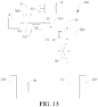
- the engine unit 1 is coupled with the input terminal 313 of the dual clutch 31, the first output terminal 311 of the dual clutch 31 is coupled with the first input shaft 21, the second output terminal 312 of the dual clutch 31 is coupled with the second input shaft 22, and the second input shaft 22 is coaxially fitted over the first input shaft 21.
- Each of the first input shaft 21 and the second input shaft 22 is provided with one driving gear 25 by fixing, the double-linked gear structure 26 (i.e. a driven gear) is freely fitted over the output shaft 24, the first gear part 261 of the double-linked gear structure 26 is configured to mesh with the driving gear 25 on the first input shaft 21, and the second gear part 262 of the double-linked gear structure 26 is configured to mesh with the driving gear 25 on the second input shaft 22.
- the double-linked gear structure 26 i.e. a driven gear
- a first intermediate shaft gear 451 and a second intermediate shaft gear 452 are fixed on the intermediate shaft 45.
- the first intermediate shaft gear 451 is configured to mesh with the driving gear 25 on the second input shaft 22. Indirect power transmitting between the output terminal of the first motor generator 41 and the second intermediate shaft gear 452 via an intermediate idler 44 is performed.
- the synchronizer 6 is disposed on the output shaft 24 and configured to engage with the double-linked gear structure 26.
- the driving gear 51 of the final drive is fixed on the output shaft 24.
- the driving gear 51 of the final drive is configured to externally mesh with the driven gear 53 of the final drive, and the driven gear 53 of the final drive may be fixed on a shell of the differential 54, so as to transfer the power to the differential 54.
- the differential 54 distributes the power and adaptively transfers the distributed power to half axles at two sides of the vehicle, so as to drive the wheels 200.
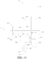
- a first intermediate shaft gear 451 and a second intermediate shaft gear 452 are fixed on the intermediate shaft 45.
- the first intermediate shaft gear 451 is configured to mesh with the driving gear 25 on the second input shaft 22.
- the output terminal of the first motor generator 41 is configured to directly mesh with the second intermediate shaft gear 452 for power transmitting.
- the power transmission system 100 may further include the second motor generator 42 and the third motor generator 43 or only include the third motor generator 43 (not shown in Figs. 14-19 ), and the arrangement of the second motor generator 42 and the third motor generator 43 may be the same as that in Figs. 2-13 , for example, being in a wheel-side form, or being disposed at two sides of the differential back to back.
- the driving gear 51 of the final drive of the power transmission system 100 shown in Figs. 14-19 may be configured to drive the front wheels 210, and the rear-wheel drive may be the same as that shown in Fig. 12 , i.e. the rear wheels 220 are driven by one second motor generator 42 and one reducing mechanism.
- embodiments of the present disclosure further provide a vehicle including the abovementioned power transmission system 100.
- other components e.g., a driving system, a steering system, and a braking system
- a driving system e.g., a steering system, and a braking system
- a condition for entering cruise control is determined. When all preset cruise control conditions are met, the vehicle enters cruise.
- the EV mode cruise strategy and the HEV mode cruise strategy are respectively provided for different operating modes of the vehicle, so as to meet cruise requirements of an automobile of a user in different operating modes.
- a control method for the EV cruise mode and a control method for the HEV cruise mode are respectively described below by using two specific embodiments.
- the required torque Tc of the vehicle is calculated, so that in a low-electric quantity strategy, if the current SOC of the power battery of the vehicle is less than the second electric quantity threshold value SOC2 and the output torque upper limit of the engine unit is greater than the required torque, the engine unit is controlled to output the required torque.
- the engine unit is controlled to drive the first motor generator to generate electricity. If the output torque upper limit of the engine unit is less than the required torque, the second motor generator and the first motor generator are controlled to successively perform torque compensation output.
- the engine unit performs output according to the output torque upper limit Te of the engine unit, the second motor generator and the first motor generator successively compensate for the remaining torque, and the output torque of the second motor generator and the first motor generator is Tc-Te.
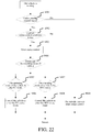
- the engine unit when the vehicle enters the HEV cruise mode, if it is determined that the current SOC of the power battery of the vehicle is less than the second electric quantity threshold value SOC2, and when the output torque upper limit Te of the engine unit is less than required torque Tc, the engine unit is controlled to output the output torque upper limit Te of the engine unit, and according to the method shown in Fig. 4 in some embodiments of the present disclosure, the second motor generator is first controlled to perform torque compensation output, and when the second motor generator also cannot fully compensate for the remaining torque, the first motor generator is then controlled to perform torque compensation output.
- S1112 Compare the required torque Tc of the current cruise mode of the vehicle with the output torque upper limit Te of the engine unit, to determine the range of the required torque Tc of the current cruise mode.
- the engine unit outputs the torque Tc, and the first motor and the second motor do not perform output. That is, after the vehicle enters the HEV cruise mode, if it is determined that the current SOC of the power battery of the vehicle is greater than or equal to the second electric quantity threshold value SOC2 and is less than or equal to the third electric quantity threshold value SOC3, and when the output torque upper limit Te of the engine unit is greater than or equal to the required torque Tc of the vehicle, the engine unit is controlled to output a torque according to the cruise required torque Tc of the vehicle.
- Step S1115 When it is determined that the output torque upper limit Te of the engine unit is less than the required torque Tc, perform Step S1116.
- S1119 Compare the required torque Tc of the current cruise mode of the vehicle with the output torque upper limit Tm2 of the second motor generator, and determine the range of the required torque Tc of the current cruise mode.
- the torque output by the second motor generator is the required torque Tc. That is, after the vehicle enters the HEV cruise mode, if it is determined that the current SOC of the power battery of the vehicle is greater than the third electric quantity threshold value SOC3, and when the output torque upper limit Tm2 of the second motor generator is greater than or equal to the required torque Tc, the second motor generator is controlled to output a torque according to the required cruise torque Tc of the vehicle.
- the second motor generator performs output according to the output torque upper limit Tm2 of the second motor generator, and the engine unit and the first motor generator successively compensate for the remaining torque, where the output torque of the engine unit and the first motor generator is Tc-Tm2.
- the second motor generator when the vehicle enters the HEV cruise mode, if it is determined that the current SOC of the power battery of the vehicle is greater than the third electric quantity threshold value SOC3, and when the output torque upper limit Tm2 of the second motor generator is less than the required torque Tc, the second motor generator is controlled to output the output torque upper limit Tm2 of the second motor generator, the engine unit is first controlled to perform torque compensation output, and when the engine unit also cannot fully compensate for the remaining torque, the first motor generator is then controlled to perform torque compensation output.
- the electric quantity SOC of the battery is compared with the second electric quantity threshold value SOC2, the third electric quantity threshold value SOC3.
- the cruise control method for a HEV mode is correspondingly classified into the low-electric quantity strategy, the intermediate-electric quantity strategy, and the high-electric quantity strategy, and different power distribution strategies for the engine unit, the first motor generator, and the second motor generator are separately provided for the foregoing three strategies.
- the engine unit first performs driving, and within the economic region, the engine unit is controlled to drive the first motor generator to generate electricity.
- a method for determining to exit cruise in the foregoing cruise control method for a vehicle specifically includes the following steps: S1201: Determine whether a cruise main switch or a cruise cancel button is triggered, that is, is pressed. If yes, perform Step S1214; or if not, perform Step S1202.
- Step S1202 Determine whether the current cruise speed V is less than the preset lower limit value Vmin. If yes, perform Step S1214; or if not, perform Step S1203.
- Step S1203 Determine whether the braking pedal is depressed. If yes, perform Step S1214; or if not, perform Step S1204.
- Step S1204 Determine whether the current gear is changed to a gear other than gear D. If yes, perform Step S1214; or if not, perform Step S1205.
- Step S1205 Determine whether the cruise control switch is in an abnormal state. If yes, perform Step S314; or if not, perform Step S1206.
- Step S1206 Determine whether the speed signal is in an abnormal state. If yes, perform Step S1214; or if not, perform Step S1207.
- Step S1207 Determine whether the braking signal is in an abnormal state. If yes, perform Step S1214; or if not, perform Step S1208.
- Step S1209 Determine whether the EPB requests to cancel cruise. If yes, perform Step S1214; or if not, perform Step S1210.
- Step S1210 Determine whether the ESP works. If yes, perform Step S1214; or if not, perform Step S1211.
- Step S1211 Determine whether the EPB/ESP fails. If yes, perform Step S1214; or if not, perform Step S1212.
- Step S1201 to Step S1212 If during the cruise process, none of the conditions in Step S1201 to Step S1212 is met, continue with the cruise, and determining is performed cyclically from Step S1201 to Step S1212 during the cruise.
- Step S1201 to Step S1212 the vehicle is controlled to exit the cruise mode.
- the vehicle exits cruise control, and the cruise mode cannot automatically restore that is, after the vehicle exits cruise, if the user does not enter a cruise operation again, the vehicle cannot automatically restore the cruise mode.
- the vehicle may cruise in operating modes: the EV mode and the HEV mode, and cruise control strategies in the two operating modes are provided.
- the cruise control strategies are, for example, a control strategy for an EV cruise mode in which the first motor generator and the second motor generator are used to perform torque output to perform cruise and a control strategy for a HEV cruise mode in which the engine unit, the first motor generator, and the second motor generator jointly perform output to perform cruise.
- the cruise control strategy for the EV mode cannot meet a cruise requirement, the engine unit is automatically started, and the vehicle is switched to the cruise control strategy for the HEV mode.
- the control method for entering cruise and exiting cruise is added. Therefore, safety of a user can be ensured while a normal cruise function of the vehicle is ensured.
- a user can control the vehicle to cruise in an EV mode and a HEV mode, so that a pure EV cruise requirement of the user can be met, and fuel consumption can be reduced. It can also be ensured that when the pure EV cannot meet the cruise requirement, the vehicle automatically switches to a cruise control strategy for a HEV mode, so that it is ensured that the user can perform cruise driving continuously and reliably.
- the cruise control strategies in two different operating modes meet different driving requirements of the user, so as to implement combination of selection of a driving mode and an automatic cruise function for running at a constant speed, and bring convenience to driving while fuel consumption can be reduced, making it more economical and environmentally friendly.
- the transmission unit 2a is adapted to selectively be coupled with the engine unit 1.
- the first motor generator 41 is coupled with the transmission unit 2a.
- the output unit 5 is configured to transmit the power transmitted by the transmission unit 2a to at least one of front and rear wheels of the vehicle.
- the power switching device e.g., the synchronizer 6) is adapted to enable or interrupt a transmitting of power between the transmission unit 2a and the output unit 5.
- the second motor generator 42 is configured to drive the front wheels or rear wheels.
- the power battery 300 is connected to the first motor generator 41 and/or the second motor generator 42 to supply power to the first motor generator 41 and/or the second motor generator 42.
- the controller 500 determines whether the vehicle meets a preset cruise control condition, and when the vehicle meets the preset cruise control condition, the controller 500 controls the vehicle according to the current operating mode of the vehicle to enter a corresponding cruise mode, where when the current operating mode of the vehicle is an EV mode, the controller 500 controls the vehicle to enter an EV cruise mode, and when the current operating mode of the vehicle is a HEV mode, the controller 500 controls the vehicle to enter a HEV cruise mode.
- the controller 500 controls the vehicle not to enter a corresponding cruise mode.
- the vehicle is in the cruise mode, if any condition of the preset cruise control conditions is not met or when a signal for the vehicle to exit cruise control is detected, the vehicle is controlled to exit the corresponding cruise mode. Therefore, safety of a user can be further ensured while it is ensured that the vehicle maintains a normal cruise function.
- the controller 500 controls the engine unit 1 to start, and controls the vehicle to enter the HEV cruise mode.
Landscapes
- Engineering & Computer Science (AREA)
- Transportation (AREA)
- Mechanical Engineering (AREA)
- Chemical & Material Sciences (AREA)
- Combustion & Propulsion (AREA)
- Automation & Control Theory (AREA)
- Human Computer Interaction (AREA)
- Electric Propulsion And Braking For Vehicles (AREA)
- Hybrid Electric Vehicles (AREA)
Description
- The present invention relates to the technical field of vehicles, and more particularly to a cruise control method for a vehicle and a vehicle.
- To reduce energy consumption, development and utilization of energy-efficient vehicles have become a trend. As an energy-efficient vehicle, a vehicle is driven by at least one of an engine and a motor and has various operation modes, and consequently may operate with improved transmission efficiency and fuel economic efficiency.
- However, in the related art, the power transmission system in the vehicle is generally complex in structure, bulky, low in transmission efficiency, and complicated in control strategy. For example, a plurality of gear shift actuating components needs to be controlled simultaneously during the gear shifting or mode switching. An improvement needs to be made.
-
EP2133252A1 discloses a vehicle controlling apparatus including a motor travel selection detecting unit for detecting that the driver has selected the motor travel allowing the vehicle to travel by motive power of the rotating electric machine, and a cruise travel selection detection unit for detecting that the driver has selected the cruise travel in which either one of the speed of the vehicle and the distance from another vehicle is automatically maintained at a predetermined value, wherein the vehicle is controlled with the cruise travel having priority over the motor travel, when it is detected that the driver has selected both the motor travel and the cruise travel. -
US2013/0096749A1 discloses a method for controlling a two electric tandem motor apparatus for use in a hybrid electric drive vehicle. - The invention relates to a method and a vehicle having the features according to the respective independent claim. Preferred embodiments are subject-matters of the dependent claims.
- The present invention seeks to solve at least one of the problems existing in the related art to at least some extent. The present invention provides a cruise control method for a vehicle, which can overcome deficiencies in the prior art, and implement combination of selection of a driving mode and an automatic cruise function for running at a constant speed, so as to meet different driving requirements of drivers, and bring convenience to driving while fuel consumption can be reduced.
- Another objective of the present invention is to provide a vehicle.
- To achieve the foregoing objectives, an aspect of the present invention provides a cruise control method according to
claim 1 for a vehicle. The vehicle includes an engine unit, a transmission unit adapted to selectively couple with the engine unit and also configured to transmit the power generated by the engine unit, a first motor generator coupled with the transmission unit, an output unit, a power switching device, a second motor generator configured to drive front wheels and/or rear wheels, and a power battery supplying power to the first motor generator and/or the second motor generator. The output unit is configured to transmit the power transmitted by the transmission unit to at least one of the front and rear wheels of the vehicle, and the power switching device is adapted to enable or interrupt a transmitting of power between the transmission unit and the output unit. The cruise control method includes the following steps: when a signal for the vehicle to enter cruise control is detected, determining whether the vehicle meets a preset cruise control condition; and if the vehicle meets the preset cruise control condition, controlling the vehicle according to a current operating mode of the vehicle to enter a corresponding cruise mode, where when the current operating mode of the vehicle is an electric vehicle (EV) mode, the vehicle is controlled to enter an EV cruise mode, and when the current operating mode of the vehicle is a HEV mode, the vehicle is controlled to enter a HEV cruise mode. - According to the cruise control method for a vehicle in some embodiments of the present disclosure, combination of selection of a driving mode and an automatic cruise function for running at a constant speed is implemented, so as to meet different driving requirements of drivers, and bring convenience to driving while fuel consumption can be reduced, making it more economical and environmentally friendly. Moreover, power output by the engine unit and/or a first motor generator may be output to an output unit via a power switching device, and the output unit then outputs the power to at least one of front and rear wheels of the vehicle. Meanwhile, because of the provision of a second motor generator, the second motor generator may compensate for a torque for the front wheels or rear wheels, and may also cooperate with the engine unit and the first motor generator to drive the vehicle, thus increasing the number of operation modes of the vehicle, so that the vehicle may be better adapted to different operating conditions, thus achieving better fuel economic efficiency while reducing the emission of harmful gases.
- To achieve the foregoing objectives, the present invention provides a vehicle according to
claim 6, including: an engine unit; a transmission unit, where the transmission unit is adapted to selectively couple with the engine unit and also configured to transmit the power generated by the engine unit; a first motor generator, where the first motor generator is coupled with the transmission unit; an output unit, where the output unit is configured to transmit the power transmitted by the transmission unit to at least one of the front and rear wheels of the vehicle; a power switching device, where the power switching device is adapted to enable or interrupt a transmitting of power between the transmission unit and the output unit; a second motor generator, where the second motor generator is configured to drive the front wheel or the rear wheel; a power battery, where the power battery is connected to the first motor generator and/or the second motor generator to supply power to the first motor generator and/or the second motor generator; and a controller, where when a signal for the vehicle to enter cruise control is detected, the controller determines whether the vehicle meets a preset cruise control condition, and when the vehicle meets the preset cruise control condition, the controller controls the vehicle according to a current operating mode of the vehicle to enter a corresponding cruise mode, where when the current operating mode of the vehicle is an EV mode, the controller controls the vehicle to enter an EV cruise mode, and when the current operating mode of the vehicle is a HEV mode, the controller controls the vehicle to enter a HEV cruise mode. - According to the vehicle in some embodiments of the present disclosure, combination of selection of a driving mode and an automatic cruise function for running at a constant speed is implemented, so as to meet different driving requirements of drivers, and bring convenience to driving while fuel consumption can be reduced, making it more economical and environmentally friendly. Moreover, power output by the engine unit and/or a first motor generator may be output to an output unit via a power switching device, and the output unit then outputs the power to at least one of front and rear wheels of the vehicle. Meanwhile, because of the provision of a second motor generator, the second motor generator may compensate for a torque for the front wheels or rear wheels, and may also cooperate with the engine unit and the first motor generator to drive the vehicle, thus increasing the number of operation modes of the vehicle, so that the vehicle may be better adapted to different operating conditions, thus achieving better fuel economic efficiency while reducing the emission of harmful gases.
- Additional aspects and advantages of the present disclosure will be given in part in the following descriptions, become apparent in part from the following descriptions, or be learned from the practice of the present disclosure.
- These and other aspects and advantages of embodiments of the present disclosure will become apparent and more readily appreciated from the following descriptions made with reference to the drawings, in which:
-
Fig. 1 is a schematic diagram of a power transmission system according to an embodiment of the present disclosure; -
Fig. 2 is a schematic view of a power transmission system according to an embodiment of the present disclosure; -
Fig. 3 is a schematic view of a power transmission system according to another embodiment of the present disclosure; -
Fig. 4 is a schematic view of a power transmission system according to still another embodiment of the present disclosure; -
Fig. 5 is a schematic view of a power transmission system according to yet another embodiment of the present disclosure; -
Fig. 6 is a schematic view of a power transmission system according to yet another embodiment of the present disclosure; -
Fig. 7 is a schematic view of a power transmission system according to yet another embodiment of the present disclosure; -
Fig. 8 is a schematic view of a power transmission system according to yet another embodiment of the present disclosure; -
Fig. 9 is a schematic view of a power transmission system according to yet another embodiment of the present disclosure; -
Fig. 10 is a schematic view of a power transmission system according to yet another embodiment of the present disclosure; -
Fig. 11 is a schematic view of a power transmission system according to yet another embodiment of the present disclosure; -
Fig. 12 is a schematic view of a power transmission system according to yet another embodiment of the present disclosure; -
Fig. 13 is a schematic view of a power transmission system according to yet another embodiment of the present disclosure; -
Fig. 14 is a schematic view of a power transmission system according to yet another embodiment of the present disclosure; -
Fig. 15 is a schematic view of a power transmission system according to yet another embodiment of the present disclosure; -
Fig. 16 is a schematic view of a power transmission system according to yet another embodiment of the present disclosure; -
Fig. 17 is a schematic view of a power transmission system according to yet another embodiment of the present disclosure; -
Fig. 18 is a schematic view of a power transmission system according to yet another embodiment of the present disclosure; -
Fig. 19 is a schematic view of a power transmission system according to yet another embodiment of the present disclosure; -
Fig. 20 is a flowchart of a cruise control method for a vehicle according to an embodiment of the present disclosure; -
Fig. 21 is a flowchart of method for determining to enter cruise control in a cruise control method for a vehicle according to an embodiment of the present disclosure; -
Fig. 22 is a flowchart of a cruise control method for a vehicle according to an embodiment of the present disclosure; -
Fig. 23 is a flowchart of a cruise control method for a vehicle when a vehicle enters an EV cruise mode according to an embodiment of the present disclosure; -
Fig. 24 is a flowchart of a cruise control method for a vehicle when a vehicle enters a HEV cruise mode according to another embodiment of the present disclosure; -
Fig. 25 is a flowchart of a method for determining to exit cruise control in a cruise control method for a vehicle according to still another embodiment of the present disclosure; and -
Fig. 26 is a schematic view of a vehicle according to an embodiment of the present disclosure. - Reference will be made in detail to embodiments of the present disclosure. The embodiments described herein with reference to drawings are explanatory, illustrative, and used to generally understand the present disclosure. The embodiments shall not be construed to limit the present disclosure. The same or similar elements and the elements having same or similar functions are denoted by like reference numerals throughout the descriptions.
- In the specification, unless specified or limited otherwise, relative terms such as "central", "longitudinal", "lateral", "front", "rear", "right", "left", "inner", "outer", "lower", "upper", "horizontal", "vertical", "above", "below", "up", "top", "bottom" as well as derivative thereof (e.g., "horizontally", "downwardly", "upwardly", etc.) should be construed to refer to the orientation as then described or as shown in the drawings under discussion. These relative terms are for convenience of description.
- In the description of the present disclosure, it should be understood that, unless specified or limited otherwise, the terms "mounted," "connected," and "coupled" and variations thereof are used broadly and encompass such as mechanical or electrical mountings, connections and couplings, also can be inner mountings, connections and couplings of two components, and further can be direct and indirect mountings, connections, and couplings.
- In addition, terms such as "first" and "second" are used herein for purposes of description and are not intended to indicate or imply relative importance or significance or to imply the number of indicated technical features. Thus, the feature defined with "first" and "second" may comprise one or more of this feature. In the description of the present disclosure, "a plurality of' means two or more than two, unless specified otherwise.
- A
power transmission system 100 according to embodiments of the present disclosure will be described in detail below with reference toFigs. 1-19 . Thepower transmission system 100 is applicable to a vehicle, such as a hybrid vehicle with anengine unit 1 and a motor generator. - As shown in the figures, the
power transmission system 100 according to embodiments of the present disclosure may include anengine unit 1, atransmission unit 2a, afirst motor generator 41, asecond motor generator 42, anoutput unit 5, and a power switching device (e.g., asynchronizer 6, and a clutch 9). - The
transmission unit 2a is adapted to selectively be coupled with theengine unit 1. Theengine unit 1 may selectively output a power generated by theengine unit 1 to thetransmission unit 2a via theclutch 9 or the like. Alternatively, thetransmission unit 2a may also output, for example, a starting torque from thefirst motor generator 41 to theengine unit 1, so as to start theengine unit 1. In the context of the present disclosure, the phrase "thetransmission unit 2a is coupled with theengine unit 1" means that the power can be transferred between theengine unit 1 and thetransmission unit 2a directly or via other components, and the coupling between thetransmission unit 2a and theengine unit 1 is also referred to as a power coupling. - The
engine unit 1 generates energy by mixing liquid or gaseous fuel and air and then combusting the mixed fuel and air therein, and the energy is converted into mechanical energy. Theengine unit 1 of the vehicle may generally adopt a four-stroke gasoline or diesel engine. Theengine unit 1 may generally include a block, a crank-connecting rod mechanism, a valve mechanism, a supply system, an ignition system, a cooling system, a lubrication system and the like. - The block is an assembled body of individual mechanisms and systems of the
engine unit 1. The crank-connecting rod mechanism may convert the linear reciprocating motion of a piston into the rotary motion of a crankshaft, and output a drive force. The valve mechanism is configured to charge or discharge a gas at a predetermined time, so as to ensure the smooth performing of each cycle of theengine unit 1. The supply system may supply a mixture of oil and gas to a cylinder for combustion. The cooling system is configured to cool theengine unit 1, so as to ensure that the operating temperature of theengine unit 1 is within a suitable temperature range. The lubrication system is configured to lubricate individual motion pairs in theengine unit 1, so as to reduce the wear and energy loss. - It would be appreciated that the foregoing
engine unit 1 as well as specific structures and operation principles of individual sub-systems and sub-mechanisms of theengine unit 1 are well known to those skilled in the art, so the detailed description thereof will be omitted here for clarity purpose. - The
first motor generator 41 is coupled with thetransmission unit 2a. In other words, thefirst motor generator 41 cooperates with thetransmission unit 2a to transmit the power. That is, thefirst motor generator 41 may drive thetransmission unit 2a, while thetransmission unit 2a may drive thefirst motor generator 41. - For example, the
engine unit 1 may output at least a part of the power generated thus to thefirst motor generator 41 via thetransmission unit 2a, and thefirst motor generator 41 may generate electricity and convert mechanical energy into electric energy to be stored in an energy storage component such as a battery component. As another example, thefirst motor generator 41 may convert electric energy from the battery component into mechanical energy, and output the mechanical energy to theoutput unit 5 via thetransmission unit 2a to drive the vehicle. - The
first motor generator 41 is a motor having functions of both a motor and a generator. As used in the present disclosure, the term "motor generator" refers to a motor having functions of both a motor and a generator, unless specified otherwise. - The
output unit 5 is configured to transmit a power transmitted by thetransmission unit 2a to wheels 200 (e.g., one of front andrear wheels 210 and 220) of the vehicle. In short, theoutput unit 5 is adapted to output the power from thetransmission unit 2a. - The power switching device such as the
synchronizer 6 is adapted to enable or interrupt a power transmitting between theoutput unit 5 and thetransmission unit 2a. In other words, the power switching device may output the power output from thetransmission unit 2a to at least one of front andrear wheels output unit 5, or the power switching device may also disconnect thetransmission unit 2a from theoutput unit 5 and thetransmission unit 2a may not output the power to the front and/orrear wheels output unit 5 directly. - As shown in
Figs. 1-13 , thesecond motor generator 42 is configured to drive the front and/orrear wheels - Therefore, when the
output unit 5 is configured to drive thefront wheels 210 and thesecond motor generator 42 is also configured to drive thefront wheels 210, the vehicle having thepower transmission system 100 may be operable as a two-wheel drive vehicle. When theoutput unit 5 is configured to drive thefront wheels 210 and thesecond motor generator 42 is configured to drive therear wheels 220, the vehicle having thepower transmission system 100 may be operable as a four-wheel drive vehicle, and may switch between a two-wheel drive mode and a four-wheel drive mode. When theoutput unit 5 is configured to drive thefront wheels 210 and therear wheels 220 and thesecond motor generator 42 is configured to drive thefront wheels 210 or therear wheels 220, the vehicle having thepower transmission system 100 may be operable as a four-wheel drive vehicle. - With the
power transmission system 100 according to embodiments of the present disclosure, the power output by at least one of theengine unit 1 and thefirst motor generator 41 may be output to theoutput unit 5 via the power switching device, and then output by theoutput unit 5 to the front and/orrear wheels - Meanwhile, because of the provision of the
second motor generator 42, thesecond motor generator 42 may compensate for the torque of thefront wheels 210 or therear wheels 220, and may also cooperate with theengine unit 1 and thefirst motor generator 41 to drive the vehicle, thus increasing the number of operation modes of the vehicle. Therefore, the vehicle may be adapted to different operating conditions, thus achieving better fuel economic efficiency while reducing the emission of harmful gases. - In some embodiments of the present disclosure, as shown in
Figs. 1-16 , the power switching device is configured as asynchronizer 6, and thesynchronizer 6 is adapted to selectively synchronize between theoutput unit 5 and thetransmission unit 2a, so as to output the power via theoutput unit 5 to drive thewheels 200 of the vehicle. - Here, the function of the
synchronizer 6 may be to eventually synchronize theoutput unit 5 and thetransmission unit 2a, i.e., under the action of thesynchronizer 6, theoutput unit 5 and thetransmission unit 2a may operate synchronously, such that the power from thetransmission unit 2a may be output with theoutput unit 5 as a power output terminal. However, when thetransmission unit 2a and theoutput unit 5 are not synchronized by thesynchronizer 6, the power from thetransmission unit 2a may not be output to thewheels 200 via theoutput unit 5 directly. - In short, the
synchronizer 6 functions to switch the power. That is, when thesynchronizer 6 is in an engaged state, the power from thetransmission unit 2a may be output via theoutput unit 5 to drive thewheels 200; and when thesynchronizer 6 is in a disengaged state, thetransmission unit 2a may not transmit the power to thewheels 200 via theoutput unit 5. In this way, by controlling thesynchronizer 6 to switch between the engaged state and the disengaged state, the switching of the drive mode of the vehicle may be realized. - Because of special application scenarios, compared to a clutch, the
synchronizer 6 has the following advantages. - a. When the
synchronizer 6 is in a disengaged state, the power transmitting between theengine unit 1, thetransmission unit 2a, thefirst motor generator 41 and thewheels 200 can be severed, such that operations such as electricity generation, driving, and power/torque transmission may not influence each other, which is very important in reducing the energy consumption of the vehicle. Thesynchronizer 6 may meet this requirement well, while incomplete separation of friction plates usually occurs in the clutch, thus increasing the friction loss and energy consumption. - b. When the
synchronizer 6 is in an engaged state, the synthesized (coupled) driving force of theengine unit 1 and thefirst motor generator 41 can be transferred to thewheels 200 after the torque multiplication of thetransmission unit 2a, or the driving force of thewheels 200 can be transferred to thefirst motor generator 41 to generate electricity, both of which require that the power coupling device transmit a large torque and have high stability. Thesynchronizer 6 may meet this requirement well. However, if a clutch is used, an oversize clutch which does not match with the entire system (including an engine, a transmission, a motor, etc.) needs to be designed, thus increasing the arrangement difficulty, the weight and the cost, and having the risk of slipping under the action of an impact torque. - Moreover, the
first motor generator 41 may adjust the speed of thetransmission unit 2a, for example, thefirst motor generator 41 may adjust the speed of thetransmission unit 2a with the rotating speed of theoutput unit 5 as a target value, so as to match the speed of thetransmission unit 2a with the speed of theoutput unit 5 in a time efficient manner, thus reducing the time required by the synchronization of thesynchronizer 6 and reducing the energy loss. Meanwhile, no torque engagement of thesynchronizer 6 may be achieved, thus greatly improving the transmission efficiency, synchronization controllability and real-time synchronization of the vehicle. In addition, the life of thesynchronizer 6 may be further extended, thus reducing the maintenance cost of the vehicle. Furthermore, thepower transmission system 100 according to embodiments of the present disclosure is compact in structure and easy to control. - In some embodiments of the present disclosure, as shown in
Figs. 2-7 , thetransmission unit 2a includes a transmissionpower input part 21a and a transmissionpower output part 22a. The transmissionpower input part 21a is selectively engaged with theengine unit 1 to transmit the power generated by theengine unit 1. The transmissionpower output part 22a is configured to output the power from the transmissionpower input part 21a to theoutput unit 5 via thesynchronizer 6. - As shown in
Figs. 2-7 , the transmissionpower input part 21a further includes an input shaft (e.g., afirst input shaft 21, a second input shaft 22) and adriving gear 25 mounted on the input shaft. The input shaft is selectively engaged with theengine unit 1 to transmit the power generated by theengine unit 1. In other words, when theengine unit 1 needs to output the power to the input shaft, theengine unit 1 may be engaged with the input shaft, such that the power output by theengine unit 1 may be transferred to the input shaft. The engagement between theengine unit 1 and the input shaft may be achieved by means of a clutch (e.g., a dual clutch 31), which will be described in detail below, and is no longer elaborated herein. - As shown in
Figs. 2-7 , the transmissionpower output part 22a includes anoutput shaft 24, and a drivengear 26 mounted on theoutput shaft 24 and configured to mesh with thedriving gear 25 on the input shaft. - As shown in
Figs. 2-5 , theoutput shaft 24 is configured to output at least a part of the power transmitted by the input shaft. Theoutput shaft 24 and the input shaft cooperate with each other to transmit the power. For example, preferably, the power transmission between theoutput shaft 24 and the input shaft may be realized by means of thedriving gear 25 and the drivengear 26. - Certainly, it would be appreciated that the power transmission between the
output shaft 24 and the input shaft is not limited to this. For example, the power transmission between theoutput shaft 24 and the input shaft may also be realized by means of a belt transmission mechanism, a rack and pinion transmission mechanism or the like. For example, a suitable structure and manner of may be specifically selected according to practical applications by a person skilled in the art. - The
output shaft 24 is configured to transmit at least a part of the power on the input shaft. For example, when thepower transmission system 100 is in a certain transmission mode where for example, thefirst motor generator 41 generates electricity, a part of the power on the input shaft may be used for the electricity generating of thefirst motor generator 41, and the other part of the power on the input shaft may be used to drive the vehicle to run. Certainly, all power on the input shaft may be used for the electricity generation of thefirst motor generator 41. - In some embodiments of the present disclosure, the power transmitting between the
first motor generator 41 and one of the input shaft and theoutput shaft 24 may be direct or indirect. As used herein, the term "direct power transmission" means that thefirst motor generator 41 is directly coupled with a corresponding one of the input shaft and theoutput shaft 24 for power transmission, without using any intermediate transmission components such as a speed changing device, a clutch device, or a transmission device. For example, an output terminal of thefirst motor generator 41 can be directly and rigidly connected with one of the input shaft and theoutput shaft 24. The direct power transmission has the advantages of eliminating the intermediate transmission components and reducing the energy loss during the power transmission. - As used herein, the term "indirect power transmission" refers to any other power transmission manners other than the direct power transmission, for example, the power transmission by means of intermediate transmission components such as a speed changing device, a clutch device, or a transmission device. The indirect power transmission has the advantages of enabling convenient arrangement and achieving the desired transmission ratio by providing a speed changing device and the like.
- The
output unit 5 may be used as a power output terminal of theoutput shaft 24 for outputting the power on theoutput shaft 24. Theoutput unit 5 and theoutput shaft 24 may rotate differentially and not synchronously. In other words, there can be a rotating speed difference between theoutput unit 5 and theoutput shaft 24, and theoutput unit 5 and theoutput shaft 24 are not rigidly fixed with each other. - The
synchronizer 6 is disposed on theoutput shaft 24. As shown inFigs. 1-6 , thesynchronizer 6 may include asplined hub 61 and a synchronizingsleeve 62. Thesplined hub 61 may be fixed on theoutput shaft 24 such that thesplined hub 61 can rotate synchronously with theoutput shaft 24, while the synchronizingsleeve 62 may move in an axial direction of theoutput shaft 24 relative to thesplined hub 61 so as to selectively engage with theoutput unit 5, such that theoutput unit 5 can rotate synchronously with theoutput shaft 24. In this way, the power may be transferred from theoutput unit 5 to the front and/orrear wheels wheels 200. However, it would be appreciated that the structure of thesynchronizer 6 is not limited to this. - With the
power transmission system 100 according to embodiments of the present disclosure, the power output by at least one of theengine unit 1 and thefirst motor generator 41 may be output from theoutput unit 5 by the engagement of thesynchronizer 6, such that thepower transmission system 100 is compact in structure and easy to control. Moreover, during the switching of the operating modes of the vehicle, it is possible for thesynchronizer 6 to switch from a disengaged state to an engaged state, and thefirst motor generator 41 may adjust the rotating speed of theoutput shaft 24 with the rotating speed of theoutput unit 5 as a target value, so as to match the rotating speed of theoutput shaft 24 with the rotating speed of theoutput unit 5 in a short time, thus facilitating the engagement of thesynchronizer 6, greatly improving the transmission efficiency and reducing the energy loss, and realizing no torque engagement of thesynchronizer 6. Furthermore, the radial frictional force is much smaller than the average value in the related art or even there is no radial frictional force during the engagement of thesynchronizer 6. - In some embodiments of the present disclosure, the
output unit 5 is configured to drive a first pair of wheels of the vehicle, and there is a pair ofsecond motor generators 42 configured to drive the first pair of wheels. Further, there may be a plurality of second motor generators. For example, thepower transmission system 100 further includes athird motor generator 43 configured to drive a second pair of wheels of the vehicle. For example, as shown inFigs. 2-8 , the first pair of wheels refers to thefront wheels 210 of the vehicle, and the second pair of wheels refers to therear wheels 220 of the vehicle. It is understood that in other embodiments, the first pair of wheels can refer to therear wheels 220 and the second pair of wheels can refer to thefront wheels 210. - Therefore, the
power transmission system 100 according to embodiments of the present disclosure has four types of power output sources, i.e. theengine unit 1, thefirst motor generator 41, thesecond motor generator 42 and thethird motor generator 43, in which theengine unit 1, thefirst motor generator 41 and thesecond motor generator 42 may be configured to drive one pair of wheels of the vehicle, and thethird motor generator 43 may be configured to drive the other pair of wheels of the vehicle. Therefore, the vehicle having thepower transmission system 100 is operable as a four-wheel drive vehicle. - Moreover, during the switching of operating modes of the vehicle, it is possible for the
synchronizer 6 to switch from the disengaged state to the engaged state, and thefirst motor generator 41 may adjust the rotating speed of theoutput shaft 24 with the rotating speed of theoutput unit 5 as a target value, so as to match the rotating speed of theoutput shaft 24 with the rotating speed of theoutput unit 5 in a short time, thus facilitating the engagement of thesynchronizer 6, greatly improving the transmission efficiency and reducing the energy loss. - Meanwhile, by the provision of the
second motor generator 42 and thethird motor generator 43, thesecond motor generator 42 and thethird motor generator 43 may compensate for the torque of thewheels 200, which is indirectly reflected in the output of theoutput unit 5. That is, thesecond motor generator 42 and thethird motor generator 43 may indirectly adjust the rotating speed of theoutput unit 5. For example, when thesynchronizer 6 switches from the disengaged state to the engaged state, thesecond motor generator 42 and thethird motor generator 43 may indirectly adjust the rotating speed of theoutput unit 5 according to requirements, so as to match the rotating speed of theoutput shaft 24 with the rotating speed of theoutput unit 5 in a short time, thus facilitating the engagement of thesynchronizer 6. - Furthermore, the
second motor generator 42 and thethird motor generator 43 may cooperate with thefirst motor generator 41 to adjust the rotating speed of theoutput unit 5 simultaneously, so as to synchronize the rotating speed of theoutput shaft 24 and the rotating speed of theoutput unit 5 in a shorter time, thus facilitating the engagement of thesynchronizer 6 and greatly improving the transmission efficiency. - In short, optionally, the
first motor generator 41 may adjust the rotating speed of theoutput unit 5 separately. Alternatively, optionally, at least one of thesecond motor generator 42 and thethird motor generator 43 may adjust the rotating speed of theoutput unit 5 separately. Furthermore, optionally, thefirst motor generator 41, thesecond motor generator 42 and thethird motor generator 43 may adjust the rotating speed of theoutput unit 5 simultaneously. - In this way, the output of the power from the
transmission unit 2a may be controlled by the engagement/disengagement of thesynchronizer 6, and when thesynchronizer 6 switches from the disengaged state to the engaged state, at least one of thefirst motor generator 41, thesecond motor generator 42 and thethird motor generator 43 may compensate for the speeds of theoutput shaft 24 and theoutput unit 5, so as to match the rotating speed of theoutput shaft 24 with the rotating speed of theoutput unit 5 rapidly, thus realizing no torque engagement of thesynchronizer 6 rapidly. - In some embodiments of the present disclosure, as shown in
Figs. 2-9 , there is a plurality of the input shafts, i.e. two or more input shafts. The input shafts are coaxially nested sequentially. For example, if there are N input shafts, the Kth input shaft is fitted over the (K-1)th input shaft, where N≥K≥2, and central axes of the N input shafts coincide with each other. - For example, as shown in
Figs. 2-7 and9-19 , when there are two input shafts, e.g. thefirst input shaft 21 and thesecond input shaft 22, thesecond input shaft 22 is fitted over thefirst input shaft 21 and central axes of the two input shafts coincide with each other. As another example, as shown inFig. 8 , when there are three input shafts, e.g. thefirst input shaft 21, thesecond input shaft 22 and athird input shaft 23, thethird input shaft 23 is fitted over thesecond input shaft 22, thesecond input shaft 22 is fitted over thefirst input shaft 21, and central axes of the three input shafts coincide with each other. - When the
engine unit 1 transmits the power to the input shaft or is coupled with the input shaft for power transmitting, theengine unit 1 may be selectively engaged with one of the input shafts. In other words, when the power from theengine unit 1 needs to be output, the output terminal of theengine unit 1 may be engaged with one of the input shafts, so as to rotate synchronously with the one of the input shafts. When theengine unit 1 does not need to operate or theengine unit 1 is idle, theengine unit 1 may be disconnected from individual input shafts respectively, i.e. theengine unit 1 is not coupled with any input shaft, so as to interrupt the power transmission between theengine unit 1 and individual input shafts. - Further, as shown in
Fig. 2-6 , onedriving gear 25 is fixed on each input shaft, and thedriving gear 25 rotates synchronously with the input shaft. The fixing between the drivinggear 25 and the corresponding input shaft is not limited here, for example, thedriving gear 25 and the corresponding input shaft may be fixed by, for example, key fit or hot pressing, or may be formed integrally, as long as the synchronous rotation of thedriving gear 25 and the corresponding input shaft is ensured. - A plurality of driven
gears 26 is fixed on theoutput shaft 24, and the driven gears 26 rotate synchronously with theoutput shaft 24. By way of example and without limitation, the fixing between the drivengear 26 and theoutput shaft 24 may be realized by key fit or hot pressing, or may be formed integrally. - However, the present disclosure is not limited to this. For example, the number of the driving gears 25 on each input shaft is not limited to one, and accordingly a plurality of driven
gears 26 is fixed on theoutput shaft 24 to form a plurality of gears, which is implementable to a person skilled in the art. - As shown in
Fig. 2-6 , the driven gears 26 are configured to mesh with the driving gears 25 on the input shafts respectively. In one embodiment of the present disclosure, the number of the driven gears 26 may be the same as that of the input shafts. For example, when there are two drivengears 26, there are two input shafts, such that the two drivengears 26 may be configured to mesh with the driving gears 25 on the two input shafts to transmit the power, so as to make the two pairs of gears form two gears for power transmitting. - In an embodiment of the present disclosure, three or more input shafts may be provided according to the power transmitting requirements, and each input shaft may be provided with one
driving gear 25. Therefore, the larger the number of the input shafts, the larger the number of the gears is, and the wider range of the transmission ratio of thepower transmission system 100 is, so as to adapt to the power transmitting requirements of various vehicles. - In some specific embodiments of the present disclosure, as shown in
Figs. 2-7 , the input shafts include thefirst input shaft 21 and thesecond input shaft 22. Thesecond input shaft 22 is fitted over thefirst input shaft 21. Thesecond input shaft 22 is a hollow shaft, and thefirst input shaft 21 is preferably a solid shaft. Alternatively, thefirst input shaft 21 may also be a hollow shaft. - The
first input shaft 21 may be supported by bearings. For example, a plurality of bearings can be preferably disposed in an axial direction of thefirst input shaft 21 at a position not influencing the assembly of other components. Similarly, thesecond input shaft 22 may also be supported by bearings. - Further, as shown in
Figs. 2-7 , adual clutch 31 is disposed between theengine unit 1 and the first andsecond input shafts dual clutch 31 may be a dry dual clutch 31 or a wetdual clutch 31. - The
dual clutch 31 has aninput terminal 313, afirst output terminal 311 and asecond output terminal 312. Theengine unit 1 is connected to theinput terminal 313 of thedual clutch 31. Theengine unit 1 may be connected to theinput terminal 313 of thedual clutch 31 via for example, a flywheel, a damper, or a torsion plate. - The
first output terminal 311 of thedual clutch 31 is connected to and rotates synchronously with thefirst input shaft 21. Thesecond output terminal 312 of thedual clutch 31 is connected to and rotates synchronously with thesecond input shaft 22. - The
input terminal 313 of thedual clutch 31 may be a shell of thedual clutch 31, and thefirst output terminal 311 and thesecond output terminal 312 of thedual clutch 31 may be two driven discs. Generally, the shell may be disconnected from the two driven discs, such that theinput terminal 313 is disconnected from thefirst output terminal 311 and thesecond output terminal 312. When one driven disc needs to be engaged, the shell can be controlled to engage with the corresponding driven disc to rotate synchronously with the driven disc, e.g. theinput terminal 313 is engaged with one of thefirst output terminal 311 and thesecond output terminal 312, such that the power transmitted from theinput terminal 313 may be output via one of thefirst output terminal 311 and thesecond output terminal 312. Generally, the shell is engaged with one driven disc at a time. - It would be appreciated that the specific engagement of the
dual clutch 31 is influenced by a control strategy. For a person skilled in the art, the control strategy may be adaptively set according to the desired power transmission mode, e.g. switching between a mode in which theinput terminal 313 is disconnected from thefirst output terminal 311 and thesecond output terminal 312 and a mode in which theinput terminal 313 is engaged with one of thefirst output terminal 311 and thesecond output terminal 312. - For example, as shown in
Figs. 2-7 , since the input shaft has a concentric dual-shaft structure and each input shaft is provided with only onedriving gear 25, thetransmission unit 2a has two different gears, and theengine unit 1 may output the power to theoutput unit 5 via the two gears, while thesynchronizer 6 is always in an engaged state to engage theoutput shaft 24 with theoutput unit 5. - During the gear shift, unlike the synchronizer in the related art, the
synchronizer 6 does not need to be first disengaged and then move axially to engage with other gears. Only the engagement/disengagement of the dual clutch 31 needs to be controlled, while thesynchronizer 6 can remain in the engaged state. In this way, when theengine unit 1 outputs the power to theoutput unit 5, only one gear shift actuating component, e.g. thedual clutch 31, needs to be controlled, while thesynchronizer 6 does not need to be controlled, thus simplifying the control strategy greatly, reducing the number of engagement/disengagement times of,e.g. synchronizer 6, and extending the life of thesynchronizer 6. - In some embodiments of the present disclosure, the
first motor generator 41 is configured to cooperate with one of thedriving gear 25 and the drivengear 26 for power transmission. In other words, indirect power transmission between thefirst motor generator 41 and one of the input shaft and theoutput shaft 24 is performed. - Further, as an optional solution, an intermediate transmission mechanism may be disposed between the
first motor generator 41 and the corresponding gear, and by way of example and without limitation, the intermediate transmission mechanism may be a worm and worm gear transmission mechanism, a one-stage or multi-stage gear pair transmission mechanism, or a chain wheel transmission mechanism, or may be a combination of the above transmission mechanisms in the case of no conflicting. In this way, thefirst motor generator 41 may be provided in different locations as needed, thus reducing the arrangement difficulty of thefirst motor generator 41. - In order to facilitate the spatial arrangement, in an embodiment of the present disclosure, the
first motor generator 41 may transmit the power via anintermediate gear 411. For example, as shown inFig. 3 (with reference toFig. 2 ), indirect power transmission between thefirst motor generator 41 and thedriving gear 25 on thefirst input shaft 21 via theintermediate gear 411 can be performed. As another example, as shown inFig. 2 , indirect power transmission between thefirst motor generator 41 and thedriving gear 25 on thesecond input shaft 22 via theintermediate gear 411 can be performed - However, the present disclosure is not limited to this. In another embodiment of disclosure, the
first motor generator 41 may be configured to connect with one of thefirst input shaft 21 and theoutput shaft 24. For example, thefirst motor generator 41 may be configured to directly connect with thefirst input shaft 21. As another example, thefirst motor generator 41 may be configured to directly connect with theoutput shaft 24. Direct connection between thefirst motor generator 41 and the corresponding shaft may make the structure of thepower transmission system 100 more compact, and decrease the circumferential dimension of thepower transmission system 100, such that thepower transmission system 100 may be easily disposed in a compartment of the vehicle. - In an embodiment of the present disclosure, as shown in
Fig. 4 , thefirst motor generator 41 is arranged coaxially with thefirst input shaft 21, and thefirst motor generator 41 is arranged coaxially with theengine unit 1. "Thefirst motor generator 41 is arranged coaxially with theengine unit 1" would be appreciated as that a rotation axis of a rotor of thefirst motor generator 41 substantially coincides with a rotation axis of a crankshaft of theengine unit 1. Therefore, thepower transmission system 100 becomes more compact in structure. - In some embodiments of the present disclosure, as shown in
Figs. 2-6 , theoutput unit 5 may include anoutput gear 51 and anengagement gear ring 52. Theoutput gear 51 may rotate relative to theoutput shaft 24, i.e. rotate differentially relative to theoutput shaft 24, and theengagement gear ring 52 is fixedly connected with theoutput gear 51, i.e. theengagement gear ring 52 rotates synchronously with theoutput gear 51. - Therefore, when the
synchronizer 6 needs to engage theoutput unit 5 with theoutput shaft 24, the synchronizingsleeve 62 of thesynchronizer 6 may axially move toward theengagement gear ring 52, and after the rotating speed of theoutput unit 5 is synchronized with the rotating speed of theoutput shaft 24, the synchronizingsleeve 62 may be engaged with theengagement gear ring 52 to form a rigid connection between theoutput shaft 24, thesynchronizer 6 and theoutput unit 5, so as to rotate theoutput shaft 24, thesynchronizer 6 and theoutput unit 5 synchronously. - In order to reduce the number of intermediate transmission components, to reduce the energy loss, and to enhance the transmission efficiency of the
power transmission system 100, in a preferred manner, as shown inFigs. 2-6 , theoutput gear 51 may be a driving gear of a final drive and is configured to directly mesh with a drivengear 53 of the final drive to output the power, so as to drive thewheels 200. However, the present disclosure is not limited to this, and other intermediate transmission components may also be disposed between theoutput gear 51 and the final drive. - As shown in
Figs. 2-10 , a differential 54 is disposed between the first pair of wheels such as thefront wheels 210. The differential 54 cooperates with theoutput unit 5 for power transmitting. In some embodiments, the differential 54 is provided with the drivengear 53 thereon, and theoutput gear 51 becomes the driving gear of the final drive configured to mesh with the drivengear 53 of the final drive, such that the power may be transferred to the twofront wheels 210 via the driving gear of the final drive, the drivengear 53 of the final drive and the differential 54 sequentially. - The function of the differential 54 is to properly distribute the power to the two
front wheels 210. The differential 54 may be a gear differential, a mandatory locking differential, or the Torsen differential, which may be selected by a person skilled in the art according to different vehicles. - In some embodiments of the present disclosure, as shown in
Figs. 5-7 and10 , a pair ofsecond motor generators 42 is disposed on two sides of the differential 54 back to back. For example, a pair ofsecond motor generators 42 is disposed on two sides of the differential 54 and integrally formed with the differential 54. For example, the leftsecond motor generator 42 can be disposed between a left half shaft and the left side of the differential 54, and the rightsecond motor generator 42 can be disposed between a right half shaft and the right side of the differential 54. Thepower transmission system 100 inFigs. 5-7 is operable in a four-wheel drive mode, and thepower transmission system 100 inFig. 10 is operable in a two-wheel drive mode. It should be noted that in the following, when referring to "motor generators are disposed on two sides of the differential 54 back to back," it means that the motor generators are disposed on two sides of the differential 54 respectively and integrally formed with the differential 54. - In some other embodiments of the present disclosure, as shown in
Figs. 2-4 and9 , thesecond motor generator 42 is a wheel-side motor. In other words, one of thesecond motor generators 42 is disposed at an inner side of the left front wheel, and the other of thesecond motor generators 42 is disposed at an inner side of the right front wheel, and thesecond motor generator 42 may transfer the power to a hub of a corresponding wheel via a gear mechanism. Thepower transmission system 100 inFigs. 2-4 is operable in a four-wheel drive mode, and thepower transmission system 100 inFig. 9 is operable in a two-wheel drive mode. - In some embodiments of the present disclosure, two
third motor generators 43 are provided, and thethird motor generators 43 are a wheel-side motor, as shown inFigs. 2 and5 . In other words, in the examples shown inFigs. 2 and5 , one of thethird motor generators 43 is disposed at an inner side of the left rear wheel, the other of thethird motor generators 43 is disposed at an inner side of the right rear wheel, and thethird motor generator 43 may transfer the power to a corresponding rear wheel via a gear mechanism. - In some other embodiments of the present disclosure, one
third motor generator 43 is provided, and thethird motor generator 43 drives the second pair of wheels via a firstspeed changing mechanism 71. The firstspeed changing mechanism 71 is preferably a reducing mechanism, and the reducing mechanism may be a one-stage or multi-stage reducing mechanism. The reducing mechanism may include, but is not limited to, a gear reducing mechanism, or a worm and worm gear reducing mechanism. - In these embodiments, the second pair of wheels may be connected with each other via an axle which may have an integral structure. The
third motor generator 43 may directly drive the integral axle via the firstspeed changing mechanism 71, to drive the two wheels to rotate synchronously. - In some more embodiments of the present disclosure, two
third motor generators 43 are provided, and eachthird motor generator 43 drives one of the second pair of wheels via a secondspeed changing mechanism 72. The secondspeed changing mechanism 72 is preferably a reducing mechanism, and the reducing mechanism may be a one-stage or multi-stage reducing mechanism. The reducing mechanism may include, but is not limited to, a gear reducing mechanism, or a worm and worm gear reducing mechanism. - In these embodiments, the two wheels in the second pair may be connected with the corresponding
third motor generators 43 and the corresponding secondspeed changing mechanisms 72 via two half axles respectively. In other words, one of thethird motor generators 43 may drive a corresponding half axle via one of the secondspeed changing mechanisms 72, so as to drive the wheel at an outer side of the half axle to rotate. - In some other embodiments of the present disclosure, as shown in
Figs. 9-10 , thepower transmission system 100 is operable in a two-wheel drive mode. In an example shown inFig. 9 , theoutput unit 5 drives thefront wheels 210, and thesecond motor generator 42 is a wheel-side motor and is configured to drive thefront wheels 210. In an example shown inFig. 10 , theoutput unit 5 drives thefront wheels 210, and thesecond motor generators 42 are disposed at two sides of the differential 54 back to back, for example, thesecond motor generators 42 are disposed at two sides of the differential 54 respectively and integrally formed with the differential 54. As shown inFigs. 11-13 , thepower transmission system 100 is operable in a four-wheel drive mode. In an example shown inFig. 11 , theoutput unit 5 drives thefront wheels 210, twosecond motor generators 42 are provided, and eachsecond motor generator 42 drives onerear wheel 220 via one fourthspeed changing mechanism 74. In an example shown inFig. 12 , theoutput unit 5 drives thefront wheels 210, onesecond motor generator 42 is provided, and thesecond motor generator 42 drives therear wheels 220 via one thirdspeed changing mechanism 73. In an example shown inFig. 13 , theoutput unit 5 drives thefront wheels 210, twosecond motor generators 42 are provided and are wheel-side motors, which are configured to drive therear wheels 220. - The third
speed changing mechanism 73 may be the same as the firstspeed changing mechanism 71. Similarly, the fourthspeed changing mechanism 74 may be the same as the secondspeed changing mechanism 72. Therefore, the thirdspeed changing mechanism 73 and the fourthspeed changing mechanism 74 will not be described in detail here. - In some embodiments of the present disclosure, the
power transmission system 100 may also include abattery component 300. Thebattery component 300 is preferably connected with thefirst motor generator 41, thesecond motor generator 42 and thethird motor generator 43 respectively. Therefore, thefirst motor generator 41 is driven by theengine unit 1 to generate electricity or electric energy recovered by thefirst motor generator 41 during the braking may be supplied to and stored in thebattery component 300, and electric energy recovered by thesecond motor generator 42 and thethird motor generator 43 during the braking may also be supplied to and stored in thebattery component 300. When the vehicle is operated in an EV mode, thebattery component 300 may supply electric energy to at least one of thefirst motor generator 41, thesecond motor generator 42 and thethird motor generator 43. It would be appreciated that the dot lines shown inFig. 8 indicate that thebattery component 300 may be electrically connected with thefirst motor generator 41, thesecond motor generator 42 and thethird motor generator 43 respectively. - As an alternative embodiment of the
power transmission system 100 described in the foregoing embodiment, as shown inFig. 8 , thepower transmission system 100 includes input shafts, which include three shafts, e.g. thefirst input shaft 21, thesecond input shaft 22 and thethird input shaft 23, with thesecond input shaft 22 being fitted over thefirst input shaft 21, and thethird input shaft 23 being fitted over thesecond input shaft 22. - In the alternative embodiment, the
power transmission system 100 further includes atriple clutch 32. Thetriple clutch 32 has aninput terminal 324, afirst output terminal 321, asecond output terminal 322 and athird output terminal 323. Theengine unit 1 is coupled with theinput terminal 324 of the triple clutch 32, thefirst output terminal 321 of thetriple clutch 32 is coupled with thefirst input shaft 21, thesecond output terminal 322 of thetriple clutch 32 is coupled with thesecond input shaft 22, and thethird output terminal 323 of thetriple clutch 32 is coupled with thethird input shaft 23. - Similarly, the
input terminal 324 of the triple clutch 32 may be a shell thereof, and the first, second andthird output terminals input terminal 324 may be engaged with one of the first, second andthird output terminals third output terminals triple clutch 32 is similar to that of thedual clutch 31, so the detailed description thereof will be omitted here. - It should be noted that in the alternative embodiment, other parts such as the power transmitting manner between the
first motor generator 41 and thefirst input shaft 21 or theoutput shaft 24 as well as the position and drive mode of thesecond motor generator 42 and thethird motor generator 43, are also similar to those described in the technical solutions of thedual clutch 31, so the detailed description thereof will be omitted here. - As another alternative embodiment of the
power transmission system 100 described in the foregoing embodiment, as shown inFigs. 14-16 , thepower transmission system 100 includes a drivengear 26 which is configured as a linked gear, and the linkedgear structure 26 is freely fitted over theoutput shaft 24 and rotates differentially relative to theoutput shaft 24. Thesynchronizer 6 is disposed on theoutput shaft 24 and may be selectively engaged with the linkedgear structure 26. - In the embodiment, specifically, two input shafts are provided, e.g. the
first input shaft 21 and thesecond input shaft 22, and each input shaft is provided with onedriving gear 25. The linkedgear structure 26 can be a double-linked gear. The double-linkedgear structure 26 has afirst gear part 261 and asecond gear part 262, and thefirst gear part 261 and thesecond gear part 262 are configured to mesh with two drivinggears 25 respectively. - When the
power transmission system 100 in this embodiment transmits the power, thesynchronizer 6 may be engaged with the double-linkedgear structure 26, such that the power output by at least one of theengine unit 1 and thefirst motor generator 41 may be output via theoutput unit 5 and, e.g., thedriving gear 51 of the final drive. - In these embodiments, the power transmitting between the
first motor generator 41 and the output shaft or one of the output shafts may be direct or indirect, and is similar to that described in the above embodiments, so the detailed description thereof will be omitted here. The arrangement of other components such as the clutch (e.g., the dual clutch 31 or the triple clutch 32) between theengine unit 1 and the input shaft is similar to that described in the above embodiments, so the detailed description thereof will also be omitted here. - In these embodiments, as shown in
Figs. 14-16 , specifically, thepower transmission system 100 may include anengine unit 1, a plurality of input shafts, anoutput shaft 24, an output unit 5 (e.g., thedriving gear 51 of the final drive), asynchronizer 6 and afirst motor generator 41. - A main difference of these alternative embodiments from the
power transmission system 100 shown inFigs. 2-13 is that a drivengear 26 which is a linked gear and can be freely fitted over theoutput shaft 24. With theoutput unit 5 fixed on theoutput shaft 24, thesynchronizer 6 can be configured to engage with the linked gear. In these embodiments, the arrangement of thefirst motor generator 41 may slightly differ from that of thefirst motor generator 41 in thepower transmission system 100 shown inFigs. 2-13 . - In some embodiments, as shown in
Figs. 14-16 , a plurality of input shafts is provided, the input shafts are provided with the driving gears 25 thereon. The linkedgear structure 26 is freely fitted over theoutput shaft 24. The linkedgear structure 26 has a plurality of gear parts (for example, thefirst gear part 261, and the second gear part 262), and the gear parts are configured to mesh with the driving gears 25 on the input shafts respectively. - As shown in
Figs. 14-16 , theoutput unit 5 is configured to output the power from theoutput shaft 24. For example, preferably, theoutput unit 5 is fixed on theoutput shaft 24. In an embodiment of the present disclosure, by way of example and without limitation, theoutput unit 5 may include thedriving gear 51 of the final drive. - The
synchronizer 6 is disposed on theoutput shaft 24. Thesynchronizer 6 is configured to selectively engage with the linkedgear structure 26, so as to output the power via theoutput unit 5 to drive the wheels of the vehicle. The power transmission between thefirst motor generator 41 and one of the input shaft and theoutput shaft 24 may be direct or indirect. - In these embodiments, the function of the
synchronizer 6 is substantially the same as that of thesynchronizer 6 shown inFigs. 2-13 . Thesynchronizer 6 in these embodiments are configured to engage the linkedgear structure 26 with theoutput shaft 24, while thesynchronizer 6 shown in the embodiments inFigs. 2-13 is configured to engage theoutput unit 5 with theoutput shaft 24. - In these embodiments, the function of the
synchronizer 6 is to eventually synchronize the linkedgear structure 26 with theoutput shaft 24, so that the linkedgear structure 26 and theoutput shaft 24 can operate synchronously to output the power from at least one of theengine unit 1 and thefirst motor generator 41 with theoutput unit 5 as a power output terminal. When the linkedgear structure 26 and theoutput shaft 24 are not synchronized by thesynchronizer 6, the power from at least one of theengine unit 1 and thefirst motor generator 41 may not be directly output to thewheels 200 via theoutput unit 5. - In short, the
synchronizer 6 functions to switch the power. That is, when thesynchronizer 6 is in an engaged state, the power from at least one of theengine unit 1 and thefirst motor generator 41 may be output via theoutput unit 5 to drive thewheels 200; and when thesynchronizer 6 is in a disengaged state, the power from at least one of theengine unit 1 and thefirst motor generator 41 may not be transmitted to thewheels 200 via theoutput unit 5. In this way, by controlling thesynchronizer 6 to switch between the engaged state and the disengaged state, the switching of the drive mode of the vehicle may be realized. - Moreover, the
first motor generator 41 may adjust the speed of the linkedgear structure 26 with the rotating speed of theoutput shaft 24 as a target value, so as to match the speed of the linkedgear structure 26 with the speed of theoutput shaft 24 in a time efficient manner, thus reducing the time required by the synchronization of thesynchronizer 6 and reducing the energy loss. Meanwhile, no torque engagement of thesynchronizer 6 may be achieved, thus greatly improving the transmission efficiency, synchronization controllability and real-time synchronization of the vehicle. In addition, the life of thesynchronizer 6 may be further extended, thus reducing the maintenance cost of the vehicle. - In addition, by using the linked
gear structure 26, thepower transmission system 100 is more compact in structure and easy to arrange, and the number of the driven gears may be decreased so as to reduce the axial dimension of thepower transmission system 100, thus reducing the cost and the arrangement difficulty. - Furthermore, the
synchronizer 6 may be controlled by one separate fork, such that the control steps are simple and the reliability is high. - In some embodiments of the present disclosure, the input shafts are coaxially nested, and each input shaft is provided with one
driving gear 25. In an embodiment, the input shafts include afirst input shaft 21 and asecond input shaft 22, and each input shaft is provided with onedriving gear 25. The linkedgear structure 26 is a double-linked gear, the double-linkedgear structure 26 has afirst gear part 261 and asecond gear part 262, and thefirst gear part 261 and thesecond gear part 262 are configured to mesh with two drivinggears 25 respectively. - A
dual clutch 31 may be disposed between theengine unit 1 and the first andsecond input shafts power transmission system 100 shown inFigs. 2 to 13 . Optionally, thedual clutch 31 may be provided with a damping structure thereon. For example, the damping structure may be arranged between a first output terminal and an input terminal of thedual clutch 31, to adapt to start the vehicle at a low gear. - As shown in
Figs. 14-16 , direct power transmitting and indirect power transmitting between an output terminal of thefirst motor generator 41 and one driving gear can be performed. - For example, the
power transmission system 100 in these embodiments further includes anintermediate shaft 45. A firstintermediate shaft gear 451 and a secondintermediate shaft gear 452 are fixed on theintermediate shaft 45. One of the first and second intermediate shaft gears 451 and 452 is configured to mesh with onedriving gear 25. For example, as shown inFigs. 14-15 , the firstintermediate shaft gear 451 is configured to mesh with thedriving gear 25 on thesecond input shaft 22. Of course, the present disclosure is not limited to these examples. - In some embodiments of the present disclosure, direct power transmission between the output terminal of the
first motor generator 41 and one of the first and second intermediate shaft gears 451 and 452, or indirect power transmission between the output terminal of thefirst motor generator 41 and one of the first and second intermediate shaft gears 451 and 452 via anintermediate idler 44, can be performed. For example, as shown inFig. 14 , indirect power transmitting between the output terminal of thefirst motor generator 41 and the secondintermediate shaft gear 452 via anintermediate idler 44 is performed. As another example, as shown inFig. 15 , the output terminal of thefirst motor generator 41 is configured to directly mesh with the secondintermediate shaft gear 452 for power transmission. - As shown in
Fig. 16 , the output terminal of thefirst motor generator 41 is configured to directly mesh with one gear part of the linkedgear structure 26. For example, the output terminal of thefirst motor generator 41 can be configured to directly mesh with thefirst gear part 261 for power transmission. - However, it would be appreciated that, the present disclosure is not limited to this. The position of the
first motor generator 41 may be designed according to practical requirements. For example, the position of thefirst motor generator 41 may be the same as that described above, or may be as shown inFigs. 2-13 , which will not be described in detail here. - As shown in
Figs. 14-15 , thefirst gear part 261 inputs a torque to theengine unit 1 separately, and thesecond gear part 262 may input a torque to theengine unit 1 and thefirst motor generator 41 simultaneously. - As shown in
Figs. 14-16 , anengagement gear ring 52 is fixed on a side of the linkedgear structure 26 facing thesynchronizer 6, and thesynchronizer 6 is adapted to engage with theengagement gear ring 52, such that the linkedgear structure 26 is rigidly fixed with theoutput shaft 24 to rotate synchronously with theoutput shaft 24. - In another embodiment of the
power transmission system 100 described in the foregoing linked gear embodiment, as shown inFigs. 17-19 , in thepower transmission system 100, thesynchronizer 6 in the above embodiments can be replaced with aclutch 9. - In these embodiments, as shown in
Figs. 17-19 , the power switching device is aclutch 9. Theclutch 9 is adapted to enable or interrupt a power transmission between thetransmission unit 2a and theoutput unit 5. In other words, by the engagement of the clutch 9, thetransmission unit 2a and theoutput unit 5 may operate synchronously, and theoutput unit 5 may output the power from thetransmission unit 2a to thewheels 200. When the clutch 9 is in a disengaged state, the power output by thetransmission unit 2a may not be directly output via theoutput unit 5. - In these embodiments, the double-linked
gear structure 26 is freely fitted over theoutput shaft 24, and theoutput unit 5 is fixed on theoutput shaft 24. Theclutch 9 has a driving part (Cdriving inFig. 17 ) and a driven part (Cdriven inFig. 17 ). One of the driving part and the driven part of the clutch 9 is disposed on a linked gear structure such as a double-linkedgear 26, and the other of the driving part and the driven part of the clutch 9 is disposed on theoutput shaft 24. The driving part and the driven part of the clutch 9 may be disengaged from or engaged with each other. For example, as shown inFig. 17 , the driving part may be disposed on theoutput shaft 24, and the driven part may be disposed on the linkedgear structure 26, but the present disclosure is not limited to this. - Therefore, after the driving part and the driven part of the clutch 9 are engaged with each other, the
output shaft 24 is engaged with the double-linkedgear structure 26 freely fitted over theoutput shaft 24, so as to output the power via theoutput unit 5. After the driving part and the driven part of the clutch 9 are disengaged from each other, the linkedgear structure 26 is freely fitted over theoutput shaft 24, and theoutput unit 5 does not transfer the power from thetransmission unit 2a. - Generally speaking, for the
power transmission system 100 according to embodiments of the present disclosure, since thesynchronizer 6 is used for power switching and has advantages of small volume, simple structure, large torque transmission and high transmission efficiency, thepower transmission system 100 according to embodiments of the present disclosure has a reduced volume, a more compact structure and high transmission efficiency, and may meet the large-torque transmission requirements. - Meanwhile, by the speed compensation of at least one of the
first motor generator 41, thesecond motor generator 42 and thethird motor generator 43, no torque engagement of thesynchronizer 6 may be realized, the ride comfort is better, the engagement speed is higher, and the dynamic response is faster. Compared to a clutch transmission in the related art, larger torque may be withstood without failure, thus greatly improving the stability and reliability of the transmission. - In some embodiments of the present disclosure, as shown in
Figs. 2-3 ,5 ,6 and8 , to achieve torque distribution of the wheels, in the five embodiments, four motor generators are used, and each motor generator is configured to drive one wheel. An advantage of four independent motors driving the vehicle lies in that: In the related art, a mechanical four-wheel drive vehicle may only achieve the torque distribution of front and rear wheels, and a full-time four-wheel drive vehicle may only achieve small difference in instantaneous torque of left and right wheels. However, in the foregoing five embodiments, since four motors are used for driving the vehicle, +100% to -100% torque difference adjustment of the left and right wheel motors may be realized, thus greatly enhancing the steering stability during the high-speed turning, and solving the problems of understeer and oversteer. Furthermore, the turning radius of the vehicle may be greatly reduced by the rotation of the left and right wheels in opposite directions when the vehicle runs at a low speed, such that the vehicle is easy to operate. - The structure of the
power transmission system 100 in various specific embodiments will be described below with reference toFigs. 2-19 . - As shown in
Fig. 2 , theengine unit 1 is coupled with theinput terminal 313 of thedual clutch 31, thefirst output terminal 311 of thedual clutch 31 is coupled with thefirst input shaft 21, thesecond output terminal 312 of thedual clutch 31 is coupled with thesecond input shaft 22, and thesecond input shaft 22 is coaxially fitted over thefirst input shaft 21. - Each of the
first input shaft 21 and thesecond input shaft 22 is fixedly provided with onedriving gear 25, and indirect power transmission between thefirst motor generator 41 and thedriving gear 25 on thesecond input shaft 22 is performed via oneintermediate gear 411. Theoutput shaft 24 is fixedly provided with two drivengears 26, and the two drivengears 26 are configured to mesh with the driving gears 25 on thefirst input shaft 21 and thesecond input shaft 22, to form two gears. - The
synchronizer 6 is disposed on theoutput shaft 24, the driving gear (e.g. the output gear 51) of the final drive may rotate differentially relative to theoutput shaft 24, while theengagement gear ring 52 adapted to thesynchronizer 6 is fixed on a left side of the driving gear of the final drive by using a connecting rod. The driving gear of the final drive is configured to externally mesh with the drivengear 53 of the final drive, and the drivengear 53 of the final drive may be fixed on the differential 54, to transfer the power to the differential 54. The differential 54 distributes the power and adaptively transfers the distributed power to half axles on two sides of the vehicle, to drive thewheels 200. - Two
second motor generators 42 constitute wheel-side motors configured to drive twofront wheels 210 respectively, and twothird motor generators 43 constitute wheel-side motors configured to drive tworear wheels 220 respectively. That is, in the solution, each of the four wheels is provided with one wheel-side motor. - With the
power transmission system 100 in this embodiment, by the engagement or disengagement of thedual clutch 31, the power from theengine unit 1 may be transferred to theoutput shaft 24 with two different transmission ratios respectively. Thefirst motor generator 41 may transfer the power to theoutput shaft 24 with a constant transmission ratio via a shift gear set. When thesynchronizer 6 is in an engaged state, the power from theoutput shaft 24 may be transferred to thefront wheels 210 via the final drive and the differential 54. When thesynchronizer 6 is in a disengaged state, the power from theoutput shaft 24 may not be transferred to thefront wheels 210. The twosecond motor generators 42 are wheel-side motors, and may directly drive twofront wheels 210 respectively. The twothird motor generators 43 are wheel-side motors, and may directly drive tworear wheels 220 respectively. - The
power transmission system 100 in this embodiment may have at least the following operating conditions: a pure electric vehicle (EV) operating condition of thethird motor generator 43, a pure EV four-wheel drive operating condition, a parallel operating condition, a series operating condition, and a braking/decelerating feedback operating condition. - This operating condition is a pure EV operating condition of the
third motor generator 43. Thedual clutch 31 is in a disengaged state, thesynchronizer 6 is in a disengaged state, theengine unit 1, thefirst motor generator 41 and thesecond motor generator 42 do not operate, and twothird motor generators 43 drive tworear wheels 220 respectively. This operating condition is mainly applicable to a situation where a load is small and an electric quantity of a battery is large, for example, during uniform motions or under urban operating conditions. - This operating condition has the advantages that since the
third motor generators 43 directly drive therear wheels 220, compared to a front-wheel drive vehicle, the vehicle in this embodiment has better acceleration performance, gradeability and steering capability. Moreover, since thethird motor generators 43 independently drive the left rear wheel and the right rear wheel respectively, an electronic differential function may be achieved, thus increasing the operating stability and reducing the amount of tire wear. In a front-wheel drive part, since the association between theoutput gear 51 and thefront wheels 210 is interrupted by thesynchronizer 6, there is no mechanical loss in the front-wheel drive part, thus reducing the energy consumption of the vehicle. - This operating condition is a pure EV four-wheel drive operating condition. The
dual clutch 31 is in a disengaged state, thesynchronizer 6 is in a disengaged state, thefirst motor generator 41 does not operate, twosecond motor generators 42 are configured to drive twofront wheels 210 respectively, and twothird motor generators 43 are configured to drive tworear wheels 220 respectively. This operating condition is mainly applicable to a situation where a load is large and an electric quantity of a battery is large, for example, during acceleration, climbing, overtaking, or high-speed running. - This operating condition has the advantages of having better dynamic performance than a single-motor drive, and having better economic efficiency and lower noise than a hybrid drive. A typical application highlighting the advantages of this operating condition is traffic congestion at a steep slope (mountain road).
- Moreover, compared to a front-wheel drive vehicle and a rear-wheel drive vehicle, a pure EV four-wheel drive vehicle has better acceleration performance, gradeability, handling performance and off-road capability. Since two
second motor generators 42 and twothird motor generators 43 drive four wheels independently, the wheels may obtain different torques and rotating speeds, to achieve the individual control on the four wheels, thus maximizing the dynamic performance, operating stability and off-road performance. Furthermore, when torques in different directions are applied to the left and right wheels by corresponding motor generators, the in-situ steering of the vehicle may be realized. - This operating condition is a parallel operating condition. The
dual clutch 31 is in an engaged state, thesynchronizer 6 is in an engaged state, and theengine unit 1 and thefirst motor generator 41 transfer the power to thedriving gear 51 of the final drive via the shift gear set and thesynchronizer 6, and thedriving gear 51 of the final drive transfers the power to thefront wheels 210 via the differential 54, while twosecond motor generators 42 transfer the power to the correspondingfront wheels 210 and twothird motor generators 43 transfer the power to the correspondingrear wheels 220. This operating condition is mainly applicable to a situation where a load is the largest, for example, during quick acceleration, or climbing steep slopes. - This operating condition has the advantages that the five motor generators and the
engine unit 1 drive the vehicle simultaneously, thus maximizing the dynamic performance. Compared to a front-wheel drive vehicle and a rear-wheel drive vehicle, a HEV four-wheel drive vehicle has better acceleration performance, gradeability, handling performance and off-road capability. Moreover, since thethird motor generators 43 independently drive the left rear wheel and the right rear wheel respectively, an electronic differential function may be achieved, and a mechanical differential in the related art is avoided, thus reducing parts while increasing the handling stability and reducing the amount of tire wear. - This operating condition is a series operating condition. The
dual clutch 31 is in an engaged state, thesynchronizer 6 is in a disengaged state, theengine unit 1 drives thefirst motor generator 41 via thedual clutch 31 and the shift gear set to generate electricity, thesecond motor generators 42 are configured to drive thefront wheels 210 respectively, and thethird motor generators 43 are configured to drive therear wheels 220 respectively. This operating condition is mainly applicable to a situation where a load is medium and an electric quantity of a battery is small. - This operating condition has the advantages that, when compared to a front-wheel drive vehicle and a rear-wheel drive vehicle, the vehicle under the series (e.g. four-wheel drive series) operating condition has better acceleration performance, gradeability, handling performance and off-road capability. Since two
second motor generators 42 and twothird motor generators 43 drive four wheels independently, the wheels may obtain different torques and rotating speeds, so as to achieve the individual control on the four wheels, thus maximizing the dynamic performance, handling stability and off-road performance. Furthermore, when torques in different directions are applied to the left and right wheels by corresponding motor generators, the in-situ steering of the vehicle may be realized. Moreover, thefirst motor generator 41 may keep theengine unit 1 running in an optimal economic region through torque and rotating speed adjustment, thus reducing fuel consumption during the electricity generation. - This operating condition is a braking/decelerating feedback operating condition. The
dual clutch 31 is in an engaged state, thesynchronizer 6 is in a disengaged state, theengine unit 1 drives thefirst motor generator 41 to generate electricity, thesecond motor generators 42 brake thefront wheels 210 and generate electricity, and thethird motor generators 43 brake therear wheels 220 and generate electricity. This operating condition is mainly used for braking or decelerating the vehicle. - This operating condition has the advantages that, since the
second motor generator 42 and thethird motor generator 43 brake four wheels respectively during the decelerating or braking, whether the vehicle is turning or moving straightly, the power of each wheel may be fully absorbed, in the premise of ensuring the braking force and stability of the vehicle, thus maximizing the energy feedback. Moreover, because of the disengagement of thesynchronizer 6, while the four motor generators brake the four wheels respectively, theengine unit 1 and thefirst motor generator 41 may continue generating electricity, so as to enable a stable electricity generation state, avoid frequent switching, and extend the life of components. - This operating condition is a series-parallel operating condition. The
dual clutch 31 is in an engaged state, thesynchronizer 6 is in an engaged state, a part of the power from theengine unit 1 drives thefirst motor generator 41 via thedual clutch 31 and the shift gear set to generate electricity, the other part of the power from theengine unit 1 is transferred to thedriving gear 51 of the final drive via the shift gear set and thesynchronizer 6, thesecond motor generators 42 drive thefront wheels 210 directly via thedriving gear 51 of the final drive, and thethird motor generators 43 drive therear wheels 220 respectively. This operating condition is mainly applicable to a situation where a load is large and an electric quantity of a battery is small, for example, during acceleration or climbing. This operating condition has the advantages of exploiting all the power from theengine unit 1, ensuring the dynamic performance of the vehicle while generating electricity, and maintaining the electric quantity of the battery. - The above six operating conditions may be switched, and typical switching between operating conditions is switching from the fourth operating condition to the third operating condition, or switching from the fourth operating condition to the fifth operating condition.
- The switching from the fourth operating condition to the third operating condition will be described as follows. For example, when it is necessary to quickly accelerate for overtaking or avoiding obstacles, according to the accelerator pedal demand of a driver, the
power transmission system 100 may switch from the fourth operating condition to the third operating condition. At this time, thefirst motor generator 41 may adjust the rotating speed of theoutput shaft 24 with the rotating speed of the driving gear of the final drive as a target value through the rotating speed control, so as to match the rotating speed of theoutput shaft 24 with the rotating speed of the driving gear of the final drive as far as possible, thus facilitating the engagement of thesynchronizer 6. - During the matching, the
second motor generators 42 and thethird motor generators 43 may respond to the needs of the driver to increase the torque, such that the vehicle is accelerated, unlike a vehicle in the related art, the vehicle needs not to be accelerated only when thesynchronizer 6 is in an engaged state. The torque compensation in advance may greatly shorten the torque response time and improve the instantaneous acceleration performance of the vehicle. - As another example, the switching from the fourth operating condition to the fifth operating condition will be described as follows. When the vehicle needs to be braked or decelerated, according to the accelerator pedal demand or the brake pedal operation of the driver, the
power transmission system 100 may switch from the fourth operating condition to the fifth operating condition. Thesecond motor generators 42 and thethird motor generators 43 may meet the braking feedback requirements, and the feedback of thefirst motor generator 41 is not needed. At this time, thesecond motor generators 42 and thethird motor generators 43 may instantly respond to the needs of the driver to brake the wheels and feed back the electric quantity, which need not be like a vehicle in the related art which feeds back the electric quantity only when thesynchronizer 6 is in an engaged state. - Meanwhile, the
engine unit 1 and thefirst motor generator 41 may be kept generating electricity, under the braking operating condition and the series operating condition. The torque compensation in advance may greatly shorten the motor braking response time and increase the feedback electric quantity. - Under complex road conditions, for example, when the vehicle runs uphill, downhill, on a bumpy road, or under a low adhesion condition, the engagement of the
synchronizer 6 can be difficult due to the changing speed of the vehicle. Even if thefirst motor generator 41 may adjust the rotating speed of theoutput shaft 24 through the rotating speed control, since the rotating speed of the driving gear of the final drive along with the speed of the vehicle may not be controllable, the speed adjusting accuracy and rate of thefirst motor generator 41 may be reduced. Under such road conditions, since thesecond motor generators 42 and thethird motor generators 43 may compensate for the torque of the vehicle, the speed of the vehicle may be stabilized effectively, thus improving the driving experience of the vehicle and simplifying the engagement of thesynchronizer 6. - As shown in
Fig. 3 , thepower transmission system 100 in this embodiment differs from thepower transmission system 100 shown inFig. 2 in the arrangement of thethird motor generators 43. In this embodiment, eachthird motor generator 43 drives a correspondingrear wheel 220 via one secondspeed changing mechanism 72. Other parts in this embodiment are substantially the same as those in thepower transmission system 100 in the embodiment shown inFig. 2 , so the detailed description thereof will be omitted here. The specific operating conditions of thepower transmission system 100 in this embodiment are substantially the same as those of thepower transmission system 100 in the embodiment shown inFig. 2 , except that the power transfer between thethird motor generators 43 and the correspondingrear wheels 220 is performed via the secondspeed changing mechanism 72, which will not be detailed here. - As shown in
Fig. 4 , thepower transmission system 100 in this embodiment differs from thepower transmission system 100 shown inFig. 2 in the arrangement of thethird motor generators 43. In this embodiment, onethird motor generator 43 is provided and drives therear wheels 220 via one firstspeed changing mechanism 71. Other parts in this embodiment are substantially the same as those in thepower transmission system 100 in the embodiment shown inFig. 2 , so the detailed description thereof will be omitted here. The specific operating conditions of thepower transmission system 100 in this embodiment are substantially the same as those of thepower transmission system 100 in the embodiment shown inFig. 2 , except that since tworear wheels 220 are driven by onethird motor generator 43 and one firstspeed changing mechanism 71, in the premise of no new components, the differential function of therear wheels 220 may not be realized by means of only one motor and one speed changing mechanism, however, it would be appreciated that a differential integrally formed with the firstspeed changing mechanism 71 may be added to realize the differential rotation of the tworear wheels 220. - As shown in
Fig. 5 , thepower transmission system 100 in this embodiment differs from thepower transmission system 100 shown inFig. 2 in the arrangement of thesecond motor generators 42. In this embodiment, thesecond motor generators 42 are disposed at two sides of the differential 54 back to back respectively. Other parts in this embodiment are substantially the same as those in thepower transmission system 100 in the embodiment shown inFig. 2 , so the detailed description thereof will be omitted here. The specific operating conditions of thepower transmission system 100 in this embodiment are substantially the same as those of thepower transmission system 100 in the embodiment shown inFig. 2 , which will not be detailed here. - As shown in
Fig. 6 , thepower transmission system 100 in this embodiment differs from thepower transmission system 100 shown inFig. 5 in the arrangement of thethird motor generators 43. In this embodiment, eachthird motor generator 43 drives a correspondingrear wheel 220 via one secondspeed changing mechanism 72. Other parts in this embodiment are substantially the same as those in thepower transmission system 100 in the embodiment shown inFig. 2 , so the detailed description thereof will be omitted here. The specific operating conditions of thepower transmission system 100 in this embodiment are substantially the same as those of thepower transmission system 100 in the embodiment shown inFig. 2 , which will not be detailed here. - As shown in
Fig. 7 , thepower transmission system 100 in this embodiment differs from thepower transmission system 100 shown inFig. 5 in the arrangement of thethird motor generators 43. In this embodiment, onethird motor generator 43 is provided and drives therear wheels 220 via one firstspeed changing mechanism 71. Other parts in this embodiment are substantially the same as those in thepower transmission system 100 in the embodiment shown inFig. 5 , so the detailed description thereof will be omitted here. The specific operating conditions of thepower transmission system 100 in this embodiment are substantially the same as those of thepower transmission system 100 in the embodiment shown inFig. 5 , except that since tworear wheels 220 are driven by onethird motor generator 43 and one firstspeed changing mechanism 71, in the premise of no new components, the differential function of therear wheels 220 may not be realized by means of only one motor and one speed changing mechanism, however, it would be appreciated that a differential integrally formed with the firstspeed changing mechanism 71 may be added to realize the differential rotation of the tworear wheels 220. - As shown in
Fig. 8 , thepower transmission system 100 in this embodiment differs from thepower transmission system 100 shown inFig. 2 in the type of the clutch as well as the number of the input shafts, the driving gears 25 and the driven gears 26. In this embodiment, the clutch is a triple clutch 32, three input shafts are provided, and correspondingly three pairs of drivinggears 25 and drivengears 26 are provided. Other parts in this embodiment are substantially the same as those in thepower transmission system 100 in the embodiment shown inFig. 2 , so the detailed description thereof will be omitted here. - As shown in
Fig. 9 , thepower transmission system 100 in this embodiment differs from thepower transmission system 100 shown inFig. 2 in that thethird motor generators 43 in the embodiment shown inFig. 2 are eliminated, and thepower transmission system 100 in this embodiment is operable in a two-wheel drive mode. - The
power transmission system 100 in this embodiment may have at least the following operating conditions. - This operating condition is a pure EV operating condition of the
second motor generator 42. Thedual clutch 31 is in a disengaged state, thesynchronizer 6 is in a disengaged state, theengine unit 1 and thefirst motor generator 41 do not operate, and thesecond motor generators 42 drive thefront wheels 210 directly. This operating condition is mainly applicable to a situation where a load is small and an electric quantity of a battery is large, for example, during uniform motions or under urban operating conditions. - This operating condition has the advantages that, since the
second motor generators 42 directly drive thefront wheels 210, the transmission chain is the shortest, and operating components are the fewest, thus achieving maximum transmission efficiency and minimum noise. Moreover, since thesecond motor generators 42 independently drive the leftfront wheel 210 and the rightfront wheel 210 respectively, an electronic differential function may be achieved, thus increasing the handling stability and reducing the amount of tire wear. - This operating condition is a pure EV operating condition of three motors. The
dual clutch 31 is in a disengaged state, thesynchronizer 6 is in an engaged state, theengine unit 1 does not operate, thefirst motor generator 41 transfers the power to thedriving gear 51 of the final drive via the shift gear set and thesynchronizer 6, and thedriving gear 51 of the final drive evenly distributes the power to the left and rightfront wheels 210 via the differential 54, while thesecond motor generators 42 directly drive the left and rightfront wheels 210. - This operating condition is mainly applicable to a situation where a load is large and an electric quantity of a battery is large, for example, during acceleration, climbing, overtaking, or high-speed running. This operating condition has the advantages of having better dynamic performance than a single-motor drive, and having better economic efficiency and lower noise than a hybrid drive. A typical application highlighting the advantages of this operating condition is traffic congestion at a steep slope (mountain road).
- This operating condition is a parallel operating condition. The
dual clutch 31 is in a disengaged state, thesynchronizer 6 is in an engaged state, theengine unit 1 and thefirst motor generator 41 transfer the power to thedriving gear 51 of the final drive via the shift gear set and thesynchronizer 6, thedriving gear 51 of the final drive evenly distributes the power to the left and right front wheels via the differential 54, and thesecond motor generators 42 directly drive the left and right front wheels. This operating condition is mainly applicable to a situation where a load is the largest, for example, during quick acceleration, or climbing steep slopes. - This operating condition has the advantages that three motors and the
engine unit 1 drive the vehicle simultaneously, thus maximizing the dynamic performance. - This operating condition is a series operating condition. The
dual clutch 31 is in an engaged state, thesynchronizer 6 is in a disengaged state, theengine unit 1 drives thefirst motor generator 41 via thedual clutch 31 and the shift gear set to generate electricity, thesecond motor generators 42 directly drive the wheels. This operating condition is mainly applicable to a situation where a load is medium and an electric quantity of a battery is small. - This operating condition has the advantages that, since the
second motor generators 42 directly drive the wheels, the transmission chain is the shortest, and operating components are the fewest, thus achieving maximum transmission efficiency and minimum noise. - Meanwhile, the
first motor generator 41 may keep theengine unit 1 running in an optimal economic region through torque and rotating speed adjustment, thus reducing fuel consumption during the electricity generation. Moreover, since thesecond motor generators 42 independently drive the left front wheel and the right front wheel respectively, an electronic differential function may be achieved, thus increasing the handling stability and reducing the amount of tire wear. - This operating condition is a braking/decelerating feedback operating condition. The
dual clutch 31 is in an engaged state, thesynchronizer 6 is in a disengaged state, theengine unit 1 drives thefirst motor generator 41 to generate electricity, and thesecond motor generator 42 directly brakes the wheels and generates electricity. This operating condition is mainly used for braking or decelerating the vehicle. This operating condition has the advantages that, since thesecond motor generator 42 brake two wheels respectively during the decelerating or braking of the vehicle, the braking energy may be absorbed to the largest extent and converted into electric energy, and theengine unit 1 and thefirst motor generator 41 may continue generating electricity, to enable a stable electricity generation state and avoid frequent switching. - The above five operating conditions may be switched, and typical switching between operating conditions is switching from the fourth operating condition to the third operating condition, or switching from the fourth operating condition to the fifth operating condition.
- The switching from the fourth operating condition to the third operating condition will be described as follows. For example, when it is necessary to quickly accelerate for overtaking or avoiding obstacles, according to the accelerator pedal demand of a driver, the power transmission system may switch from the fourth operating condition to the third operating condition. At this time, the
first motor generator 41 may adjust the rotating speed of theoutput shaft 24 with the rotating speed of thedriving gear 51 of the final drive as a target value through the rotating speed control, so as to match the rotating speed of theoutput shaft 24 with the rotating speed of thedriving gear 51 of the final drive as far as possible, thus facilitating the engagement of thesynchronizer 6. During the matching, thesecond motor generators 42 may respond to the needs of the driver to increase the torque, such that the vehicle is accelerated, unlike a vehicle in the related art, the vehicle does not require thesynchronizer 6 to be in an engaged state in order to be accelerated. The torque compensation in advance may greatly shorten the torque response time and improve the instantaneous acceleration performance of the vehicle. - For example, the switching from the fourth operating condition to the fifth operating condition will be described as follows. When the vehicle needs to be braked or decelerated, according to the accelerator pedal demand or the brake pedal operation of the driver, the
power transmission system 100 may switch from the fourth operating condition to the fifth operating condition. Thesecond motor generators 42 may meet the braking feedback requirements, and the feedback of thefirst motor generator 41 is not needed. At this time, thesecond motor generators 42 may instantly respond to the needs of the driver to brake the wheels and feed back the electric quantity, unlike a vehicle in the related art, the vehicle does not require thesynchronizer 6 to be in an engaged state to feed back the electric quantity. - Meanwhile, the
engine unit 1 and thefirst motor generator 41 may be kept generating electricity, under the braking operating condition and the series operating condition. The torque compensation in advance may greatly shorten the motor braking response time and increase the feedback electric quantity. - Under complex road conditions, for example, when the vehicle runs uphill, downhill, on a bumpy road, or under a low adhesion condition, the engagement of the
synchronizer 6 is difficult due to the changing speed of the vehicle. Even if thefirst motor generator 41 may adjust the rotating speed of theoutput shaft 24 through the rotating speed control, since the rotating speed of the driving gear of the final drive along with the speed of the vehicle is not controllable, the speed adjusting accuracy and rate of thefirst motor generator 41 may be reduced. Under these road conditions, since thesecond motor generators 42 may compensate for the torque of the vehicle, the speed of the vehicle may be stabilized effectively, thus improving the driving experience of the vehicle and simplifying the engagement of thesynchronizer 6. - As shown in
Fig. 10 , thepower transmission system 100 in this embodiment differs from thepower transmission system 100 shown inFig. 9 in the arrangement of thesecond motor generators 42. In this embodiment, thesecond motor generators 42 are disposed at two sides of the differential 54 back to back respectively. Other parts in this embodiment are substantially the same as those in thepower transmission system 100 in the embodiment shown inFig. 9 , so the detailed description thereof will be omitted here. - As shown in
Fig. 11 , thepower transmission system 100 in this embodiment differs from thepower transmission system 100 shown inFig. 9 in the arrangement of thesecond motor generators 42. In this embodiment, twosecond motor generators 42 are provided, and eachsecond motor generator 42 drives a correspondingrear wheel 220 via one fourthspeed changing mechanism 74. Other parts in this embodiment are substantially the same as those in thepower transmission system 100 in the embodiment shown inFig. 9 , so the detailed description thereof will be omitted here. - The
power transmission system 100 in this embodiment may have at least the following operating conditions. - This operating condition is a pure EV operating condition of the
second motor generator 42. Thedual clutch 31 is in a disengaged state, thesynchronizer 6 is in a disengaged state, theengine unit 1 and thefirst motor generator 41 do not operate, and eachsecond motor generator 42 drives one rear wheel via a corresponding fourthspeed changing mechanism 74. This operating condition is mainly applicable to a situation where a load is small and an electric quantity of a battery is large, for example, during uniform motions or under urban operating conditions. This operating condition has the advantages that, since thesecond motor generators 42 drive the rear wheels, compared to a front-wheel drive vehicle, the vehicle in this embodiment has better acceleration performance, gradeability and steering capability. Moreover, since thesecond motor generators 42 independently drive the left rear wheel and the right rear wheel respectively, an electronic differential function may be achieved, thus increasing the handling stability and reducing the amount of tire wear. In a front-wheel drive part, since the association between the gear set and the front wheels is interrupted by thesynchronizer 6, there is no mechanical loss in the front-wheel drive part, thus reducing the energy consumption of the vehicle. - This operating condition is a pure EV four-wheel drive operating condition. The
dual clutch 31 is in a disengaged state, thesynchronizer 6 is in an engaged state, theengine unit 1 does not operate, thefirst motor generator 41 drives the front wheels respectively, and thesecond motor generators 42 drive the rear wheels respectively. This operating condition is mainly applicable to a situation where a load is large and an electric quantity of a battery is large, for example, during acceleration, climbing, overtaking, or high-speed running. This operating condition has the advantages of having better dynamic performance than a single-motor drive, and having better economic efficiency and lower noise than a hybrid drive. A typical application highlighting the advantages of this operating condition is traffic congestion at a steep slope (mountain road). Moreover, compared to a front-wheel drive vehicle and a rear-wheel drive vehicle, a pure EV four-wheel drive vehicle has better acceleration performance, gradeability, handling performance and off-road capability. Moreover, since thesecond motor generators 42 independently drive the left rear wheel and the right rear wheel respectively, an electronic differential function may be achieved, thus increasing the handling stability and reducing the amount of tire wear. - This operating condition is a parallel operating condition. The
dual clutch 31 is in a disengaged state, thesynchronizer 6 is in an engaged state, theengine unit 1 and thefirst motor generator 41 drive thefront wheels 210 simultaneously, and thesecond motor generators 42 drive the rear wheels respectively. This operating condition is mainly applicable to a situation where a load is the largest, for example, during quick acceleration, or climbing steep slopes. This operating condition has the advantages that two motor generators and the engine unit drive the vehicle simultaneously, thus maximizing the dynamic performance. Compared to a front-wheel drive vehicle and a rear-wheel drive vehicle, a HEV four-wheel drive vehicle has better acceleration performance, gradeability, handling performance and off-road capability. Moreover, since thesecond motor generators 42 independently drive the left rear wheel and the right rear wheel respectively, an electronic differential function may be achieved, thus increasing the handling stability and reducing the amount of tire wear. - This operating condition is a series operating condition. The
dual clutch 31 is in an engaged state, thesynchronizer 6 is in a disengaged state, theengine unit 1 drives thefirst motor generator 41 to generate electricity, and thesecond motor generators 42 drive the rear wheels respectively. This operating condition is mainly applicable to a situation where a load is medium and an electric quantity of a battery is small. This operating condition has the advantages that, since the two second motor generators independently drive the left rear wheel and the right rear wheel respectively, an electronic differential function may be achieved, thus increasing the handling stability and reducing the amount of tire wear. Compared to a front-wheel drive vehicle, the vehicle under the series operating condition has better acceleration performance, gradeability, and steering capability. Moreover, thefirst motor generator 41 may keep theengine unit 1 running in an optimal economic region through torque and rotating speed adjustment, thus reducing fuel consumption during the electricity generation. - This operating condition is a braking/decelerating feedback operating condition. The
dual clutch 31 is in a disengaged state, thesynchronizer 6 is in an engaged state, the engine unit does not operate, and the first motor generator and the second motor generators brake the vehicle and generate electricity simultaneously. This operating condition has the advantages that, since three motors brake the vehicle simultaneously during the decelerating or braking of the vehicle, the braking energy may be absorbed to the largest extent and converted into electric energy. By the disengagement of the dual clutch, the braking of the vehicle by the friction torque of the engine unit may be eliminated, so that more power is left to be absorbed by the motor. Because of the braking feedback of the front-wheel drive and the rear-wheel drive, the braking force may be distributed to front and rear motors in the premise of ensuring the braking force of the vehicle, and more electric energy may be fed back compared to a front-wheel drive vehicle or a rear-wheel drive vehicle. Moreover, two second motor generators may control the braking force independently, thus improving the handling stability of the vehicle during braking when turning, and further increasing the feedback energy. - Similarly, the operating conditions of the
power transmission system 100 in this embodiment may be switched, and typical switching between operating conditions is switching from the fourth operating condition to the third operating condition, or switching from the fourth operating condition to the fifth operating condition. The switching between the operating conditions of thepower transmission system 100 in this embodiment is similar to that in the above embodiments, so the detailed description thereof will be omitted here. - As shown in
Fig. 12 , thepower transmission system 100 in this embodiment differs from thepower transmission system 100 shown inFig. 9 in the arrangement of thesecond motor generators 42. In this embodiment, onesecond motor generators 42 is provided, and thesecond motor generator 42 drives therear wheels 220 via one thirdspeed changing mechanism 73. Other parts in this embodiment are substantially the same as those in thepower transmission system 100 in the embodiment shown inFig. 9 , so the detailed description thereof will be omitted here. - In this embodiment, the
second motor generator 42 may be used to drive the vehicle separately. At this time, thedual clutch 31 and thesynchronizer 6 are in a disengaged state. This operating condition is mainly applicable to a situation where a load is small and an electric quantity of a battery is large, for example, during uniform motions or under urban operating conditions. This operating condition has the advantages that, since thesecond motor generators 42 directly drive therear wheels 220 via the thirdspeed changing mechanism 73, compared to a front-wheel drive vehicle, the vehicle in this embodiment has better acceleration performance, gradeability and steering capability. In a front-wheel drive part, thesynchronizer 6 is in a disengaged state, so there is no mechanical loss in the front-wheel drive part, thus reducing the energy consumption of the vehicle. In a rear-wheel drive part, a differential integrally formed with the thirdspeed changing mechanism 73 may also be added. - In this embodiment, the
power transmission system 100 may also have a pure EV four-wheel drive operating condition. At this time, thedual clutch 31 is in a disengaged state, thesynchronizer 6 is in an engaged state, theengine unit 1 does not operate, thefirst motor generator 41 drives thefront wheels 210 respectively, and thesecond motor generator 42 drives therear wheels 220 respectively. This operating condition is mainly applicable to a situation where a load is large and an electric quantity of a battery is large, for example, during acceleration, climbing, overtaking, or high-speed running. This operating condition has better dynamic performance than a single-motor drive, and has better economic efficiency and lower noise than a hybrid drive. A typical application highlighting the advantages of this operating condition is traffic congestion at a steep slope (mountain road). Moreover, compared to a front-wheel drive vehicle and a rear-wheel drive vehicle, a pure EV four-wheel drive vehicle has better acceleration performance, gradeability, handling performance and off-road capability. - In this embodiment, the power transmission system may also have a parallel operating condition. The
dual clutch 31 is in an engaged state, thesynchronizer 6 is in an engaged state, theengine unit 1 and thefirst motor generator 41 drive thefront wheels 210 simultaneously, and thesecond motor generator 42 drives therear wheels 220. This operating condition is mainly applicable to a situation where a load is the largest, for example, during quick acceleration, or climbing steep slopes. This operating condition has the advantages that two motors and theengine unit 1 drive the vehicle simultaneously, thus maximizing the dynamic performance. Compared to a front-wheel drive vehicle and a rear-wheel drive vehicle, a HEV four-wheel drive vehicle has better acceleration performance, gradeability, handling performance and off-road capability. - In this embodiment, the power transmission system may also have a series operating condition. The
dual clutch 31 is in an engaged state, thesynchronizer 6 is in a disengaged state, theengine unit 1 drives thefirst motor generator 41 to generate electricity, and the second motor generator drives the rear wheels. This operating condition is mainly applicable to a situation where a load is medium and an electric quantity of a battery is small. This operating condition has the advantages that thesecond motor generator 42 drives the rear wheels, and compared to a front-wheel drive vehicle, the vehicle under the series operating condition has better acceleration performance, gradeability and steering capability. Moreover, thefirst motor generator 41 may keep theengine unit 1 running in an optimal economic region through torque and rotating speed adjustment, thus reducing fuel consumption during the electricity generation. - In this embodiment, the power transmission system may also have a braking/decelerating feedback operating condition. The
dual clutch 31 is in a disengaged state, thesynchronizer 6 is in an engaged state, theengine unit 1 does not operate, and thefirst motor generator 41 and thesecond motor generator 42 brake the vehicle and generate electricity simultaneously. This operating condition has the advantages that, since two motors brake the vehicle simultaneously during the decelerating or braking of the vehicle, the braking energy may be absorbed to the largest extent and converted into electric energy. By the disengagement of thedual clutch 31, the braking of the vehicle by the friction torque of the engine unit may be eliminated, so that more power is left to be absorbed by the motor. Because of the braking feedback of the front-wheel drive and the rear-wheel drive, the braking force may be distributed to front and rear motors in the premise of ensuring the braking force of the vehicle, and more electric energy may be fed back compared to a front-wheel drive vehicle or a rear-wheel drive vehicle. - Similarly, the operating conditions of the
power transmission system 100 in this embodiment may be switched, and typical switching between operating conditions is switching from the fourth operating condition to the third operating condition, or switching from the fourth operating condition to the fifth operating condition. The switching between the operating conditions of thepower transmission system 100 in this embodiment is similar to that in the above embodiments, so the detailed description thereof will be omitted here. - As shown in
Fig. 13 , thepower transmission system 100 in this embodiment differs from thepower transmission system 100 shown inFig. 9 in the arrangement of thesecond motor generators 42. In this embodiment, twosecond motor generators 42 are provided and are wheel-side motors, and eachsecond motor generator 42 drives a correspondingrear wheel 220. Other parts in this embodiment are substantially the same as those in thepower transmission system 100 in the embodiment shown inFig. 9 , so the detailed description thereof will be omitted here. - As shown in
Fig. 14 , theengine unit 1 is coupled with theinput terminal 313 of thedual clutch 31, thefirst output terminal 311 of thedual clutch 31 is coupled with thefirst input shaft 21, thesecond output terminal 312 of thedual clutch 31 is coupled with thesecond input shaft 22, and thesecond input shaft 22 is coaxially fitted over thefirst input shaft 21. - Each of the
first input shaft 21 and thesecond input shaft 22 is provided with onedriving gear 25 by fixing, the double-linked gear structure 26 (i.e. a driven gear) is freely fitted over theoutput shaft 24, thefirst gear part 261 of the double-linkedgear structure 26 is configured to mesh with thedriving gear 25 on thefirst input shaft 21, and thesecond gear part 262 of the double-linkedgear structure 26 is configured to mesh with thedriving gear 25 on thesecond input shaft 22. - A first
intermediate shaft gear 451 and a secondintermediate shaft gear 452 are fixed on theintermediate shaft 45. The firstintermediate shaft gear 451 is configured to mesh with thedriving gear 25 on thesecond input shaft 22. Indirect power transmitting between the output terminal of thefirst motor generator 41 and the secondintermediate shaft gear 452 via anintermediate idler 44 is performed. - The
synchronizer 6 is disposed on theoutput shaft 24 and configured to engage with the double-linkedgear structure 26. Thedriving gear 51 of the final drive is fixed on theoutput shaft 24. Thedriving gear 51 of the final drive is configured to externally mesh with the drivengear 53 of the final drive, and the drivengear 53 of the final drive may be fixed on a shell of the differential 54, so as to transfer the power to the differential 54. The differential 54 distributes the power and adaptively transfers the distributed power to half axles at two sides of the vehicle, so as to drive thewheels 200. - As shown in
Fig. 15 , theengine unit 1 is coupled with theinput terminal 313 of thedual clutch 31, thefirst output terminal 311 of thedual clutch 31 is coupled with thefirst input shaft 21, thesecond output terminal 312 of thedual clutch 31 is coupled with thesecond input shaft 22, and thesecond input shaft 22 is coaxially fitted over thefirst input shaft 21. - Each of the
first input shaft 21 and thesecond input shaft 22 is provided with onedriving gear 25, the double-linked gear structure 26 (i.e. a driven gear) is freely fitted over theoutput shaft 24, thefirst gear part 261 of the double-linkedgear structure 26 is configured to mesh with thedriving gear 25 on thefirst input shaft 21, and thesecond gear part 262 of the double-linkedgear structure 26 is configured to mesh with thedriving gear 25 on thesecond input shaft 22. - A first
intermediate shaft gear 451 and a secondintermediate shaft gear 452 are fixed on theintermediate shaft 45. The firstintermediate shaft gear 451 is configured to mesh with thedriving gear 25 on thesecond input shaft 22. The output terminal of thefirst motor generator 41 is configured to directly mesh with the secondintermediate shaft gear 452 for power transmitting. - The
synchronizer 6 is disposed on theoutput shaft 24 and is configured to engage with the double-linkedgear structure 26. Thedriving gear 51 of the final drive is fixed on theoutput shaft 24. Thedriving gear 51 of the final drive is configured to externally mesh with the drivengear 53 of the final drive, and the drivengear 53 of the final drive may be fixed on a shell of the differential 54, so as to transfer the power to the differential 54. The differential 54 distributes the power and adaptively transfers the distributed power to half axles at two sides of the vehicle, so as to drive thewheels 200. - As shown in
Fig. 16 , theengine unit 1 is coupled with theinput terminal 313 of thedual clutch 31, thefirst output terminal 311 of thedual clutch 31 is coupled with thefirst input shaft 21, thesecond output terminal 312 of thedual clutch 31 is coupled with thesecond input shaft 22, and thesecond input shaft 22 is coaxially fitted over thefirst input shaft 21. - Each of the
first input shaft 21 and thesecond input shaft 22 is provided with onedriving gear 25, the double-linked gear structure 26 (i.e. a driven gear) is freely fitted over theoutput shaft 24, thefirst gear part 261 of the double-linkedgear 26 is configured to mesh with thedriving gear 25 on thefirst input shaft 21, and thesecond gear part 262 of the double-linkedgear 26 is configured to mesh with thedriving gear 25 on thesecond input shaft 22. The output terminal of thefirst motor generator 41 is configured to directly mesh with thefirst gear part 261 for power transmitting. - The
synchronizer 6 is disposed on theoutput shaft 24 and configured to engage with the double-linkedgear 26. Thedriving gear 51 of the final drive is fixed on theoutput shaft 24. Thedriving gear 51 of the final drive is configured to externally mesh with the drivengear 53 of the final drive, and the drivengear 53 of the final drive may be fixed on a shell of the differential 54, so as to transfer the power to the differential 54. The differential 54 distributes the power and adaptively transfers the distributed power to half axles at two sides of the vehicle, so as to drive thewheels 200. - As shown in
Fig. 17 , thepower transmission system 100 in this embodiment differs from thepower transmission system 100 shown inFig. 14 in that theclutch 9 is provided instead of thesynchronizer 6 of thepower transmission system 100 inFig. 14 , and thedriving gear 51 of the final drive is fixed on theoutput shaft 24. - As shown in
Fig. 18 , thepower transmission system 100 in this embodiment differs from thepower transmission system 100 shown inFig. 15 in that theclutch 9 is provided instead of thesynchronizer 6 of thepower transmission system 100 inFig. 15 , and thedriving gear 51 of the final drive is fixed on theoutput shaft 24. - As shown in
Fig. 19 , thepower transmission system 100 in this embodiment differs from thepower transmission system 100 shown inFig. 16 in that theclutch 9 is provided instead of thesynchronizer 6 of thepower transmission system 100 inFig. 16 , and thedriving gear 51 of the final drive is fixed on theoutput shaft 24. - It should be noted that, as shown in
Figs. 14-19 , in an alternative embodiment of the linkedgear structure 26, thepower transmission system 100 may further include thesecond motor generator 42 and thethird motor generator 43 or only include the third motor generator 43 (not shown inFigs. 14-19 ), and the arrangement of thesecond motor generator 42 and thethird motor generator 43 may be the same as that inFigs. 2-13 , for example, being in a wheel-side form, or being disposed at two sides of the differential back to back. For example, as an optional embodiment, thedriving gear 51 of the final drive of thepower transmission system 100 shown inFigs. 14-19 may be configured to drive thefront wheels 210, and the rear-wheel drive may be the same as that shown inFig. 12 , i.e. therear wheels 220 are driven by onesecond motor generator 42 and one reducing mechanism. - In addition, embodiments of the present disclosure further provide a vehicle including the abovementioned
power transmission system 100. It would be appreciated that, other components (e.g., a driving system, a steering system, and a braking system) of the vehicle according to embodiments of the present disclosure are well known to those skilled in the art, so the detailed description thereof will be omitted here. - Based on the power transmission system and the vehicle having the power transmission system that are described in the above embodiments, embodiments of the present disclosure provide a cruise control method for a vehicle, where the cruise control method for a vehicle in some embodiments of the present disclosure is executed based on a vehicle having the foregoing power transmission system. The cruise control method for a vehicle and the vehicle that executes the cruise control method according to embodiments of the present disclosure are described below in detail.
-
Fig. 20 is a flowchart of a cruise control method for a vehicle according to an embodiment of the present disclosure. The vehicle includes an engine unit, a transmission unit adapted to selectively couple with the engine unit and also configured to transmit the power generated by the engine unit, a first motor generator coupled with the transmission unit, an output unit, a power switching device, a second motor generator configured to drive at least one of front and rear wheels, and a power battery supplying power to the first motor generator and/or the second motor generator, where the output unit is configured to transmit the power transmitted by the transmission unit to at least one of front and rear wheels of the vehicle, and the power switching device is adapted to enable or interrupt a transmitting of power between the transmission unit and the output unit. Further, the power switching device is configured as a synchronizer, and the synchronizer is adapted to selectively synchronize between the output unit and the transmission unit. As shown inFig. 20 , the cruise control method for a vehicle includes the following steps:
S1: When a signal for the vehicle to enter cruise control is detected, determine whether the vehicle meets a preset cruise control condition. - The preset cruise control condition includes: (1) the current speed V of the vehicle is greater than or equal to a preset cruise speed lower limit value Vmin and is less than or equal to a preset cruise speed upper limit value Vmax; (2) the current gear of the vehicle is gear D; (3) a braking pedal of the vehicle is not triggered; (4) a cruise control switch of the vehicle is in a normal state; (5) a speed signal of the vehicle is in a normal state; (6) a braking signal of the vehicle is in a normal state; (7) an accelerator pedal signal of the vehicle is in a normal state; (8) an electrical park brake (EPB) system does not request to cancel cruise control of the vehicle; (9) an electronic stability program (ESP) system of the vehicle is not executed; (10) the EPB/ESP of the vehicle has no failure; and (11) communication with the EPB/ESP has no failure. When any condition of the preset cruise control conditions is not met, the vehicle is controlled not to enter a corresponding cruise mode.
- In an embodiment of the present disclosure, as shown in
Fig. 21 , a method for determining to enter cruise control in the foregoing cruise control method for a vehicle specifically includes the following steps: - S801: When a signal to enter cruise control is detected, compare the current speed V with the preset cruise speed upper limit value Vmax and the lower limit value Vmin, and determine whether the current speed V is within a range [Vmin, Vmax]. If yes, perform Step S802; or if not, perform Step S813.
- S802: Determine whether the current gear is gear D. If yes, perform Step S803; or if not, perform Step S813.
- S803: Determine whether the braking pedal is not depressed. If yes, perform Step S804; or if not, perform Step S813.
- S804: Determine whether the cruise control switch is in a normal state. If yes, perform Step S805; or if not, perform Step S813.
- S805: Determine whether the speed signal is in a normal state. If yes, perform Step S806; or if not, perform Step S813.
- S806: Determine whether the braking signal is in a normal state. If yes, perform Step S807; or if not, perform Step S813.
- S807: Determine whether the accelerator pedal signal is in a normal state. If yes, perform Step S808; or if not, perform Step S813.
- S808: Determine whether the EPB does not request to cancel cruise. If yes, perform Step S809; or if not, perform Step S813.
- S809: Determine whether the ESP does not operate. If yes, perform Step S810; or if not, perform Step S813.
- S810: Determine whether the EPB/ESP has no failure. If yes, perform Step S811; or if not, perform Step S813.
- S811: Determine whether communication with the EPB/ESP has no failure. If yes, perform Step S812; or if not, perform Step S813.
- S812: Control the vehicle to enter the corresponding cruise mode.
- S813: Control the vehicle not to enter the corresponding cruise mode.
- In an embodiment of the method for determining a preset cruise control condition, the controller determines the speed of the vehicle, the gear, the state of the braking pedal, the state of the cruise control switch, the state of the speed signal, the state of the braking signal, the state of the accelerator pedal signal, a signal that the EPB requests to cancel cruise, whether the ESP does not operate, a failure state of the EPB/ESP, and a communication state of the EPB/ESP. When the foregoing conditions all meet requirements of cruise control, the vehicle is controlled to enter a corresponding cruise mode. When any one condition of the foregoing conditions does not meet a requirement of cruise control, the vehicle is controlled not to enter the corresponding cruise mode.
- S2: If the vehicle meets the preset cruise control condition, control the vehicle according to the current operating mode of the vehicle to enter the corresponding cruise mode. When the current operating mode of the vehicle is a pure electric vehicle (EV) mode, control the vehicle to enter an EV cruise mode. When the current operating mode of the vehicle is a hybrid electric vehicle (HEV) mode, control the vehicle to enter a HEV cruise mode.
- In an embodiment of the present disclosure, as shown in
Fig. 22 , the foregoing cruise control method for a vehicle includes the following steps: - S901: The controller detects a cruise control signal, to detect whether there is a cruise entering control signal; and if yes, perform Step S902; or if not, perform Step S909.
- S902: When a cruise entering control signal is detected, determine whether the vehicle meets the preset cruise control condition. If yes, perform Step S903; or if not, perform Step S909.
- S903: When the vehicle meets the preset cruise control condition, enter cruise control.
- S904: Determine the current operating mode of vehicle, and determine whether the vehicle is working in the EV mode or in the HEV mode.
- S905: When the operating mode of the vehicle is the EV mode, enter Step S906.
- S906: Control the vehicle to enter the EV cruise mode, that is, the vehicle performs control according to an EV mode cruise strategy.
- S907: When the operating mode of the vehicle is the HEV mode, enter Step S908.
- S908: Control the vehicle to enter a HEV cruise mode, that is, the vehicle performs control according to the HEV mode cruise strategy.
- S909: When any condition of the preset cruise control conditions is not met, the vehicle does not enter cruise control.
- In some embodiments of the present disclosure, a condition for entering cruise control is determined. When all preset cruise control conditions are met, the vehicle enters cruise. In addition, the EV mode cruise strategy and the HEV mode cruise strategy are respectively provided for different operating modes of the vehicle, so as to meet cruise requirements of an automobile of a user in different operating modes. A control method for the EV cruise mode and a control method for the HEV cruise mode are respectively described below by using two specific embodiments.
- In an embodiment of the present disclosure, when the vehicle is in the EV cruise mode, if a current state of charge (SOC) of the power battery of the vehicle is greater than a first electric quantity threshold value SOC1, a maximum allowable discharge power Pb of the power battery is greater than a preset power threshold value Pb1, and the current slope i of the vehicle is less than the slope threshold value i1, a required torque Tc of the vehicle is calculated, and the second motor generator is controlled to output the required torque, and when an output torque upper limit Tm2 of the second motor generator is less than the required torque Tc, the first motor generator is controlled to perform torque compensation output. If the current SOC of the power battery is less than or equal to the first electric quantity threshold value SOC1, the maximum allowable discharge power SOC1 of the power battery is less than or equal to the preset power threshold value Pb1 or the current slope i of the vehicle is greater than or equal to the slope threshold value i1, the engine unit is controlled to start, and the vehicle is controlled to enter a HEV cruise mode.
- In an embodiment of the present disclosure, as shown in
Fig. 23 , when the vehicle enters the EV cruise mode, the cruise control method for a vehicle includes the following steps: - S1001: Compare the current SOC of the power battery, the maximum allowable discharge power Pb of the power battery, and the current slope i of the vehicle with the first electric quantity threshold value SOC1, the preset power threshold value Pb1, and the slope threshold value i1 respectively, to determine Whether SOC is greater than SOC1, whether Pb is greater than Pb1, and whether i is less than i1. If yes, perform Step S1002; or if not, perform Step S1008.
- S1002: When SOC is greater than SOC1, Pb is greater than Pb1, and i is less than i1, calculate the required torque Tc of the current cruise mode of the vehicle, and calculate the output torque upper limit Tm2 of the second motor generator.
- S1003: Compare the required torque Tc of the current cruise mode of the vehicle with the output torque upper limit Tm2 of the second motor generator, to determine the range of the required torque Tc of the current cruise mode.
- S1004: When it is determined that the output torque upper limit Tm2 of the second motor generator is greater than or equal to the required torque Tc, perform Step S1005.
- S1005: Control the second motor generator according to the required torque to output the torque to be the required torque Tc, and end the process. That is, when the current SOC is greater than the first electric quantity threshold value SOC1, the maximum allowable discharge power Pb is greater than the preset power threshold value Pb1, the current slope i is less than the slope threshold value i1, and the output torque Tm2 of the second motor generator is greater than or equal to the required torque Tc, the controller controls the output torque of the second motor generator to be Tc.
- S1006: When it is determined that the output torque upper limit Tm2 of the second motor generator is less than the required torque Tc, perform Step S1007.
- S1007: Control the second motor generator and the first motor generator to successively perform torque compensation output, and end the process. That is, when the current SOC is greater than the first electric quantity threshold value SOC1, the maximum allowable discharge power Pb is greater than the preset power threshold value Pb1, the current slope i is less than the slope threshold value i1, and the output torque upper limit Tm2 of the second motor generator is less than the required torque Tc, the second motor generator performs output according to the output torque upper limit Tm2 of the second motor generator, and the first motor generator compensates for the remaining torque, that is, the output of the first motor generator is Tc-Tm2. In other words, the second motor generator is first controlled to perform torque output, and for a difference between the output of the second motor generator and the required torque, the first motor generator is controlled to perform torque compensation output.
- S1008: Control the engine unit to start, and control the vehicle to enter a HEV cruise mode.
- In other words, when the current SOC of the power battery is less than or equal to the first electric quantity threshold value SOC1 or the maximum allowable discharge power Pb of the power battery is less than or equal to the preset power threshold value Pb1 or the current slope i of the vehicle is greater than or equal to the slope threshold value i1, control the engine unit to start, and control the vehicle to enter the HEV cruise mode.
- In an embodiment of a cruise control method for an EV mode, the current SOC of the power battery, the maximum allowable discharge power Pb of the power battery, and the current slope i of the vehicle are respectively compared with the first electric quantity threshold value SOC1, the preset power threshold value Pb1, and the slope threshold value i1. If the current SOC of the power battery, the maximum allowable discharge power Pb of the power battery, and the current slope i of the vehicle all meet the requirements for cruise control, the second motor generator is used as a dynamic source to perform cruise driving, or the second motor generator and the first motor generator are used as dynamic sources to perform cruise driving, so as to meet a pure EV running requirement of a user. If the current SOC of the power battery or the maximum allowable discharge power Pb of the power battery or the current slope i of the vehicle cannot meet the requirement for cruise control, and the motor cannot maintain the current cruise speed, the engine unit is started to control the vehicle to switch to the HEV cruise control strategy, to ensure the capability of keeping normal cruise of the vehicle. In the EV cruise mode, according to different required torques Tc of the current cruise mode, different driving distribution strategies of the first motor generator and the second motor generator are provided.
- In an embodiment of the present disclosure, when the vehicle enters the HEV cruise mode, the required torque Tc of the vehicle is calculated, so that in a low-electric quantity strategy, if the current SOC of the power battery of the vehicle is less than the second electric quantity threshold value SOC2 and the output torque upper limit of the engine unit is greater than the required torque, the engine unit is controlled to output the required torque. When the vehicle is running in an economical mode, the engine unit is controlled to drive the first motor generator to generate electricity. If the output torque upper limit of the engine unit is less than the required torque, the second motor generator and the first motor generator are controlled to successively perform torque compensation output. In an intermediate-electric quantity strategy, if the current SOC of the power battery of the vehicle is greater than or equal to the second electric quantity threshold value SOC2 and is less than or equal to the third electric quantity threshold value SOC3 and the output torque upper limit of the engine unit is greater than the required torque, the engine unit is controlled to output the required torque, where the third electric quantity threshold value SOC3 is greater than the second electric quantity threshold value SOC2. If the output torque upper limit of the engine unit is less than the required torque, the second motor generator and the first motor generator are controlled to successively perform torque compensation output. In a high-electric quantity strategy, if the current SOC of the power battery of the vehicle is greater than the third electric quantity threshold value SOC3 and the output torque upper limit of the second motor generator is greater than the required torque, the second motor generator is controlled to output the required torque. If the output torque upper limit of the second motor generator is less than the required torque, the engine unit and the first motor generator are controlled to successively perform torque compensation output.
- In an embodiment of the present disclosure,, as shown in
Fig. 24 , when the vehicle enters the HEV cruise mode, the cruise control method for a vehicle includes the following steps: - S1101: Calculate the required torque Tc of the current cruise mode of the vehicle, and calculate the output torque upper limit Te of the engine unit, the output torque upper limit Tm2 of the second motor generator, and the output torque upper limit Tm1 of the first motor generator.
- S1102: Compare the current electric quantity SOC of the power battery with the second electric quantity threshold value SOC2 and the third electric quantity threshold value SOC3, to determine the range of SOC, and perform Step S1103 or Step S1110 or Step S1117 according to the range of SOC.
- The third electric quantity threshold value SOC3 is greater than the second electric quantity threshold value SOC2.
- S1103: When it is determined that the current SOC of the power battery of the vehicle is less than the second electric quantity threshold value SOC2, perform Step S1104.
- S1104: Enter the low-electric quantity strategy.
- S1105: Compare the required torque Tc of the current cruise mode of the vehicle with the output torque upper limit Te of the engine unit, to determine the range of the required torque Tc of the current cruise mode.
- S1106: When it is determined that the output torque upper limit Te of the engine unit is greater than or equal to the required torque Tc, perform Step S1107.
- S1107: The engine unit outputs the torque Tc, the first motor and the second motor do not perform output, and within the economic region, controls the engine unit to drive the first motor generator to generate electricity. That is, after the vehicle enters the HEV cruise mode, if it is determined that the current SOC of the power battery of the vehicle is less than the second electric quantity threshold value SOC2, and when the output torque upper limit Te of the engine unit is greater than or equal to the required torque Tc of the vehicle, the engine unit is controlled to output a torque according to the required torque Tc of the vehicle.
- S1108: When it is determined that the output torque upper limit Te of the engine unit is less than the required torque Tc, perform Step S1109.
- S1109: The engine unit performs output according to the output torque upper limit Te of the engine unit, the second motor generator and the first motor generator successively compensate for the remaining torque, and the output torque of the second motor generator and the first motor generator is Tc-Te. In other words, when the vehicle enters the HEV cruise mode, if it is determined that the current SOC of the power battery of the vehicle is less than the second electric quantity threshold value SOC2, and when the output torque upper limit Te of the engine unit is less than required torque Tc, the engine unit is controlled to output the output torque upper limit Te of the engine unit, and according to the method shown in
Fig. 4 in some embodiments of the present disclosure, the second motor generator is first controlled to perform torque compensation output, and when the second motor generator also cannot fully compensate for the remaining torque, the first motor generator is then controlled to perform torque compensation output. - S1110: When it is determined that the current SOC of the power battery of the vehicle is greater than or equal to the second electric quantity threshold value SOC2 and is less than or equal to the third electric quantity threshold value SOC3, perform Step S1111.
- The third electric quantity threshold value SOC3 is greater than the second electric quantity threshold value SOC2.
- S1111: Enter the intermediate-electric quantity control strategy.
- S1112: Compare the required torque Tc of the current cruise mode of the vehicle with the output torque upper limit Te of the engine unit, to determine the range of the required torque Tc of the current cruise mode.
- S1113: When it is determined that the output torque upper limit Te of the engine unit is greater than or equal to the required torque Tc, perform Step S1114.
- S1114: The engine unit outputs the torque Tc, and the first motor and the second motor do not perform output. That is, after the vehicle enters the HEV cruise mode, if it is determined that the current SOC of the power battery of the vehicle is greater than or equal to the second electric quantity threshold value SOC2 and is less than or equal to the third electric quantity threshold value SOC3, and when the output torque upper limit Te of the engine unit is greater than or equal to the required torque Tc of the vehicle, the engine unit is controlled to output a torque according to the cruise required torque Tc of the vehicle.
- S1115: When it is determined that the output torque upper limit Te of the engine unit is less than the required torque Tc, perform Step S1116.
- S1116: The engine unit performs output according to the output torque upper limit Te of the engine unit, and the second motor generator and the first motor generator successively compensate for the remaining torque, where the output torque upper limit of the second motor generator and the first motor generator is Tc-Te. In other words, when the vehicle enters the HEV cruise mode, if it is determined that the current SOC of the power battery of the vehicle is greater than or equal to the second electric quantity threshold value SOC2 and is less than or equal to the third electric quantity threshold value SOC3, and when the output torque upper limit Te of the engine unit is less than the required torque Tc, the engine unit is controlled to output the output torque upper limit Te of the engine unit, and according to the method shown in
Fig. 4 in some embodiments of the present disclosure, the second motor generator is first controlled to perform torque compensation output, and when the second motor generator also cannot fully compensate for the remaining torque, the first motor generator is controlled to perform torque compensation output. - S1117: When it is determined that the current SOC of the power battery of the vehicle is greater than the third electric quantity threshold value SOC3, perform Step S1118.
- S1118: Enter the high-electric quantity control strategy, calculate the required torque Tc of the current cruise mode of the vehicle, and calculate the output torque upper limit Te of the engine unit, the output torque upper limit Tm2 of the second motor generator, and the output torque upper limit Tm1 of the first motor generator.
- S1119: Compare the required torque Tc of the current cruise mode of the vehicle with the output torque upper limit Tm2 of the second motor generator, and determine the range of the required torque Tc of the current cruise mode.
- S1120: When it is determined that the output torque upper limit Tm2 of the second motor generator is greater than or equal to the required torque Tc, perform Step S1121.
- S1121: The torque output by the second motor generator is the required torque Tc. That is, after the vehicle enters the HEV cruise mode, if it is determined that the current SOC of the power battery of the vehicle is greater than the third electric quantity threshold value SOC3, and when the output torque upper limit Tm2 of the second motor generator is greater than or equal to the required torque Tc, the second motor generator is controlled to output a torque according to the required cruise torque Tc of the vehicle.
- S1122: When it is determined that the output torque upper limit Tm2 of the second motor generator is less than the required torque Tc, perform Step S1123.
- S1123: The second motor generator performs output according to the output torque upper limit Tm2 of the second motor generator, and the engine unit and the first motor generator successively compensate for the remaining torque, where the output torque of the engine unit and the first motor generator is Tc-Tm2. In other words, when the vehicle enters the HEV cruise mode, if it is determined that the current SOC of the power battery of the vehicle is greater than the third electric quantity threshold value SOC3, and when the output torque upper limit Tm2 of the second motor generator is less than the required torque Tc, the second motor generator is controlled to output the output torque upper limit Tm2 of the second motor generator, the engine unit is first controlled to perform torque compensation output, and when the engine unit also cannot fully compensate for the remaining torque, the first motor generator is then controlled to perform torque compensation output.
- In an embodiment of the cruise control method for a HEV mode, the electric quantity SOC of the battery is compared with the second electric quantity threshold value SOC2, the third electric quantity threshold value SOC3. According to three ranges of the electric quantity SOC of the battery, the cruise control method for a HEV mode is correspondingly classified into the low-electric quantity strategy, the intermediate-electric quantity strategy, and the high-electric quantity strategy, and different power distribution strategies for the engine unit, the first motor generator, and the second motor generator are separately provided for the foregoing three strategies. Generally, in the low-electric quantity strategy, according to the required torque Tc, the engine unit first performs driving, and within the economic region, the engine unit is controlled to drive the first motor generator to generate electricity. For the insufficient part of the torque, the second motor generator and the first motor generator then successively perform torque compensation output. In the intermediate-electric quantity strategy, according to the required torque Tc, the engine unit performs driving first, and for the insufficient part of the torque, the second motor generator and the first motor generator then successively perform torque compensation output. In the high-electric quantity strategy, according to the required torque Tc, the second motor generator first performs driving, and for the insufficient part of the torque, the engine unit and the first motor generator then successively perform torque compensation output.
- In addition, in still another embodiment of the present disclosure, when the vehicle is in the cruise mode, if any condition of the preset cruise control conditions is not met or when a signal for the vehicle to exit cruise control is detected, the vehicle is controlled to exit the corresponding cruise mode. The preset cruise control condition is described in Step S1, and is no longer elaborated herein. As shown in
Fig. 25 , a method for determining to exit cruise in the foregoing cruise control method for a vehicle specifically includes the following steps:
S1201: Determine whether a cruise main switch or a cruise cancel button is triggered, that is, is pressed. If yes, perform Step S1214; or if not, perform Step S1202. - In other words, it is determined whether a signal for the vehicle to exit cruise control is detected.
- S1202: Determine whether the current cruise speed V is less than the preset lower limit value Vmin. If yes, perform Step S1214; or if not, perform Step S1203.
- S1203: Determine whether the braking pedal is depressed. If yes, perform Step S1214; or if not, perform Step S1204.
- S1204: Determine whether the current gear is changed to a gear other than gear D. If yes, perform Step S1214; or if not, perform Step S1205.
- S1205: Determine whether the cruise control switch is in an abnormal state. If yes, perform Step S314; or if not, perform Step S1206.
- S1206: Determine whether the speed signal is in an abnormal state. If yes, perform Step S1214; or if not, perform Step S1207.
- S1207: Determine whether the braking signal is in an abnormal state. If yes, perform Step S1214; or if not, perform Step S1208.
- S1208: Determine whether the accelerator pedal signal is in an abnormal state. If yes, perform Step S1214; or if not, perform Step S1209.
- S1209: Determine whether the EPB requests to cancel cruise. If yes, perform Step S1214; or if not, perform Step S1210.
- S1210: Determine whether the ESP works. If yes, perform Step S1214; or if not, perform Step S1211.
- S1211: Determine whether the EPB/ESP fails. If yes, perform Step S1214; or if not, perform Step S1212.
- S1212: Determine whether communication with the EPB/ESP fails. If yes, perform Step S1214; or if not, perform Step S1213.
- S1213: Control the vehicle to continue with cruise, and the process returns to S1201.
- If during the cruise process, none of the conditions in Step S1201 to Step S1212 is met, continue with the cruise, and determining is performed cyclically from Step S1201 to Step S1212 during the cruise.
- S1214: Control the vehicle to exit the cruise mode, where the cruise mode cannot automatically restore.
- If during the cruise, any one condition in Step S1201 to Step S1212 is met, the vehicle is controlled to exit the cruise mode.
- In an embodiment of determining to exit cruise of the present disclosure, the controller performs determining on a user operation or a related factor that affects cruise, for example, performs determining on the states of the cruise main switch and the cancel button, the gear, the speed of the vehicle, the state of the braking pedal, the state of the cruise control switch, the state of the speed signal, the state of the braking signal, the state of the accelerator pedal signal, the signal that the EPB requests to cancel cruise, whether the ESP works, a failure state of the EPB/ESP, and a communication state of the EPB/ESP. If none of the foregoing conditions is met, continue with the current cruise control. If any one of the foregoing conditions is met, to ensure safety of a user, the vehicle exits cruise control, and the cruise mode cannot automatically restore, that is, after the vehicle exits cruise, if the user does not enter a cruise operation again, the vehicle cannot automatically restore the cruise mode.
- In the cruise control method for a vehicle of the present disclosure, the vehicle may cruise in operating modes: the EV mode and the HEV mode, and cruise control strategies in the two operating modes are provided. The cruise control strategies are, for example, a control strategy for an EV cruise mode in which the first motor generator and the second motor generator are used to perform torque output to perform cruise and a control strategy for a HEV cruise mode in which the engine unit, the first motor generator, and the second motor generator jointly perform output to perform cruise. When the cruise control strategy for the EV mode cannot meet a cruise requirement, the engine unit is automatically started, and the vehicle is switched to the cruise control strategy for the HEV mode. In addition, the control method for entering cruise and exiting cruise is added. Therefore, safety of a user can be ensured while a normal cruise function of the vehicle is ensured.
- In addition, it should be noted that, there may be a plurality of second motor generators in some embodiments of the present disclosure, and the plurality of second motor generators is disposed corresponding to a plurality of wheels. In other words, each wheel corresponds to one second motor generator.
- According to the cruise control method for a vehicle in some embodiments of the present disclosure, a user can control the vehicle to cruise in an EV mode and a HEV mode, so that a pure EV cruise requirement of the user can be met, and fuel consumption can be reduced. It can also be ensured that when the pure EV cannot meet the cruise requirement, the vehicle automatically switches to a cruise control strategy for a HEV mode, so that it is ensured that the user can perform cruise driving continuously and reliably. The cruise control strategies in two different operating modes meet different driving requirements of the user, so as to implement combination of selection of a driving mode and an automatic cruise function for running at a constant speed, and bring convenience to driving while fuel consumption can be reduced, making it more economical and environmentally friendly. From the perspective of the safety of a user, preset cruise enter conditions that may affect the driving safety of the user are added, and when any condition is not met, the vehicle does not enter cruise; and preset cruise exit conditions that may affect the driving safety of the user are further added, and when any condition is met, the vehicle automatically exits cruise, so the safety of the user can be further ensured while a normal cruise function of the vehicle is ensured. Moreover, in some embodiments of the present disclosure, power output by the engine unit and/or a first motor generator may be output to an output unit via a power switching device, and the output unit then outputs the power to at least one of front and rear wheels of the vehicle. Meanwhile, because of the provision of a second motor generator, the second motor generator may compensate for a torque for the front wheels or rear wheels, and may also cooperate with the engine unit and the first motor generator to drive the vehicle, thus increasing the number of operation modes of the vehicle, so that the vehicle may be better adapted to different operating conditions, thus achieving better fuel economic efficiency while reducing the emission of harmful gases.
- Embodiments of the present disclosure further provide a vehicle that executes the cruise control method. As shown in
Fig. 26 , the vehicle includes: anengine unit 1, atransmission unit 2a, afirst motor generator 41, anoutput unit 5, a power switching device (e.g., a synchronizer 6), asecond motor generator 42, apower battery 300, and acontroller 500. In addition, for other components inFig. 26 , refer to the description in the embodiment corresponding toFig. 8 . - The
transmission unit 2a is adapted to selectively be coupled with theengine unit 1. Thefirst motor generator 41 is coupled with thetransmission unit 2a. Theoutput unit 5 is configured to transmit the power transmitted by thetransmission unit 2a to at least one of front and rear wheels of the vehicle. The power switching device (e.g., the synchronizer 6) is adapted to enable or interrupt a transmitting of power between thetransmission unit 2a and theoutput unit 5. Thesecond motor generator 42 is configured to drive the front wheels or rear wheels. Thepower battery 300 is connected to thefirst motor generator 41 and/or thesecond motor generator 42 to supply power to thefirst motor generator 41 and/or thesecond motor generator 42. - It should be noted that, there may be a plurality of
second motor generators 42, and the plurality ofsecond motor generators 42 is disposed corresponding to the plurality of wheels. In other words, each wheel corresponds to onesecond motor generator 42. - Further, in some embodiments of the present disclosure, the power switching device may be configured as a
synchronizer 6, and thesynchronizer 6 is adapted to selectively synchronize with theoutput unit 5 and thetransmission unit 2a. - In some embodiments of the present disclosure, when a signal for the vehicle to enter cruise control is detected, the
controller 500 determines whether the vehicle meets a preset cruise control condition, and when the vehicle meets the preset cruise control condition, thecontroller 500 controls the vehicle according to the current operating mode of the vehicle to enter a corresponding cruise mode, where when the current operating mode of the vehicle is an EV mode, thecontroller 500 controls the vehicle to enter an EV cruise mode, and when the current operating mode of the vehicle is a HEV mode, thecontroller 500 controls the vehicle to enter a HEV cruise mode. - In an embodiment of the present disclosure, the preset cruise control condition may include: (1) the current speed of the vehicle is greater than or equal to a preset cruise speed lower limit value and is less than or equal to a preset cruise speed upper limit value; (2) the current gear of the vehicle is gear D; (3) a braking pedal of the vehicle is not triggered; (4) a cruise control switch of the vehicle is in a normal state; (5) a speed signal of the vehicle is in a normal state; (6) a braking signal of the vehicle is in a normal state; (7) an accelerator pedal signal of the vehicle is in a normal state; (8) an electrical park brake (EPB) system of the vehicle does not request to cancel cruise control of the vehicle; (9) an electronic stability program (ESP) system of the vehicle is not executed; (10) the EPB/ESP of the vehicle has no failure; and (11) communication with the EPB/ESP has no failure. When any condition of the preset cruise control conditions is not met, the
controller 500 controls the vehicle not to enter a corresponding cruise mode. When the vehicle is in the cruise mode, if any condition of the preset cruise control conditions is not met or when a signal for the vehicle to exit cruise control is detected, the vehicle is controlled to exit the corresponding cruise mode. Therefore, safety of a user can be further ensured while it is ensured that the vehicle maintains a normal cruise function. - In an embodiment of the present disclosure, when the vehicle is in an EV cruise mode, if a current SOC of the
power battery 300 is greater than a first electric quantity threshold value SOC1, a maximum allowable discharge power Pb of the power battery is greater than a preset power threshold value Pb1, and the current slope i of the vehicle is less than a slope threshold value i1, thecontroller 500 calculates the required torque Tc of the vehicle, and controls the second motor generator to output a required torque Tc, and when an output torque upper limit Tm2 of the second motor generator is less than the required torque Tc, thefirst motor generator 41 is controlled to perform torque compensation output. If the current SOC of thepower battery 300 is less than or equal to the first electric quantity threshold value SOC1, the maximum allowable discharge power Pb of thepower battery 300 is less than or equal to the preset power threshold value Pb1 or the current slope i of the vehicle is greater than or equal to the slope threshold value i1, thecontroller 500 controls theengine unit 1 to start, and controls the vehicle to enter the HEV cruise mode. - In an embodiment of the EV cruise mode, the current SOC of the
power battery 300, the maximum allowable discharge power Pb of thepower battery 300, the current slope i of the vehicle, the first electric quantity threshold value SOC1, the preset power threshold value Pb1, and the slope threshold value i1 respectively are determined. If the current SOC of thepower battery 300, the maximum allowable discharge power Pb of thepower battery 300, and the current slope i of the vehicle all meet the requirements for cruise control, thesecond motor generator 42 is used as a dynamic source to perform cruise driving, or thesecond motor generator 42 and thefirst motor generator 41 are used as dynamic sources to perform cruise driving, thus meeting a pure EV running requirement of the user. If the current SOC of thepower battery 300 or the maximum allowable discharge power Pb of thepower battery 300 or the current slope i of the vehicle cannot meet the requirement for cruise control, the motor cannot maintain the current cruise speed, so that theengine unit 1 is started, and the vehicle is controlled to switch a HEV cruise control strategy, thus ensuring a capability of maintaining normal cruise of the vehicle. In the EV cruise mode, according to different required torques Tc of the current cruise mode, different driving distribution strategies for the first motor generator and the second motor generator are provided. - In another embodiment of the present disclosure, when the vehicle enters the HEV cruise mode, the
controller 500 calculates the required torque of the vehicle. If the current SOC of thepower battery 300 is less than the second electric quantity threshold value SOC2 and an output torque upper limit Te of theengine unit 1 is greater than the required torque Tc, thecontroller 500 controls theengine unit 1 to output the required torque, and when the vehicle is running in an economical mode, theengine unit 1 is controlled to drive thefirst motor generator 41 to generate electricity. If the output torque upper limit Te of theengine unit 1 is less than the required torque Tc, thecontroller 500 controls thesecond motor generator 42 and thefirst motor generator 41 to successively perform torque compensation output. - In an embodiment, if the current SOC of the
power battery 300 is greater than or equal to the second electric quantity threshold value SOC2 and is less than or equal to the third electric quantity threshold value SOC3 and the output torque upper limit Te of theengine unit 1 is greater than the required torque Tc, thecontroller 500 controls theengine unit 1 to output the required torque, where the third electric quantity threshold value SOC3 is greater than the second electric quantity threshold value SOC2. If the output torque upper limit Te of theengine unit 1 is less than the required torque Tc, thecontroller 500 controls thesecond motor generator 42 and thefirst motor generator 41 to successively perform torque compensation output. - In an embodiment, if the current SOC of the
power battery 300 is greater than the third electric quantity threshold value SOC3 and the output torque upper limit Tm2 of theengine unit 1 is greater than the required torque Tc, thecontroller 500 controls thesecond motor generator 42 to output the required torque Tc. If the output torque upper limit Tm2 of thesecond motor generator 42 is less than the required torque Tc, thecontroller 500 controls theengine unit 1 and thefirst motor generator 41 to successively perform torque compensation output. - In an embodiment of the HEV cruise mode, the electric quantity SOC of the battery is compared with the second electric quantity threshold value SOC2 and the third electric quantity threshold value SOC3, and according to three ranges of the electric quantity SOC of the battery, a cruise control method for a HEV mode is correspondingly classified into a low-electric quantity strategy, an intermediate-electric quantity strategy, and a high-electric quantity strategy, and different power distribution strategies for the
engine unit 1, thefirst motor generator 41, and thesecond motor generator 42 are provided respectively for the foregoing three strategies. Generally speaking, in the low-electric quantity strategy, according to the required torque Tc, theengine unit 1 first performs driving, and within the economic region, theengine unit 1 is controlled to drive thefirst motor generator 41 to generate electricity, and for the insufficient part of the torque, thesecond motor generator 42 and thefirst motor generator 41 then successively perform torque compensation output. In the intermediate-electric quantity strategy, according to the required torque Tc, theengine unit 1 first performs driving, and for the insufficient part of the torque, thesecond motor generator 42 and thefirst motor generator 41 successively perform torque compensation output. In the high-electric quantity strategy, according to the required torque Tc, thesecond motor generator 42 first performs driving, and for the insufficient part of the torque, theengine unit 1 and thefirst motor generator 41 then successively perform torque compensation output. - According to the vehicle in some embodiments of the present disclosure, combination of selection of a driving mode and an automatic cruise function for running at a constant speed is implemented, so as to meet different driving requirements of drivers, and bring convenience to driving while fuel consumption can be reduced, making it more economical and environmentally friendly. Moreover, power output by the engine unit and/or a first motor generator may be output to an output unit via a power switching device, and the output unit then outputs the power to at least one of front and rear wheels of the vehicle. Meanwhile, because of the provision of a second motor generator, the second motor generator may compensate for a torque for the front wheels or rear wheels, and may also cooperate with the engine unit and the first motor generator to drive the vehicle, thus increasing the number of operation modes of the vehicle, so that the vehicle may be better adapted to different operating conditions, thus achieving better fuel economic efficiency while reducing the emission of harmful gases.
- Any processes or methods described in the flowcharts or in other manners may be understood as modules, segments or parts of code including one or more executable instructions configured to implement steps of specific logic functions or processes, and the scope of the preferred implementation manners of the present disclosure includes other implementations. The functions may be executed in an order other than those shown or discussed. For example, the functions are executed substantially at the same time according to the involved functions or the functions are executed in an opposite order, which should be understood by those skilled in the art to which embodiments of the present disclosure belong.
- The logic and/or steps represented in the flowcharts or described herein in other manners may be, for example, regarded as a sequenced list of executable instructions for implementing logic functions, and may be specifically implemented in any computer readable medium for use by instruction execution systems, devices or equipment (for example, a computer-based system, a system including a processor or another system that may take an instruction from instruction execution systems, devices or equipment and execute the instruction), or for use in combination with these instruction execution systems, devices or equipment. As for this specification, the "computer readable medium" may be any device that may include, store, communicate, propagate or transmit a program for use by instruction execution systems, devices or equipment or for use in combination with these instruction execution systems, devices or equipment. A more specific example (a non-exclusive list) of the computer readable medium includes the following: an electronic connection portion (electronic device), a portable computer cassette (magnetic device), a random access memory (RAM), a read-only memory (ROM), an erasable programmable read-only memory (EPROM or flash-drive memory), a fiber device, and a compact disc read-only memory (CDROM) having one or more cables. In addition, the computer readable medium may even be paper or another suitable medium on which the program is printed, because, for example, optical scanning may be performed on the paper or the another medium, the program is then obtained in an electronic manner by means of editing, deciphering or processing in another suitable manner when necessary, and the program is stored in a computer memory.
- It would be appreciated that the parts of the present disclosure may be implemented by using hardware, software, firmware or a combination thereof. In the foregoing implementation manner, multiple steps or methods may be implemented by using software or firmware that is stored in a memory and executed by a suitable instruction execution system. For example, during implementation of hardware, as in any another implementation manner, any one or a combination of the following technologies well known in the art may be used for implementation: a discrete logic circuit having a logic gate circuit configured to implement a logic function on a data signal, an application-specific integrated circuit having a suitable combinational logic gate circuit, a programmable gate array (PGA), a field-programmable gate array (FPGA), and the like.
- Those skilled in the art may understand that implementation of all or some of the steps carried in the methods in the foregoing embodiments may be accomplished by using a program instructing related hardware, and the program may be stored in a computer readable store medium. When the program is run, one or a combination of the steps in the method embodiments is included.
- In addition, various functional units in various embodiments of the present disclosure may be integrated in one processing module, or various units may exist separately in a physical form, or two or more units may be integrated in one module. The foregoing integrated module may be implemented in the form of hardware, or may be implemented in the form of a software function module. When the integrated module is implemented in the form of a software functional module and sold or used as an independent product, the integrated module may be stored in a computer-readable storage medium.
- The storage medium mentioned in the foregoing may be a read-only memory, a disk, a disc or the like.
- Reference throughout this specification to "an embodiment," "some embodiments," "an example," "a specific example," or "some examples," means that a particular feature, structure, material, or characteristic described in connection with the embodiment or example is included in at least one embodiment or example of the present disclosure. Thus, the appearances of the phrases such as "in an embodiment," "in some embodiments", "in an example," "in a specific example," or "in some examples," in various places throughout this specification are not necessarily referring to the same embodiment or example of the present disclosure. Furthermore, the particular features, structures, materials, or characteristics may be combined in any suitable manner in one or more embodiments or examples.
- Although embodiments of the present disclosure have been shown and described, it would be appreciated by those skilled in the art that various changes, modifications, replacements and alternatives can be made to the embodiments without departing from the scope of the claims.
Claims (10)
- A cruise control method for a vehicle, wherein the vehicle comprises an engine unit (1), a transmission unit (2a) adapted to selectively couple with the engine unit (1) and also configured to transmit the power generated by the engine unit (1), a first motor generator (41) coupled with the transmission unit (2a), an output unit (5), a power switching device (6), a second motor generator (42) configured to drive front wheels and/or rear wheels (210, 220), and a power battery (300) supplying power to the first motor generator (41) and/or the second motor generator (42), wherein the output unit (5) is configured to transmit the power transmitted by the transmission unit (2a) to at least one of the front and rear wheels (210, 220) of the vehicle, the power switching device (6) is adapted to enable or interrupt a transmitting of power between the transmission unit (2a) and the output unit (5), and the cruise control method comprises the following steps:when a signal for the vehicle to enter cruise control is detected, determining whether the vehicle meets a preset cruise control condition;if the vehicle meets the preset cruise control condition, controlling the vehicle according to a current operating mode of the vehicle to enter a corresponding cruise mode, wherein when the current operating mode of the vehicle is an electric vehicle (EV) mode, the vehicle is controlled to enter an EV cruise mode, and when the current operating mode of the vehicle is a hybrid electric vehicle (HEV) mode, the vehicle is controlled to enter a HEV cruise mode;characterized in that the preset cruise control condition comprises:(1) the current speed of the vehicle is greater than or equal to a preset cruise speed lower limit value and is less than or equal to a preset cruise speed upper limit value;(2) a current gear of the vehicle is gear D;(3) a braking pedal of the vehicle is not triggered;(4) a cruise control switch of the vehicle is in a normal state;(5) a speed signal of the vehicle is in a normal state;(6) a braking signal of the vehicle is in a normal state;(7) an accelerator pedal signal of the vehicle is in a normal state;(8) an electrical park brake (EPB) system of the vehicle does not request to cancel cruise control of the vehicle;(9) an electronic stability program (ESP) system of the vehicle is not executed;(10) the EPB/ESP of the vehicle has no failure; and(11) communication with the EPB/ESP has no failure, andwherein when the vehicle is in the cruise mode, if any condition of the preset cruise control conditions is not met or a signal for the vehicle to exit cruise control is detected, the vehicle is controlled to exit the corresponding cruise mode.
- The cruise control method for a vehicle according to claim 1, wherein the power switching device (6) is configured as a synchronizer (6), and the synchronizer (6) is adapted to selectively synchronize between the output unit (5) and the transmission unit (2a).
- The cruise control method for a vehicle according to claim 1 or 2, when the vehicle is in the EV cruise mode, comprising:if a current state of charge (SOC) of the power battery (300) is greater than a first electric quantity threshold value, a maximum allowable discharge power of the power battery (300) is greater than a preset power threshold value, and the current slope of the vehicle is less than a slope threshold value, calculating a required torque of the vehicle, and controlling the second motor generator (42) to output the required torque, and when an output torque upper limit of the second motor generator (42) is less than the required torque, controlling the first motor generator (41) to perform torque compensation output; andif a current SOC of the power battery (300) is less than or equal to a first electric quantity threshold value, a maximum allowable discharge power of the power battery (300) is less than or equal to a preset power threshold value or the current slope of the vehicle is greater than or equal to a slope threshold value, controlling the engine unit (1) to start, and controlling the vehicle to enter the HEV cruise mode.
- The cruise control method for a vehicle according to any one of claims 1 to 3, wherein when the vehicle enters the HEV cruise mode, a required torque of the vehicle is calculated, and the method comprises:if a current SOC of the power battery (300) is less than a second electric quantity threshold value and an output torque upper limit of the engine unit (1) is greater than the required torque, controlling the engine (1) unit to output the required torque, and when the vehicle is running in an economical mode, controlling the engine unit to drive the first motor generator (41) to generate electricity; andif the output torque upper limit of the engine unit (1) is less than the required torque, controlling the second motor generator (42) and the first motor generator (41) to successively perform torque compensation output.
- The cruise control method for a vehicle according to claim 4, wherein
if the current SOC of the power battery (300) is greater than or equal to the second electric quantity threshold value and is less than or equal to a third electric quantity threshold value and the output torque upper limit of the engine unit (1) is greater than the required torque, the engine unit (1) is controlled to output the required torque, wherein the third electric quantity threshold value is greater than the second electric quantity threshold value; and
if the output torque upper limit of the engine unit (1) is less than the required torque, the second motor generator (42) and the first motor generator (41) are controlled to successively perform torque compensation output, or wherein
if a current SOC of the power battery (300) is greater than a third electric quantity threshold value and an output torque upper limit of the second motor generator (42) is greater than the required torque, the second motor generator (42) is controlled to output the required torque; and
if the output torque upper limit of the second motor generator (42) is less than the required torque, the engine unit (1) and the first motor generator (41) are controlled to successively perform torque compensation output. - A vehicle, comprising:an engine unit (1);a transmission unit (2a) adapted to selectively couple with the engine unit (1) and also configured to transmit the power generated by the engine unit (1);a first motor generator (41) coupled with the transmission unit (2a);an output unit (5) configured to transmit the power transmitted by the transmission unit (2a) to at least one of front and rear wheels (210, 220) of the vehicle;a power switching device (6) adapted to enable or interrupt a transmitting of power between the transmission unit (2a) and the output unit (1);a second motor generator (42) configured to drive the front wheels (210) or the rear wheels (220);a power battery (300), connected to the first motor generator (41) and/or the second motor generator (42) to supply power to the first motor generator (41) and/or the second motor generator (42); anda controller (500), wherein when a signal for the vehicle to enter cruise control is detected, the controller (500) determines whether the vehicle meets a preset cruise control condition, and when the vehicle meets the preset cruise control condition, the controller (500) controls the vehicle according to a current operating mode of the vehicle to enter a corresponding cruise mode, wherein when the current operating mode of the vehicle is an electric vehicle (EV) mode, the controller (500) controls the vehicle to enter an EV cruise mode, and when a current operating mode of the vehicle is a hybrid electric vehicle (HEV) mode, the controller (500) controls the vehicle to enter an HEV cruise mode;characterized in that the preset cruise control condition comprises:(1) the current speed of the vehicle is greater than or equal to a preset cruise speed lower limit value and is less than or equal to a preset cruise speed upper limit value;(2) a current gear of the vehicle is gear D;(3) a braking pedal of the vehicle is not triggered;(4) a cruise control switch of the vehicle is in a normal state;(5) a speed signal of the vehicle is in a normal state;(6) a braking signal of the vehicle is in a normal state;(7) an accelerator pedal signal of the vehicle is in a normal state;(8) an electrical park brake (EPB) system of the vehicle does not request to cancel cruise control of the vehicle;(9) an electronic stability program (ESP) system of the vehicle is not executed;(10) the EPB/ESP of the vehicle has no failure; and(11) communication with the EPB/ESP has no failure, and wherein when the vehicle is in the cruise mode, if any condition of the preset cruise control conditions is not met or a signal for the vehicle to exit cruise control is detected, the vehicle is controlled to exit the corresponding cruise mode.
- The vehicle according to claim 6, wherein
the power switching device (6) is configured as a synchronizer (6), and the synchronizer (6) is adapted to selectively synchronize between the output unit (5) and the transmission unit (2a). - The vehicle according to claim 6 or 7, wherein when the vehicle is in the EV cruise mode, wherein
if a current SOC of the power battery (300) is greater than a first electric quantity threshold value, a maximum allowable discharge power of the power battery (300) is greater than a preset power threshold value, and the current slope of the vehicle is less than a slope threshold value, the controller calculates a required torque of the vehicle, the second motor generator (42) is controlled to output the required torque, and when an output torque upper limit of the second motor generator (42) is less than the required torque, the first motor generator (41) is controlled to perform torque compensation output; or
if a current SOC of the power battery (300) is less than or equal to a first electric quantity threshold value, a maximum allowable discharge power of the power battery (300) is less than or equal to a preset power threshold value or the current slope of the vehicle is greater than or equal to a slope threshold value, the controller (500) controls the engine unit to start, and controls the vehicle to enter the HEV cruise mode. - The vehicle according to any one of claims 6 to 8, wherein when the vehicle enters the HEV cruise mode, the controller calculates a required torque of the vehicle, wherein
if a current SOC of the power battery (300) is less than a second electric quantity threshold value and an output torque upper limit of the engine unit (1) is greater than the required torque, the controller controls the engine unit (1) to output the required torque, and when the vehicle is running in an economical mode, the engine unit is controlled to drive the first motor generator (41) to generate electricity; and
if the output torque upper limit of the engine unit (1) is less than the required torque, the controller controls the second motor generator (42) and the first motor generator (41) to successively perform torque compensation output. - The vehicle according to claim 9, wherein
if the current SOC of the power battery (300) is greater than or equal to the second electric quantity threshold value and is less than or equal to a third electric quantity threshold value, and the output torque upper limit of the engine unit (1) is greater than the required torque, the controller controls the engine unit (1) to output the required torque, wherein the third electric quantity threshold value is greater than the second electric quantity threshold value; and
if the output torque upper limit of the engine unit (1) is less than the required torque, the controller controls the second motor generator (42) and the first motor generator (41) to successively perform torque compensation output, or wherein
if the current SOC of the power battery (300) is greater than a third electric quantity threshold value and an output torque upper limit of the second motor generator (42) is greater than the required torque, the controller (500) controls the second motor generator (42) to output the required torque; and
if the output torque upper limit of the second motor generator (42) is less than the required torque, the controller (500) controls the engine unit (1) and the first motor generator (41) to successively perform torque compensation output.
Applications Claiming Priority (2)
| Application Number | Priority Date | Filing Date | Title |
|---|---|---|---|
| CN201410044581.9A CN104276176B (en) | 2014-01-30 | 2014-01-30 | The cruise control method of vehicle and vehicle |
| PCT/CN2014/089836 WO2015113419A1 (en) | 2014-01-30 | 2014-10-29 | Vehicle and vehicle cruise control method |
Publications (3)
| Publication Number | Publication Date |
|---|---|
| EP3100925A1 EP3100925A1 (en) | 2016-12-07 |
| EP3100925A4 EP3100925A4 (en) | 2017-05-10 |
| EP3100925B1 true EP3100925B1 (en) | 2020-06-17 |
Family
ID=52251650
Family Applications (1)
| Application Number | Title | Priority Date | Filing Date |
|---|---|---|---|
| EP14880411.5A Active EP3100925B1 (en) | 2014-01-30 | 2014-10-29 | Vehicle and vehicle cruise control method |
Country Status (4)
| Country | Link |
|---|---|
| US (1) | US10065640B2 (en) |
| EP (1) | EP3100925B1 (en) |
| CN (1) | CN104276176B (en) |
| WO (1) | WO2015113419A1 (en) |
Families Citing this family (27)
| Publication number | Priority date | Publication date | Assignee | Title |
|---|---|---|---|---|
| GB2527100B (en) * | 2014-06-12 | 2017-11-08 | Jaguar Land Rover Ltd | Hill ascent method |
| JP6237716B2 (en) * | 2015-06-25 | 2017-11-29 | 株式会社アドヴィックス | Vehicle control device |
| CN105302125B (en) * | 2015-10-10 | 2018-03-27 | 广东轻工职业技术学院 | Vehicle automatic control method |
| CN106931159B (en) * | 2015-12-29 | 2019-03-15 | 长城汽车股份有限公司 | A kind of mode switch control method of transfer gear, apparatus and system |
| US9827986B2 (en) * | 2016-03-29 | 2017-11-28 | Ford Global Technologies, Llc | System and methods for adaptive cruise control based on user defined parameters |
| CN107867169A (en) * | 2016-09-28 | 2018-04-03 | 比亚迪股份有限公司 | Power-driven system and vehicle for vehicle |
| CN106240361A (en) * | 2016-10-04 | 2016-12-21 | 长沙悠力传动有限公司 | A kind of vehicle using manual impulsator regulation speed and control method |
| US11365785B2 (en) * | 2016-11-30 | 2022-06-21 | Dana Heavy Vehicle Systems Group, Llc | Electric axle transmission for electric and hybrid electric vehicles |
| KR20180084228A (en) * | 2017-01-16 | 2018-07-25 | 현대자동차주식회사 | Cruise control system and vehicle comprising the same, control method of the cruise control system |
| CN108427409A (en) * | 2017-02-15 | 2018-08-21 | 苏州宝时得电动工具有限公司 | Automatic working system, from mobile device and its control method |
| US10518767B2 (en) * | 2017-02-24 | 2019-12-31 | Ford Global Technologies, Llc | Systems and methods for controlling an engine start in a hybrid vehicle |
| CN107323309B (en) * | 2017-06-30 | 2019-08-02 | 北京新能源汽车股份有限公司 | Electric car cruise operates withdrawal control method, apparatus and system when descending |
| FR3070151B1 (en) * | 2017-08-18 | 2020-10-23 | Psa Automobiles Sa | PROCESS FOR SWITCHING BETWEEN TRANSMISSION MODES ON A HYBRID MOTOR VEHICLE |
| CN107745712B (en) * | 2017-10-31 | 2021-11-30 | 奇瑞汽车股份有限公司 | Method and device for controlling vehicle cruise |
| KR102422138B1 (en) * | 2017-11-01 | 2022-07-18 | 현대자동차주식회사 | Hybrid vehicle and method of controlling engine operation for the same |
| CN109835316B (en) * | 2017-11-27 | 2021-06-29 | 上海汽车集团股份有限公司 | Processing method and device for failure of automatic parking function and vehicle control unit |
| CN109895769A (en) * | 2017-12-11 | 2019-06-18 | 郑州宇通客车股份有限公司 | Hybrid vehicle and constant-speed-cruise control method and control system |
| CN108189708B (en) * | 2017-12-28 | 2022-02-01 | 深圳市布谷鸟科技有限公司 | Method for jointly controlling electric automobile motor |
| CN108860147B (en) * | 2018-06-11 | 2020-04-21 | 浙江吉利汽车研究院有限公司 | Cruise control method, vehicle control unit and vehicle |
| CN117719322A (en) * | 2018-11-15 | 2024-03-19 | 舍弗勒技术股份两合公司 | Hybrid power system, working method thereof, torque distribution method and gear shift control method |
| CN112319478B (en) * | 2019-07-31 | 2022-04-15 | 比亚迪股份有限公司 | Vehicle driving mode switching method and device, storage medium and electric commercial vehicle |
| CN112440756B (en) * | 2019-08-29 | 2022-06-17 | 北京新能源汽车股份有限公司 | Constant-speed cruise torque control method, controller, constant-speed cruise system and vehicle |
| CN111591290B (en) * | 2020-05-25 | 2022-04-05 | 潍柴动力股份有限公司 | Cruise control method, cruise control device, terminal and vehicle system |
| CN111661040B (en) * | 2020-06-18 | 2022-08-12 | 吉林大学 | Slow-moving safety system and method at medium and low speed |
| CN111645520B (en) * | 2020-06-18 | 2021-11-02 | 摩登汽车有限公司 | Pedal opening control method of single-pedal new energy automobile |
| CN112158199B (en) * | 2020-09-25 | 2022-03-18 | 阿波罗智能技术(北京)有限公司 | Cruise control method, cruise control device, cruise control apparatus, cruise control vehicle, and cruise control medium |
| CN116461499B (en) * | 2023-03-02 | 2024-01-02 | 合众新能源汽车股份有限公司 | Parking control method and device |
Family Cites Families (21)
| Publication number | Priority date | Publication date | Assignee | Title |
|---|---|---|---|---|
| US5081365A (en) * | 1990-06-06 | 1992-01-14 | Field Bruce F | Electric hybrid vehicle and method of controlling it |
| JP3563314B2 (en) * | 1999-11-25 | 2004-09-08 | 本田技研工業株式会社 | Auto cruise control system for hybrid vehicles |
| JP4240713B2 (en) * | 2000-01-07 | 2009-03-18 | トヨタ自動車株式会社 | Vehicle control device |
| JP3568941B2 (en) * | 2002-06-19 | 2004-09-22 | 本田技研工業株式会社 | Hybrid vehicle control device |
| JP3997955B2 (en) * | 2003-06-23 | 2007-10-24 | トヨタ自動車株式会社 | Hybrid vehicle and control method thereof |
| JP3956929B2 (en) * | 2003-10-31 | 2007-08-08 | 日産自動車株式会社 | Constant speed travel control device for hybrid vehicle |
| JP4453468B2 (en) * | 2004-07-16 | 2010-04-21 | 日産自動車株式会社 | Preceding vehicle following travel control device |
| JP2007118751A (en) * | 2005-10-27 | 2007-05-17 | Toyota Motor Corp | Power output device, vehicle mounted with the same and method for controlling power output device |
| JP4241845B2 (en) * | 2007-03-06 | 2009-03-18 | トヨタ自動車株式会社 | Vehicle control device, control method, program for realizing the method, and recording medium recording the program |
| WO2008136094A1 (en) * | 2007-04-24 | 2008-11-13 | Mitsubishi Electric Corporation | Electric drive system and hybrid drive system |
| KR100887797B1 (en) * | 2007-09-28 | 2009-03-09 | 현대자동차주식회사 | Method for controlling auto cruise mode of hev |
| CN201214410Y (en) * | 2007-12-29 | 2009-04-01 | 桂林吉星电子等平衡动力有限公司 | Speed cruising control device of oil-electric mixed power electric vehicle |
| WO2009086700A1 (en) * | 2008-01-08 | 2009-07-16 | Guilin Geely Stars Oil-Electric Hybrid Engine Co., Ltd. | A cruising control device of a hybrid vehicle and the method thereof |
| JP5386479B2 (en) * | 2008-03-27 | 2014-01-15 | ニチユ三菱フォークリフト株式会社 | Hybrid industrial vehicle |
| JP5521340B2 (en) * | 2009-02-06 | 2014-06-11 | 日産自動車株式会社 | Control device for hybrid vehicle |
| CN102085795B (en) * | 2009-12-04 | 2015-04-15 | 上海汽车集团股份有限公司 | Hybrid driving system of vehicle clutch and power coupling synchronizer combined gear shift |
| CN102666169A (en) * | 2010-01-18 | 2012-09-12 | 日立建机株式会社 | Drive control device for working vehicle |
| JP2012086701A (en) * | 2010-10-20 | 2012-05-10 | Nissan Motor Co Ltd | Control device of hybrid vehicle |
| ES2718256T3 (en) * | 2010-12-06 | 2019-06-28 | Iveco Spa | Method to operate the cruise control function in a vehicle equipped with hybrid driving, especially a commercial or industrial vehicle |
| US20130096749A1 (en) * | 2011-10-18 | 2013-04-18 | Fuel Motion Inc. | Method for a vehicle control unit (VCU) for control of the engine in a converted hybrid electric powered vehicle |
| CN104417554B (en) * | 2013-09-09 | 2018-03-13 | 比亚迪股份有限公司 | Hybrid vehicle and its cruise control method |
-
2014
- 2014-01-30 CN CN201410044581.9A patent/CN104276176B/en active Active
- 2014-10-29 EP EP14880411.5A patent/EP3100925B1/en active Active
- 2014-10-29 WO PCT/CN2014/089836 patent/WO2015113419A1/en active Application Filing
-
2016
- 2016-07-20 US US15/215,335 patent/US10065640B2/en active Active
Non-Patent Citations (1)
| Title |
|---|
| None * |
Also Published As
| Publication number | Publication date |
|---|---|
| EP3100925A1 (en) | 2016-12-07 |
| US20160325744A1 (en) | 2016-11-10 |
| WO2015113419A1 (en) | 2015-08-06 |
| CN104276176B (en) | 2015-09-02 |
| US10065640B2 (en) | 2018-09-04 |
| CN104276176A (en) | 2015-01-14 |
| EP3100925A4 (en) | 2017-05-10 |
Similar Documents
| Publication | Publication Date | Title |
|---|---|---|
| EP3100925B1 (en) | Vehicle and vehicle cruise control method | |
| US9849873B2 (en) | Vehicle and coasting feedback control method for the same | |
| US10232839B2 (en) | Vehicle and braking feedback control method for the same | |
| EP3100884B1 (en) | Method for controlling engine unit in vehicle, and vehicle | |
| US9919699B2 (en) | Vehicle and method for controlling synchronizer of the same | |
| US9566978B2 (en) | Vehicle and drive control method for the same | |
| EP2902231B1 (en) | Power transmission system for vehicle and vehicle comprising the same | |
| EP2902234B1 (en) | Power transmission system for vehicle and vehicle comprising the same | |
| EP2902232B1 (en) | Power transmission system for vehicle and vehicle comprising the same | |
| US20160325614A1 (en) | Power transmission system for vehicle and vehicle comprising the same | |
| US10214092B2 (en) | Power transmission system for vehicle and vehicle comprising the same | |
| EP2902233B1 (en) | Power transmission system for vehicle and vehicle comprising the same | |
| US9568080B2 (en) | Power transmission system for vehicle and vehicle comprising the same |
Legal Events
| Date | Code | Title | Description |
|---|---|---|---|
| PUAI | Public reference made under article 153(3) epc to a published international application that has entered the european phase |
Free format text: ORIGINAL CODE: 0009012 |
|
| STAA | Information on the status of an ep patent application or granted ep patent |
Free format text: STATUS: REQUEST FOR EXAMINATION WAS MADE |
|
| 17P | Request for examination filed |
Effective date: 20160715 |
|
| AK | Designated contracting states |
Kind code of ref document: A1 Designated state(s): AL AT BE BG CH CY CZ DE DK EE ES FI FR GB GR HR HU IE IS IT LI LT LU LV MC MK MT NL NO PL PT RO RS SE SI SK SM TR |
|
| AX | Request for extension of the european patent |
Extension state: BA ME |
|
| DAX | Request for extension of the european patent (deleted) | ||
| A4 | Supplementary search report drawn up and despatched |
Effective date: 20170411 |
|
| RIC1 | Information provided on ipc code assigned before grant |
Ipc: B60K 6/442 20071001ALI20170405BHEP Ipc: B60W 50/029 20120101ALN20170405BHEP Ipc: B60K 6/387 20071001ALI20170405BHEP Ipc: B60K 6/445 20071001ALI20170405BHEP Ipc: B60W 10/06 20060101ALI20170405BHEP Ipc: B60W 10/08 20060101ALI20170405BHEP Ipc: B60W 20/11 20160101ALI20170405BHEP Ipc: B60W 50/02 20120101ALI20170405BHEP Ipc: B60W 10/26 20060101ALI20170405BHEP Ipc: B60W 20/10 20160101AFI20170405BHEP Ipc: B60W 10/113 20120101ALI20170405BHEP Ipc: B60W 30/14 20060101ALI20170405BHEP |
|
| REG | Reference to a national code |
Ref country code: DE Ref legal event code: R079 Ref document number: 602014066848 Country of ref document: DE Free format text: PREVIOUS MAIN CLASS: B60W0030140000 Ipc: B60W0020100000 |
|
| RIC1 | Information provided on ipc code assigned before grant |
Ipc: B60K 6/387 20071001ALI20191126BHEP Ipc: B60K 6/442 20071001ALI20191126BHEP Ipc: B60W 10/08 20060101ALI20191126BHEP Ipc: B60W 10/06 20060101ALI20191126BHEP Ipc: B60W 50/029 20120101ALN20191126BHEP Ipc: B60K 6/445 20071001ALI20191126BHEP Ipc: B60W 10/26 20060101ALI20191126BHEP Ipc: B60W 30/14 20060101ALI20191126BHEP Ipc: B60W 10/113 20120101ALI20191126BHEP Ipc: B60W 20/11 20160101ALI20191126BHEP Ipc: B60W 20/10 20160101AFI20191126BHEP Ipc: B60W 50/02 20120101ALI20191126BHEP |
|
| GRAP | Despatch of communication of intention to grant a patent |
Free format text: ORIGINAL CODE: EPIDOSNIGR1 |
|
| STAA | Information on the status of an ep patent application or granted ep patent |
Free format text: STATUS: GRANT OF PATENT IS INTENDED |
|
| INTG | Intention to grant announced |
Effective date: 20200107 |
|
| GRAS | Grant fee paid |
Free format text: ORIGINAL CODE: EPIDOSNIGR3 |
|
| GRAA | (expected) grant |
Free format text: ORIGINAL CODE: 0009210 |
|
| STAA | Information on the status of an ep patent application or granted ep patent |
Free format text: STATUS: THE PATENT HAS BEEN GRANTED |
|
| AK | Designated contracting states |
Kind code of ref document: B1 Designated state(s): AL AT BE BG CH CY CZ DE DK EE ES FI FR GB GR HR HU IE IS IT LI LT LU LV MC MK MT NL NO PL PT RO RS SE SI SK SM TR |
|
| REG | Reference to a national code |
Ref country code: GB Ref legal event code: FG4D |
|
| REG | Reference to a national code |
Ref country code: CH Ref legal event code: EP |
|
| REG | Reference to a national code |
Ref country code: DE Ref legal event code: R096 Ref document number: 602014066848 Country of ref document: DE |
|
| REG | Reference to a national code |
Ref country code: IE Ref legal event code: FG4D |
|
| REG | Reference to a national code |
Ref country code: AT Ref legal event code: REF Ref document number: 1280950 Country of ref document: AT Kind code of ref document: T Effective date: 20200715 |
|
| PG25 | Lapsed in a contracting state [announced via postgrant information from national office to epo] |
Ref country code: GR Free format text: LAPSE BECAUSE OF FAILURE TO SUBMIT A TRANSLATION OF THE DESCRIPTION OR TO PAY THE FEE WITHIN THE PRESCRIBED TIME-LIMIT Effective date: 20200918 Ref country code: FI Free format text: LAPSE BECAUSE OF FAILURE TO SUBMIT A TRANSLATION OF THE DESCRIPTION OR TO PAY THE FEE WITHIN THE PRESCRIBED TIME-LIMIT Effective date: 20200617 Ref country code: NO Free format text: LAPSE BECAUSE OF FAILURE TO SUBMIT A TRANSLATION OF THE DESCRIPTION OR TO PAY THE FEE WITHIN THE PRESCRIBED TIME-LIMIT Effective date: 20200917 Ref country code: SE Free format text: LAPSE BECAUSE OF FAILURE TO SUBMIT A TRANSLATION OF THE DESCRIPTION OR TO PAY THE FEE WITHIN THE PRESCRIBED TIME-LIMIT Effective date: 20200617 Ref country code: LT Free format text: LAPSE BECAUSE OF FAILURE TO SUBMIT A TRANSLATION OF THE DESCRIPTION OR TO PAY THE FEE WITHIN THE PRESCRIBED TIME-LIMIT Effective date: 20200617 |
|
| REG | Reference to a national code |
Ref country code: LT Ref legal event code: MG4D |
|
| REG | Reference to a national code |
Ref country code: NL Ref legal event code: MP Effective date: 20200617 |
|
| PG25 | Lapsed in a contracting state [announced via postgrant information from national office to epo] |
Ref country code: RS Free format text: LAPSE BECAUSE OF FAILURE TO SUBMIT A TRANSLATION OF THE DESCRIPTION OR TO PAY THE FEE WITHIN THE PRESCRIBED TIME-LIMIT Effective date: 20200617 Ref country code: HR Free format text: LAPSE BECAUSE OF FAILURE TO SUBMIT A TRANSLATION OF THE DESCRIPTION OR TO PAY THE FEE WITHIN THE PRESCRIBED TIME-LIMIT Effective date: 20200617 Ref country code: LV Free format text: LAPSE BECAUSE OF FAILURE TO SUBMIT A TRANSLATION OF THE DESCRIPTION OR TO PAY THE FEE WITHIN THE PRESCRIBED TIME-LIMIT Effective date: 20200617 Ref country code: BG Free format text: LAPSE BECAUSE OF FAILURE TO SUBMIT A TRANSLATION OF THE DESCRIPTION OR TO PAY THE FEE WITHIN THE PRESCRIBED TIME-LIMIT Effective date: 20200917 |
|
| REG | Reference to a national code |
Ref country code: AT Ref legal event code: MK05 Ref document number: 1280950 Country of ref document: AT Kind code of ref document: T Effective date: 20200617 |
|
| PG25 | Lapsed in a contracting state [announced via postgrant information from national office to epo] |
Ref country code: NL Free format text: LAPSE BECAUSE OF FAILURE TO SUBMIT A TRANSLATION OF THE DESCRIPTION OR TO PAY THE FEE WITHIN THE PRESCRIBED TIME-LIMIT Effective date: 20200617 Ref country code: AL Free format text: LAPSE BECAUSE OF FAILURE TO SUBMIT A TRANSLATION OF THE DESCRIPTION OR TO PAY THE FEE WITHIN THE PRESCRIBED TIME-LIMIT Effective date: 20200617 |
|
| PG25 | Lapsed in a contracting state [announced via postgrant information from national office to epo] |
Ref country code: PT Free format text: LAPSE BECAUSE OF FAILURE TO SUBMIT A TRANSLATION OF THE DESCRIPTION OR TO PAY THE FEE WITHIN THE PRESCRIBED TIME-LIMIT Effective date: 20201019 Ref country code: AT Free format text: LAPSE BECAUSE OF FAILURE TO SUBMIT A TRANSLATION OF THE DESCRIPTION OR TO PAY THE FEE WITHIN THE PRESCRIBED TIME-LIMIT Effective date: 20200617 Ref country code: IT Free format text: LAPSE BECAUSE OF FAILURE TO SUBMIT A TRANSLATION OF THE DESCRIPTION OR TO PAY THE FEE WITHIN THE PRESCRIBED TIME-LIMIT Effective date: 20200617 Ref country code: EE Free format text: LAPSE BECAUSE OF FAILURE TO SUBMIT A TRANSLATION OF THE DESCRIPTION OR TO PAY THE FEE WITHIN THE PRESCRIBED TIME-LIMIT Effective date: 20200617 Ref country code: SM Free format text: LAPSE BECAUSE OF FAILURE TO SUBMIT A TRANSLATION OF THE DESCRIPTION OR TO PAY THE FEE WITHIN THE PRESCRIBED TIME-LIMIT Effective date: 20200617 Ref country code: CZ Free format text: LAPSE BECAUSE OF FAILURE TO SUBMIT A TRANSLATION OF THE DESCRIPTION OR TO PAY THE FEE WITHIN THE PRESCRIBED TIME-LIMIT Effective date: 20200617 Ref country code: RO Free format text: LAPSE BECAUSE OF FAILURE TO SUBMIT A TRANSLATION OF THE DESCRIPTION OR TO PAY THE FEE WITHIN THE PRESCRIBED TIME-LIMIT Effective date: 20200617 Ref country code: ES Free format text: LAPSE BECAUSE OF FAILURE TO SUBMIT A TRANSLATION OF THE DESCRIPTION OR TO PAY THE FEE WITHIN THE PRESCRIBED TIME-LIMIT Effective date: 20200617 |
|
| PG25 | Lapsed in a contracting state [announced via postgrant information from national office to epo] |
Ref country code: PL Free format text: LAPSE BECAUSE OF FAILURE TO SUBMIT A TRANSLATION OF THE DESCRIPTION OR TO PAY THE FEE WITHIN THE PRESCRIBED TIME-LIMIT Effective date: 20200617 Ref country code: SK Free format text: LAPSE BECAUSE OF FAILURE TO SUBMIT A TRANSLATION OF THE DESCRIPTION OR TO PAY THE FEE WITHIN THE PRESCRIBED TIME-LIMIT Effective date: 20200617 Ref country code: IS Free format text: LAPSE BECAUSE OF FAILURE TO SUBMIT A TRANSLATION OF THE DESCRIPTION OR TO PAY THE FEE WITHIN THE PRESCRIBED TIME-LIMIT Effective date: 20201017 |
|
| REG | Reference to a national code |
Ref country code: DE Ref legal event code: R097 Ref document number: 602014066848 Country of ref document: DE |
|
| PLBE | No opposition filed within time limit |
Free format text: ORIGINAL CODE: 0009261 |
|
| STAA | Information on the status of an ep patent application or granted ep patent |
Free format text: STATUS: NO OPPOSITION FILED WITHIN TIME LIMIT |
|
| PG25 | Lapsed in a contracting state [announced via postgrant information from national office to epo] |
Ref country code: DK Free format text: LAPSE BECAUSE OF FAILURE TO SUBMIT A TRANSLATION OF THE DESCRIPTION OR TO PAY THE FEE WITHIN THE PRESCRIBED TIME-LIMIT Effective date: 20200617 |
|
| 26N | No opposition filed |
Effective date: 20210318 |
|
| PG25 | Lapsed in a contracting state [announced via postgrant information from national office to epo] |
Ref country code: SI Free format text: LAPSE BECAUSE OF FAILURE TO SUBMIT A TRANSLATION OF THE DESCRIPTION OR TO PAY THE FEE WITHIN THE PRESCRIBED TIME-LIMIT Effective date: 20200617 |
|
| REG | Reference to a national code |
Ref country code: CH Ref legal event code: PL |
|
| PG25 | Lapsed in a contracting state [announced via postgrant information from national office to epo] |
Ref country code: LU Free format text: LAPSE BECAUSE OF NON-PAYMENT OF DUE FEES Effective date: 20201029 Ref country code: MC Free format text: LAPSE BECAUSE OF FAILURE TO SUBMIT A TRANSLATION OF THE DESCRIPTION OR TO PAY THE FEE WITHIN THE PRESCRIBED TIME-LIMIT Effective date: 20200617 |
|
| REG | Reference to a national code |
Ref country code: BE Ref legal event code: MM Effective date: 20201031 |
|
| PG25 | Lapsed in a contracting state [announced via postgrant information from national office to epo] |
Ref country code: BE Free format text: LAPSE BECAUSE OF NON-PAYMENT OF DUE FEES Effective date: 20201031 Ref country code: CH Free format text: LAPSE BECAUSE OF NON-PAYMENT OF DUE FEES Effective date: 20201031 Ref country code: LI Free format text: LAPSE BECAUSE OF NON-PAYMENT OF DUE FEES Effective date: 20201031 |
|
| PG25 | Lapsed in a contracting state [announced via postgrant information from national office to epo] |
Ref country code: IE Free format text: LAPSE BECAUSE OF NON-PAYMENT OF DUE FEES Effective date: 20201029 |
|
| PG25 | Lapsed in a contracting state [announced via postgrant information from national office to epo] |
Ref country code: TR Free format text: LAPSE BECAUSE OF FAILURE TO SUBMIT A TRANSLATION OF THE DESCRIPTION OR TO PAY THE FEE WITHIN THE PRESCRIBED TIME-LIMIT Effective date: 20200617 Ref country code: MT Free format text: LAPSE BECAUSE OF FAILURE TO SUBMIT A TRANSLATION OF THE DESCRIPTION OR TO PAY THE FEE WITHIN THE PRESCRIBED TIME-LIMIT Effective date: 20200617 Ref country code: CY Free format text: LAPSE BECAUSE OF FAILURE TO SUBMIT A TRANSLATION OF THE DESCRIPTION OR TO PAY THE FEE WITHIN THE PRESCRIBED TIME-LIMIT Effective date: 20200617 |
|
| PG25 | Lapsed in a contracting state [announced via postgrant information from national office to epo] |
Ref country code: MK Free format text: LAPSE BECAUSE OF FAILURE TO SUBMIT A TRANSLATION OF THE DESCRIPTION OR TO PAY THE FEE WITHIN THE PRESCRIBED TIME-LIMIT Effective date: 20200617 |
|
| P01 | Opt-out of the competence of the unified patent court (upc) registered |
Effective date: 20230527 |
|
| PGFP | Annual fee paid to national office [announced via postgrant information from national office to epo] |
Ref country code: GB Payment date: 20231020 Year of fee payment: 10 |
|
| PGFP | Annual fee paid to national office [announced via postgrant information from national office to epo] |
Ref country code: FR Payment date: 20231026 Year of fee payment: 10 Ref country code: DE Payment date: 20231020 Year of fee payment: 10 |