EP3100884A1 - Procédé pour commander une unité de moteur à combustion dans un véhicule, et véhicule - Google Patents
Procédé pour commander une unité de moteur à combustion dans un véhicule, et véhicule Download PDFInfo
- Publication number
- EP3100884A1 EP3100884A1 EP14881104.5A EP14881104A EP3100884A1 EP 3100884 A1 EP3100884 A1 EP 3100884A1 EP 14881104 A EP14881104 A EP 14881104A EP 3100884 A1 EP3100884 A1 EP 3100884A1
- Authority
- EP
- European Patent Office
- Prior art keywords
- vehicle
- engine unit
- electric vehicle
- threshold value
- motor generator
- Prior art date
- Legal status (The legal status is an assumption and is not a legal conclusion. Google has not performed a legal analysis and makes no representation as to the accuracy of the status listed.)
- Granted
Links
- 238000000034 method Methods 0.000 title claims abstract description 42
- 230000005540 biological transmission Effects 0.000 claims abstract description 291
- 239000007858 starting material Substances 0.000 claims description 32
- 230000009977 dual effect Effects 0.000 description 62
- 230000007246 mechanism Effects 0.000 description 59
- 230000005611 electricity Effects 0.000 description 31
- 230000008901 benefit Effects 0.000 description 30
- 230000001133 acceleration Effects 0.000 description 23
- 238000012546 transfer Methods 0.000 description 19
- 239000000446 fuel Substances 0.000 description 13
- 238000005265 energy consumption Methods 0.000 description 12
- 230000009194 climbing Effects 0.000 description 9
- 230000004044 response Effects 0.000 description 9
- 239000007789 gas Substances 0.000 description 7
- 230000033001 locomotion Effects 0.000 description 7
- 230000008569 process Effects 0.000 description 6
- 238000011217 control strategy Methods 0.000 description 4
- 230000001360 synchronised effect Effects 0.000 description 4
- 230000008878 coupling Effects 0.000 description 3
- 238000010168 coupling process Methods 0.000 description 3
- 238000005859 coupling reaction Methods 0.000 description 3
- 238000002347 injection Methods 0.000 description 3
- 239000007924 injection Substances 0.000 description 3
- 239000000243 solution Substances 0.000 description 3
- GOLXNESZZPUPJE-UHFFFAOYSA-N spiromesifen Chemical compound CC1=CC(C)=CC(C)=C1C(C(O1)=O)=C(OC(=O)CC(C)(C)C)C11CCCC1 GOLXNESZZPUPJE-UHFFFAOYSA-N 0.000 description 3
- 230000009471 action Effects 0.000 description 2
- 238000001816 cooling Methods 0.000 description 2
- 238000013016 damping Methods 0.000 description 2
- 238000009826 distribution Methods 0.000 description 2
- 238000007731 hot pressing Methods 0.000 description 2
- 238000011065 in-situ storage Methods 0.000 description 2
- 238000005461 lubrication Methods 0.000 description 2
- 238000012423 maintenance Methods 0.000 description 2
- 239000000463 material Substances 0.000 description 2
- 238000002485 combustion reaction Methods 0.000 description 1
- 230000003247 decreasing effect Effects 0.000 description 1
- 238000011161 development Methods 0.000 description 1
- 238000010586 diagram Methods 0.000 description 1
- 230000000694 effects Effects 0.000 description 1
- 238000004146 energy storage Methods 0.000 description 1
- 230000002708 enhancing effect Effects 0.000 description 1
- 230000006872 improvement Effects 0.000 description 1
- 239000007788 liquid Substances 0.000 description 1
- 238000002156 mixing Methods 0.000 description 1
- 239000000203 mixture Substances 0.000 description 1
- 238000012986 modification Methods 0.000 description 1
- 230000004048 modification Effects 0.000 description 1
- 238000000926 separation method Methods 0.000 description 1
- 239000007787 solid Substances 0.000 description 1
Images


Classifications
-
- B—PERFORMING OPERATIONS; TRANSPORTING
- B60—VEHICLES IN GENERAL
- B60W—CONJOINT CONTROL OF VEHICLE SUB-UNITS OF DIFFERENT TYPE OR DIFFERENT FUNCTION; CONTROL SYSTEMS SPECIALLY ADAPTED FOR HYBRID VEHICLES; ROAD VEHICLE DRIVE CONTROL SYSTEMS FOR PURPOSES NOT RELATED TO THE CONTROL OF A PARTICULAR SUB-UNIT
- B60W20/00—Control systems specially adapted for hybrid vehicles
- B60W20/10—Controlling the power contribution of each of the prime movers to meet required power demand
-
- B—PERFORMING OPERATIONS; TRANSPORTING
- B60—VEHICLES IN GENERAL
- B60W—CONJOINT CONTROL OF VEHICLE SUB-UNITS OF DIFFERENT TYPE OR DIFFERENT FUNCTION; CONTROL SYSTEMS SPECIALLY ADAPTED FOR HYBRID VEHICLES; ROAD VEHICLE DRIVE CONTROL SYSTEMS FOR PURPOSES NOT RELATED TO THE CONTROL OF A PARTICULAR SUB-UNIT
- B60W10/00—Conjoint control of vehicle sub-units of different type or different function
- B60W10/04—Conjoint control of vehicle sub-units of different type or different function including control of propulsion units
- B60W10/06—Conjoint control of vehicle sub-units of different type or different function including control of propulsion units including control of combustion engines
-
- B—PERFORMING OPERATIONS; TRANSPORTING
- B60—VEHICLES IN GENERAL
- B60K—ARRANGEMENT OR MOUNTING OF PROPULSION UNITS OR OF TRANSMISSIONS IN VEHICLES; ARRANGEMENT OR MOUNTING OF PLURAL DIVERSE PRIME-MOVERS IN VEHICLES; AUXILIARY DRIVES FOR VEHICLES; INSTRUMENTATION OR DASHBOARDS FOR VEHICLES; ARRANGEMENTS IN CONNECTION WITH COOLING, AIR INTAKE, GAS EXHAUST OR FUEL SUPPLY OF PROPULSION UNITS IN VEHICLES
- B60K1/00—Arrangement or mounting of electrical propulsion units
- B60K1/02—Arrangement or mounting of electrical propulsion units comprising more than one electric motor
-
- B—PERFORMING OPERATIONS; TRANSPORTING
- B60—VEHICLES IN GENERAL
- B60K—ARRANGEMENT OR MOUNTING OF PROPULSION UNITS OR OF TRANSMISSIONS IN VEHICLES; ARRANGEMENT OR MOUNTING OF PLURAL DIVERSE PRIME-MOVERS IN VEHICLES; AUXILIARY DRIVES FOR VEHICLES; INSTRUMENTATION OR DASHBOARDS FOR VEHICLES; ARRANGEMENTS IN CONNECTION WITH COOLING, AIR INTAKE, GAS EXHAUST OR FUEL SUPPLY OF PROPULSION UNITS IN VEHICLES
- B60K6/00—Arrangement or mounting of plural diverse prime-movers for mutual or common propulsion, e.g. hybrid propulsion systems comprising electric motors and internal combustion engines ; Control systems therefor, i.e. systems controlling two or more prime movers, or controlling one of these prime movers and any of the transmission, drive or drive units Informative references: mechanical gearings with secondary electric drive F16H3/72; arrangements for handling mechanical energy structurally associated with the dynamo-electric machine H02K7/00; machines comprising structurally interrelated motor and generator parts H02K51/00; dynamo-electric machines not otherwise provided for in H02K see H02K99/00
- B60K6/20—Arrangement or mounting of plural diverse prime-movers for mutual or common propulsion, e.g. hybrid propulsion systems comprising electric motors and internal combustion engines ; Control systems therefor, i.e. systems controlling two or more prime movers, or controlling one of these prime movers and any of the transmission, drive or drive units Informative references: mechanical gearings with secondary electric drive F16H3/72; arrangements for handling mechanical energy structurally associated with the dynamo-electric machine H02K7/00; machines comprising structurally interrelated motor and generator parts H02K51/00; dynamo-electric machines not otherwise provided for in H02K see H02K99/00 the prime-movers consisting of electric motors and internal combustion engines, e.g. HEVs
- B60K6/22—Arrangement or mounting of plural diverse prime-movers for mutual or common propulsion, e.g. hybrid propulsion systems comprising electric motors and internal combustion engines ; Control systems therefor, i.e. systems controlling two or more prime movers, or controlling one of these prime movers and any of the transmission, drive or drive units Informative references: mechanical gearings with secondary electric drive F16H3/72; arrangements for handling mechanical energy structurally associated with the dynamo-electric machine H02K7/00; machines comprising structurally interrelated motor and generator parts H02K51/00; dynamo-electric machines not otherwise provided for in H02K see H02K99/00 the prime-movers consisting of electric motors and internal combustion engines, e.g. HEVs characterised by apparatus, components or means specially adapted for HEVs
- B60K6/26—Arrangement or mounting of plural diverse prime-movers for mutual or common propulsion, e.g. hybrid propulsion systems comprising electric motors and internal combustion engines ; Control systems therefor, i.e. systems controlling two or more prime movers, or controlling one of these prime movers and any of the transmission, drive or drive units Informative references: mechanical gearings with secondary electric drive F16H3/72; arrangements for handling mechanical energy structurally associated with the dynamo-electric machine H02K7/00; machines comprising structurally interrelated motor and generator parts H02K51/00; dynamo-electric machines not otherwise provided for in H02K see H02K99/00 the prime-movers consisting of electric motors and internal combustion engines, e.g. HEVs characterised by apparatus, components or means specially adapted for HEVs characterised by the motors or the generators
-
- B—PERFORMING OPERATIONS; TRANSPORTING
- B60—VEHICLES IN GENERAL
- B60K—ARRANGEMENT OR MOUNTING OF PROPULSION UNITS OR OF TRANSMISSIONS IN VEHICLES; ARRANGEMENT OR MOUNTING OF PLURAL DIVERSE PRIME-MOVERS IN VEHICLES; AUXILIARY DRIVES FOR VEHICLES; INSTRUMENTATION OR DASHBOARDS FOR VEHICLES; ARRANGEMENTS IN CONNECTION WITH COOLING, AIR INTAKE, GAS EXHAUST OR FUEL SUPPLY OF PROPULSION UNITS IN VEHICLES
- B60K6/00—Arrangement or mounting of plural diverse prime-movers for mutual or common propulsion, e.g. hybrid propulsion systems comprising electric motors and internal combustion engines ; Control systems therefor, i.e. systems controlling two or more prime movers, or controlling one of these prime movers and any of the transmission, drive or drive units Informative references: mechanical gearings with secondary electric drive F16H3/72; arrangements for handling mechanical energy structurally associated with the dynamo-electric machine H02K7/00; machines comprising structurally interrelated motor and generator parts H02K51/00; dynamo-electric machines not otherwise provided for in H02K see H02K99/00
- B60K6/20—Arrangement or mounting of plural diverse prime-movers for mutual or common propulsion, e.g. hybrid propulsion systems comprising electric motors and internal combustion engines ; Control systems therefor, i.e. systems controlling two or more prime movers, or controlling one of these prime movers and any of the transmission, drive or drive units Informative references: mechanical gearings with secondary electric drive F16H3/72; arrangements for handling mechanical energy structurally associated with the dynamo-electric machine H02K7/00; machines comprising structurally interrelated motor and generator parts H02K51/00; dynamo-electric machines not otherwise provided for in H02K see H02K99/00 the prime-movers consisting of electric motors and internal combustion engines, e.g. HEVs
- B60K6/22—Arrangement or mounting of plural diverse prime-movers for mutual or common propulsion, e.g. hybrid propulsion systems comprising electric motors and internal combustion engines ; Control systems therefor, i.e. systems controlling two or more prime movers, or controlling one of these prime movers and any of the transmission, drive or drive units Informative references: mechanical gearings with secondary electric drive F16H3/72; arrangements for handling mechanical energy structurally associated with the dynamo-electric machine H02K7/00; machines comprising structurally interrelated motor and generator parts H02K51/00; dynamo-electric machines not otherwise provided for in H02K see H02K99/00 the prime-movers consisting of electric motors and internal combustion engines, e.g. HEVs characterised by apparatus, components or means specially adapted for HEVs
- B60K6/28—Arrangement or mounting of plural diverse prime-movers for mutual or common propulsion, e.g. hybrid propulsion systems comprising electric motors and internal combustion engines ; Control systems therefor, i.e. systems controlling two or more prime movers, or controlling one of these prime movers and any of the transmission, drive or drive units Informative references: mechanical gearings with secondary electric drive F16H3/72; arrangements for handling mechanical energy structurally associated with the dynamo-electric machine H02K7/00; machines comprising structurally interrelated motor and generator parts H02K51/00; dynamo-electric machines not otherwise provided for in H02K see H02K99/00 the prime-movers consisting of electric motors and internal combustion engines, e.g. HEVs characterised by apparatus, components or means specially adapted for HEVs characterised by the electric energy storing means, e.g. batteries or capacitors
-
- B—PERFORMING OPERATIONS; TRANSPORTING
- B60—VEHICLES IN GENERAL
- B60K—ARRANGEMENT OR MOUNTING OF PROPULSION UNITS OR OF TRANSMISSIONS IN VEHICLES; ARRANGEMENT OR MOUNTING OF PLURAL DIVERSE PRIME-MOVERS IN VEHICLES; AUXILIARY DRIVES FOR VEHICLES; INSTRUMENTATION OR DASHBOARDS FOR VEHICLES; ARRANGEMENTS IN CONNECTION WITH COOLING, AIR INTAKE, GAS EXHAUST OR FUEL SUPPLY OF PROPULSION UNITS IN VEHICLES
- B60K6/00—Arrangement or mounting of plural diverse prime-movers for mutual or common propulsion, e.g. hybrid propulsion systems comprising electric motors and internal combustion engines ; Control systems therefor, i.e. systems controlling two or more prime movers, or controlling one of these prime movers and any of the transmission, drive or drive units Informative references: mechanical gearings with secondary electric drive F16H3/72; arrangements for handling mechanical energy structurally associated with the dynamo-electric machine H02K7/00; machines comprising structurally interrelated motor and generator parts H02K51/00; dynamo-electric machines not otherwise provided for in H02K see H02K99/00
- B60K6/20—Arrangement or mounting of plural diverse prime-movers for mutual or common propulsion, e.g. hybrid propulsion systems comprising electric motors and internal combustion engines ; Control systems therefor, i.e. systems controlling two or more prime movers, or controlling one of these prime movers and any of the transmission, drive or drive units Informative references: mechanical gearings with secondary electric drive F16H3/72; arrangements for handling mechanical energy structurally associated with the dynamo-electric machine H02K7/00; machines comprising structurally interrelated motor and generator parts H02K51/00; dynamo-electric machines not otherwise provided for in H02K see H02K99/00 the prime-movers consisting of electric motors and internal combustion engines, e.g. HEVs
- B60K6/22—Arrangement or mounting of plural diverse prime-movers for mutual or common propulsion, e.g. hybrid propulsion systems comprising electric motors and internal combustion engines ; Control systems therefor, i.e. systems controlling two or more prime movers, or controlling one of these prime movers and any of the transmission, drive or drive units Informative references: mechanical gearings with secondary electric drive F16H3/72; arrangements for handling mechanical energy structurally associated with the dynamo-electric machine H02K7/00; machines comprising structurally interrelated motor and generator parts H02K51/00; dynamo-electric machines not otherwise provided for in H02K see H02K99/00 the prime-movers consisting of electric motors and internal combustion engines, e.g. HEVs characterised by apparatus, components or means specially adapted for HEVs
- B60K6/38—Arrangement or mounting of plural diverse prime-movers for mutual or common propulsion, e.g. hybrid propulsion systems comprising electric motors and internal combustion engines ; Control systems therefor, i.e. systems controlling two or more prime movers, or controlling one of these prime movers and any of the transmission, drive or drive units Informative references: mechanical gearings with secondary electric drive F16H3/72; arrangements for handling mechanical energy structurally associated with the dynamo-electric machine H02K7/00; machines comprising structurally interrelated motor and generator parts H02K51/00; dynamo-electric machines not otherwise provided for in H02K see H02K99/00 the prime-movers consisting of electric motors and internal combustion engines, e.g. HEVs characterised by apparatus, components or means specially adapted for HEVs characterised by the driveline clutches
- B60K6/387—Actuated clutches, i.e. clutches engaged or disengaged by electric, hydraulic or mechanical actuating means
-
- B—PERFORMING OPERATIONS; TRANSPORTING
- B60—VEHICLES IN GENERAL
- B60K—ARRANGEMENT OR MOUNTING OF PROPULSION UNITS OR OF TRANSMISSIONS IN VEHICLES; ARRANGEMENT OR MOUNTING OF PLURAL DIVERSE PRIME-MOVERS IN VEHICLES; AUXILIARY DRIVES FOR VEHICLES; INSTRUMENTATION OR DASHBOARDS FOR VEHICLES; ARRANGEMENTS IN CONNECTION WITH COOLING, AIR INTAKE, GAS EXHAUST OR FUEL SUPPLY OF PROPULSION UNITS IN VEHICLES
- B60K6/00—Arrangement or mounting of plural diverse prime-movers for mutual or common propulsion, e.g. hybrid propulsion systems comprising electric motors and internal combustion engines ; Control systems therefor, i.e. systems controlling two or more prime movers, or controlling one of these prime movers and any of the transmission, drive or drive units Informative references: mechanical gearings with secondary electric drive F16H3/72; arrangements for handling mechanical energy structurally associated with the dynamo-electric machine H02K7/00; machines comprising structurally interrelated motor and generator parts H02K51/00; dynamo-electric machines not otherwise provided for in H02K see H02K99/00
- B60K6/20—Arrangement or mounting of plural diverse prime-movers for mutual or common propulsion, e.g. hybrid propulsion systems comprising electric motors and internal combustion engines ; Control systems therefor, i.e. systems controlling two or more prime movers, or controlling one of these prime movers and any of the transmission, drive or drive units Informative references: mechanical gearings with secondary electric drive F16H3/72; arrangements for handling mechanical energy structurally associated with the dynamo-electric machine H02K7/00; machines comprising structurally interrelated motor and generator parts H02K51/00; dynamo-electric machines not otherwise provided for in H02K see H02K99/00 the prime-movers consisting of electric motors and internal combustion engines, e.g. HEVs
- B60K6/42—Arrangement or mounting of plural diverse prime-movers for mutual or common propulsion, e.g. hybrid propulsion systems comprising electric motors and internal combustion engines ; Control systems therefor, i.e. systems controlling two or more prime movers, or controlling one of these prime movers and any of the transmission, drive or drive units Informative references: mechanical gearings with secondary electric drive F16H3/72; arrangements for handling mechanical energy structurally associated with the dynamo-electric machine H02K7/00; machines comprising structurally interrelated motor and generator parts H02K51/00; dynamo-electric machines not otherwise provided for in H02K see H02K99/00 the prime-movers consisting of electric motors and internal combustion engines, e.g. HEVs characterised by the architecture of the hybrid electric vehicle
- B60K6/44—Series-parallel type
- B60K6/442—Series-parallel switching type
-
- B—PERFORMING OPERATIONS; TRANSPORTING
- B60—VEHICLES IN GENERAL
- B60K—ARRANGEMENT OR MOUNTING OF PROPULSION UNITS OR OF TRANSMISSIONS IN VEHICLES; ARRANGEMENT OR MOUNTING OF PLURAL DIVERSE PRIME-MOVERS IN VEHICLES; AUXILIARY DRIVES FOR VEHICLES; INSTRUMENTATION OR DASHBOARDS FOR VEHICLES; ARRANGEMENTS IN CONNECTION WITH COOLING, AIR INTAKE, GAS EXHAUST OR FUEL SUPPLY OF PROPULSION UNITS IN VEHICLES
- B60K6/00—Arrangement or mounting of plural diverse prime-movers for mutual or common propulsion, e.g. hybrid propulsion systems comprising electric motors and internal combustion engines ; Control systems therefor, i.e. systems controlling two or more prime movers, or controlling one of these prime movers and any of the transmission, drive or drive units Informative references: mechanical gearings with secondary electric drive F16H3/72; arrangements for handling mechanical energy structurally associated with the dynamo-electric machine H02K7/00; machines comprising structurally interrelated motor and generator parts H02K51/00; dynamo-electric machines not otherwise provided for in H02K see H02K99/00
- B60K6/20—Arrangement or mounting of plural diverse prime-movers for mutual or common propulsion, e.g. hybrid propulsion systems comprising electric motors and internal combustion engines ; Control systems therefor, i.e. systems controlling two or more prime movers, or controlling one of these prime movers and any of the transmission, drive or drive units Informative references: mechanical gearings with secondary electric drive F16H3/72; arrangements for handling mechanical energy structurally associated with the dynamo-electric machine H02K7/00; machines comprising structurally interrelated motor and generator parts H02K51/00; dynamo-electric machines not otherwise provided for in H02K see H02K99/00 the prime-movers consisting of electric motors and internal combustion engines, e.g. HEVs
- B60K6/42—Arrangement or mounting of plural diverse prime-movers for mutual or common propulsion, e.g. hybrid propulsion systems comprising electric motors and internal combustion engines ; Control systems therefor, i.e. systems controlling two or more prime movers, or controlling one of these prime movers and any of the transmission, drive or drive units Informative references: mechanical gearings with secondary electric drive F16H3/72; arrangements for handling mechanical energy structurally associated with the dynamo-electric machine H02K7/00; machines comprising structurally interrelated motor and generator parts H02K51/00; dynamo-electric machines not otherwise provided for in H02K see H02K99/00 the prime-movers consisting of electric motors and internal combustion engines, e.g. HEVs characterised by the architecture of the hybrid electric vehicle
- B60K6/44—Series-parallel type
- B60K6/445—Differential gearing distribution type
-
- B—PERFORMING OPERATIONS; TRANSPORTING
- B60—VEHICLES IN GENERAL
- B60K—ARRANGEMENT OR MOUNTING OF PROPULSION UNITS OR OF TRANSMISSIONS IN VEHICLES; ARRANGEMENT OR MOUNTING OF PLURAL DIVERSE PRIME-MOVERS IN VEHICLES; AUXILIARY DRIVES FOR VEHICLES; INSTRUMENTATION OR DASHBOARDS FOR VEHICLES; ARRANGEMENTS IN CONNECTION WITH COOLING, AIR INTAKE, GAS EXHAUST OR FUEL SUPPLY OF PROPULSION UNITS IN VEHICLES
- B60K6/00—Arrangement or mounting of plural diverse prime-movers for mutual or common propulsion, e.g. hybrid propulsion systems comprising electric motors and internal combustion engines ; Control systems therefor, i.e. systems controlling two or more prime movers, or controlling one of these prime movers and any of the transmission, drive or drive units Informative references: mechanical gearings with secondary electric drive F16H3/72; arrangements for handling mechanical energy structurally associated with the dynamo-electric machine H02K7/00; machines comprising structurally interrelated motor and generator parts H02K51/00; dynamo-electric machines not otherwise provided for in H02K see H02K99/00
- B60K6/20—Arrangement or mounting of plural diverse prime-movers for mutual or common propulsion, e.g. hybrid propulsion systems comprising electric motors and internal combustion engines ; Control systems therefor, i.e. systems controlling two or more prime movers, or controlling one of these prime movers and any of the transmission, drive or drive units Informative references: mechanical gearings with secondary electric drive F16H3/72; arrangements for handling mechanical energy structurally associated with the dynamo-electric machine H02K7/00; machines comprising structurally interrelated motor and generator parts H02K51/00; dynamo-electric machines not otherwise provided for in H02K see H02K99/00 the prime-movers consisting of electric motors and internal combustion engines, e.g. HEVs
- B60K6/50—Architecture of the driveline characterised by arrangement or kind of transmission units
- B60K6/52—Driving a plurality of drive axles, e.g. four-wheel drive
-
- B—PERFORMING OPERATIONS; TRANSPORTING
- B60—VEHICLES IN GENERAL
- B60K—ARRANGEMENT OR MOUNTING OF PROPULSION UNITS OR OF TRANSMISSIONS IN VEHICLES; ARRANGEMENT OR MOUNTING OF PLURAL DIVERSE PRIME-MOVERS IN VEHICLES; AUXILIARY DRIVES FOR VEHICLES; INSTRUMENTATION OR DASHBOARDS FOR VEHICLES; ARRANGEMENTS IN CONNECTION WITH COOLING, AIR INTAKE, GAS EXHAUST OR FUEL SUPPLY OF PROPULSION UNITS IN VEHICLES
- B60K6/00—Arrangement or mounting of plural diverse prime-movers for mutual or common propulsion, e.g. hybrid propulsion systems comprising electric motors and internal combustion engines ; Control systems therefor, i.e. systems controlling two or more prime movers, or controlling one of these prime movers and any of the transmission, drive or drive units Informative references: mechanical gearings with secondary electric drive F16H3/72; arrangements for handling mechanical energy structurally associated with the dynamo-electric machine H02K7/00; machines comprising structurally interrelated motor and generator parts H02K51/00; dynamo-electric machines not otherwise provided for in H02K see H02K99/00
- B60K6/20—Arrangement or mounting of plural diverse prime-movers for mutual or common propulsion, e.g. hybrid propulsion systems comprising electric motors and internal combustion engines ; Control systems therefor, i.e. systems controlling two or more prime movers, or controlling one of these prime movers and any of the transmission, drive or drive units Informative references: mechanical gearings with secondary electric drive F16H3/72; arrangements for handling mechanical energy structurally associated with the dynamo-electric machine H02K7/00; machines comprising structurally interrelated motor and generator parts H02K51/00; dynamo-electric machines not otherwise provided for in H02K see H02K99/00 the prime-movers consisting of electric motors and internal combustion engines, e.g. HEVs
- B60K6/50—Architecture of the driveline characterised by arrangement or kind of transmission units
- B60K6/54—Transmission for changing ratio
-
- B—PERFORMING OPERATIONS; TRANSPORTING
- B60—VEHICLES IN GENERAL
- B60W—CONJOINT CONTROL OF VEHICLE SUB-UNITS OF DIFFERENT TYPE OR DIFFERENT FUNCTION; CONTROL SYSTEMS SPECIALLY ADAPTED FOR HYBRID VEHICLES; ROAD VEHICLE DRIVE CONTROL SYSTEMS FOR PURPOSES NOT RELATED TO THE CONTROL OF A PARTICULAR SUB-UNIT
- B60W10/00—Conjoint control of vehicle sub-units of different type or different function
- B60W10/02—Conjoint control of vehicle sub-units of different type or different function including control of driveline clutches
-
- B—PERFORMING OPERATIONS; TRANSPORTING
- B60—VEHICLES IN GENERAL
- B60W—CONJOINT CONTROL OF VEHICLE SUB-UNITS OF DIFFERENT TYPE OR DIFFERENT FUNCTION; CONTROL SYSTEMS SPECIALLY ADAPTED FOR HYBRID VEHICLES; ROAD VEHICLE DRIVE CONTROL SYSTEMS FOR PURPOSES NOT RELATED TO THE CONTROL OF A PARTICULAR SUB-UNIT
- B60W10/00—Conjoint control of vehicle sub-units of different type or different function
- B60W10/04—Conjoint control of vehicle sub-units of different type or different function including control of propulsion units
- B60W10/08—Conjoint control of vehicle sub-units of different type or different function including control of propulsion units including control of electric propulsion units, e.g. motors or generators
-
- B—PERFORMING OPERATIONS; TRANSPORTING
- B60—VEHICLES IN GENERAL
- B60W—CONJOINT CONTROL OF VEHICLE SUB-UNITS OF DIFFERENT TYPE OR DIFFERENT FUNCTION; CONTROL SYSTEMS SPECIALLY ADAPTED FOR HYBRID VEHICLES; ROAD VEHICLE DRIVE CONTROL SYSTEMS FOR PURPOSES NOT RELATED TO THE CONTROL OF A PARTICULAR SUB-UNIT
- B60W10/00—Conjoint control of vehicle sub-units of different type or different function
- B60W10/10—Conjoint control of vehicle sub-units of different type or different function including control of change-speed gearings
-
- B—PERFORMING OPERATIONS; TRANSPORTING
- B60—VEHICLES IN GENERAL
- B60W—CONJOINT CONTROL OF VEHICLE SUB-UNITS OF DIFFERENT TYPE OR DIFFERENT FUNCTION; CONTROL SYSTEMS SPECIALLY ADAPTED FOR HYBRID VEHICLES; ROAD VEHICLE DRIVE CONTROL SYSTEMS FOR PURPOSES NOT RELATED TO THE CONTROL OF A PARTICULAR SUB-UNIT
- B60W10/00—Conjoint control of vehicle sub-units of different type or different function
- B60W10/24—Conjoint control of vehicle sub-units of different type or different function including control of energy storage means
- B60W10/26—Conjoint control of vehicle sub-units of different type or different function including control of energy storage means for electrical energy, e.g. batteries or capacitors
-
- B—PERFORMING OPERATIONS; TRANSPORTING
- B60—VEHICLES IN GENERAL
- B60W—CONJOINT CONTROL OF VEHICLE SUB-UNITS OF DIFFERENT TYPE OR DIFFERENT FUNCTION; CONTROL SYSTEMS SPECIALLY ADAPTED FOR HYBRID VEHICLES; ROAD VEHICLE DRIVE CONTROL SYSTEMS FOR PURPOSES NOT RELATED TO THE CONTROL OF A PARTICULAR SUB-UNIT
- B60W20/00—Control systems specially adapted for hybrid vehicles
- B60W20/10—Controlling the power contribution of each of the prime movers to meet required power demand
- B60W20/11—Controlling the power contribution of each of the prime movers to meet required power demand using model predictive control [MPC] strategies, i.e. control methods based on models predicting performance
-
- B—PERFORMING OPERATIONS; TRANSPORTING
- B60—VEHICLES IN GENERAL
- B60W—CONJOINT CONTROL OF VEHICLE SUB-UNITS OF DIFFERENT TYPE OR DIFFERENT FUNCTION; CONTROL SYSTEMS SPECIALLY ADAPTED FOR HYBRID VEHICLES; ROAD VEHICLE DRIVE CONTROL SYSTEMS FOR PURPOSES NOT RELATED TO THE CONTROL OF A PARTICULAR SUB-UNIT
- B60W30/00—Purposes of road vehicle drive control systems not related to the control of a particular sub-unit, e.g. of systems using conjoint control of vehicle sub-units
- B60W30/18—Propelling the vehicle
- B60W30/182—Selecting between different operative modes, e.g. comfort and performance modes
-
- B—PERFORMING OPERATIONS; TRANSPORTING
- B60—VEHICLES IN GENERAL
- B60W—CONJOINT CONTROL OF VEHICLE SUB-UNITS OF DIFFERENT TYPE OR DIFFERENT FUNCTION; CONTROL SYSTEMS SPECIALLY ADAPTED FOR HYBRID VEHICLES; ROAD VEHICLE DRIVE CONTROL SYSTEMS FOR PURPOSES NOT RELATED TO THE CONTROL OF A PARTICULAR SUB-UNIT
- B60W50/00—Details of control systems for road vehicle drive control not related to the control of a particular sub-unit, e.g. process diagnostic or vehicle driver interfaces
- B60W50/08—Interaction between the driver and the control system
- B60W50/082—Selecting or switching between different modes of propelling
-
- F—MECHANICAL ENGINEERING; LIGHTING; HEATING; WEAPONS; BLASTING
- F02—COMBUSTION ENGINES; HOT-GAS OR COMBUSTION-PRODUCT ENGINE PLANTS
- F02D—CONTROLLING COMBUSTION ENGINES
- F02D29/00—Controlling engines, such controlling being peculiar to the devices driven thereby, the devices being other than parts or accessories essential to engine operation, e.g. controlling of engines by signals external thereto
- F02D29/02—Controlling engines, such controlling being peculiar to the devices driven thereby, the devices being other than parts or accessories essential to engine operation, e.g. controlling of engines by signals external thereto peculiar to engines driving vehicles; peculiar to engines driving variable pitch propellers
-
- F—MECHANICAL ENGINEERING; LIGHTING; HEATING; WEAPONS; BLASTING
- F02—COMBUSTION ENGINES; HOT-GAS OR COMBUSTION-PRODUCT ENGINE PLANTS
- F02D—CONTROLLING COMBUSTION ENGINES
- F02D29/00—Controlling engines, such controlling being peculiar to the devices driven thereby, the devices being other than parts or accessories essential to engine operation, e.g. controlling of engines by signals external thereto
- F02D29/06—Controlling engines, such controlling being peculiar to the devices driven thereby, the devices being other than parts or accessories essential to engine operation, e.g. controlling of engines by signals external thereto peculiar to engines driving electric generators
-
- B—PERFORMING OPERATIONS; TRANSPORTING
- B60—VEHICLES IN GENERAL
- B60W—CONJOINT CONTROL OF VEHICLE SUB-UNITS OF DIFFERENT TYPE OR DIFFERENT FUNCTION; CONTROL SYSTEMS SPECIALLY ADAPTED FOR HYBRID VEHICLES; ROAD VEHICLE DRIVE CONTROL SYSTEMS FOR PURPOSES NOT RELATED TO THE CONTROL OF A PARTICULAR SUB-UNIT
- B60W2510/00—Input parameters relating to a particular sub-units
- B60W2510/10—Change speed gearings
- B60W2510/1005—Transmission ratio engaged
-
- B—PERFORMING OPERATIONS; TRANSPORTING
- B60—VEHICLES IN GENERAL
- B60W—CONJOINT CONTROL OF VEHICLE SUB-UNITS OF DIFFERENT TYPE OR DIFFERENT FUNCTION; CONTROL SYSTEMS SPECIALLY ADAPTED FOR HYBRID VEHICLES; ROAD VEHICLE DRIVE CONTROL SYSTEMS FOR PURPOSES NOT RELATED TO THE CONTROL OF A PARTICULAR SUB-UNIT
- B60W2510/00—Input parameters relating to a particular sub-units
- B60W2510/24—Energy storage means
- B60W2510/242—Energy storage means for electrical energy
- B60W2510/244—Charge state
-
- B—PERFORMING OPERATIONS; TRANSPORTING
- B60—VEHICLES IN GENERAL
- B60W—CONJOINT CONTROL OF VEHICLE SUB-UNITS OF DIFFERENT TYPE OR DIFFERENT FUNCTION; CONTROL SYSTEMS SPECIALLY ADAPTED FOR HYBRID VEHICLES; ROAD VEHICLE DRIVE CONTROL SYSTEMS FOR PURPOSES NOT RELATED TO THE CONTROL OF A PARTICULAR SUB-UNIT
- B60W2520/00—Input parameters relating to overall vehicle dynamics
- B60W2520/10—Longitudinal speed
-
- B—PERFORMING OPERATIONS; TRANSPORTING
- B60—VEHICLES IN GENERAL
- B60W—CONJOINT CONTROL OF VEHICLE SUB-UNITS OF DIFFERENT TYPE OR DIFFERENT FUNCTION; CONTROL SYSTEMS SPECIALLY ADAPTED FOR HYBRID VEHICLES; ROAD VEHICLE DRIVE CONTROL SYSTEMS FOR PURPOSES NOT RELATED TO THE CONTROL OF A PARTICULAR SUB-UNIT
- B60W2540/00—Input parameters relating to occupants
- B60W2540/10—Accelerator pedal position
-
- B—PERFORMING OPERATIONS; TRANSPORTING
- B60—VEHICLES IN GENERAL
- B60W—CONJOINT CONTROL OF VEHICLE SUB-UNITS OF DIFFERENT TYPE OR DIFFERENT FUNCTION; CONTROL SYSTEMS SPECIALLY ADAPTED FOR HYBRID VEHICLES; ROAD VEHICLE DRIVE CONTROL SYSTEMS FOR PURPOSES NOT RELATED TO THE CONTROL OF A PARTICULAR SUB-UNIT
- B60W2540/00—Input parameters relating to occupants
- B60W2540/215—Selection or confirmation of options
-
- B—PERFORMING OPERATIONS; TRANSPORTING
- B60—VEHICLES IN GENERAL
- B60W—CONJOINT CONTROL OF VEHICLE SUB-UNITS OF DIFFERENT TYPE OR DIFFERENT FUNCTION; CONTROL SYSTEMS SPECIALLY ADAPTED FOR HYBRID VEHICLES; ROAD VEHICLE DRIVE CONTROL SYSTEMS FOR PURPOSES NOT RELATED TO THE CONTROL OF A PARTICULAR SUB-UNIT
- B60W2552/00—Input parameters relating to infrastructure
- B60W2552/15—Road slope, i.e. the inclination of a road segment in the longitudinal direction
-
- B—PERFORMING OPERATIONS; TRANSPORTING
- B60—VEHICLES IN GENERAL
- B60W—CONJOINT CONTROL OF VEHICLE SUB-UNITS OF DIFFERENT TYPE OR DIFFERENT FUNCTION; CONTROL SYSTEMS SPECIALLY ADAPTED FOR HYBRID VEHICLES; ROAD VEHICLE DRIVE CONTROL SYSTEMS FOR PURPOSES NOT RELATED TO THE CONTROL OF A PARTICULAR SUB-UNIT
- B60W2552/00—Input parameters relating to infrastructure
- B60W2552/20—Road profile, i.e. the change in elevation or curvature of a plurality of continuous road segments
-
- B—PERFORMING OPERATIONS; TRANSPORTING
- B60—VEHICLES IN GENERAL
- B60W—CONJOINT CONTROL OF VEHICLE SUB-UNITS OF DIFFERENT TYPE OR DIFFERENT FUNCTION; CONTROL SYSTEMS SPECIALLY ADAPTED FOR HYBRID VEHICLES; ROAD VEHICLE DRIVE CONTROL SYSTEMS FOR PURPOSES NOT RELATED TO THE CONTROL OF A PARTICULAR SUB-UNIT
- B60W2710/00—Output or target parameters relating to a particular sub-units
- B60W2710/06—Combustion engines, Gas turbines
- B60W2710/0666—Engine torque
-
- B—PERFORMING OPERATIONS; TRANSPORTING
- B60—VEHICLES IN GENERAL
- B60W—CONJOINT CONTROL OF VEHICLE SUB-UNITS OF DIFFERENT TYPE OR DIFFERENT FUNCTION; CONTROL SYSTEMS SPECIALLY ADAPTED FOR HYBRID VEHICLES; ROAD VEHICLE DRIVE CONTROL SYSTEMS FOR PURPOSES NOT RELATED TO THE CONTROL OF A PARTICULAR SUB-UNIT
- B60W2710/00—Output or target parameters relating to a particular sub-units
- B60W2710/08—Electric propulsion units
- B60W2710/083—Torque
-
- B—PERFORMING OPERATIONS; TRANSPORTING
- B60—VEHICLES IN GENERAL
- B60W—CONJOINT CONTROL OF VEHICLE SUB-UNITS OF DIFFERENT TYPE OR DIFFERENT FUNCTION; CONTROL SYSTEMS SPECIALLY ADAPTED FOR HYBRID VEHICLES; ROAD VEHICLE DRIVE CONTROL SYSTEMS FOR PURPOSES NOT RELATED TO THE CONTROL OF A PARTICULAR SUB-UNIT
- B60W2710/00—Output or target parameters relating to a particular sub-units
- B60W2710/10—Change speed gearings
- B60W2710/1005—Transmission ratio engaged
-
- B—PERFORMING OPERATIONS; TRANSPORTING
- B60—VEHICLES IN GENERAL
- B60Y—INDEXING SCHEME RELATING TO ASPECTS CROSS-CUTTING VEHICLE TECHNOLOGY
- B60Y2200/00—Type of vehicle
- B60Y2200/90—Vehicles comprising electric prime movers
- B60Y2200/92—Hybrid vehicles
-
- B—PERFORMING OPERATIONS; TRANSPORTING
- B60—VEHICLES IN GENERAL
- B60Y—INDEXING SCHEME RELATING TO ASPECTS CROSS-CUTTING VEHICLE TECHNOLOGY
- B60Y2300/00—Purposes or special features of road vehicle drive control systems
- B60Y2300/18—Propelling the vehicle
- B60Y2300/192—Power-up or power-down of the driveline, e.g. start up of a cold engine
-
- B—PERFORMING OPERATIONS; TRANSPORTING
- B60—VEHICLES IN GENERAL
- B60Y—INDEXING SCHEME RELATING TO ASPECTS CROSS-CUTTING VEHICLE TECHNOLOGY
- B60Y2300/00—Purposes or special features of road vehicle drive control systems
- B60Y2300/43—Control of engines
-
- B—PERFORMING OPERATIONS; TRANSPORTING
- B60—VEHICLES IN GENERAL
- B60Y—INDEXING SCHEME RELATING TO ASPECTS CROSS-CUTTING VEHICLE TECHNOLOGY
- B60Y2300/00—Purposes or special features of road vehicle drive control systems
- B60Y2300/60—Control of electric machines, e.g. problems related to electric motors or generators
-
- B—PERFORMING OPERATIONS; TRANSPORTING
- B60—VEHICLES IN GENERAL
- B60Y—INDEXING SCHEME RELATING TO ASPECTS CROSS-CUTTING VEHICLE TECHNOLOGY
- B60Y2300/00—Purposes or special features of road vehicle drive control systems
- B60Y2300/70—Control of gearings
-
- Y—GENERAL TAGGING OF NEW TECHNOLOGICAL DEVELOPMENTS; GENERAL TAGGING OF CROSS-SECTIONAL TECHNOLOGIES SPANNING OVER SEVERAL SECTIONS OF THE IPC; TECHNICAL SUBJECTS COVERED BY FORMER USPC CROSS-REFERENCE ART COLLECTIONS [XRACs] AND DIGESTS
- Y02—TECHNOLOGIES OR APPLICATIONS FOR MITIGATION OR ADAPTATION AGAINST CLIMATE CHANGE
- Y02T—CLIMATE CHANGE MITIGATION TECHNOLOGIES RELATED TO TRANSPORTATION
- Y02T10/00—Road transport of goods or passengers
- Y02T10/60—Other road transportation technologies with climate change mitigation effect
- Y02T10/62—Hybrid vehicles
-
- Y—GENERAL TAGGING OF NEW TECHNOLOGICAL DEVELOPMENTS; GENERAL TAGGING OF CROSS-SECTIONAL TECHNOLOGIES SPANNING OVER SEVERAL SECTIONS OF THE IPC; TECHNICAL SUBJECTS COVERED BY FORMER USPC CROSS-REFERENCE ART COLLECTIONS [XRACs] AND DIGESTS
- Y02—TECHNOLOGIES OR APPLICATIONS FOR MITIGATION OR ADAPTATION AGAINST CLIMATE CHANGE
- Y02T—CLIMATE CHANGE MITIGATION TECHNOLOGIES RELATED TO TRANSPORTATION
- Y02T10/00—Road transport of goods or passengers
- Y02T10/80—Technologies aiming to reduce greenhouse gasses emissions common to all road transportation technologies
- Y02T10/84—Data processing systems or methods, management, administration
-
- Y—GENERAL TAGGING OF NEW TECHNOLOGICAL DEVELOPMENTS; GENERAL TAGGING OF CROSS-SECTIONAL TECHNOLOGIES SPANNING OVER SEVERAL SECTIONS OF THE IPC; TECHNICAL SUBJECTS COVERED BY FORMER USPC CROSS-REFERENCE ART COLLECTIONS [XRACs] AND DIGESTS
- Y10—TECHNICAL SUBJECTS COVERED BY FORMER USPC
- Y10S—TECHNICAL SUBJECTS COVERED BY FORMER USPC CROSS-REFERENCE ART COLLECTIONS [XRACs] AND DIGESTS
- Y10S903/00—Hybrid electric vehicles, HEVS
- Y10S903/902—Prime movers comprising electrical and internal combustion motors
- Y10S903/903—Prime movers comprising electrical and internal combustion motors having energy storing means, e.g. battery, capacitor
- Y10S903/904—Component specially adapted for hev
- Y10S903/915—Specific drive or transmission adapted for hev
- Y10S903/916—Specific drive or transmission adapted for hev with plurality of drive axles
-
- Y—GENERAL TAGGING OF NEW TECHNOLOGICAL DEVELOPMENTS; GENERAL TAGGING OF CROSS-SECTIONAL TECHNOLOGIES SPANNING OVER SEVERAL SECTIONS OF THE IPC; TECHNICAL SUBJECTS COVERED BY FORMER USPC CROSS-REFERENCE ART COLLECTIONS [XRACs] AND DIGESTS
- Y10—TECHNICAL SUBJECTS COVERED BY FORMER USPC
- Y10S—TECHNICAL SUBJECTS COVERED BY FORMER USPC CROSS-REFERENCE ART COLLECTIONS [XRACs] AND DIGESTS
- Y10S903/00—Hybrid electric vehicles, HEVS
- Y10S903/902—Prime movers comprising electrical and internal combustion motors
- Y10S903/903—Prime movers comprising electrical and internal combustion motors having energy storing means, e.g. battery, capacitor
- Y10S903/93—Conjoint control of different elements
Definitions
- the present disclosure relates to the technical field of vehicles, and more particularly to a cruise control method for a vehicle and a vehicle.
- a hybrid vehicle is driven by at least one of an engine and a motor and has various operation modes, and consequently may operate with improved transmission efficiency and fuel economic efficiency.
- the power transmission system in the hybrid vehicle is generally complex in structure, bulky, low in transmission efficiency, and complicated in control strategy.
- a plurality of gear shift actuating components needs to be controlled simultaneously during the gear shifting or mode switching. An improvement needs to be made.
- an objective of the present invention is to provide a method for controlling an engine unit in a vehicle.
- an engine unit is controlled according to an operating parameter and an operating mode to start or stop, thus reducing the energy consumption, reducing the frequency of using a starter motor, and extending the service life of the starter motor, such that user experience is improved.
- a second objective of the present invention is to provide a vehicle.
- an embodiment of a first aspect of the present invention provides a method for controlling an engine unit in a vehicle.
- the vehicle includes an engine unit, a transmission unit adapted to selectively couple with the engine unit and also configured to transmit the power generated by the engine unit, a first motor generator coupled with the transmission unit, an output unit, a power switching device, a second motor generator configured to drive front wheels and/or rear wheels, and a power battery respectively connected to the first motor generator and the second motor generator.
- the output unit is configured to transmit the power transmitted by the transmission unit to at least one of the front and rear wheels of the vehicle.
- the power switching device is adapted to enable or interrupt a transmitting of power between the transmission unit and the output unit.
- the method for controlling an engine unit in a vehicle includes: acquiring an operating mode of the vehicle and an operating parameter of the vehicle; and controlling the engine unit according to the operating parameter and the operating mode to start or stop.
- an engine unit is controlled according to an operating parameter and an operating mode to start or stop, thus reducing the energy consumption, reducing the frequency of using a starter motor, and extending the service life of the starter motor, such that user experience is improved.
- power output by the engine unit and/or a first motor generator may be output to an output unit via a power switching device, and the output unit then outputs the power to at least one of front and rear wheels of the vehicle.
- the second motor generator may compensate for a torque for the front wheels or rear wheels, and may also cooperate with the engine unit and the first motor generator to drive the vehicle, thus increasing the number of operation modes of the vehicle, so that the vehicle may be better adapted to different operating conditions, thus achieving better fuel economic efficiency while reducing the emission of harmful gases.
- an embodiment of a second aspect of the present invention provides a vehicle, including: an engine unit; a transmission unit, where the transmission unit is adapted to selectively couple with the engine unit and also configured to transmit the power generated by the engine unit; a first motor generator, where the first motor generator is coupled with the transmission unit; an output unit, where the output unit is configured to transmit the power transmitted by the transmission unit to at least one of front and rear wheels of the vehicle; a power switching device, where the power switching device is adapted to enable or interrupt a transmitting of power between the transmission unit and the output unit; and a second motor generator, where the second motor generator is configured to drive at least one of the front and rear wheels; a power battery, where the power battery is respectively connected to the first motor generator and the second motor generator; and a controller, where the controller acquires an operating mode of the vehicle and an operating parameter of the vehicle, and controls the engine unit according to the operating parameter and the operating mode to start or stop.
- an engine unit may be controlled according to an operating parameter and an operating mode to start or stop, thus reducing the energy consumption, reducing the frequency of using a starter motor, and extending the service life of the starter motor, such that user experience is improved.
- power output by the engine unit and/or a first motor generator may be output to an output unit via a power switching device, and the output unit then outputs the power to at least one of front and rear wheels of the vehicle.
- the second motor generator may compensate for a torque for the front wheels or rear wheels, and may also cooperate with the engine unit and the first motor generator to drive the vehicle, thus increasing the number of operation modes of the vehicle, so that the vehicle may be better adapted to different operating conditions, thus achieving better fuel economic efficiency while reducing the emission of harmful gases.
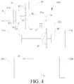
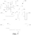
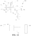
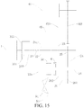
- a power transmission system 100 according to embodiments of the present invention will be described in detail below with reference to Figs. 1-19 .
- the power transmission system 100 is applicable to a vehicle, such as a hybrid vehicle with an engine unit 1 and a motor generator.
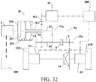
- the power transmission system 100 may include an engine unit 1, a transmission unit 2a, a first motor generator 41, a second motor generator 42, an output unit 5, and a power switching device (e.g., a synchronizer 6, and a clutch 9).
- a power switching device e.g., a synchronizer 6, and a clutch 9
- the transmission unit 2a is adapted to selectively be coupled with the engine unit 1.
- the engine unit 1 may selectively output a power generated by the engine unit 1 to the transmission unit 2a via the clutch 9 or the like.
- the transmission unit 2a may also output, for example, a starting torque from the first motor generator 41 to the engine unit 1, so as to start the engine unit 1.
- the phrase "the transmission unit 2a is coupled with the engine unit 1" means that the power can be transferred between the engine unit 1 and the transmission unit 2a directly or via other components, and the coupling between the transmission unit 2a and the engine unit 1 is also referred to as a power coupling.
- the engine unit 1 generates energy by mixing liquid or gaseous fuel and air and then combusting the mixed fuel and air therein, and the energy is converted into mechanical energy.
- the engine unit 1 of the vehicle may generally adopt a four-stroke gasoline or diesel engine.
- the engine unit 1 may generally include a block, a crank-connecting rod mechanism, a valve mechanism, a supply system, an ignition system, a cooling system, a lubrication system and the like.
- the block is an assembled body of individual mechanisms and systems of the engine unit 1.
- the crank-connecting rod mechanism may convert the linear reciprocating motion of a piston into the rotary motion of a crankshaft, and output a drive force.
- the valve mechanism is configured to charge or discharge a gas at a predetermined time, so as to ensure the smooth performing of each cycle of the engine unit 1.
- the supply system may supply a mixture of oil and gas to a cylinder for combustion.
- the cooling system is configured to cool the engine unit 1, so as to ensure that the operating temperature of the engine unit 1 is within a suitable temperature range.
- the lubrication system is configured to lubricate individual motion pairs in the engine unit 1, so as to reduce the wear and energy loss.
- the first motor generator 41 is coupled with the transmission unit 2a. In other words, the first motor generator 41 cooperates with the transmission unit 2a to transmit the power. That is, the first motor generator 41 may drive the transmission unit 2a, while the transmission unit 2a may drive the first motor generator 41.
- the engine unit 1 may output at least a part of the power generated thus to the first motor generator 41 via the transmission unit 2a, and the first motor generator 41 may generate electricity and convert mechanical energy into electric energy to be stored in an energy storage component such as a battery component.
- the first motor generator 41 may convert electric energy from the battery component into mechanical energy, and output the mechanical energy to the output unit 5 via the transmission unit 2a to drive the vehicle.
- the first motor generator 41 is a motor having functions of both a motor and a generator.
- the term "motor generator” refers to a motor having functions of both a motor and a generator, unless specified otherwise.
- the output unit 5 is configured to transmit a power transmitted by the transmission unit 2a to wheels 200 (e.g., one of front and rear wheels 210 and 220) of the vehicle. In short, the output unit 5 is adapted to output the power from the transmission unit 2a.
- the power switching device such as the synchronizer 6 is adapted to enable or interrupt a power transmitting between the output unit 5 and the transmission unit 2a.
- the power switching device may output the power output from the transmission unit 2a to at least one of front and rear wheels 210, 220 via the output unit 5, or the power switching device may also disconnect the transmission unit 2a from the output unit 5 and the transmission unit 2a may not output the power to the front and/or rear wheels 210, 220 via the output unit 5 directly.
- the second motor generator 42 is configured to drive the front and/or rear wheels 210, 220.
- the vehicle having the power transmission system 100 may be operable as a two-wheel drive vehicle.
- the vehicle having the power transmission system 100 may be operable as a four-wheel drive vehicle, and may switch between a two-wheel drive mode and a four-wheel drive mode.
- the output unit 5 is configured to drive the front wheels 210 and the rear wheels 220 and the second motor generator 42 is configured to drive the front wheels 210 or the rear wheels 220
- the vehicle having the power transmission system 100 may be operable as a four-wheel drive vehicle.
- the power output by at least one of the engine unit 1 and the first motor generator 41 may be output to the output unit 5 via the power switching device, and then output by the output unit 5 to the front and/or rear wheels 210, 220 of the vehicle.
- the second motor generator 42 may compensate for the torque of the front wheels 210 or the rear wheels 220, and may also cooperate with the engine unit 1 and the first motor generator 41 to drive the vehicle, thus increasing the number of operation modes of the vehicle. Therefore, the vehicle may be adapted to different operating conditions, thus achieving better fuel economic efficiency while reducing the emission of harmful gases.
- the power switching device is configured as a synchronizer 6, and the synchronizer 6 is adapted to selectively synchronize between the output unit 5 and the transmission unit 2a, so as to output the power via the output unit 5 to drive the wheels 200 of the vehicle.
- the function of the synchronizer 6 may be to eventually synchronize the output unit 5 and the transmission unit 2a, i.e., under the action of the synchronizer 6, the output unit 5 and the transmission unit 2a may operate synchronously, such that the power from the transmission unit 2a may be output with the output unit 5 as a power output terminal.
- the transmission unit 2a and the output unit 5 are not synchronized by the synchronizer 6, the power from the transmission unit 2a may not be output to the wheels 200 via the output unit 5 directly.
- the synchronizer 6 functions to switch the power. That is, when the synchronizer 6 is in an engaged state, the power from the transmission unit 2a may be output via the output unit 5 to drive the wheels 200; and when the synchronizer 6 is in a disengaged state, the transmission unit 2a may not transmit the power to the wheels 200 via the output unit 5. In this way, by controlling the synchronizer 6 to switch between the engaged state and the disengaged state, the switching of the drive mode of the vehicle may be realized.
- the synchronizer 6 Because of special application scenarios, compared to a clutch, the synchronizer 6 has the following advantages.
- the first motor generator 41 may adjust the speed of the transmission unit 2a, for example, the first motor generator 41 may adjust the speed of the transmission unit 2a with the rotating speed of the output unit 5 as a target value, so as to match the speed of the transmission unit 2a with the speed of the output unit 5 in a time efficient manner, thus reducing the time required by the synchronization of the synchronizer 6 and reducing the energy loss. Meanwhile, no torque engagement of the synchronizer 6 may be achieved, thus greatly improving the transmission efficiency, synchronization controllability and real-time synchronization of the vehicle. In addition, the life of the synchronizer 6 may be further extended, thus reducing the maintenance cost of the vehicle. Furthermore, the power transmission system 100 according to embodiments of the present invention is compact in structure and easy to control.
- the transmission unit 2a includes a transmission power input part 21 a and a transmission power output part 22a.
- the transmission power input part 21 a is selectively engaged with the engine unit 1 to transmit the power generated by the engine unit 1.
- the transmission power output part 22a is configured to output the power from the transmission power input part 21a to the output unit 5 via the synchronizer 6.
- the transmission power input part 21a further includes an input shaft (e.g., a first input shaft 21, a second input shaft 22) and a driving gear 25 mounted on the input shaft.
- the input shaft is selectively engaged with the engine unit 1 to transmit the power generated by the engine unit 1.
- the engine unit 1 may be engaged with the input shaft, such that the power output by the engine unit 1 may be transferred to the input shaft.
- the engagement between the engine unit 1 and the input shaft may be achieved by means of a clutch (e.g., a dual clutch 31), which will be described in detail below, and is no longer elaborated herein.
- the transmission power output part 22a includes an output shaft 24, and a driven gear 26 mounted on the output shaft 24 and configured to mesh with the driving gear 25 on the input shaft.
- the output shaft 24 is configured to output at least a part of the power transmitted by the input shaft.
- the output shaft 24 and the input shaft cooperate with each other to transmit the power.
- the power transmission between the output shaft 24 and the input shaft may be realized by means of the driving gear 25 and the driven gear 26.
- the power transmission between the output shaft 24 and the input shaft is not limited to this.
- the power transmission between the output shaft 24 and the input shaft may also be realized by means of a belt transmission mechanism, a rack and pinion transmission mechanism or the like.
- a suitable structure and manner of may be specifically selected according to practical applications by a person skilled in the art.
- the output shaft 24 is configured to transmit at least a part of the power on the input shaft.
- a part of the power on the input shaft may be used for the electricity generating of the first motor generator 41, and the other part of the power on the input shaft may be used to drive the vehicle to run.
- all power on the input shaft may be used for the electricity generation of the first motor generator 41.
- the power transmitting between the first motor generator 41 and one of the input shaft and the output shaft 24 may be direct or indirect.
- the term "direct power transmission” means that the first motor generator 41 is directly coupled with a corresponding one of the input shaft and the output shaft 24 for power transmission, without using any intermediate transmission components such as a speed changing device, a clutch device, or a transmission device.
- an output terminal of the first motor generator 41 can be directly and rigidly connected with one of the input shaft and the output shaft 24.
- the direct power transmission has the advantages of eliminating the intermediate transmission components and reducing the energy loss during the power transmission.
- the term "indirect power transmission” refers to any other power transmission manners other than the direct power transmission, for example, the power transmission by means of intermediate transmission components such as a speed changing device, a clutch device, or a transmission device.
- the indirect power transmission has the advantages of enabling convenient arrangement and achieving the desired transmission ratio by providing a speed changing device and the like.
- the output unit 5 may be used as a power output terminal of the output shaft 24 for outputting the power on the output shaft 24.
- the output unit 5 and the output shaft 24 may rotate differentially and not synchronously. In other words, there can be a rotating speed difference between the output unit 5 and the output shaft 24, and the output unit 5 and the output shaft 24 are not rigidly fixed with each other.
- the synchronizer 6 is disposed on the output shaft 24.
- the synchronizer 6 may include a splined hub 61 and a synchronizing sleeve 62.
- the splined hub 61 may be fixed on the output shaft 24 such that the splined hub 61 can rotate synchronously with the output shaft 24, while the synchronizing sleeve 62 may move in an axial direction of the output shaft 24 relative to the splined hub 61 so as to selectively engage with the output unit 5, such that the output unit 5 can rotate synchronously with the output shaft 24.
- the power may be transferred from the output unit 5 to the front and/or rear wheels 210, 220, thus driving the wheels 200.
- the structure of the synchronizer 6 is not limited to this.
- the power output by at least one of the engine unit 1 and the first motor generator 41 may be output from the output unit 5 by the engagement of the synchronizer 6, such that the power transmission system 100 is compact in structure and easy to control.
- the synchronizer 6 may switch from a disengaged state to an engaged state, and the first motor generator 41 may adjust the rotating speed of the output shaft 24 with the rotating speed of the output unit 5 as a target value, so as to match the rotating speed of the output shaft 24 with the rotating speed of the output unit 5 in a short time, thus facilitating the engagement of the synchronizer 6, greatly improving the transmission efficiency and reducing the energy loss, and realizing no torque engagement of the synchronizer 6.
- the radial frictional force is much smaller than the average value in the related art or even there is no radial frictional force during the engagement of the synchronizer 6.
- the output unit 5 is configured to drive a first pair of wheels of the vehicle, and there is a pair of second motor generators 42 configured to drive the first pair of wheels. Further, there may be a plurality of second motor generators.
- the power transmission system 100 further includes a third motor generator 43 configured to drive a second pair of wheels of the vehicle.
- the first pair of wheels refers to the front wheels 210 of the vehicle
- the second pair of wheels refers to the rear wheels 220 of the vehicle. It is understood that in other embodiments, the first pair of wheels can refer to the rear wheels 220 and the second pair of wheels can refer to the front wheels 210.
- the power transmission system 100 has four types of power output sources, i.e. the engine unit 1, the first motor generator 41, the second motor generator 42 and the third motor generator 43, in which the engine unit 1, the first motor generator 41 and the second motor generator 42 may be configured to drive one pair of wheels of the vehicle, and the third motor generator 43 may be configured to drive the other pair of wheels of the vehicle. Therefore, the vehicle having the power transmission system 100 is operable as a four-wheel drive vehicle.
- the synchronizer 6 may switch from the disengaged state to the engaged state, and the first motor generator 41 may adjust the rotating speed of the output shaft 24 with the rotating speed of the output unit 5 as a target value, so as to match the rotating speed of the output shaft 24 with the rotating speed of the output unit 5 in a short time, thus facilitating the engagement of the synchronizer 6, greatly improving the transmission efficiency and reducing the energy loss.
- the second motor generator 42 and the third motor generator 43 may compensate for the torque of the wheels 200, which is indirectly reflected in the output of the output unit 5. That is, the second motor generator 42 and the third motor generator 43 may indirectly adjust the rotating speed of the output unit 5.
- the second motor generator 42 and the third motor generator 43 may indirectly adjust the rotating speed of the output unit 5 according to requirements, so as to match the rotating speed of the output shaft 24 with the rotating speed of the output unit 5 in a short time, thus facilitating the engagement of the synchronizer 6.
- the second motor generator 42 and the third motor generator 43 may cooperate with the first motor generator 41 to adjust the rotating speed of the output unit 5 simultaneously, so as to synchronize the rotating speed of the output shaft 24 and the rotating speed of the output unit 5 in a shorter time, thus facilitating the engagement of the synchronizer 6 and greatly improving the transmission efficiency.
- the first motor generator 41 may adjust the rotating speed of the output unit 5 separately.
- at least one of the second motor generator 42 and the third motor generator 43 may adjust the rotating speed of the output unit 5 separately.
- the first motor generator 41, the second motor generator 42 and the third motor generator 43 may adjust the rotating speed of the output unit 5 simultaneously.
- the output of the power from the transmission unit 2a may be controlled by the engagement/disengagement of the synchronizer 6, and when the synchronizer 6 switches from the disengaged state to the engaged state, at least one of the first motor generator 41, the second motor generator 42 and the third motor generator 43 may compensate for the speeds of the output shaft 24 and the output unit 5, so as to match the rotating speed of the output shaft 24 with the rotating speed of the output unit 5 rapidly, thus realizing no torque engagement of the synchronizer 6 rapidly.
- the input shafts there is a plurality of the input shafts, i.e. two or more input shafts.
- the input shafts are coaxially nested sequentially. For example, if there are N input shafts, the K th input shaft is fitted over the (K-1) th input shaft, where N ⁇ K ⁇ 2, and central axes of the N input shafts coincide with each other.
- the engine unit 1 When the engine unit 1 transmits the power to the input shaft or is coupled with the input shaft for power transmitting, the engine unit 1 may be selectively engaged with one of the input shafts. In other words, when the power from the engine unit 1 needs to be output, the output terminal of the engine unit 1 may be engaged with one of the input shafts, so as to rotate synchronously with the one of the input shafts. When the engine unit 1 does not need to operate or the engine unit 1 is idle, the engine unit 1 may be disconnected from individual input shafts respectively, i.e. the engine unit 1 is not coupled with any input shaft, so as to interrupt the power transmission between the engine unit 1 and individual input shafts.
- one driving gear 25 is fixed on each input shaft, and the driving gear 25 rotates synchronously with the input shaft.
- the fixing between the driving gear 25 and the corresponding input shaft is not limited here, for example, the driving gear 25 and the corresponding input shaft may be fixed by, for example, key fit or hot pressing, or may be formed integrally, as long as the synchronous rotation of the driving gear 25 and the corresponding input shaft is ensured.
- a plurality of driven gears 26 is fixed on the output shaft 24, and the driven gears 26 rotate synchronously with the output shaft 24.
- the fixing between the driven gear 26 and the output shaft 24 may be realized by key fit or hot pressing, or may be formed integrally.
- the present invention is not limited to this.
- the number of the driving gears 25 on each input shaft is not limited to one, and accordingly a plurality of driven gears 26 is fixed on the output shaft 24 to form a plurality of gears, which is implementable to a person skilled in the art.
- the driven gears 26 are configured to mesh with the driving gears 25 on the input shafts respectively.
- the number of the driven gears 26 may be the same as that of the input shafts.
- the two driven gears 26 may be configured to mesh with the driving gears 25 on the two input shafts to transmit the power, so as to make the two pairs of gears form two gears for power transmitting.
- three or more input shafts may be provided according to the power transmitting requirements, and each input shaft may be provided with one driving gear 25. Therefore, the larger the number of the input shafts, the larger the number of the gears is, and the wider range of the transmission ratio of the power transmission system 100 is, so as to adapt to the power transmitting requirements of various vehicles.
- the input shafts include the first input shaft 21 and the second input shaft 22.
- the second input shaft 22 is fitted over the first input shaft 21.
- the second input shaft 22 is a hollow shaft, and the first input shaft 21 is preferably a solid shaft.
- the first input shaft 21 may also be a hollow shaft.
- the first input shaft 21 may be supported by bearings.
- a plurality of bearings can be preferably disposed in an axial direction of the first input shaft 21 at a position not influencing the assembly of other components.
- the second input shaft 22 may also be supported by bearings.
- a dual clutch 31 is disposed between the engine unit 1 and the first and second input shafts 21, 22.
- the dual clutch 31 may be a dry dual clutch 31 or a wet dual clutch 31.
- the dual clutch 31 has an input terminal 313, a first output terminal 311 and a second output terminal 312.
- the engine unit 1 is connected to the input terminal 313 of the dual clutch 31.
- the engine unit 1 may be connected to the input terminal 313 of the dual clutch 31 via for example, a flywheel, a damper, or a torsion plate.
- the first output terminal 311 of the dual clutch 31 is connected to and rotates synchronously with the first input shaft 21.
- the second output terminal 312 of the dual clutch 31 is connected to and rotates synchronously with the second input shaft 22.
- the input terminal 313 of the dual clutch 31 may be a shell of the dual clutch 31, and the first output terminal 311 and the second output terminal 312 of the dual clutch 31 may be two driven discs.
- the shell may be disconnected from the two driven discs, such that the input terminal 313 is disconnected from the first output terminal 311 and the second output terminal 312.
- the shell can be controlled to engage with the corresponding driven disc to rotate synchronously with the driven disc, e.g. the input terminal 313 is engaged with one of the first output terminal 311 and the second output terminal 312, such that the power transmitted from the input terminal 313 may be output via one of the first output terminal 311 and the second output terminal 312.
- the shell is engaged with one driven disc at a time.
- control strategy may be adaptively set according to the desired power transmission mode, e.g. switching between a mode in which the input terminal 313 is disconnected from the first output terminal 311 and the second output terminal 312 and a mode in which the input terminal 313 is engaged with one of the first output terminal 311 and the second output terminal 312.
- the transmission unit 2a since the input shaft has a concentric dual-shaft structure and each input shaft is provided with only one driving gear 25, the transmission unit 2a has two different gears, and the engine unit 1 may output the power to the output unit 5 via the two gears, while the synchronizer 6 is always in an engaged state to engage the output shaft 24 with the output unit 5.
- the synchronizer 6 does not need to be first disengaged and then move axially to engage with other gears. Only the engagement/disengagement of the dual clutch 31 needs to be controlled, while the synchronizer 6 can remain in the engaged state. In this way, when the engine unit 1 outputs the power to the output unit 5, only one gear shift actuating component, e.g. the dual clutch 31, needs to be controlled, while the synchronizer 6 does not need to be controlled, thus simplifying the control strategy greatly, reducing the number of engagement/disengagement times of, e.g. synchronizer 6, and extending the life of the synchronizer 6.
- the first motor generator 41 is configured to cooperate with one of the driving gear 25 and the driven gear 26 for power transmission. In other words, indirect power transmission between the first motor generator 41 and one of the input shaft and the output shaft 24 is performed.
- an intermediate transmission mechanism may be disposed between the first motor generator 41 and the corresponding gear, and by way of example and without limitation, the intermediate transmission mechanism may be a worm and worm gear transmission mechanism, a one-stage or multi-stage gear pair transmission mechanism, or a chain wheel transmission mechanism, or may be a combination of the above transmission mechanisms in the case of no conflicting.
- the first motor generator 41 may be provided in different locations as needed, thus reducing the arrangement difficulty of the first motor generator 41.
- the first motor generator 41 may transmit the power via an intermediate gear 411.
- an intermediate gear 411 For example, as shown in Fig. 3 (with reference to Fig. 2 ), indirect power transmission between the first motor generator 41 and the driving gear 25 on the first input shaft 21 via the intermediate gear 411 can be performed. As another example, as shown in Fig. 2 , indirect power transmission between the first motor generator 41 and the driving gear 25 on the second input shaft 22 via the intermediate gear 411 can be performed
- the first motor generator 41 may be configured to connect with one of the first input shaft 21 and the output shaft 24.
- the first motor generator 41 may be configured to directly connect with the first input shaft 21.
- the first motor generator 41 may be configured to directly connect with the output shaft 24. Direct connection between the first motor generator 41 and the corresponding shaft may make the structure of the power transmission system 100 more compact, and decrease the circumferential dimension of the power transmission system 100, such that the power transmission system 100 may be easily disposed in a compartment of the vehicle.
- the first motor generator 41 is arranged coaxially with the first input shaft 21, and the first motor generator 41 is arranged coaxially with the engine unit 1.
- the first motor generator 41 is arranged coaxially with the engine unit 1" would be appreciated as that a rotation axis of a rotor of the first motor generator 41 substantially coincides with a rotation axis of a crankshaft of the engine unit 1. Therefore, the power transmission system 100 becomes more compact in structure.
- the output unit 5 may include an output gear 51 and an engagement gear ring 52.
- the output gear 51 may rotate relative to the output shaft 24, i.e. rotate differentially relative to the output shaft 24, and the engagement gear ring 52 is fixedly connected with the output gear 51, i.e. the engagement gear ring 52 rotates synchronously with the output gear 51.
- the synchronizing sleeve 62 of the synchronizer 6 may axially move toward the engagement gear ring 52, and after the rotating speed of the output unit 5 is synchronized with the rotating speed of the output shaft 24, the synchronizing sleeve 62 may be engaged with the engagement gear ring 52 to form a rigid connection between the output shaft 24, the synchronizer 6 and the output unit 5, so as to rotate the output shaft 24, the synchronizer 6 and the output unit 5 synchronously.
- the output gear 51 may be a driving gear of a final drive and is configured to directly mesh with a driven gear 53 of the final drive to output the power, so as to drive the wheels 200.
- the present invention is not limited to this, and other intermediate transmission components may also be disposed between the output gear 51 and the final drive.
- a differential 54 is disposed between the first pair of wheels such as the front wheels 210.
- the differential 54 cooperates with the output unit 5 for power transmitting.
- the differential 54 is provided with the driven gear 53 thereon, and the output gear 51 becomes the driving gear of the final drive configured to mesh with the driven gear 53 of the final drive, such that the power may be transferred to the two front wheels 210 via the driving gear of the final drive, the driven gear 53 of the final drive and the differential 54 sequentially.
- the function of the differential 54 is to properly distribute the power to the two front wheels 210.
- the differential 54 may be a gear differential, a mandatory locking differential, or the Torsen differential, which may be selected by a person skilled in the art according to different vehicles.
- a pair of second motor generators 42 is disposed on two sides of the differential 54 back to back.
- a pair of second motor generators 42 is disposed on two sides of the differential 54 and integrally formed with the differential 54.
- the left second motor generator 42 can be disposed between a left half shaft and the left side of the differential 54
- the right second motor generator 42 can be disposed between a right half shaft and the right side of the differential 54.
- the power transmission system 100 in Figs. 5-7 is operable in a four-wheel drive mode
- the power transmission system 100 in Fig. 10 is operable in a two-wheel drive mode. It should be noted that in the following, when referring to "motor generators are disposed on two sides of the differential 54 back to back,” it means that the motor generators are disposed on two sides of the differential 54 respectively and integrally formed with the differential 54.
- the second motor generator 42 is a wheel-side motor.
- one of the second motor generators 42 is disposed at an inner side of the left front wheel
- the other of the second motor generators 42 is disposed at an inner side of the right front wheel
- the second motor generator 42 may transfer the power to a hub of a corresponding wheel via a gear mechanism.
- the power transmission system 100 in Figs. 2-4 is operable in a four-wheel drive mode
- the power transmission system 100 in Fig. 9 is operable in a two-wheel drive mode.
- two third motor generators 43 are provided, and the third motor generators 43 are a wheel-side motor, as shown in Figs. 2 and 5 .
- the third motor generators 43 are a wheel-side motor, as shown in Figs. 2 and 5 .
- one of the third motor generators 43 is disposed at an inner side of the left rear wheel
- the other of the third motor generators 43 is disposed at an inner side of the right rear wheel
- the third motor generator 43 may transfer the power to a corresponding rear wheel via a gear mechanism.
- one third motor generator 43 is provided, and the third motor generator 43 drives the second pair of wheels via a first speed changing mechanism 71.
- the first speed changing mechanism 71 is preferably a reducing mechanism, and the reducing mechanism may be a one-stage or multi-stage reducing mechanism.
- the reducing mechanism may include, but is not limited to, a gear reducing mechanism, or a worm and worm gear reducing mechanism.
- the second pair of wheels may be connected with each other via an axle which may have an integral structure.
- the third motor generator 43 may directly drive the integral axle via the first speed changing mechanism 71, to drive the two wheels to rotate synchronously.
- each third motor generator 43 drives one of the second pair of wheels via a second speed changing mechanism 72.
- the second speed changing mechanism 72 is preferably a reducing mechanism, and the reducing mechanism may be a one-stage or multi-stage reducing mechanism.
- the reducing mechanism may include, but is not limited to, a gear reducing mechanism, or a worm and worm gear reducing mechanism.
- the two wheels in the second pair may be connected with the corresponding third motor generators 43 and the corresponding second speed changing mechanisms 72 via two half axles respectively.
- one of the third motor generators 43 may drive a corresponding half axle via one of the second speed changing mechanisms 72, so as to drive the wheel at an outer side of the half axle to rotate.
- the power transmission system 100 is operable in a two-wheel drive mode.
- the output unit 5 drives the front wheels 210
- the second motor generator 42 is a wheel-side motor and is configured to drive the front wheels 210.
- the output unit 5 drives the front wheels 210
- the second motor generators 42 are disposed at two sides of the differential 54 back to back, for example, the second motor generators 42 are disposed at two sides of the differential 54 respectively and integrally formed with the differential 54.
- the power transmission system 100 is operable in a four-wheel drive mode. In an example shown in Fig.
- the output unit 5 drives the front wheels 210, two second motor generators 42 are provided, and each second motor generator 42 drives one rear wheel 220 via one fourth speed changing mechanism 74.
- the output unit 5 drives the front wheels 210, one second motor generator 42 is provided, and the second motor generator 42 drives the rear wheels 220 via one third speed changing mechanism 73.
- the output unit 5 drives the front wheels 210, two second motor generators 42 are provided and are wheel-side motors, which are configured to drive the rear wheels 220.
- the third speed changing mechanism 73 may be the same as the first speed changing mechanism 71.
- the fourth speed changing mechanism 74 may be the same as the second speed changing mechanism 72. Therefore, the third speed changing mechanism 73 and the fourth speed changing mechanism 74 will not be described in detail here.
- the power transmission system 100 may also include a battery component 300.
- the battery component 300 is preferably connected with the first motor generator 41, the second motor generator 42 and the third motor generator 43 respectively. Therefore, the first motor generator 41 is driven by the engine unit 1 to generate electricity or electric energy recovered by the first motor generator 41 during the braking may be supplied to and stored in the battery component 300, and electric energy recovered by the second motor generator 42 and the third motor generator 43 during the braking may also be supplied to and stored in the battery component 300.
- the battery component 300 may supply electric energy to at least one of the first motor generator 41, the second motor generator 42 and the third motor generator 43. It would be appreciated that the dot lines shown in Fig. 8 indicate that the battery component 300 may be electrically connected with the first motor generator 41, the second motor generator 42 and the third motor generator 43 respectively.
- the power transmission system 100 includes input shafts, which include three shafts, e.g. the first input shaft 21, the second input shaft 22 and the third input shaft 23, with the second input shaft 22 being fitted over the first input shaft 21, and the third input shaft 23 being fitted over the second input shaft 22.
- the power transmission system 100 further includes a triple clutch 32.
- the triple clutch 32 has an input terminal 324, a first output terminal 321, a second output terminal 322 and a third output terminal 323.
- the engine unit 1 is coupled with the input terminal 324 of the triple clutch 32, the first output terminal 321 of the triple clutch 32 is coupled with the first input shaft 21, the second output terminal 322 of the triple clutch 32 is coupled with the second input shaft 22, and the third output terminal 323 of the triple clutch 32 is coupled with the third input shaft 23.
- the input terminal 324 of the triple clutch 32 may be a shell thereof, and the first, second and third output terminals 321, 322, 323 of the triple clutch 32 may be three driven discs.
- the input terminal 324 may be engaged with one of the first, second and third output terminals 321, 322, and 323, or may be disconnected with the first, second and third output terminals 321, 322, and 323. It would be appreciated that the operation principle of the triple clutch 32 is similar to that of the dual clutch 31, so the detailed description thereof will be omitted here.
- the power transmission system 100 includes a driven gear 26 which is configured as a linked gear, and the linked gear structure 26 is freely fitted over the output shaft 24 and rotates differentially relative to the output shaft 24.
- the synchronizer 6 is disposed on the output shaft 24 and may be selectively engaged with the linked gear structure 26.
- the linked gear structure 26 can be a double-linked gear.
- the double-linked gear structure 26 has a first gear part 261 and a second gear part 262, and the first gear part 261 and the second gear part 262 are configured to mesh with two driving gears 25 respectively.
- the synchronizer 6 may be engaged with the double-linked gear structure 26, such that the power output by at least one of the engine unit 1 and the first motor generator 41 may be output via the output unit 5 and, e.g., the driving gear 51 of the final drive.
- the power transmitting between the first motor generator 41 and the output shaft or one of the output shafts may be direct or indirect, and is similar to that described in the above embodiments, so the detailed description thereof will be omitted here.
- the arrangement of other components such as the clutch (e.g., the dual clutch 31 or the triple clutch 32) between the engine unit 1 and the input shaft is similar to that described in the above embodiments, so the detailed description thereof will also be omitted here.
- the power transmission system 100 may include an engine unit 1, a plurality of input shafts, an output shaft 24, an output unit 5 (e.g., the driving gear 51 of the final drive), a synchronizer 6 and a first motor generator 41.
- a main difference of these alternative embodiments from the power transmission system 100 shown in Figs. 2-13 is that a driven gear 26 which is a linked gear and can be freely fitted over the output shaft 24. With the output unit 5 fixed on the output shaft 24, the synchronizer 6 can be configured to engage with the linked gear.
- the arrangement of the first motor generator 41 may slightly differ from that of the first motor generator 41 in the power transmission system 100 shown in Figs. 2-13 .
- a plurality of input shafts is provided, the input shafts are provided with the driving gears 25 thereon.
- the linked gear structure 26 is freely fitted over the output shaft 24.
- the linked gear structure 26 has a plurality of gear parts (for example, the first gear part 261, and the second gear part 262), and the gear parts are configured to mesh with the driving gears 25 on the input shafts respectively.
- the output unit 5 is configured to output the power from the output shaft 24.
- the output unit 5 is fixed on the output shaft 24.
- the output unit 5 may include the driving gear 51 of the final drive.
- the synchronizer 6 is disposed on the output shaft 24.
- the synchronizer 6 is configured to selectively engage with the linked gear structure 26, so as to output the power via the output unit 5 to drive the wheels of the vehicle.
- the power transmission between the first motor generator 41 and one of the input shaft and the output shaft 24 may be direct or indirect.
- the function of the synchronizer 6 is substantially the same as that of the synchronizer 6 shown in Figs. 2-13 .
- the synchronizer 6 in these embodiments are configured to engage the linked gear structure 26 with the output shaft 24, while the synchronizer 6 shown in the embodiments in Figs. 2-13 is configured to engage the output unit 5 with the output shaft 24.
- the function of the synchronizer 6 is to eventually synchronize the linked gear structure 26 with the output shaft 24, so that the linked gear structure 26 and the output shaft 24 can operate synchronously to output the power from at least one of the engine unit 1 and the first motor generator 41 with the output unit 5 as a power output terminal.
- the linked gear structure 26 and the output shaft 24 are not synchronized by the synchronizer 6, the power from at least one of the engine unit 1 and the first motor generator 41 may not be directly output to the wheels 200 via the output unit 5.
- the synchronizer 6 functions to switch the power. That is, when the synchronizer 6 is in an engaged state, the power from at least one of the engine unit 1 and the first motor generator 41 may be output via the output unit 5 to drive the wheels 200; and when the synchronizer 6 is in a disengaged state, the power from at least one of the engine unit 1 and the first motor generator 41 may not be transmitted to the wheels 200 via the output unit 5. In this way, by controlling the synchronizer 6 to switch between the engaged state and the disengaged state, the switching of the drive mode of the vehicle may be realized.
- the first motor generator 41 may adjust the speed of the linked gear structure 26 with the rotating speed of the output shaft 24 as a target value, so as to match the speed of the linked gear structure 26 with the speed of the output shaft 24 in a time efficient manner, thus reducing the time required by the synchronization of the synchronizer 6 and reducing the energy loss. Meanwhile, no torque engagement of the synchronizer 6 may be achieved, thus greatly improving the transmission efficiency, synchronization controllability and real-time synchronization of the vehicle. In addition, the life of the synchronizer 6 may be further extended, thus reducing the maintenance cost of the vehicle.
- the power transmission system 100 is more compact in structure and easy to arrange, and the number of the driven gears may be decreased so as to reduce the axial dimension of the power transmission system 100, thus reducing the cost and the arrangement difficulty.
- the synchronizer 6 may be controlled by one separate fork, such that the control steps are simple and the reliability is high.
- the input shafts are coaxially nested, and each input shaft is provided with one driving gear 25.
- the input shafts include a first input shaft 21 and a second input shaft 22, and each input shaft is provided with one driving gear 25.
- the linked gear structure 26 is a double-linked gear, the double-linked gear structure 26 has a first gear part 261 and a second gear part 262, and the first gear part 261 and the second gear part 262 are configured to mesh with two driving gears 25 respectively.
- a dual clutch 31 may be disposed between the engine unit 1 and the first and second input shafts 21 and 22.
- the dual clutch 31 may be provided with a damping structure thereon.
- the damping structure may be arranged between a first output terminal and an input terminal of the dual clutch 31, to adapt to start the vehicle at a low gear.
- the power transmission system 100 in these embodiments further includes an intermediate shaft 45.
- a first intermediate shaft gear 451 and a second intermediate shaft gear 452 are fixed on the intermediate shaft 45.
- One of the first and second intermediate shaft gears 451 and 452 is configured to mesh with one driving gear 25.
- the first intermediate shaft gear 451 is configured to mesh with the driving gear 25 on the second input shaft 22.
- the present invention is not limited to these examples.
- direct power transmission between the output terminal of the first motor generator 41 and one of the first and second intermediate shaft gears 451 and 452, or indirect power transmission between the output terminal of the first motor generator 41 and one of the first and second intermediate shaft gears 451 and 452 via an intermediate idler 44 can be performed.
- indirect power transmitting between the output terminal of the first motor generator 41 and the second intermediate shaft gear 452 via an intermediate idler 44 is performed.
- the output terminal of the first motor generator 41 is configured to directly mesh with the second intermediate shaft gear 452 for power transmission.
- the output terminal of the first motor generator 41 is configured to directly mesh with one gear part of the linked gear structure 26.
- the output terminal of the first motor generator 41 can be configured to directly mesh with the first gear part 261 for power transmission.
- the position of the first motor generator 41 may be designed according to practical requirements.
- the position of the first motor generator 41 may be the same as that described above, or may be as shown in Figs. 2-13 , which will not be described in detail here.
- the first gear part 261 inputs a torque to the engine unit 1 separately, and the second gear part 262 may input a torque to the engine unit 1 and the first motor generator 41 simultaneously.
- an engagement gear ring 52 is fixed on a side of the linked gear structure 26 facing the synchronizer 6, and the synchronizer 6 is adapted to engage with the engagement gear ring 52, such that the linked gear structure 26 is rigidly fixed with the output shaft 24 to rotate synchronously with the output shaft 24.
- the synchronizer 6 in the above embodiments can be replaced with a clutch 9.
- the power switching device is a clutch 9.
- the clutch 9 is adapted to enable or interrupt a power transmission between the transmission unit 2a and the output unit 5.
- the transmission unit 2a and the output unit 5 may operate synchronously, and the output unit 5 may output the power from the transmission unit 2a to the wheels 200.
- the clutch 9 is in a disengaged state, the power output by the transmission unit 2a may not be directly output via the output unit 5.
- the double-linked gear structure 26 is freely fitted over the output shaft 24, and the output unit 5 is fixed on the output shaft 24.
- the clutch 9 has a driving part (C driving in Fig. 17 ) and a driven part (C driven in Fig. 17 ).
- One of the driving part and the driven part of the clutch 9 is disposed on a linked gear structure such as a double-linked gear 26, and the other of the driving part and the driven part of the clutch 9 is disposed on the output shaft 24.
- the driving part and the driven part of the clutch 9 may be disengaged from or engaged with each other.
- the driving part may be disposed on the output shaft 24, and the driven part may be disposed on the linked gear structure 26, but the present invention is not limited to this.
- the output shaft 24 is engaged with the double-linked gear structure 26 freely fitted over the output shaft 24, so as to output the power via the output unit 5.
- the linked gear structure 26 is freely fitted over the output shaft 24, and the output unit 5 does not transfer the power from the transmission unit 2a.
- the power transmission system 100 since the synchronizer 6 is used for power switching and has advantages of small volume, simple structure, large torque transmission and high transmission efficiency, the power transmission system 100 according to embodiments of the present invention has a reduced volume, a more compact structure and high transmission efficiency, and may meet the large-torque transmission requirements.
- a mechanical four-wheel drive vehicle may only achieve the torque distribution of front and rear wheels, and a full-time four-wheel drive vehicle may only achieve small difference in instantaneous torque of left and right wheels.
- the engine unit 1 is coupled with the input terminal 313 of the dual clutch 31, the first output terminal 311 of the dual clutch 31 is coupled with the first input shaft 21, the second output terminal 312 of the dual clutch 31 is coupled with the second input shaft 22, and the second input shaft 22 is coaxially fitted over the first input shaft 21.
- Each of the first input shaft 21 and the second input shaft 22 is fixedly provided with one driving gear 25, and indirect power transmission between the first motor generator 41 and the driving gear 25 on the second input shaft 22 is performed via one intermediate gear 411.
- the output shaft 24 is fixedly provided with two driven gears 26, and the two driven gears 26 are configured to mesh with the driving gears 25 on the first input shaft 21 and the second input shaft 22, to form two gears.
- the synchronizer 6 is disposed on the output shaft 24, the driving gear (e.g. the output gear 51) of the final drive may rotate differentially relative to the output shaft 24, while the engagement gear ring 52 adapted to the synchronizer 6 is fixed on a left side of the driving gear of the final drive by using a connecting rod.
- the driving gear of the final drive is configured to externally mesh with the driven gear 53 of the final drive, and the driven gear 53 of the final drive may be fixed on the differential 54, to transfer the power to the differential 54.
- the differential 54 distributes the power and adaptively transfers the distributed power to half axles on two sides of the vehicle, to drive the wheels 200.
- Two second motor generators 42 constitute wheel-side motors configured to drive two front wheels 210 respectively
- two third motor generators 43 constitute wheel-side motors configured to drive two rear wheels 220 respectively. That is, in the solution, each of the four wheels is provided with one wheel-side motor.
- the power from the engine unit 1 may be transferred to the output shaft 24 with two different transmission ratios respectively.
- the first motor generator 41 may transfer the power to the output shaft 24 with a constant transmission ratio via a shift gear set.
- the power from the output shaft 24 may be transferred to the front wheels 210 via the final drive and the differential 54.
- the power from the output shaft 24 may not be transferred to the front wheels 210.
- the two second motor generators 42 are wheel-side motors, and may directly drive two front wheels 210 respectively.
- the two third motor generators 43 are wheel-side motors, and may directly drive two rear wheels 220 respectively.
- the power transmission system 100 in this embodiment may have at least the following operating conditions: a pure electric vehicle (EV) operating condition of the third motor generator 43, a pure EV four-wheel drive operating condition, a parallel operating condition, a series operating condition, and a braking/decelerating feedback operating condition.
- a pure electric vehicle (EV) operating condition of the third motor generator 43 a pure electric vehicle four-wheel drive operating condition, a parallel operating condition, a series operating condition, and a braking/decelerating feedback operating condition.
- This operating condition is a pure EV operating condition of the third motor generator 43.
- the dual clutch 31 is in a disengaged state
- the synchronizer 6 is in a disengaged state
- the engine unit 1 the first motor generator 41 and the second motor generator 42 do not operate
- two third motor generators 43 drive two rear wheels 220 respectively.
- This operating condition is mainly applicable to a situation where a load is small and an electric quantity of a battery is large, for example, during uniform motions or under urban operating conditions.
- This operating condition has the advantages that since the third motor generators 43 directly drive the rear wheels 220, compared to a front-wheel drive vehicle, the vehicle in this embodiment has better acceleration performance, gradeability and steering capability. Moreover, since the third motor generators 43 independently drive the left rear wheel and the right rear wheel respectively, an electronic differential function may be achieved, thus increasing the operating stability and reducing the amount of tire wear. In a front-wheel drive part, since the association between the output gear 51 and the front wheels 210 is interrupted by the synchronizer 6, there is no mechanical loss in the front-wheel drive part, thus reducing the energy consumption of the vehicle.
- This operating condition is a pure EV four-wheel drive operating condition.
- the dual clutch 31 is in a disengaged state
- the synchronizer 6 is in a disengaged state
- the first motor generator 41 does not operate
- two second motor generators 42 are configured to drive two front wheels 210 respectively
- two third motor generators 43 are configured to drive two rear wheels 220 respectively.
- This operating condition is mainly applicable to a situation where a load is large and an electric quantity of a battery is large, for example, during acceleration, climbing, overtaking, or high-speed running.
- This operating condition has the advantages of having better dynamic performance than a single-motor drive, and having better economic efficiency and lower noise than a hybrid drive.
- a typical application highlighting the advantages of this operating condition is traffic congestion at a steep slope (mountain road).
- a pure EV four-wheel drive vehicle has better acceleration performance, gradeability, handling performance and off-road capability. Since two second motor generators 42 and two third motor generators 43 drive four wheels independently, the wheels may obtain different torques and rotating speeds, to achieve the individual control on the four wheels, thus maximizing the dynamic performance, operating stability and off-road performance. Furthermore, when torques in different directions are applied to the left and right wheels by corresponding motor generators, the in-situ steering of the vehicle may be realized.
- This operating condition is a parallel operating condition.
- the dual clutch 31 is in an engaged state
- the synchronizer 6 is in an engaged state
- the engine unit 1 and the first motor generator 41 transfer the power to the driving gear 51 of the final drive via the shift gear set and the synchronizer 6, and the driving gear 51 of the final drive transfers the power to the front wheels 210 via the differential 54
- two second motor generators 42 transfer the power to the corresponding front wheels 210
- two third motor generators 43 transfer the power to the corresponding rear wheels 220.
- This operating condition is mainly applicable to a situation where a load is the largest, for example, during quick acceleration, or climbing steep slopes.
- This operating condition has the advantages that the five motor generators and the engine unit 1 drive the vehicle simultaneously, thus maximizing the dynamic performance.
- a HEV four-wheel drive vehicle has better acceleration performance, gradeability, handling performance and off-road capability.
- the third motor generators 43 independently drive the left rear wheel and the right rear wheel respectively, an electronic differential function may be achieved, and a mechanical differential in the related art is avoided, thus reducing parts while increasing the handling stability and reducing the amount of tire wear.
- This operating condition is a series operating condition.
- the dual clutch 31 is in an engaged state
- the synchronizer 6 is in a disengaged state
- the engine unit 1 drives the first motor generator 41 via the dual clutch 31 and the shift gear set to generate electricity
- the second motor generators 42 are configured to drive the front wheels 210 respectively
- the third motor generators 43 are configured to drive the rear wheels 220 respectively.
- This operating condition is mainly applicable to a situation where a load is medium and an electric quantity of a battery is small.
- This operating condition has the advantages that, when compared to a front-wheel drive vehicle and a rear-wheel drive vehicle, the vehicle under the series (e.g. four-wheel drive series) operating condition has better acceleration performance, gradeability, handling performance and off-road capability. Since two second motor generators 42 and two third motor generators 43 drive four wheels independently, the wheels may obtain different torques and rotating speeds, so as to achieve the individual control on the four wheels, thus maximizing the dynamic performance, handling stability and off-road performance. Furthermore, when torques in different directions are applied to the left and right wheels by corresponding motor generators, the in-situ steering of the vehicle may be realized. Moreover, the first motor generator 41 may keep the engine unit 1 running in an optimal economic region through torque and rotating speed adjustment, thus reducing fuel consumption during the electricity generation.
- the series e.g. four-wheel drive series
- This operating condition is a braking/decelerating feedback operating condition.
- the dual clutch 31 is in an engaged state, the synchronizer 6 is in a disengaged state, the engine unit 1 drives the first motor generator 41 to generate electricity, the second motor generators 42 brake the front wheels 210 and generate electricity, and the third motor generators 43 brake the rear wheels 220 and generate electricity.
- This operating condition is mainly used for braking or decelerating the vehicle.
- This operating condition has the advantages that, since the second motor generator 42 and the third motor generator 43 brake four wheels respectively during the decelerating or braking, whether the vehicle is turning or moving straightly, the power of each wheel may be fully absorbed, in the premise of ensuring the braking force and stability of the vehicle, thus maximizing the energy feedback. Moreover, because of the disengagement of the synchronizer 6, while the four motor generators brake the four wheels respectively, the engine unit 1 and the first motor generator 41 may continue generating electricity, so as to enable a stable electricity generation state, avoid frequent switching, and extend the life of components.
- This operating condition is a series-parallel operating condition.
- the dual clutch 31 is in an engaged state
- the synchronizer 6 is in an engaged state
- a part of the power from the engine unit 1 drives the first motor generator 41 via the dual clutch 31 and the shift gear set to generate electricity
- the other part of the power from the engine unit 1 is transferred to the driving gear 51 of the final drive via the shift gear set and the synchronizer 6,
- the second motor generators 42 drive the front wheels 210 directly via the driving gear 51 of the final drive
- the third motor generators 43 drive the rear wheels 220 respectively.
- This operating condition is mainly applicable to a situation where a load is large and an electric quantity of a battery is small, for example, during acceleration or climbing.
- This operating condition has the advantages of exploiting all the power from the engine unit 1, ensuring the dynamic performance of the vehicle while generating electricity, and maintaining the electric quantity of the battery.
- the above six operating conditions may be switched, and typical switching between operating conditions is switching from the fourth operating condition to the third operating condition, or switching from the fourth operating condition to the fifth operating condition.
- the power transmission system 100 may switch from the fourth operating condition to the third operating condition.
- the first motor generator 41 may adjust the rotating speed of the output shaft 24 with the rotating speed of the driving gear of the final drive as a target value through the rotating speed control, so as to match the rotating speed of the output shaft 24 with the rotating speed of the driving gear of the final drive as far as possible, thus facilitating the engagement of the synchronizer 6.
- the second motor generators 42 and the third motor generators 43 may respond to the needs of the driver to increase the torque, such that the vehicle is accelerated, unlike a vehicle in the related art, the vehicle needs not to be accelerated only when the synchronizer 6 is in an engaged state.
- the torque compensation in advance may greatly shorten the torque response time and improve the instantaneous acceleration performance of the vehicle.
- the switching from the fourth operating condition to the fifth operating condition will be described as follows.
- the power transmission system 100 may switch from the fourth operating condition to the fifth operating condition.
- the second motor generators 42 and the third motor generators 43 may meet the braking feedback requirements, and the feedback of the first motor generator 41 is not needed.
- the second motor generators 42 and the third motor generators 43 may instantly respond to the needs of the driver to brake the wheels and feed back the electric quantity, which need not be like a vehicle in the related art which feeds back the electric quantity only when the synchronizer 6 is in an engaged state.
- the engine unit 1 and the first motor generator 41 may be kept generating electricity, under the braking operating condition and the series operating condition.
- the torque compensation in advance may greatly shorten the motor braking response time and increase the feedback electric quantity.
- the engagement of the synchronizer 6 can be difficult due to the changing speed of the vehicle.
- the first motor generator 41 may adjust the rotating speed of the output shaft 24 through the rotating speed control, since the rotating speed of the driving gear of the final drive along with the speed of the vehicle may not be controllable, the speed adjusting accuracy and rate of the first motor generator 41 may be reduced.
- the second motor generators 42 and the third motor generators 43 may compensate for the torque of the vehicle, the speed of the vehicle may be stabilized effectively, thus improving the driving experience of the vehicle and simplifying the engagement of the synchronizer 6.
- the power transmission system 100 in this embodiment differs from the power transmission system 100 shown in Fig. 2 in the arrangement of the third motor generators 43.
- each third motor generator 43 drives a corresponding rear wheel 220 via one second speed changing mechanism 72.
- Other parts in this embodiment are substantially the same as those in the power transmission system 100 in the embodiment shown in Fig. 2 , so the detailed description thereof will be omitted here.
- the specific operating conditions of the power transmission system 100 in this embodiment are substantially the same as those of the power transmission system 100 in the embodiment shown in Fig. 2 , except that the power transfer between the third motor generators 43 and the corresponding rear wheels 220 is performed via the second speed changing mechanism 72, which will not be detailed here.
- the power transmission system 100 in this embodiment differs from the power transmission system 100 shown in Fig. 2 in the arrangement of the third motor generators 43.
- one third motor generator 43 is provided and drives the rear wheels 220 via one first speed changing mechanism 71.
- Other parts in this embodiment are substantially the same as those in the power transmission system 100 in the embodiment shown in Fig. 2 , so the detailed description thereof will be omitted here.
- the specific operating conditions of the power transmission system 100 in this embodiment are substantially the same as those of the power transmission system 100 in the embodiment shown in Fig.
- the differential function of the rear wheels 220 may not be realized by means of only one motor and one speed changing mechanism, however, it would be appreciated that a differential integrally formed with the first speed changing mechanism 71 may be added to realize the differential rotation of the two rear wheels 220.
- the power transmission system 100 in this embodiment differs from the power transmission system 100 shown in Fig. 2 in the arrangement of the second motor generators 42.
- the second motor generators 42 are disposed at two sides of the differential 54 back to back respectively.
- Other parts in this embodiment are substantially the same as those in the power transmission system 100 in the embodiment shown in Fig. 2 , so the detailed description thereof will be omitted here.
- the specific operating conditions of the power transmission system 100 in this embodiment are substantially the same as those of the power transmission system 100 in the embodiment shown in Fig. 2 , which will not be detailed here.
- the power transmission system 100 in this embodiment differs from the power transmission system 100 shown in Fig. 5 in the arrangement of the third motor generators 43.
- each third motor generator 43 drives a corresponding rear wheel 220 via one second speed changing mechanism 72.
- Other parts in this embodiment are substantially the same as those in the power transmission system 100 in the embodiment shown in Fig. 2 , so the detailed description thereof will be omitted here.
- the specific operating conditions of the power transmission system 100 in this embodiment are substantially the same as those of the power transmission system 100 in the embodiment shown in Fig. 2 , which will not be detailed here.
- the power transmission system 100 in this embodiment differs from the power transmission system 100 shown in Fig. 5 in the arrangement of the third motor generators 43.
- one third motor generator 43 is provided and drives the rear wheels 220 via one first speed changing mechanism 71.
- Other parts in this embodiment are substantially the same as those in the power transmission system 100 in the embodiment shown in Fig. 5 , so the detailed description thereof will be omitted here.
- the specific operating conditions of the power transmission system 100 in this embodiment are substantially the same as those of the power transmission system 100 in the embodiment shown in Fig.
- the differential function of the rear wheels 220 may not be realized by means of only one motor and one speed changing mechanism, however, it would be appreciated that a differential integrally formed with the first speed changing mechanism 71 may be added to realize the differential rotation of the two rear wheels 220.
- the power transmission system 100 in this embodiment differs from the power transmission system 100 shown in Fig. 2 in the type of the clutch as well as the number of the input shafts, the driving gears 25 and the driven gears 26.
- the clutch is a triple clutch 32, three input shafts are provided, and correspondingly three pairs of driving gears 25 and driven gears 26 are provided.
- Other parts in this embodiment are substantially the same as those in the power transmission system 100 in the embodiment shown in Fig. 2 , so the detailed description thereof will be omitted here.
- the power transmission system 100 in this embodiment differs from the power transmission system 100 shown in Fig. 2 in that the third motor generators 43 in the embodiment shown in Fig. 2 are eliminated, and the power transmission system 100 in this embodiment is operable in a two-wheel drive mode.
- the power transmission system 100 in this embodiment may have at least the following operating conditions.
- This operating condition is a pure EV operating condition of the second motor generator 42.
- the dual clutch 31 is in a disengaged state
- the synchronizer 6 is in a disengaged state
- the engine unit 1 and the first motor generator 41 do not operate
- the second motor generators 42 drive the front wheels 210 directly.
- This operating condition is mainly applicable to a situation where a load is small and an electric quantity of a battery is large, for example, during uniform motions or under urban operating conditions.
- This operating condition has the advantages that, since the second motor generators 42 directly drive the front wheels 210, the transmission chain is the shortest, and operating components are the fewest, thus achieving maximum transmission efficiency and minimum noise. Moreover, since the second motor generators 42 independently drive the left front wheel 210 and the right front wheel 210 respectively, an electronic differential function may be achieved, thus increasing the handling stability and reducing the amount of tire wear.
- This operating condition is a pure EV operating condition of three motors.
- the dual clutch 31 is in a disengaged state, the synchronizer 6 is in an engaged state, the engine unit 1 does not operate, the first motor generator 41 transfers the power to the driving gear 51 of the final drive via the shift gear set and the synchronizer 6, and the driving gear 51 of the final drive evenly distributes the power to the left and right front wheels 210 via the differential 54, while the second motor generators 42 directly drive the left and right front wheels 210.
- This operating condition is mainly applicable to a situation where a load is large and an electric quantity of a battery is large, for example, during acceleration, climbing, overtaking, or high-speed running.
- This operating condition has the advantages of having better dynamic performance than a single-motor drive, and having better economic efficiency and lower noise than a hybrid drive.
- a typical application highlighting the advantages of this operating condition is traffic congestion at a steep slope (mountain road).
- This operating condition is a parallel operating condition.
- the dual clutch 31 is in a disengaged state
- the synchronizer 6 is in an engaged state
- the engine unit 1 and the first motor generator 41 transfer the power to the driving gear 51 of the final drive via the shift gear set and the synchronizer 6
- the driving gear 51 of the final drive evenly distributes the power to the left and right front wheels via the differential 54
- the second motor generators 42 directly drive the left and right front wheels.
- This operating condition is mainly applicable to a situation where a load is the largest, for example, during quick acceleration, or climbing steep slopes.
- This operating condition has the advantages that three motors and the engine unit 1 drive the vehicle simultaneously, thus maximizing the dynamic performance.
- This operating condition is a series operating condition.
- the dual clutch 31 is in an engaged state
- the synchronizer 6 is in a disengaged state
- the engine unit 1 drives the first motor generator 41 via the dual clutch 31 and the shift gear set to generate electricity
- the second motor generators 42 directly drive the wheels.
- This operating condition is mainly applicable to a situation where a load is medium and an electric quantity of a battery is small.
- This operating condition has the advantages that, since the second motor generators 42 directly drive the wheels, the transmission chain is the shortest, and operating components are the fewest, thus achieving maximum transmission efficiency and minimum noise.
- the first motor generator 41 may keep the engine unit 1 running in an optimal economic region through torque and rotating speed adjustment, thus reducing fuel consumption during the electricity generation.
- the second motor generators 42 independently drive the left front wheel and the right front wheel respectively, an electronic differential function may be achieved, thus increasing the handling stability and reducing the amount of tire wear.
- This operating condition is a braking/decelerating feedback operating condition.
- the dual clutch 31 is in an engaged state, the synchronizer 6 is in a disengaged state, the engine unit 1 drives the first motor generator 41 to generate electricity, and the second motor generator 42 directly brakes the wheels and generates electricity.
- This operating condition is mainly used for braking or decelerating the vehicle.
- This operating condition has the advantages that, since the second motor generator 42 brake two wheels respectively during the decelerating or braking of the vehicle, the braking energy may be absorbed to the largest extent and converted into electric energy, and the engine unit 1 and the first motor generator 41 may continue generating electricity, to enable a stable electricity generation state and avoid frequent switching.
- the above five operating conditions may be switched, and typical switching between operating conditions is switching from the fourth operating condition to the third operating condition, or switching from the fourth operating condition to the fifth operating condition.
- the power transmission system may switch from the fourth operating condition to the third operating condition.
- the first motor generator 41 may adjust the rotating speed of the output shaft 24 with the rotating speed of the driving gear 51 of the final drive as a target value through the rotating speed control, so as to match the rotating speed of the output shaft 24 with the rotating speed of the driving gear 51 of the final drive as far as possible, thus facilitating the engagement of the synchronizer 6.
- the second motor generators 42 may respond to the needs of the driver to increase the torque, such that the vehicle is accelerated, unlike a vehicle in the related art, the vehicle does not require the synchronizer 6 to be in an engaged state in order to be accelerated.
- the torque compensation in advance may greatly shorten the torque response time and improve the instantaneous acceleration performance of the vehicle.
- the switching from the fourth operating condition to the fifth operating condition will be described as follows.
- the power transmission system 100 may switch from the fourth operating condition to the fifth operating condition.
- the second motor generators 42 may meet the braking feedback requirements, and the feedback of the first motor generator 41 is not needed.
- the second motor generators 42 may instantly respond to the needs of the driver to brake the wheels and feed back the electric quantity, unlike a vehicle in the related art, the vehicle does not require the synchronizer 6 to be in an engaged state to feed back the electric quantity.
- the engine unit 1 and the first motor generator 41 may be kept generating electricity, under the braking operating condition and the series operating condition.
- the torque compensation in advance may greatly shorten the motor braking response time and increase the feedback electric quantity.
- the engagement of the synchronizer 6 is difficult due to the changing speed of the vehicle.
- the first motor generator 41 may adjust the rotating speed of the output shaft 24 through the rotating speed control, since the rotating speed of the driving gear of the final drive along with the speed of the vehicle is not controllable, the speed adjusting accuracy and rate of the first motor generator 41 may be reduced.
- the second motor generators 42 may compensate for the torque of the vehicle, the speed of the vehicle may be stabilized effectively, thus improving the driving experience of the vehicle and simplifying the engagement of the synchronizer 6.
- the power transmission system 100 in this embodiment differs from the power transmission system 100 shown in Fig. 9 in the arrangement of the second motor generators 42.
- the second motor generators 42 are disposed at two sides of the differential 54 back to back respectively.
- Other parts in this embodiment are substantially the same as those in the power transmission system 100 in the embodiment shown in Fig. 9 , so the detailed description thereof will be omitted here.
- the power transmission system 100 in this embodiment differs from the power transmission system 100 shown in Fig. 9 in the arrangement of the second motor generators 42.
- two second motor generators 42 are provided, and each second motor generator 42 drives a corresponding rear wheel 220 via one fourth speed changing mechanism 74.
- Other parts in this embodiment are substantially the same as those in the power transmission system 100 in the embodiment shown in Fig. 9 , so the detailed description thereof will be omitted here.
- the power transmission system 100 in this embodiment may have at least the following operating conditions.
- This operating condition is a pure EV operating condition of the second motor generator 42.
- the dual clutch 31 is in a disengaged state
- the synchronizer 6 is in a disengaged state
- the engine unit 1 and the first motor generator 41 do not operate
- each second motor generator 42 drives one rear wheel via a corresponding fourth speed changing mechanism 74.
- This operating condition is mainly applicable to a situation where a load is small and an electric quantity of a battery is large, for example, during uniform motions or under urban operating conditions.
- This operating condition has the advantages that, since the second motor generators 42 drive the rear wheels, compared to a front-wheel drive vehicle, the vehicle in this embodiment has better acceleration performance, gradeability and steering capability.
- This operating condition is a pure EV four-wheel drive operating condition.
- the dual clutch 31 is in a disengaged state, the synchronizer 6 is in an engaged state, the engine unit 1 does not operate, the first motor generator 41 drives the front wheels respectively, and the second motor generators 42 drive the rear wheels respectively.
- This operating condition is mainly applicable to a situation where a load is large and an electric quantity of a battery is large, for example, during acceleration, climbing, overtaking, or high-speed running.
- This operating condition has the advantages of having better dynamic performance than a single-motor drive, and having better economic efficiency and lower noise than a hybrid drive.
- a typical application highlighting the advantages of this operating condition is traffic congestion at a steep slope (mountain road).
- a pure EV four-wheel drive vehicle has better acceleration performance, gradeability, handling performance and off-road capability.
- the second motor generators 42 independently drive the left rear wheel and the right rear wheel respectively, an electronic differential function may be achieved, thus increasing the handling stability and reducing the amount of tire wear.
- This operating condition is a parallel operating condition.
- the dual clutch 31 is in a disengaged state
- the synchronizer 6 is in an engaged state
- the engine unit 1 and the first motor generator 41 drive the front wheels 210 simultaneously
- the second motor generators 42 drive the rear wheels respectively.
- This operating condition is mainly applicable to a situation where a load is the largest, for example, during quick acceleration, or climbing steep slopes.
- This operating condition has the advantages that two motor generators and the engine unit drive the vehicle simultaneously, thus maximizing the dynamic performance.
- a HEV four-wheel drive vehicle has better acceleration performance, gradeability, handling performance and off-road capability.
- the second motor generators 42 independently drive the left rear wheel and the right rear wheel respectively, an electronic differential function may be achieved, thus increasing the handling stability and reducing the amount of tire wear.
- This operating condition is a series operating condition.
- the dual clutch 31 is in an engaged state
- the synchronizer 6 is in a disengaged state
- the engine unit 1 drives the first motor generator 41 to generate electricity
- the second motor generators 42 drive the rear wheels respectively.
- This operating condition is mainly applicable to a situation where a load is medium and an electric quantity of a battery is small.
- This operating condition has the advantages that, since the two second motor generators independently drive the left rear wheel and the right rear wheel respectively, an electronic differential function may be achieved, thus increasing the handling stability and reducing the amount of tire wear.
- the vehicle under the series operating condition has better acceleration performance, gradeability, and steering capability.
- the first motor generator 41 may keep the engine unit 1 running in an optimal economic region through torque and rotating speed adjustment, thus reducing fuel consumption during the electricity generation.
- This operating condition is a braking/decelerating feedback operating condition.
- the dual clutch 31 is in a disengaged state, the synchronizer 6 is in an engaged state, the engine unit does not operate, and the first motor generator and the second motor generators brake the vehicle and generate electricity simultaneously.
- This operating condition has the advantages that, since three motors brake the vehicle simultaneously during the decelerating or braking of the vehicle, the braking energy may be absorbed to the largest extent and converted into electric energy.
- the disengagement of the dual clutch the braking of the vehicle by the friction torque of the engine unit may be eliminated, so that more power is left to be absorbed by the motor.
- the braking force may be distributed to front and rear motors in the premise of ensuring the braking force of the vehicle, and more electric energy may be fed back compared to a front-wheel drive vehicle or a rear-wheel drive vehicle.
- two second motor generators may control the braking force independently, thus improving the handling stability of the vehicle during braking when turning, and further increasing the feedback energy.
- the operating conditions of the power transmission system 100 in this embodiment may be switched, and typical switching between operating conditions is switching from the fourth operating condition to the third operating condition, or switching from the fourth operating condition to the fifth operating condition.
- the switching between the operating conditions of the power transmission system 100 in this embodiment is similar to that in the above embodiments, so the detailed description thereof will be omitted here.
- the power transmission system 100 in this embodiment differs from the power transmission system 100 shown in Fig. 9 in the arrangement of the second motor generators 42.
- one second motor generators 42 is provided, and the second motor generator 42 drives the rear wheels 220 via one third speed changing mechanism 73.
- Other parts in this embodiment are substantially the same as those in the power transmission system 100 in the embodiment shown in Fig. 9 , so the detailed description thereof will be omitted here.
- the second motor generator 42 may be used to drive the vehicle separately.
- the dual clutch 31 and the synchronizer 6 are in a disengaged state.
- This operating condition is mainly applicable to a situation where a load is small and an electric quantity of a battery is large, for example, during uniform motions or under urban operating conditions.
- This operating condition has the advantages that, since the second motor generators 42 directly drive the rear wheels 220 via the third speed changing mechanism 73, compared to a front-wheel drive vehicle, the vehicle in this embodiment has better acceleration performance, gradeability and steering capability.
- the synchronizer 6 In a front-wheel drive part, the synchronizer 6 is in a disengaged state, so there is no mechanical loss in the front-wheel drive part, thus reducing the energy consumption of the vehicle.
- a differential integrally formed with the third speed changing mechanism 73 may also be added.
- the power transmission system 100 may also have a pure EV four-wheel drive operating condition.
- the dual clutch 31 is in a disengaged state
- the synchronizer 6 is in an engaged state
- the engine unit 1 does not operate
- the first motor generator 41 drives the front wheels 210 respectively
- the second motor generator 42 drives the rear wheels 220 respectively.
- This operating condition is mainly applicable to a situation where a load is large and an electric quantity of a battery is large, for example, during acceleration, climbing, overtaking, or high-speed running.
- This operating condition has better dynamic performance than a single-motor drive, and has better economic efficiency and lower noise than a hybrid drive.
- a typical application highlighting the advantages of this operating condition is traffic congestion at a steep slope (mountain road).
- a pure EV four-wheel drive vehicle has better acceleration performance, gradeability, handling performance and off-road capability.
- the power transmission system may also have a parallel operating condition.
- the dual clutch 31 is in an engaged state
- the synchronizer 6 is in an engaged state
- the engine unit 1 and the first motor generator 41 drive the front wheels 210 simultaneously
- the second motor generator 42 drives the rear wheels 220.
- This operating condition is mainly applicable to a situation where a load is the largest, for example, during quick acceleration, or climbing steep slopes.
- This operating condition has the advantages that two motors and the engine unit 1 drive the vehicle simultaneously, thus maximizing the dynamic performance.
- a HEV four-wheel drive vehicle has better acceleration performance, gradeability, handling performance and off-road capability.
- the power transmission system may also have a series operating condition.
- the dual clutch 31 is in an engaged state
- the synchronizer 6 is in a disengaged state
- the engine unit 1 drives the first motor generator 41 to generate electricity
- the second motor generator drives the rear wheels.
- This operating condition is mainly applicable to a situation where a load is medium and an electric quantity of a battery is small.
- This operating condition has the advantages that the second motor generator 42 drives the rear wheels, and compared to a front-wheel drive vehicle, the vehicle under the series operating condition has better acceleration performance, gradeability and steering capability.
- the first motor generator 41 may keep the engine unit 1 running in an optimal economic region through torque and rotating speed adjustment, thus reducing fuel consumption during the electricity generation.
- the power transmission system may also have a braking/decelerating feedback operating condition.
- the dual clutch 31 is in a disengaged state, the synchronizer 6 is in an engaged state, the engine unit 1 does not operate, and the first motor generator 41 and the second motor generator 42 brake the vehicle and generate electricity simultaneously.
- This operating condition has the advantages that, since two motors brake the vehicle simultaneously during the decelerating or braking of the vehicle, the braking energy may be absorbed to the largest extent and converted into electric energy.
- the disengagement of the dual clutch 31 the braking of the vehicle by the friction torque of the engine unit may be eliminated, so that more power is left to be absorbed by the motor.
- the braking force may be distributed to front and rear motors in the premise of ensuring the braking force of the vehicle, and more electric energy may be fed back compared to a front-wheel drive vehicle or a rear-wheel drive vehicle.
- the operating conditions of the power transmission system 100 in this embodiment may be switched, and typical switching between operating conditions is switching from the fourth operating condition to the third operating condition, or switching from the fourth operating condition to the fifth operating condition.
- the switching between the operating conditions of the power transmission system 100 in this embodiment is similar to that in the above embodiments, so the detailed description thereof will be omitted here.
- the power transmission system 100 in this embodiment differs from the power transmission system 100 shown in Fig. 9 in the arrangement of the second motor generators 42.
- two second motor generators 42 are provided and are wheel-side motors, and each second motor generator 42 drives a corresponding rear wheel 220.
- Other parts in this embodiment are substantially the same as those in the power transmission system 100 in the embodiment shown in Fig. 9 , so the detailed description thereof will be omitted here.
- the engine unit 1 is coupled with the input terminal 313 of the dual clutch 31, the first output terminal 311 of the dual clutch 31 is coupled with the first input shaft 21, the second output terminal 312 of the dual clutch 31 is coupled with the second input shaft 22, and the second input shaft 22 is coaxially fitted over the first input shaft 21.
- Each of the first input shaft 21 and the second input shaft 22 is provided with one driving gear 25 by fixing, the double-linked gear structure 26 (i.e. a driven gear) is freely fitted over the output shaft 24, the first gear part 261 of the double-linked gear structure 26 is configured to mesh with the driving gear 25 on the first input shaft 21, and the second gear part 262 of the double-linked gear structure 26 is configured to mesh with the driving gear 25 on the second input shaft 22.
- the double-linked gear structure 26 i.e. a driven gear
- a first intermediate shaft gear 451 and a second intermediate shaft gear 452 are fixed on the intermediate shaft 45.
- the first intermediate shaft gear 451 is configured to mesh with the driving gear 25 on the second input shaft 22. Indirect power transmitting between the output terminal of the first motor generator 41 and the second intermediate shaft gear 452 via an intermediate idler 44 is performed.
- the synchronizer 6 is disposed on the output shaft 24 and configured to engage with the double-linked gear structure 26.
- the driving gear 51 of the final drive is fixed on the output shaft 24.
- the driving gear 51 of the final drive is configured to externally mesh with the driven gear 53 of the final drive, and the driven gear 53 of the final drive may be fixed on a shell of the differential 54, so as to transfer the power to the differential 54.
- the differential 54 distributes the power and adaptively transfers the distributed power to half axles at two sides of the vehicle, so as to drive the wheels 200.
- the engine unit 1 is coupled with the input terminal 313 of the dual clutch 31, the first output terminal 311 of the dual clutch 31 is coupled with the first input shaft 21, the second output terminal 312 of the dual clutch 31 is coupled with the second input shaft 22, and the second input shaft 22 is coaxially fitted over the first input shaft 21.
- Each of the first input shaft 21 and the second input shaft 22 is provided with one driving gear 25, the double-linked gear structure 26 (i.e. a driven gear) is freely fitted over the output shaft 24, the first gear part 261 of the double-linked gear structure 26 is configured to mesh with the driving gear 25 on the first input shaft 21, and the second gear part 262 of the double-linked gear structure 26 is configured to mesh with the driving gear 25 on the second input shaft 22.
- the double-linked gear structure 26 i.e. a driven gear
- a first intermediate shaft gear 451 and a second intermediate shaft gear 452 are fixed on the intermediate shaft 45.
- the first intermediate shaft gear 451 is configured to mesh with the driving gear 25 on the second input shaft 22.
- the output terminal of the first motor generator 41 is configured to directly mesh with the second intermediate shaft gear 452 for power transmitting.
- the synchronizer 6 is disposed on the output shaft 24 and is configured to engage with the double-linked gear structure 26.
- the driving gear 51 of the final drive is fixed on the output shaft 24.
- the driving gear 51 of the final drive is configured to externally mesh with the driven gear 53 of the final drive, and the driven gear 53 of the final drive may be fixed on a shell of the differential 54, so as to transfer the power to the differential 54.
- the differential 54 distributes the power and adaptively transfers the distributed power to half axles at two sides of the vehicle, so as to drive the wheels 200.
- the engine unit 1 is coupled with the input terminal 313 of the dual clutch 31, the first output terminal 311 of the dual clutch 31 is coupled with the first input shaft 21, the second output terminal 312 of the dual clutch 31 is coupled with the second input shaft 22, and the second input shaft 22 is coaxially fitted over the first input shaft 21.
- Each of the first input shaft 21 and the second input shaft 22 is provided with one driving gear 25, the double-linked gear structure 26 (i.e. a driven gear) is freely fitted over the output shaft 24, the first gear part 261 of the double-linked gear 26 is configured to mesh with the driving gear 25 on the first input shaft 21, and the second gear part 262 of the double-linked gear 26 is configured to mesh with the driving gear 25 on the second input shaft 22.
- the output terminal of the first motor generator 41 is configured to directly mesh with the first gear part 261 for power transmitting.
- the synchronizer 6 is disposed on the output shaft 24 and configured to engage with the double-linked gear 26.
- the driving gear 51 of the final drive is fixed on the output shaft 24.
- the driving gear 51 of the final drive is configured to externally mesh with the driven gear 53 of the final drive, and the driven gear 53 of the final drive may be fixed on a shell of the differential 54, so as to transfer the power to the differential 54.
- the differential 54 distributes the power and adaptively transfers the distributed power to half axles at two sides of the vehicle, so as to drive the wheels 200.
- the power transmission system 100 in this embodiment differs from the power transmission system 100 shown in Fig. 14 in that the clutch 9 is provided instead of the synchronizer 6 of the power transmission system 100 in Fig. 14 , and the driving gear 51 of the final drive is fixed on the output shaft 24.
- the power transmission system 100 in this embodiment differs from the power transmission system 100 shown in Fig. 15 in that the clutch 9 is provided instead of the synchronizer 6 of the power transmission system 100 in Fig. 15 , and the driving gear 51 of the final drive is fixed on the output shaft 24.
- the power transmission system 100 in this embodiment differs from the power transmission system 100 shown in Fig. 16 in that the clutch 9 is provided instead of the synchronizer 6 of the power transmission system 100 in Fig. 16 , and the driving gear 51 of the final drive is fixed on the output shaft 24.
- the power transmission system 100 may further include the second motor generator 42 and the third motor generator 43 or only include the third motor generator 43 (not shown in Figs. 14-19 ), and the arrangement of the second motor generator 42 and the third motor generator 43 may be the same as that in Figs. 2-13 , for example, being in a wheel-side form, or being disposed at two sides of the differential back to back.
- the driving gear 51 of the final drive of the power transmission system 100 shown in Figs. 14-19 may be configured to drive the front wheels 210, and the rear-wheel drive may be the same as that shown in Fig. 12 , i.e. the rear wheels 220 are driven by one second motor generator 42 and one reducing mechanism.
- embodiments of the present invention further provide a vehicle including the abovementioned power transmission system 100.
- other components e.g., a driving system, a steering system, and a braking system
- a driving system e.g., a steering system, and a braking system
- the present invention provides a method for controlling an engine unit in a vehicle, where the method for controlling an engine unit in a vehicle in embodiments of the present invention is executed based on the power transmission system and the vehicle having the power transmission system that are described in the above embodiments.
- Fig. 20 is a flowchart of a method for controlling an engine unit in a vehicle according to an embodiment of the present invention.
- the vehicle includes an engine unit, a transmission unit adapted to selectively couple with the engine unit and also configured to transmit the power generated by the engine unit, a first motor generator coupled with the transmission unit, an output unit, a power switching device, a second motor generator configured to drive at least one of front and rear wheels, and a power battery that is respectively connected to the first motor generator and the second motor generator, where the output unit is configured to transmit the power transmitted by the transmission unit to at least one of the front and rear wheels of the vehicle, and the power switching device is adapted to enable or interrupt a transmitting of power between the transmission unit and the output unit.
- the method for controlling an engine unit in a vehicle in embodiments of the present invention includes:
- the operating mode of the vehicle includes an electric vehicle economy mode, an electric vehicle sport mode, a hybrid electric vehicle economy mode, and a hybrid electric vehicle sport mode.
- the electric vehicle economy (EV_ECO) mode represents that when the vehicle is running, only a motor generator runs and is engaged in driving, and it is ensured that the motor generator works in an economical region.
- the electric vehicle sport (EV_S) mode represents that when the vehicle is running, only a motor generator runs and is engaged in driving, and the motor generator is enabled to meet dynamic performance as much as possible.
- the hybrid electric vehicle economy (HEV_ECO) mode represents that when the vehicle is running, at least one of the engine unit and the motor generator is running and is engaged in driving, and it is ensured that the engine unit and/or the motor generator works in an economical region.
- the hybrid electric vehicle sport (HEV_S) mode represents that when the vehicle is running, at least one of the engine unit and the motor generator is running and is engaged in driving, and the engine unit and/or the motor generator is enabled to meet dynamic performance as much as possible.
- the operating parameter of the vehicle includes one or more of an electric quantity of the power battery, a discharge power of the power battery, the speed of the vehicle, the slope of a road where the vehicle is located, a throttle depth of the vehicle, and gear information of the vehicle.
- S102 Control the engine unit according to the operating parameter and the operating mode to start or stop.
- the engine unit When the vehicle is running, the engine unit is controlled at any time according to the operating parameter and the operating mode of the vehicle to start or stop, so as to reduce the energy consumption, and a specific control manner is described in detail in the following embodiments.
- an engine unit is controlled according to an operating parameter and an operating mode to start or stop, thus reducing the energy consumption, extending the service life of the starter motor, reducing the frequency of using a starter motor, such that user experience is improved.
- power output by the engine unit and/or a first motor generator may be output to an output unit via a power switching device, and the output unit then outputs the power to at least one of front and rear wheels of the vehicle.
- the second motor generator may compensate for a torque for the front wheels or rear wheels, and may also cooperate with the engine unit and the first motor generator to drive the vehicle, thus increasing the number of operation modes of the vehicle, so that the vehicle may be better adapted to different operating conditions, thus achieving better fuel economic efficiency while reducing the emission of harmful gases.
- the power switching device is configured as a synchronizer, and the synchronizer is adapted to selectively synchronize between the output unit and the transmission unit.
- the operating mode of the vehicle includes an electric vehicle economy mode, an electric vehicle sport mode, a hybrid electric vehicle economy mode and a hybrid electric vehicle sport mode.
- switching between rear-wheel drive and four-wheel drive is performed according to a current requirement.
- a difference between the electric vehicle economy mode and the electric vehicle sport mode lies in a different response strategy of a throttle torque, where the sport mode has a fast torque response while the economical mode has a slow throttle response, thus reducing a load in common throttle ranges.
- the hybrid electric vehicle economy mode and the hybrid electric vehicle sport mode when an electric quantity is low, series rear-wheel drive is used, and when an electric quantity is high, switching between rear-wheel drive and four-wheel drive is performed according to a requirement, and a parallel manner is used in front-wheel drive.
- the operating parameter of the vehicle includes one or more of an electric quantity of the power battery, a discharge power of the power battery, the speed of the vehicle, the slope of a road where the vehicle is located, a throttle depth of the vehicle, and gear information of the vehicle.
- a discharge power of a battery management system (BMS) of the vehicle is greater than a discharge power threshold value
- the speed of the vehicle is greater than or equal to a first speed threshold value and is less than a second speed threshold value
- the slope of the road where the vehicle is located is less than a first slope threshold value
- a throttle depth of the vehicle is less than a depth threshold value
- the method before the engine unit is controlled to stop, the method further includes: determining whether the number of times that the engine unit stops within a first time period is greater than a number of times threshold value; and if it is determined that the number of times that the engine unit stops within the first time period is not greater than the number of times threshold value, further controlling the engine unit to stop; or if it is determined that the number of times that the engine unit stops within a first time period is greater than the number of times threshold value, exiting and pausing for a second time period.
- Fig. 21 is a flowchart of controlling an engine unit to stop when a throttle pedal is released according to an embodiment of the present invention.
- the controlling an engine unit to stop when a throttle pedal is released includes:
- the engine unit needs to stay running.
- vehicle speed start-stop exists, and it needs to be determined simultaneously whether the engine unit is in a started (working) state at a previous moment.
- the engine unit maintains the previous state (that is, stays stopped or stays running).
- S203 If yes, determine whether current operating parameters of the vehicle simultaneously meet the following conditions: a) a discharge power of a power battery is greater than a first discharge power threshold value; b) the speed of the vehicle is greater than or equal to a first speed threshold value and is less than a second speed threshold value; c) the slope of the road where the vehicle is located is less than a first slope threshold value; and d) a throttle depth of the vehicle is less than a depth threshold value.
- the foregoing conditions may be: a) the discharge power of the power battery > p1, where p1 is the first discharge power threshold value, and the condition is to ensure that after the engine unit stops, dual-clutch transmission (DCT) reverse drive is preferentially used to start the engine unit, and at the same time to drive the motor generator, so the motor generator can provide a sufficient reverse drive torque; b) V a ⁇ the speed of the vehicle ⁇ V b , c) the slope ⁇ i, where i is the first slope threshold value; and d) the throttle depth of the vehicle is 0.
- DCT dual-clutch transmission
- S205 Determine whether the number of times that the engine unit stops within a first time period is not greater than a number of times threshold value.
- the engine unit may be controlled to stop when the operating parameter of the vehicle meets a particular condition, thus reducing fuel consumption.
- the method further includes: determining whether a preset reverse drive condition is met; and if it is determined that the preset reverse drive condition is met, reversely driving the engine unit by preferentially using the first motor generator to start the engine unit; or if it is determined that the preset reverse drive condition is not met, starting the engine unit by using the starter motor.
- the meeting the preset reverse drive condition includes meeting the following conditions: the speed of the vehicle is greater than a third speed threshold value; and, an engine control module (ECM) of the vehicle receives a command of allowing reverse drive start; the first motor generator has no failure; and the discharge power of the power battery is greater than a second discharge power threshold value.
- ECM engine control module
- Fig. 22 is a flowchart of stopping an engine unit and then starting the engine unit again according to an embodiment of the present invention.
- the stopping an engine unit and then starting the engine unit again includes:
- S302 Determine whether the speed of the vehicle is greater than the third speed threshold value.
- S304 The ECM sends a command of reverse drive start to a transmission control unit (TCU).
- TCU transmission control unit
- S306 Determine whether the first motor generator and the power motor system have no failure and whether the discharge power of the power battery is greater than the second discharge power threshold value.
- S307 The first motor generator starts to perform torque compensation, where the torque is obtained by means of table lookup.
- S308 Determine whether the state of the engine unit is a running state.
- the TCU receives the command of reverse drive start and a flag bit of the command is valid, and starts to engage the clutch to perform reverse drive, and the ECM decides an injection ignition moment according to a rotating speed signal and updates a status signal of the engine unit in real time (S305 and S310 are performed at the same time).
- S311 The TCU disengages the clutch according to the status signal of the engine unit and feeds back a disengaged state of the clutch.
- S312 Determine whether the state of the engine unit is a running state.
- S313 The TCU determines that reverse drive start succeeds and disengages the clutch.
- the TCU determines that reverse drive start succeeds and disengages the clutch, so that a start event of the engine unit ends.
- S318 Determine whether the first time of start fails.
- S321 Set an allow start status signal of the ECM to "forbid start", and the start event of the engine unit ends.
- the engine unit When the engine unit is stopped and is then started again, when a particular condition is met, the engine unit is reversely driven by using the first motor generator to start the engine unit, thus reducing the frequency of using the starter motor, and extending the service life of the starter motor, such that the cost of the vehicle is reduced to a certain extent.
- the engine unit when the vehicle is in the hybrid electric vehicle sport mode, if the slope of the road where the vehicle is located is less than or equal to the second slope threshold value, the electric quantity of the power battery is greater than the first electric quantity threshold value, and the vehicle is in gear R, the engine unit is controlled to stop, and the vehicle is controlled to enter the electric vehicle economy mode or the electric vehicle sport mode.
- Fig. 23 is a flowchart of controlling an engine unit to stop when the vehicle is in gear R in an EV mode according to an embodiment of the present invention.
- the controlling an engine unit to stop when the vehicle is in gear R in an EV mode includes:
- S402 Determine whether the current slope is less than or equal to the second slope threshold value.
- S403 Determine whether a current electric quantity of a power battery is greater than the first electric quantity threshold value.
- the enabling gear R EV refers to that when the vehicle is in gear R, the vehicle may work in an EV mode.
- gear R EV refers to that the vehicle works in an EV mode at this time.
- S408 Control the engine unit to stop, and control the vehicle to drive reversely in an EV mode.
- the vehicle is controlled to drive reversely in an electric vehicle economy mode or an electric vehicle sport mode.
- Fig. 24 is a flowchart of stopping an engine unit and then starting the engine unit again in gear R in an EV mode according to an embodiment of the present invention.
- the stopping the engine unit and then starting the engine unit again includes:
- S502 Determine whether the number of times that the engine unit is started within a third time period is greater than the number of times threshold value.
- S504 Start the engine unit by using the starter motor.
- the engine unit is started by using the starter motor. That is, when a user does not have a requirement to stop the vehicle, a requirement of the user to drive immediately in gear D is met.
- the engine unit when the vehicle is in the hybrid electric vehicle economy mode or the hybrid electric vehicle sport mode, if the slope of the road where the vehicle is located is less than or equal to the third slope threshold value, the speed of the vehicle is less than the fourth speed threshold value, and the vehicle is in gear P, the engine unit is controlled to perform idle stop.
- the idle stop refers to stopping of the engine unit when the gear of the vehicle is gear P.
- Fig. 25 is a flowchart of controlling an engine unit to stop in gear P according to an embodiment of the present invention.
- the controlling an engine unit to stop in gear P includes:
- S602 Determine whether the slope of the road where the vehicle is located is less than or equal to a third slope threshold value.
- S603 Determine whether the speed of the vehicle is less than a fourth speed threshold value.
- the enabling idle start-stop may implement start and stop of the engine unit when the vehicle is idle.
- the engine unit cannot be controlled to perform idle start-stop.
- S608 Determine whether there is not another command of starting the engine unit.
- S609 Control the engine unit to perform idle stop.
- Fig. 26 is a flowchart of performing idle stop on the engine unit and then starting the engine unit again in gear P according to an embodiment of the present invention.
- the performing idle stop on the engine unit and then starting the engine unit again in gear P includes:
- S702 Determine whether there is a request to start the engine unit.
- S704 Start the engine unit by using the starter motor.
- the engine unit when the vehicle is in the hybrid electric vehicle economy mode or the hybrid electric vehicle sport mode, if the slope of the road where the vehicle is located is less than or equal to the fourth slope threshold value, and the electric quantity of the power battery is greater than the second electric quantity threshold value, and the vehicle is switched from the hybrid electric vehicle economy mode or the hybrid electric vehicle sport mode to the electric vehicle economy mode or the electric vehicle sport mode, the engine unit is controlled to stop.
- Fig. 27 is a flowchart of stopping an engine unit during switching of operating modes according to an embodiment of the present invention.
- the stopping the engine unit and then starting the engine unit again in gear P includes:
- S803 Determine whether an electric quantity of a power battery is greater than a second electric quantity threshold value.
- S804 Determine whether the first electricity generation motor, the power battery, the transmission, and the corresponding control system and transmission system have no failure.
- S805 Determine whether the vehicle is switched from the hybrid electric vehicle economy mode or the hybrid electric vehicle sport mode to the electric vehicle economy mode or the electric vehicle sport mode.
- S806 Control the engine unit to stop, and the vehicle runs in the electric vehicle economy mode or the electric vehicle sport mode.
- the preset reverse drive condition further includes that the vehicle is in the hybrid electric vehicle economy mode.
- Fig. 28 is a flowchart of starting an engine unit during switching of operating modes according to an embodiment of the present invention.
- the starting an engine unit during switching of operating modes includes:
- S902 Determine whether the vehicle is in the hybrid electric vehicle economy mode.
- S903 Determine whether the speed of the vehicle is greater than a third speed threshold value.
- S904 Start the engine unit by using the starter motor.
- S905 Determine whether the ECM receives the command of allowing reverse drive start.
- S906 The ECM sends a command of reverse drive start to the TCU.
- S908 Determine whether the first motor generator and the power motor system have no failure and whether the discharge power of the power battery is greater than a second discharge power threshold value.
- S909 The first motor generator starts to perfonn torque compensation, where the torque is obtained by means of table lookup.
- S910 Determine whether the state of the engine unit is a running state.
- the TCU receives the command of reverse drive start and a flag bit of the command is valid, start to engage the clutch to perfonn reverse drive, and the ECM decides an injection ignition moment according to a rotating speed signal and updates a status signal of the engine in real time.
- S913 The TCU disengages the clutch according to the status signal of the engine unit and feeds back a disengaged state of the clutch.
- S915 The TCU determines that reverse drive start succeeds and disengages the clutch.
- the TCU determines that reverse drive start succeeds and disengages the clutch, so that a start event of the engine unit ends.
- S918 Determine whether the clutch is in a disengaged state.
- S922 Set an allow start status signal of the ECM to "forbid start", and the start event of the engine unit ends.
- the engine unit when the vehicle is in the hybrid electric vehicle economy mode, and when the speed of the vehicle is greater than or equal to the fifth speed threshold value, the engine unit is controlled to start. When the speed of the vehicle is less than or equal to the sixth speed threshold value, the engine unit is controlled to stop.
- Fig. 29 is a flowchart of vehicle speed start-stop enable in a hybrid electric vehicle economy mode according to an embodiment of the present invention.
- the vehicle speed start-stop enable in the hybrid electric vehicle economy mode includes:
- S1002 Determine whether the speed of the vehicle is greater than or equal to a fifth speed threshold value.
- S1003 Determine whether the speed of the vehicle is less than or equal to a sixth speed threshold value.
- S1004 The vehicle does not enter the function of vehicle speed start-stop of the engine unit.
- S1006 The first motor generator sends a command of stopping the engine unit.
- Fig. 30 is a flowchart of enabling reverse drive in a hybrid electric vehicle economy mode according to an embodiment of the present invention.
- the enabling reverse drive in a hybrid electric vehicle economy mode includes:
- S 1102 The TCU sends "allow reverse drive” to the ECM.
- Fig. 31 is a flowchart of starting an engine unit by using a vehicle speed in a hybrid electric vehicle economy mode according to an embodiment of the present invention.
- a starting state of the procedure is that the engine unit is in a stopped state.
- the starting an engine unit by using a vehicle speed in a hybrid electric vehicle economy mode includes:
- S1202 Determine whether the speed of the vehicle is greater than a third speed threshold value.
- S1203 Determine whether the ECM receives the command of allowing reverse drive start.
- S1204 The ECM sends a command of reverse drive start to the TCU.
- S1206 Determine whether the first motor generator and the power motor system have no failure and whether the discharge power of the power battery is greater than a second discharge power threshold value.
- S1207 The first motor generator starts to perform torque compensation, where the torque is obtained by means of table lookup.
- S1208 Determine whether the state of the engine unit is running state.
- the TCU receives the command of reverse drive start and a flag bit of the command is valid, start to engage the clutch to perform reverse drive, and the ECM decides an injection ignition moment according to a rotating speed signal and updates the status signal of the engine unit in real time.
- S1211 The TCU disengages the clutch according to the status signal of the engine unit and feeds back a disengaged state of the clutch.
- S1212 Determine whether the state of the engine unit is a running state.
- S1213 The TCU determines that reverse drive start succeeds and disengages the clutch.
- the TCU determines that reverse drive start succeeds and disengages the clutch, and the start event of the engine unit ends.
- S1216 Determine whether the clutch is in a disengaged state.
- S1220 Determine whether the second time of start fails.
- S1221 Set an allow start status signal of the ECM to "forbid start", and the start event of the engine unit ends.
- the present invention further provides a vehicle.
- Fig. 32 is a schematic view of a vehicle according to an embodiment of the present invention.
- the vehicle includes: an engine unit 1, a transmission unit 2a, a first motor generator 41, an output unit 5, a power switching device (e.g., a synchronizer 6), a second motor generator 42, a power battery 300, and a controller 500.
- a power switching device e.g., a synchronizer 6
- a second motor generator 42 e.g., a synchronizer 6
- a power battery 300 e.g., a power battery 300
- controller 500 e.g., a controller 500.
- the transmission unit 2a is adapted to selectively be coupled with the engine unit 1.
- the first motor generator 41 is coupled with the transmission unit 2a.
- the output unit 5 is configured to transmit the power transmitted by the transmission unit 2a to at least one of front and rear wheels of the vehicle.
- the power switching device e.g., the synchronizer 6) is adapted to enable or interrupt a transmitting of power between the transmission unit 2a and the output unit 5.
- the second motor generator 42 is configured to drive at least one of the front and rear wheels.
- the power battery 300 is respectively connected to the first motor generator 41 and the second motor generator 42.
- the controller 500 acquires an operating mode of the vehicle and an operating parameter of the vehicle, and controls the engine unit 1 according to the operating parameter and the operating mode to start or stop.
- an engine unit may be controlled according to an operating parameter and an operating mode to start or stop, thus reducing the energy consumption, reducing the frequency of using a starter motor, and extending the service life of the starter motor, such that user experience is improved.
- power output by the engine unit and/or a first motor generator may be output to an output unit via a power switching device, and the output unit then outputs the power to at least one of front and rear wheels of the vehicle.
- the second motor generator may compensate for a torque for the front wheels or rear wheels, and may also cooperate with the engine unit and the first motor generator to drive the vehicle, thus increasing the number of operation modes of the vehicle, so that the vehicle may be better adapted to different operating conditions, thus achieving better fuel economic efficiency while reducing the emission of harmful gases.
- the power switching device is configured as a synchronizer 6, and the synchronizer 6 is adapted to selectively synchronize between the output unit 5 and the transmission unit 2a.
- the operating mode of the vehicle includes an electric vehicle economy mode, an electric vehicle sport mode, a hybrid electric vehicle economy mode and a hybrid electric vehicle sport mode.
- the operating parameter of the vehicle includes one or more of an electric quantity of the power battery 300, a discharge power of the power battery 300, the speed of the vehicle, the slope of a road where the vehicle is located, a throttle depth of the vehicle, gear information of the vehicle.
- the controller 500 is configured to: when the vehicle is in the hybrid electric vehicle economy mode, if the discharge power of the power battery 300 is greater than a first discharge power threshold value, the speed of the vehicle is greater than or equal to a first speed threshold value and is less than a second speed threshold value, the slope of the road where the vehicle is located is less than a first slope threshold value, and a throttle depth of the vehicle is less than a depth threshold value, control the engine unit 1 to stop.
- the controller 500 before the controller 500 controls the engine unit 1 to stop, the controller 500 is further configured to: determine whether the number of times that the engine unit 1 stops within a first time period is greater than the number of times threshold value; and if it is determined that the number of times that the engine unit 1 stops within a first time period is not greater than the number of times threshold value, further control the engine unit 1 to stop; or if it is determined that the number of times that the engine unit 1 stops within a first time period is greater than the number of times threshold value, pause for a second time period.
- the controller 500 is further configured to: determine whether a preset reverse drive condition is met; and if it is determined that the preset reverse drive condition is met, preferentially control the first motor generator 41 to perfonn reverse drive on the engine unit 1, so as to start the engine unit 1; or if it is determined that the preset reverse drive condition is not met, control the starter motor to start the engine unit 1.
- the meeting the preset reverse drive condition includes meeting the following conditions: the speed of the vehicle is greater than a third speed threshold value; an ECM of the vehicle receives the command of allowing reverse drive start; the first motor generator 41 has no failure; and the discharge power of the power battery 300 is greater than a second discharge power threshold value.
- the preset reverse drive condition further includes that the vehicle is in the hybrid electric vehicle economy mode.
- the controller 500 is further configured to: when the vehicle is in the hybrid electric vehicle economy mode, if the slope of the road where the vehicle is located is less than or equal to the second slope threshold value, the electric quantity of the power battery 300 is greater than the first electric quantity threshold value, and the vehicle is in gear R, control the engine unit 1 to stop, and control the vehicle to enter the electric vehicle economy mode or the electric vehicle sport mode.
- the controller 500 is further configured to: when the vehicle is in the electric vehicle economy mode or the electric vehicle sport mode, if the vehicle is switched from gear R to gear D or gear N, or the number of times that the engine unit 1 is started within a third time period is greater than the number of times threshold value, control the starter motor to start the engine unit 1.
- the controller 500 is further configured to: when the vehicle is in the hybrid electric vehicle economy mode or the hybrid electric vehicle sport mode, if the slope of the road where the vehicle is located is less than or equal to the third slope threshold value, the speed of the vehicle is less than a fourth speed threshold value, and the vehicle is in gear P, control the engine unit 1 to perform idle stop.
- the controller 500 is further configured to: when the vehicle is in the hybrid electric vehicle economy mode or the hybrid electric vehicle sport mode, if the slope of the road where the vehicle is located is less than or equal to a fourth slope threshold value, the electric quantity of the power battery 300 is greater than a second electric quantity threshold value, and the vehicle is switched from the hybrid electric vehicle economy mode or the hybrid electric vehicle sport mode to the electric vehicle economy mode or the electric vehicle sport mode, control the engine unit 1 to stop.
- the controller 500 is further configured to: when the vehicle is in the hybrid electric vehicle economy mode, when the speed of the vehicle is greater than or equal to a fifth speed threshold value, control the engine unit 1 to start, and when the speed of the vehicle is less than or equal to a sixth speed threshold value, control the engine unit 1 to stop.
- first and second are only used to describe the objectives and cannot be understood to indicate or imply relative importance or implicitly indicate the quantity of technical features. Therefore, features that are defined by “first” and “second” may explicitly or implicitly include one or more features. In the description of the present invention, the meaning of "a plurality of” is two or more, unless otherwise clearly and specifically limited.
- the terms “mounted,” “connected,” “coupled”, and “fixed” are used broadly and encompass such as fixed or detachable or integral connections, mechanical or electrical connections, also can be direct connections and indirect connections by using an intermediate medium, and can also be inner connections of two components or mutual effect relationships of two components.
- the specific meanings of the foregoing terms in the present invention can be understood by those skilled in the art according to the specific cases.
- first and second features are in direct contact, or the first and second features are in indirect contact by using an intermediate medium.
- first feature when the first feature is “on” or “above” the second feature, the first feature may be right above the second feature or obliquely above the second feature, or it merely represents that the first feature is horizontally higher than the second feature.
- first feature When the first feature is "under” or “below” the second feature, the first feature may be right below the second feature or obliquely below the second feature, or it merely represents that the first feature is horizontally lower than second feature.
Landscapes
- Engineering & Computer Science (AREA)
- Chemical & Material Sciences (AREA)
- Combustion & Propulsion (AREA)
- Mechanical Engineering (AREA)
- Transportation (AREA)
- Automation & Control Theory (AREA)
- Human Computer Interaction (AREA)
- General Engineering & Computer Science (AREA)
- Electric Propulsion And Braking For Vehicles (AREA)
- Hybrid Electric Vehicles (AREA)
Applications Claiming Priority (3)
| Application Number | Priority Date | Filing Date | Title |
|---|---|---|---|
| CN201410044642 | 2014-01-30 | ||
| CN201410086389.6A CN104276163B (zh) | 2014-01-30 | 2014-03-10 | 车辆中发动机单元的控制方法和车辆 |
| PCT/CN2014/089837 WO2015113420A1 (fr) | 2014-01-30 | 2014-10-29 | Procédé pour commander une unité de moteur à combustion dans un véhicule, et véhicule |
Publications (3)
| Publication Number | Publication Date |
|---|---|
| EP3100884A1 true EP3100884A1 (fr) | 2016-12-07 |
| EP3100884A4 EP3100884A4 (fr) | 2017-05-03 |
| EP3100884B1 EP3100884B1 (fr) | 2020-01-22 |
Family
ID=52251646
Family Applications (1)
| Application Number | Title | Priority Date | Filing Date |
|---|---|---|---|
| EP14881104.5A Active EP3100884B1 (fr) | 2014-01-30 | 2014-10-29 | Procédé pour commander une unité de moteur à combustion dans un véhicule, et véhicule |
Country Status (4)
| Country | Link |
|---|---|
| US (1) | US10081351B2 (fr) |
| EP (1) | EP3100884B1 (fr) |
| CN (1) | CN104276163B (fr) |
| WO (1) | WO2015113420A1 (fr) |
Cited By (1)
| Publication number | Priority date | Publication date | Assignee | Title |
|---|---|---|---|---|
| CN112498331A (zh) * | 2019-08-26 | 2021-03-16 | 上海汽车集团股份有限公司 | 一种车辆换挡调速的控制方法及装置 |
Families Citing this family (34)
| Publication number | Priority date | Publication date | Assignee | Title |
|---|---|---|---|---|
| JP6176226B2 (ja) * | 2014-12-01 | 2017-08-09 | トヨタ自動車株式会社 | ハイブリッド自動車 |
| CN106143477B (zh) * | 2015-03-25 | 2019-03-29 | 比亚迪股份有限公司 | 混合动力汽车及其驱动控制方法和装置 |
| CN106143478B (zh) * | 2015-03-25 | 2019-04-19 | 比亚迪股份有限公司 | 混合动力汽车的驱动控制方法和装置 |
| CN106143479B (zh) * | 2015-03-25 | 2019-04-19 | 比亚迪股份有限公司 | 混合动力汽车及其驱动控制方法和装置 |
| CN108290485B (zh) * | 2015-11-24 | 2022-07-12 | 博格华纳瑞典公司 | 车辆动力传动系统 |
| CN105539199B (zh) * | 2015-12-30 | 2019-02-22 | 北京新能源汽车股份有限公司 | 电动教练车及其熄火控制方法 |
| CN105799705A (zh) * | 2016-03-18 | 2016-07-27 | 重庆长安汽车股份有限公司 | 适用于imt车辆怠速启停工况的坡道起步控制方法 |
| JP6399046B2 (ja) * | 2016-07-04 | 2018-10-03 | トヨタ自動車株式会社 | 自動車 |
| CN106608175A (zh) * | 2016-10-26 | 2017-05-03 | 联合汽车电子有限公司 | 混合动力汽车动力系统及其动力传动方法 |
| CN106545423A (zh) * | 2016-10-31 | 2017-03-29 | 浙江吉利控股集团有限公司 | 发动机控制方法及装置、混合动力汽车 |
| US10407056B2 (en) * | 2017-02-28 | 2019-09-10 | Ford Global Technologies, Llc | Systems and methods for starting an engine in a hybrid vehicle |
| CN106945658A (zh) * | 2017-03-31 | 2017-07-14 | 德州富路汽车智能化研究有限公司 | 一种混合动力车的整车控制方法、设备以及系统 |
| CN109130833A (zh) * | 2017-06-28 | 2019-01-04 | 天津市松正电动汽车技术股份有限公司 | 一种混合动力汽车驱动策略 |
| US11447108B1 (en) * | 2017-10-30 | 2022-09-20 | Creed Monarch, Inc. | Braking control system and method to sysnchronize the operation of the braking of a towed vehicle |
| CN108327512A (zh) * | 2018-02-09 | 2018-07-27 | 浙江吉利控股集团有限公司 | 混合动力驱动系统及车辆 |
| JP7146168B2 (ja) * | 2018-03-20 | 2022-10-04 | マツダ株式会社 | 車両駆動装置 |
| CN110682904A (zh) * | 2018-07-06 | 2020-01-14 | 郑州宇通客车股份有限公司 | 一种混合动力车辆的节油控制方法及系统 |
| CN109080429A (zh) * | 2018-09-26 | 2018-12-25 | 特百佳动力科技有限公司 | 商用车用混合动力系统、控制方法及商用车 |
| CN110103943B (zh) * | 2019-04-18 | 2020-11-03 | 浙江吉利控股集团有限公司 | 一种混合动力汽车发动机熄火控制方法及系统 |
| JP7108584B2 (ja) * | 2019-08-14 | 2022-07-28 | 本田技研工業株式会社 | 車両制御装置及び車両 |
| CN110466495B (zh) * | 2019-09-02 | 2024-04-09 | 浙江鸿吉智能控制有限公司 | 一种智能自动矢量驾驶执行系统及控制方法 |
| CN110920602B (zh) * | 2019-11-27 | 2021-01-15 | 义乌吉利动力总成有限公司 | 一种基于电池soc的混合动力车辆启停控制方法、装置及终端 |
| CN113119949B (zh) * | 2019-12-31 | 2023-01-06 | 比亚迪股份有限公司 | 混合动力车辆及其发动机起动方法、装置和存储介质 |
| CN111152643A (zh) * | 2020-01-03 | 2020-05-15 | 吉林大学 | 一种用于混合动力汽车适时四轮驱动系统的控制方法 |
| CN113212149B (zh) * | 2020-02-06 | 2024-09-10 | 德尔福科技工业生产有限公司 | 混合动力传动系统 |
| CN112158064A (zh) * | 2020-09-04 | 2021-01-01 | 哈尔滨东安汽车发动机制造有限公司 | 一种集成驱动系统的增程式混合动力系统 |
| CN112549948A (zh) * | 2020-12-15 | 2021-03-26 | 东风汽车有限公司 | 混合动力驱动系统 |
| JP7179047B2 (ja) * | 2020-12-28 | 2022-11-28 | 本田技研工業株式会社 | 車両制御装置、車両制御方法、およびプログラム |
| CN112721905B (zh) * | 2021-01-07 | 2022-04-08 | 浙江吉利控股集团有限公司 | 双电机混合动力系统中发动机的启动方法和装置及车辆 |
| US20220252414A1 (en) * | 2021-02-09 | 2022-08-11 | Ford Global Technologies, Llc | Systems and methods for navigation and logistics management |
| JP7459820B2 (ja) * | 2021-02-25 | 2024-04-02 | トヨタ自動車株式会社 | 車両用駆動装置 |
| EP4095006A1 (fr) * | 2021-05-26 | 2022-11-30 | Taiga Motors Inc. | Systèmes d'activation de véhicule et procédés pour véhicules électriques |
| US12071006B2 (en) * | 2021-07-29 | 2024-08-27 | Rivian Ip Holdings, Llc | Controller units, vehicles, and methods for detecting engagement and disengagement of an axle |
| CN114030457B (zh) * | 2022-01-07 | 2022-03-15 | 北京航空航天大学 | 一种串并联混合动力系统双阈值工作模式切换控制方法 |
Citations (9)
| Publication number | Priority date | Publication date | Assignee | Title |
|---|---|---|---|---|
| US20060048516A1 (en) * | 2004-09-09 | 2006-03-09 | Friedrich Tenbrock | Device and method for steering and regulating components of a hybrid driveline of a vehicle |
| JP2010281237A (ja) * | 2009-06-03 | 2010-12-16 | Toyota Motor Corp | アイドルストップ装置付き車両の制御装置 |
| US20110245033A1 (en) * | 2010-04-02 | 2011-10-06 | Toyota Jidosha Kabushiki Kaisha | Vehicular hybrid drive system |
| WO2012152613A1 (fr) * | 2011-04-28 | 2012-11-15 | Land Rover | Véhicule électrique hybride et procédé de commande de ce véhicule |
| US20130096749A1 (en) * | 2011-10-18 | 2013-04-18 | Fuel Motion Inc. | Method for a vehicle control unit (VCU) for control of the engine in a converted hybrid electric powered vehicle |
| EP2636566A1 (fr) * | 2010-11-04 | 2013-09-11 | Toyota Jidosha Kabushiki Kaisha | Dispositif d'entraînement hybride pour véhicule |
| EP2636554A1 (fr) * | 2010-11-04 | 2013-09-11 | Toyota Jidosha Kabushiki Kaisha | Dispositif de conduite hybride pour véhicule |
| EP2636567A1 (fr) * | 2010-11-04 | 2013-09-11 | Toyota Jidosha Kabushiki Kaisha | Dispositif de commande de véhicule hybride |
| JP2013199909A (ja) * | 2012-03-26 | 2013-10-03 | Denso Corp | エンジン停止始動制御装置 |
Family Cites Families (12)
| Publication number | Priority date | Publication date | Assignee | Title |
|---|---|---|---|---|
| US20030183467A1 (en) * | 2002-03-28 | 2003-10-02 | Ford Global Technologies, Inc. | Placement of an auxilliary mass damper to eliminate torsional resonances in driving range in a parallel-series hybrid system |
| US7691026B2 (en) * | 2006-11-17 | 2010-04-06 | Gm Global Technology Operations, Inc. | Control architecture for optimization and control of a hybrid powertrain system |
| JP4877382B2 (ja) * | 2009-11-20 | 2012-02-15 | トヨタ自動車株式会社 | ハイブリッド自動車およびその制御方法 |
| US8251850B2 (en) * | 2009-11-30 | 2012-08-28 | GM Global Technology Operations LLC | Strong two-mode hybrid powertrain with two motor/generators |
| WO2011111199A1 (fr) * | 2010-03-10 | 2011-09-15 | トヨタ自動車株式会社 | Dispositif d'entraînement hybride pour véhicule |
| CN101947915B (zh) * | 2010-09-03 | 2013-01-02 | 中国汽车技术研究中心 | 一种强混合动力汽车工作模式切换中发动机起停控制方法 |
| CN201907400U (zh) * | 2010-12-20 | 2011-07-27 | 浙江吉利汽车研究院有限公司 | 并联混合动力驱动系统 |
| US9181895B2 (en) * | 2012-03-01 | 2015-11-10 | Johnson Controls Technology Company | Start-stop retrofit systems and methods |
| CN102555769B (zh) * | 2012-03-12 | 2014-12-10 | 重庆大学 | 一种混联式双电机多工作模式混合动力驱动总成 |
| CN202656855U (zh) * | 2012-05-11 | 2013-01-09 | 北京智行鸿远汽车技术有限公司 | 一种单轴并联混合动力系统 |
| CN202641355U (zh) * | 2012-06-12 | 2013-01-02 | 福建省福工动力技术股份公司 | 具有停车熄火功能的混联式混合动力系统 |
| CN104149784B (zh) * | 2013-05-14 | 2017-04-12 | 北汽福田汽车股份有限公司 | 车辆及其混合动力系统和车辆的控制方法 |
-
2014
- 2014-03-10 CN CN201410086389.6A patent/CN104276163B/zh active Active
- 2014-10-29 EP EP14881104.5A patent/EP3100884B1/fr active Active
- 2014-10-29 WO PCT/CN2014/089837 patent/WO2015113420A1/fr active Application Filing
-
2016
- 2016-07-21 US US15/216,464 patent/US10081351B2/en active Active
Patent Citations (9)
| Publication number | Priority date | Publication date | Assignee | Title |
|---|---|---|---|---|
| US20060048516A1 (en) * | 2004-09-09 | 2006-03-09 | Friedrich Tenbrock | Device and method for steering and regulating components of a hybrid driveline of a vehicle |
| JP2010281237A (ja) * | 2009-06-03 | 2010-12-16 | Toyota Motor Corp | アイドルストップ装置付き車両の制御装置 |
| US20110245033A1 (en) * | 2010-04-02 | 2011-10-06 | Toyota Jidosha Kabushiki Kaisha | Vehicular hybrid drive system |
| EP2636566A1 (fr) * | 2010-11-04 | 2013-09-11 | Toyota Jidosha Kabushiki Kaisha | Dispositif d'entraînement hybride pour véhicule |
| EP2636554A1 (fr) * | 2010-11-04 | 2013-09-11 | Toyota Jidosha Kabushiki Kaisha | Dispositif de conduite hybride pour véhicule |
| EP2636567A1 (fr) * | 2010-11-04 | 2013-09-11 | Toyota Jidosha Kabushiki Kaisha | Dispositif de commande de véhicule hybride |
| WO2012152613A1 (fr) * | 2011-04-28 | 2012-11-15 | Land Rover | Véhicule électrique hybride et procédé de commande de ce véhicule |
| US20130096749A1 (en) * | 2011-10-18 | 2013-04-18 | Fuel Motion Inc. | Method for a vehicle control unit (VCU) for control of the engine in a converted hybrid electric powered vehicle |
| JP2013199909A (ja) * | 2012-03-26 | 2013-10-03 | Denso Corp | エンジン停止始動制御装置 |
Non-Patent Citations (1)
| Title |
|---|
| See also references of WO2015113420A1 * |
Cited By (1)
| Publication number | Priority date | Publication date | Assignee | Title |
|---|---|---|---|---|
| CN112498331A (zh) * | 2019-08-26 | 2021-03-16 | 上海汽车集团股份有限公司 | 一种车辆换挡调速的控制方法及装置 |
Also Published As
| Publication number | Publication date |
|---|---|
| EP3100884B1 (fr) | 2020-01-22 |
| US10081351B2 (en) | 2018-09-25 |
| CN104276163A (zh) | 2015-01-14 |
| EP3100884A4 (fr) | 2017-05-03 |
| CN104276163B (zh) | 2015-11-25 |
| US20160325725A1 (en) | 2016-11-10 |
| WO2015113420A1 (fr) | 2015-08-06 |
Similar Documents
| Publication | Publication Date | Title |
|---|---|---|
| EP3100884B1 (fr) | Procédé pour commander une unité de moteur à combustion dans un véhicule, et véhicule | |
| US9849873B2 (en) | Vehicle and coasting feedback control method for the same | |
| US10232839B2 (en) | Vehicle and braking feedback control method for the same | |
| EP3100925B1 (fr) | Véhicule et procédé de régulation de vitesse de véhicule | |
| EP2902235B1 (fr) | Véhicule et procédé pour commander un synchronisateur de celui-ci | |
| US9566978B2 (en) | Vehicle and drive control method for the same | |
| EP2902231B1 (fr) | Système de transmission de puissance pour véhicule et véhicule le comprenant | |
| US10363806B2 (en) | Power transmission system for vehicle and vehicle comprising the same | |
| EP2902234B1 (fr) | Système de transmission de puissance pour véhicule et véhicule le comprenant | |
| EP2902232B1 (fr) | Système de transmission de puissance pour véhicule et véhicule le comprenant | |
| US10214092B2 (en) | Power transmission system for vehicle and vehicle comprising the same | |
| US9568080B2 (en) | Power transmission system for vehicle and vehicle comprising the same | |
| EP2902233B1 (fr) | Système de transmission de puissance pour véhicule et véhicule le comprenant |
Legal Events
| Date | Code | Title | Description |
|---|---|---|---|
| PUAI | Public reference made under article 153(3) epc to a published international application that has entered the european phase |
Free format text: ORIGINAL CODE: 0009012 |
|
| STAA | Information on the status of an ep patent application or granted ep patent |
Free format text: STATUS: REQUEST FOR EXAMINATION WAS MADE |
|
| 17P | Request for examination filed |
Effective date: 20160715 |
|
| AK | Designated contracting states |
Kind code of ref document: A1 Designated state(s): AL AT BE BG CH CY CZ DE DK EE ES FI FR GB GR HR HU IE IS IT LI LT LU LV MC MK MT NL NO PL PT RO RS SE SI SK SM TR |
|
| AX | Request for extension of the european patent |
Extension state: BA ME |
|
| REG | Reference to a national code |
Ref country code: DE Ref legal event code: R079 Ref document number: 602014060505 Country of ref document: DE Free format text: PREVIOUS MAIN CLASS: B60K0001020000 Ipc: B60W0020100000 |
|
| A4 | Supplementary search report drawn up and despatched |
Effective date: 20170405 |
|
| DAX | Request for extension of the european patent (deleted) | ||
| RIC1 | Information provided on ipc code assigned before grant |
Ipc: B60K 6/387 20071001ALI20170330BHEP Ipc: B60W 10/08 20060101ALI20170330BHEP Ipc: B60W 10/02 20060101ALI20170330BHEP Ipc: B60W 50/08 20120101ALI20170330BHEP Ipc: B60W 20/10 20160101AFI20170330BHEP Ipc: B60K 6/442 20071001ALI20170330BHEP Ipc: B60W 10/26 20060101ALI20170330BHEP Ipc: B60W 10/06 20060101ALI20170330BHEP |
|
| GRAP | Despatch of communication of intention to grant a patent |
Free format text: ORIGINAL CODE: EPIDOSNIGR1 |
|
| STAA | Information on the status of an ep patent application or granted ep patent |
Free format text: STATUS: GRANT OF PATENT IS INTENDED |
|
| INTG | Intention to grant announced |
Effective date: 20190813 |
|
| GRAS | Grant fee paid |
Free format text: ORIGINAL CODE: EPIDOSNIGR3 |
|
| GRAA | (expected) grant |
Free format text: ORIGINAL CODE: 0009210 |
|
| STAA | Information on the status of an ep patent application or granted ep patent |
Free format text: STATUS: THE PATENT HAS BEEN GRANTED |
|
| AK | Designated contracting states |
Kind code of ref document: B1 Designated state(s): AL AT BE BG CH CY CZ DE DK EE ES FI FR GB GR HR HU IE IS IT LI LT LU LV MC MK MT NL NO PL PT RO RS SE SI SK SM TR |
|
| REG | Reference to a national code |
Ref country code: GB Ref legal event code: FG4D |
|
| REG | Reference to a national code |
Ref country code: CH Ref legal event code: EP |
|
| REG | Reference to a national code |
Ref country code: AT Ref legal event code: REF Ref document number: 1226739 Country of ref document: AT Kind code of ref document: T Effective date: 20200215 |
|
| REG | Reference to a national code |
Ref country code: IE Ref legal event code: FG4D |
|
| REG | Reference to a national code |
Ref country code: DE Ref legal event code: R096 Ref document number: 602014060505 Country of ref document: DE |
|
| REG | Reference to a national code |
Ref country code: NL Ref legal event code: MP Effective date: 20200122 |
|
| REG | Reference to a national code |
Ref country code: LT Ref legal event code: MG4D |
|
| PG25 | Lapsed in a contracting state [announced via postgrant information from national office to epo] |
Ref country code: RS Free format text: LAPSE BECAUSE OF FAILURE TO SUBMIT A TRANSLATION OF THE DESCRIPTION OR TO PAY THE FEE WITHIN THE PRESCRIBED TIME-LIMIT Effective date: 20200122 Ref country code: NL Free format text: LAPSE BECAUSE OF FAILURE TO SUBMIT A TRANSLATION OF THE DESCRIPTION OR TO PAY THE FEE WITHIN THE PRESCRIBED TIME-LIMIT Effective date: 20200122 Ref country code: PT Free format text: LAPSE BECAUSE OF FAILURE TO SUBMIT A TRANSLATION OF THE DESCRIPTION OR TO PAY THE FEE WITHIN THE PRESCRIBED TIME-LIMIT Effective date: 20200614 Ref country code: FI Free format text: LAPSE BECAUSE OF FAILURE TO SUBMIT A TRANSLATION OF THE DESCRIPTION OR TO PAY THE FEE WITHIN THE PRESCRIBED TIME-LIMIT Effective date: 20200122 Ref country code: NO Free format text: LAPSE BECAUSE OF FAILURE TO SUBMIT A TRANSLATION OF THE DESCRIPTION OR TO PAY THE FEE WITHIN THE PRESCRIBED TIME-LIMIT Effective date: 20200422 |
|
| PG25 | Lapsed in a contracting state [announced via postgrant information from national office to epo] |
Ref country code: SE Free format text: LAPSE BECAUSE OF FAILURE TO SUBMIT A TRANSLATION OF THE DESCRIPTION OR TO PAY THE FEE WITHIN THE PRESCRIBED TIME-LIMIT Effective date: 20200122 Ref country code: HR Free format text: LAPSE BECAUSE OF FAILURE TO SUBMIT A TRANSLATION OF THE DESCRIPTION OR TO PAY THE FEE WITHIN THE PRESCRIBED TIME-LIMIT Effective date: 20200122 Ref country code: IS Free format text: LAPSE BECAUSE OF FAILURE TO SUBMIT A TRANSLATION OF THE DESCRIPTION OR TO PAY THE FEE WITHIN THE PRESCRIBED TIME-LIMIT Effective date: 20200522 Ref country code: BG Free format text: LAPSE BECAUSE OF FAILURE TO SUBMIT A TRANSLATION OF THE DESCRIPTION OR TO PAY THE FEE WITHIN THE PRESCRIBED TIME-LIMIT Effective date: 20200422 Ref country code: GR Free format text: LAPSE BECAUSE OF FAILURE TO SUBMIT A TRANSLATION OF THE DESCRIPTION OR TO PAY THE FEE WITHIN THE PRESCRIBED TIME-LIMIT Effective date: 20200423 Ref country code: LV Free format text: LAPSE BECAUSE OF FAILURE TO SUBMIT A TRANSLATION OF THE DESCRIPTION OR TO PAY THE FEE WITHIN THE PRESCRIBED TIME-LIMIT Effective date: 20200122 |
|
| REG | Reference to a national code |
Ref country code: DE Ref legal event code: R097 Ref document number: 602014060505 Country of ref document: DE |
|
| PG25 | Lapsed in a contracting state [announced via postgrant information from national office to epo] |
Ref country code: CZ Free format text: LAPSE BECAUSE OF FAILURE TO SUBMIT A TRANSLATION OF THE DESCRIPTION OR TO PAY THE FEE WITHIN THE PRESCRIBED TIME-LIMIT Effective date: 20200122 Ref country code: RO Free format text: LAPSE BECAUSE OF FAILURE TO SUBMIT A TRANSLATION OF THE DESCRIPTION OR TO PAY THE FEE WITHIN THE PRESCRIBED TIME-LIMIT Effective date: 20200122 Ref country code: SK Free format text: LAPSE BECAUSE OF FAILURE TO SUBMIT A TRANSLATION OF THE DESCRIPTION OR TO PAY THE FEE WITHIN THE PRESCRIBED TIME-LIMIT Effective date: 20200122 Ref country code: EE Free format text: LAPSE BECAUSE OF FAILURE TO SUBMIT A TRANSLATION OF THE DESCRIPTION OR TO PAY THE FEE WITHIN THE PRESCRIBED TIME-LIMIT Effective date: 20200122 Ref country code: SM Free format text: LAPSE BECAUSE OF FAILURE TO SUBMIT A TRANSLATION OF THE DESCRIPTION OR TO PAY THE FEE WITHIN THE PRESCRIBED TIME-LIMIT Effective date: 20200122 Ref country code: DK Free format text: LAPSE BECAUSE OF FAILURE TO SUBMIT A TRANSLATION OF THE DESCRIPTION OR TO PAY THE FEE WITHIN THE PRESCRIBED TIME-LIMIT Effective date: 20200122 Ref country code: LT Free format text: LAPSE BECAUSE OF FAILURE TO SUBMIT A TRANSLATION OF THE DESCRIPTION OR TO PAY THE FEE WITHIN THE PRESCRIBED TIME-LIMIT Effective date: 20200122 Ref country code: ES Free format text: LAPSE BECAUSE OF FAILURE TO SUBMIT A TRANSLATION OF THE DESCRIPTION OR TO PAY THE FEE WITHIN THE PRESCRIBED TIME-LIMIT Effective date: 20200122 |
|
| REG | Reference to a national code |
Ref country code: AT Ref legal event code: MK05 Ref document number: 1226739 Country of ref document: AT Kind code of ref document: T Effective date: 20200122 |
|
| PLBE | No opposition filed within time limit |
Free format text: ORIGINAL CODE: 0009261 |
|
| STAA | Information on the status of an ep patent application or granted ep patent |
Free format text: STATUS: NO OPPOSITION FILED WITHIN TIME LIMIT |
|
| 26N | No opposition filed |
Effective date: 20201023 |
|
| PG25 | Lapsed in a contracting state [announced via postgrant information from national office to epo] |
Ref country code: AT Free format text: LAPSE BECAUSE OF FAILURE TO SUBMIT A TRANSLATION OF THE DESCRIPTION OR TO PAY THE FEE WITHIN THE PRESCRIBED TIME-LIMIT Effective date: 20200122 Ref country code: IT Free format text: LAPSE BECAUSE OF FAILURE TO SUBMIT A TRANSLATION OF THE DESCRIPTION OR TO PAY THE FEE WITHIN THE PRESCRIBED TIME-LIMIT Effective date: 20200122 |
|
| PG25 | Lapsed in a contracting state [announced via postgrant information from national office to epo] |
Ref country code: PL Free format text: LAPSE BECAUSE OF FAILURE TO SUBMIT A TRANSLATION OF THE DESCRIPTION OR TO PAY THE FEE WITHIN THE PRESCRIBED TIME-LIMIT Effective date: 20200122 Ref country code: SI Free format text: LAPSE BECAUSE OF FAILURE TO SUBMIT A TRANSLATION OF THE DESCRIPTION OR TO PAY THE FEE WITHIN THE PRESCRIBED TIME-LIMIT Effective date: 20200122 |
|
| REG | Reference to a national code |
Ref country code: CH Ref legal event code: PL |
|
| PG25 | Lapsed in a contracting state [announced via postgrant information from national office to epo] |
Ref country code: MC Free format text: LAPSE BECAUSE OF FAILURE TO SUBMIT A TRANSLATION OF THE DESCRIPTION OR TO PAY THE FEE WITHIN THE PRESCRIBED TIME-LIMIT Effective date: 20200122 Ref country code: LU Free format text: LAPSE BECAUSE OF NON-PAYMENT OF DUE FEES Effective date: 20201029 |
|
| REG | Reference to a national code |
Ref country code: BE Ref legal event code: MM Effective date: 20201031 |
|
| PG25 | Lapsed in a contracting state [announced via postgrant information from national office to epo] |
Ref country code: FR Free format text: LAPSE BECAUSE OF NON-PAYMENT OF DUE FEES Effective date: 20201031 |
|
| PG25 | Lapsed in a contracting state [announced via postgrant information from national office to epo] |
Ref country code: CH Free format text: LAPSE BECAUSE OF NON-PAYMENT OF DUE FEES Effective date: 20201031 Ref country code: BE Free format text: LAPSE BECAUSE OF NON-PAYMENT OF DUE FEES Effective date: 20201031 Ref country code: LI Free format text: LAPSE BECAUSE OF NON-PAYMENT OF DUE FEES Effective date: 20201031 |
|
| PG25 | Lapsed in a contracting state [announced via postgrant information from national office to epo] |
Ref country code: IE Free format text: LAPSE BECAUSE OF NON-PAYMENT OF DUE FEES Effective date: 20201029 |
|
| PG25 | Lapsed in a contracting state [announced via postgrant information from national office to epo] |
Ref country code: TR Free format text: LAPSE BECAUSE OF FAILURE TO SUBMIT A TRANSLATION OF THE DESCRIPTION OR TO PAY THE FEE WITHIN THE PRESCRIBED TIME-LIMIT Effective date: 20200122 Ref country code: MT Free format text: LAPSE BECAUSE OF FAILURE TO SUBMIT A TRANSLATION OF THE DESCRIPTION OR TO PAY THE FEE WITHIN THE PRESCRIBED TIME-LIMIT Effective date: 20200122 Ref country code: CY Free format text: LAPSE BECAUSE OF FAILURE TO SUBMIT A TRANSLATION OF THE DESCRIPTION OR TO PAY THE FEE WITHIN THE PRESCRIBED TIME-LIMIT Effective date: 20200122 |
|
| PG25 | Lapsed in a contracting state [announced via postgrant information from national office to epo] |
Ref country code: MK Free format text: LAPSE BECAUSE OF FAILURE TO SUBMIT A TRANSLATION OF THE DESCRIPTION OR TO PAY THE FEE WITHIN THE PRESCRIBED TIME-LIMIT Effective date: 20200122 Ref country code: AL Free format text: LAPSE BECAUSE OF FAILURE TO SUBMIT A TRANSLATION OF THE DESCRIPTION OR TO PAY THE FEE WITHIN THE PRESCRIBED TIME-LIMIT Effective date: 20200122 |
|
| P01 | Opt-out of the competence of the unified patent court (upc) registered |
Effective date: 20230527 |
|
| PGFP | Annual fee paid to national office [announced via postgrant information from national office to epo] |
Ref country code: GB Payment date: 20231020 Year of fee payment: 10 |
|
| PGFP | Annual fee paid to national office [announced via postgrant information from national office to epo] |
Ref country code: DE Payment date: 20231020 Year of fee payment: 10 |