EP3100334B1 - Réseau de bord et procédé pour faire fonctionner un réseau de bord - Google Patents
Réseau de bord et procédé pour faire fonctionner un réseau de bord Download PDFInfo
- Publication number
- EP3100334B1 EP3100334B1 EP15701751.8A EP15701751A EP3100334B1 EP 3100334 B1 EP3100334 B1 EP 3100334B1 EP 15701751 A EP15701751 A EP 15701751A EP 3100334 B1 EP3100334 B1 EP 3100334B1
- Authority
- EP
- European Patent Office
- Prior art keywords
- battery
- voltage
- low voltage
- low
- electrical system
- Prior art date
- Legal status (The legal status is an assumption and is not a legal conclusion. Google has not performed a legal analysis and makes no representation as to the accuracy of the status listed.)
- Active
Links
- 238000000034 method Methods 0.000 title claims description 25
- 230000008878 coupling Effects 0.000 claims description 42
- 238000010168 coupling process Methods 0.000 claims description 42
- 238000005859 coupling reaction Methods 0.000 claims description 42
- 230000000903 blocking effect Effects 0.000 claims description 26
- 239000007858 starting material Substances 0.000 claims description 23
- 238000002485 combustion reaction Methods 0.000 claims description 14
- 230000008569 process Effects 0.000 claims description 12
- 230000008859 change Effects 0.000 claims description 11
- 238000004590 computer program Methods 0.000 claims description 8
- HBBGRARXTFLTSG-UHFFFAOYSA-N Lithium ion Chemical compound [Li+] HBBGRARXTFLTSG-UHFFFAOYSA-N 0.000 description 15
- 229910001416 lithium ion Inorganic materials 0.000 description 15
- 239000003990 capacitor Substances 0.000 description 8
- 230000008901 benefit Effects 0.000 description 5
- 238000004146 energy storage Methods 0.000 description 5
- 238000007599 discharging Methods 0.000 description 3
- 239000002253 acid Substances 0.000 description 2
- 230000002457 bidirectional effect Effects 0.000 description 2
- 230000001419 dependent effect Effects 0.000 description 2
- 238000011161 development Methods 0.000 description 2
- 230000018109 developmental process Effects 0.000 description 2
- 238000012546 transfer Methods 0.000 description 2
- 238000004891 communication Methods 0.000 description 1
- 238000010276 construction Methods 0.000 description 1
- 238000013461 design Methods 0.000 description 1
- 230000000694 effects Effects 0.000 description 1
- 239000000446 fuel Substances 0.000 description 1
- 230000006870 function Effects 0.000 description 1
- 230000003862 health status Effects 0.000 description 1
- 238000010438 heat treatment Methods 0.000 description 1
- 238000004519 manufacturing process Methods 0.000 description 1
- 238000005259 measurement Methods 0.000 description 1
- 230000004044 response Effects 0.000 description 1
- 239000004065 semiconductor Substances 0.000 description 1
- 230000001360 synchronised effect Effects 0.000 description 1
- 238000012360 testing method Methods 0.000 description 1
Images


Classifications
-
- B—PERFORMING OPERATIONS; TRANSPORTING
- B60—VEHICLES IN GENERAL
- B60L—PROPULSION OF ELECTRICALLY-PROPELLED VEHICLES; SUPPLYING ELECTRIC POWER FOR AUXILIARY EQUIPMENT OF ELECTRICALLY-PROPELLED VEHICLES; ELECTRODYNAMIC BRAKE SYSTEMS FOR VEHICLES IN GENERAL; MAGNETIC SUSPENSION OR LEVITATION FOR VEHICLES; MONITORING OPERATING VARIABLES OF ELECTRICALLY-PROPELLED VEHICLES; ELECTRIC SAFETY DEVICES FOR ELECTRICALLY-PROPELLED VEHICLES
- B60L58/00—Methods or circuit arrangements for monitoring or controlling batteries or fuel cells, specially adapted for electric vehicles
- B60L58/10—Methods or circuit arrangements for monitoring or controlling batteries or fuel cells, specially adapted for electric vehicles for monitoring or controlling batteries
- B60L58/18—Methods or circuit arrangements for monitoring or controlling batteries or fuel cells, specially adapted for electric vehicles for monitoring or controlling batteries of two or more battery modules
- B60L58/19—Switching between serial connection and parallel connection of battery modules
-
- B—PERFORMING OPERATIONS; TRANSPORTING
- B60—VEHICLES IN GENERAL
- B60L—PROPULSION OF ELECTRICALLY-PROPELLED VEHICLES; SUPPLYING ELECTRIC POWER FOR AUXILIARY EQUIPMENT OF ELECTRICALLY-PROPELLED VEHICLES; ELECTRODYNAMIC BRAKE SYSTEMS FOR VEHICLES IN GENERAL; MAGNETIC SUSPENSION OR LEVITATION FOR VEHICLES; MONITORING OPERATING VARIABLES OF ELECTRICALLY-PROPELLED VEHICLES; ELECTRIC SAFETY DEVICES FOR ELECTRICALLY-PROPELLED VEHICLES
- B60L53/00—Methods of charging batteries, specially adapted for electric vehicles; Charging stations or on-board charging equipment therefor; Exchange of energy storage elements in electric vehicles
- B60L53/80—Exchanging energy storage elements, e.g. removable batteries
-
- B—PERFORMING OPERATIONS; TRANSPORTING
- B60—VEHICLES IN GENERAL
- B60L—PROPULSION OF ELECTRICALLY-PROPELLED VEHICLES; SUPPLYING ELECTRIC POWER FOR AUXILIARY EQUIPMENT OF ELECTRICALLY-PROPELLED VEHICLES; ELECTRODYNAMIC BRAKE SYSTEMS FOR VEHICLES IN GENERAL; MAGNETIC SUSPENSION OR LEVITATION FOR VEHICLES; MONITORING OPERATING VARIABLES OF ELECTRICALLY-PROPELLED VEHICLES; ELECTRIC SAFETY DEVICES FOR ELECTRICALLY-PROPELLED VEHICLES
- B60L58/00—Methods or circuit arrangements for monitoring or controlling batteries or fuel cells, specially adapted for electric vehicles
- B60L58/10—Methods or circuit arrangements for monitoring or controlling batteries or fuel cells, specially adapted for electric vehicles for monitoring or controlling batteries
- B60L58/18—Methods or circuit arrangements for monitoring or controlling batteries or fuel cells, specially adapted for electric vehicles for monitoring or controlling batteries of two or more battery modules
- B60L58/20—Methods or circuit arrangements for monitoring or controlling batteries or fuel cells, specially adapted for electric vehicles for monitoring or controlling batteries of two or more battery modules having different nominal voltages
-
- B—PERFORMING OPERATIONS; TRANSPORTING
- B60—VEHICLES IN GENERAL
- B60L—PROPULSION OF ELECTRICALLY-PROPELLED VEHICLES; SUPPLYING ELECTRIC POWER FOR AUXILIARY EQUIPMENT OF ELECTRICALLY-PROPELLED VEHICLES; ELECTRODYNAMIC BRAKE SYSTEMS FOR VEHICLES IN GENERAL; MAGNETIC SUSPENSION OR LEVITATION FOR VEHICLES; MONITORING OPERATING VARIABLES OF ELECTRICALLY-PROPELLED VEHICLES; ELECTRIC SAFETY DEVICES FOR ELECTRICALLY-PROPELLED VEHICLES
- B60L58/00—Methods or circuit arrangements for monitoring or controlling batteries or fuel cells, specially adapted for electric vehicles
- B60L58/10—Methods or circuit arrangements for monitoring or controlling batteries or fuel cells, specially adapted for electric vehicles for monitoring or controlling batteries
- B60L58/18—Methods or circuit arrangements for monitoring or controlling batteries or fuel cells, specially adapted for electric vehicles for monitoring or controlling batteries of two or more battery modules
- B60L58/21—Methods or circuit arrangements for monitoring or controlling batteries or fuel cells, specially adapted for electric vehicles for monitoring or controlling batteries of two or more battery modules having the same nominal voltage
-
- B—PERFORMING OPERATIONS; TRANSPORTING
- B60—VEHICLES IN GENERAL
- B60R—VEHICLES, VEHICLE FITTINGS, OR VEHICLE PARTS, NOT OTHERWISE PROVIDED FOR
- B60R16/00—Electric or fluid circuits specially adapted for vehicles and not otherwise provided for; Arrangement of elements of electric or fluid circuits specially adapted for vehicles and not otherwise provided for
- B60R16/02—Electric or fluid circuits specially adapted for vehicles and not otherwise provided for; Arrangement of elements of electric or fluid circuits specially adapted for vehicles and not otherwise provided for electric constitutive elements
- B60R16/03—Electric or fluid circuits specially adapted for vehicles and not otherwise provided for; Arrangement of elements of electric or fluid circuits specially adapted for vehicles and not otherwise provided for electric constitutive elements for supply of electrical power to vehicle subsystems or for
- B60R16/033—Electric or fluid circuits specially adapted for vehicles and not otherwise provided for; Arrangement of elements of electric or fluid circuits specially adapted for vehicles and not otherwise provided for electric constitutive elements for supply of electrical power to vehicle subsystems or for characterised by the use of electrical cells or batteries
-
- B—PERFORMING OPERATIONS; TRANSPORTING
- B60—VEHICLES IN GENERAL
- B60W—CONJOINT CONTROL OF VEHICLE SUB-UNITS OF DIFFERENT TYPE OR DIFFERENT FUNCTION; CONTROL SYSTEMS SPECIALLY ADAPTED FOR HYBRID VEHICLES; ROAD VEHICLE DRIVE CONTROL SYSTEMS FOR PURPOSES NOT RELATED TO THE CONTROL OF A PARTICULAR SUB-UNIT
- B60W10/00—Conjoint control of vehicle sub-units of different type or different function
- B60W10/24—Conjoint control of vehicle sub-units of different type or different function including control of energy storage means
- B60W10/26—Conjoint control of vehicle sub-units of different type or different function including control of energy storage means for electrical energy, e.g. batteries or capacitors
-
- B—PERFORMING OPERATIONS; TRANSPORTING
- B60—VEHICLES IN GENERAL
- B60W—CONJOINT CONTROL OF VEHICLE SUB-UNITS OF DIFFERENT TYPE OR DIFFERENT FUNCTION; CONTROL SYSTEMS SPECIALLY ADAPTED FOR HYBRID VEHICLES; ROAD VEHICLE DRIVE CONTROL SYSTEMS FOR PURPOSES NOT RELATED TO THE CONTROL OF A PARTICULAR SUB-UNIT
- B60W20/00—Control systems specially adapted for hybrid vehicles
- B60W20/10—Controlling the power contribution of each of the prime movers to meet required power demand
- B60W20/13—Controlling the power contribution of each of the prime movers to meet required power demand in order to stay within battery power input or output limits; in order to prevent overcharging or battery depletion
-
- H—ELECTRICITY
- H02—GENERATION; CONVERSION OR DISTRIBUTION OF ELECTRIC POWER
- H02J—CIRCUIT ARRANGEMENTS OR SYSTEMS FOR SUPPLYING OR DISTRIBUTING ELECTRIC POWER; SYSTEMS FOR STORING ELECTRIC ENERGY
- H02J7/00—Circuit arrangements for charging or depolarising batteries or for supplying loads from batteries
- H02J7/0013—Circuit arrangements for charging or depolarising batteries or for supplying loads from batteries acting upon several batteries simultaneously or sequentially
- H02J7/0014—Circuits for equalisation of charge between batteries
- H02J7/0016—Circuits for equalisation of charge between batteries using shunting, discharge or bypass circuits
-
- H—ELECTRICITY
- H02—GENERATION; CONVERSION OR DISTRIBUTION OF ELECTRIC POWER
- H02J—CIRCUIT ARRANGEMENTS OR SYSTEMS FOR SUPPLYING OR DISTRIBUTING ELECTRIC POWER; SYSTEMS FOR STORING ELECTRIC ENERGY
- H02J7/00—Circuit arrangements for charging or depolarising batteries or for supplying loads from batteries
- H02J7/0013—Circuit arrangements for charging or depolarising batteries or for supplying loads from batteries acting upon several batteries simultaneously or sequentially
- H02J7/0024—Parallel/serial switching of connection of batteries to charge or load circuit
-
- B—PERFORMING OPERATIONS; TRANSPORTING
- B60—VEHICLES IN GENERAL
- B60L—PROPULSION OF ELECTRICALLY-PROPELLED VEHICLES; SUPPLYING ELECTRIC POWER FOR AUXILIARY EQUIPMENT OF ELECTRICALLY-PROPELLED VEHICLES; ELECTRODYNAMIC BRAKE SYSTEMS FOR VEHICLES IN GENERAL; MAGNETIC SUSPENSION OR LEVITATION FOR VEHICLES; MONITORING OPERATING VARIABLES OF ELECTRICALLY-PROPELLED VEHICLES; ELECTRIC SAFETY DEVICES FOR ELECTRICALLY-PROPELLED VEHICLES
- B60L2210/00—Converter types
- B60L2210/10—DC to DC converters
-
- B—PERFORMING OPERATIONS; TRANSPORTING
- B60—VEHICLES IN GENERAL
- B60L—PROPULSION OF ELECTRICALLY-PROPELLED VEHICLES; SUPPLYING ELECTRIC POWER FOR AUXILIARY EQUIPMENT OF ELECTRICALLY-PROPELLED VEHICLES; ELECTRODYNAMIC BRAKE SYSTEMS FOR VEHICLES IN GENERAL; MAGNETIC SUSPENSION OR LEVITATION FOR VEHICLES; MONITORING OPERATING VARIABLES OF ELECTRICALLY-PROPELLED VEHICLES; ELECTRIC SAFETY DEVICES FOR ELECTRICALLY-PROPELLED VEHICLES
- B60L2240/00—Control parameters of input or output; Target parameters
- B60L2240/40—Drive Train control parameters
- B60L2240/54—Drive Train control parameters related to batteries
- B60L2240/547—Voltage
-
- B—PERFORMING OPERATIONS; TRANSPORTING
- B60—VEHICLES IN GENERAL
- B60L—PROPULSION OF ELECTRICALLY-PROPELLED VEHICLES; SUPPLYING ELECTRIC POWER FOR AUXILIARY EQUIPMENT OF ELECTRICALLY-PROPELLED VEHICLES; ELECTRODYNAMIC BRAKE SYSTEMS FOR VEHICLES IN GENERAL; MAGNETIC SUSPENSION OR LEVITATION FOR VEHICLES; MONITORING OPERATING VARIABLES OF ELECTRICALLY-PROPELLED VEHICLES; ELECTRIC SAFETY DEVICES FOR ELECTRICALLY-PROPELLED VEHICLES
- B60L2260/00—Operating Modes
- B60L2260/20—Drive modes; Transition between modes
- B60L2260/22—Standstill, e.g. zero speed
-
- B—PERFORMING OPERATIONS; TRANSPORTING
- B60—VEHICLES IN GENERAL
- B60L—PROPULSION OF ELECTRICALLY-PROPELLED VEHICLES; SUPPLYING ELECTRIC POWER FOR AUXILIARY EQUIPMENT OF ELECTRICALLY-PROPELLED VEHICLES; ELECTRODYNAMIC BRAKE SYSTEMS FOR VEHICLES IN GENERAL; MAGNETIC SUSPENSION OR LEVITATION FOR VEHICLES; MONITORING OPERATING VARIABLES OF ELECTRICALLY-PROPELLED VEHICLES; ELECTRIC SAFETY DEVICES FOR ELECTRICALLY-PROPELLED VEHICLES
- B60L2260/00—Operating Modes
- B60L2260/20—Drive modes; Transition between modes
- B60L2260/24—Coasting mode
-
- B—PERFORMING OPERATIONS; TRANSPORTING
- B60—VEHICLES IN GENERAL
- B60L—PROPULSION OF ELECTRICALLY-PROPELLED VEHICLES; SUPPLYING ELECTRIC POWER FOR AUXILIARY EQUIPMENT OF ELECTRICALLY-PROPELLED VEHICLES; ELECTRODYNAMIC BRAKE SYSTEMS FOR VEHICLES IN GENERAL; MAGNETIC SUSPENSION OR LEVITATION FOR VEHICLES; MONITORING OPERATING VARIABLES OF ELECTRICALLY-PROPELLED VEHICLES; ELECTRIC SAFETY DEVICES FOR ELECTRICALLY-PROPELLED VEHICLES
- B60L2260/00—Operating Modes
- B60L2260/20—Drive modes; Transition between modes
- B60L2260/26—Transition between different drive modes
-
- H—ELECTRICITY
- H02—GENERATION; CONVERSION OR DISTRIBUTION OF ELECTRIC POWER
- H02J—CIRCUIT ARRANGEMENTS OR SYSTEMS FOR SUPPLYING OR DISTRIBUTING ELECTRIC POWER; SYSTEMS FOR STORING ELECTRIC ENERGY
- H02J2310/00—The network for supplying or distributing electric power characterised by its spatial reach or by the load
- H02J2310/40—The network being an on-board power network, i.e. within a vehicle
- H02J2310/46—The network being an on-board power network, i.e. within a vehicle for ICE-powered road vehicles
-
- Y—GENERAL TAGGING OF NEW TECHNOLOGICAL DEVELOPMENTS; GENERAL TAGGING OF CROSS-SECTIONAL TECHNOLOGIES SPANNING OVER SEVERAL SECTIONS OF THE IPC; TECHNICAL SUBJECTS COVERED BY FORMER USPC CROSS-REFERENCE ART COLLECTIONS [XRACs] AND DIGESTS
- Y02—TECHNOLOGIES OR APPLICATIONS FOR MITIGATION OR ADAPTATION AGAINST CLIMATE CHANGE
- Y02T—CLIMATE CHANGE MITIGATION TECHNOLOGIES RELATED TO TRANSPORTATION
- Y02T10/00—Road transport of goods or passengers
- Y02T10/60—Other road transportation technologies with climate change mitigation effect
- Y02T10/70—Energy storage systems for electromobility, e.g. batteries
-
- Y—GENERAL TAGGING OF NEW TECHNOLOGICAL DEVELOPMENTS; GENERAL TAGGING OF CROSS-SECTIONAL TECHNOLOGIES SPANNING OVER SEVERAL SECTIONS OF THE IPC; TECHNICAL SUBJECTS COVERED BY FORMER USPC CROSS-REFERENCE ART COLLECTIONS [XRACs] AND DIGESTS
- Y02—TECHNOLOGIES OR APPLICATIONS FOR MITIGATION OR ADAPTATION AGAINST CLIMATE CHANGE
- Y02T—CLIMATE CHANGE MITIGATION TECHNOLOGIES RELATED TO TRANSPORTATION
- Y02T10/00—Road transport of goods or passengers
- Y02T10/60—Other road transportation technologies with climate change mitigation effect
- Y02T10/7072—Electromobility specific charging systems or methods for batteries, ultracapacitors, supercapacitors or double-layer capacitors
-
- Y—GENERAL TAGGING OF NEW TECHNOLOGICAL DEVELOPMENTS; GENERAL TAGGING OF CROSS-SECTIONAL TECHNOLOGIES SPANNING OVER SEVERAL SECTIONS OF THE IPC; TECHNICAL SUBJECTS COVERED BY FORMER USPC CROSS-REFERENCE ART COLLECTIONS [XRACs] AND DIGESTS
- Y10—TECHNICAL SUBJECTS COVERED BY FORMER USPC
- Y10S—TECHNICAL SUBJECTS COVERED BY FORMER USPC CROSS-REFERENCE ART COLLECTIONS [XRACs] AND DIGESTS
- Y10S903/00—Hybrid electric vehicles, HEVS
- Y10S903/902—Prime movers comprising electrical and internal combustion motors
- Y10S903/903—Prime movers comprising electrical and internal combustion motors having energy storing means, e.g. battery, capacitor
- Y10S903/904—Component specially adapted for hev
- Y10S903/907—Electricity storage, e.g. battery, capacitor
Definitions
- the invention relates to a vehicle electrical system and a method for operating a vehicle electrical system for a motor vehicle.
- a motor vehicle is specified with such a vehicle electrical system, and a battery management system and a computer program, which are set up to carry out the described method.
- an electrical system for supplying the electric starter or starter for the internal combustion engine and other electrical devices of the motor vehicle, which is operated by default with 12 volts.
- a voltage is made available to a starter via the electrical system of a starter battery, which starts the internal combustion engine when, for example, a switch is closed by a corresponding starter signal.
- the internal combustion engine is started, this drives an electric generator, which then generates a voltage of about 12 volts and provides it via the electrical system to the various electrical consumers in the vehicle.
- the electric generator also charges the starter battery charged by the starting process. If the battery is charged via the electrical system, the actual voltage may also be above the rated voltage, eg. At 14V or 14.4V.
- the electrical system with 12 V or 14 V voltage is referred to in the present disclosure as a low-voltage electrical system.
- the publication WO 2011/055217 A2 discloses an electric drive unit for a vehicle, comprising a base battery, a boost converter that converts the voltage supplied by the base battery into a target voltage to supply electrical power inverters, an electrical power line connecting the inverter to the boost converter, and a first battery and a second battery whose respective positive electrodes are connected to a node provided on the electric power line to supply electric power to the inverter.
- the publication WO 01/37393 A1 discloses an electrical system that converts a first DC voltage from a power source, such as a battery, to a second, lower DC voltage so that electrical components that can not tolerate the first DC voltage can be powered by the lower voltage tapped from the power.
- the publication EP 2 053 717 A2 discloses a discharge controller for a multi-cell battery having a plurality of memory cells connected in series with each other.
- a vehicle electrical system for a motor vehicle comprises a low-voltage sub-network for at least one low-voltage consumer and a high-voltage sub-network for at least one high-voltage consumer and an electric generator, wherein the high-voltage subnet is connected to the low voltage subnet via a coupling unit which is adapted to take energy from the high voltage subnet and supply the low voltage subnet wherein the high voltage subnet comprises a battery configured to generate and output the high voltage to the high voltage subnet and having the at least two battery units with single voltage taps routed to the coupling unit.
- the coupling unit is set up to selectively connect the battery units to the low-voltage subnetwork and that the low-voltage subnetwork (21) has at least one further energy store (28) which is set up to generate the low-voltage and output to the low-voltage subnetwork (21) a switching operation takes place at such times at which a vehicle electrical system current is as low as possible, for example, by evaluating a signal for the electrical system power and dependent control of the switches of the coupling unit, and / or a synchronization with a consumer management system takes place to high performance consumers, such as Short cut off heating systems to allow the switching without a significant voltage dip.
- the invention has the advantage that electrical loads can be operated by the low-voltage subnetwork, which are designed for a low first voltage, and for high-power consumers, the high-voltage sub-network is ready, ie the sub-board network with respect to the first voltage increased voltage.
- the supply of the low voltage subnetwork is superimposed on the charging and discharging processes in the high voltage subnetwork.
- the low voltage subnetwork supply via the high voltage subnetwork takes place unidirectionally, ie the coupling unit preferably provides the energy transfer only in one direction.
- the terms “battery” and “battery unit” are used in the present description, adapted to common usage, used for accumulator or Akkumulatorü.
- the battery includes one or more battery units that may designate a battery cell, a battery module, a module string, or a battery pack.
- the battery cells are preferably spatially combined and interconnected circuitry, for example, connected in series or parallel to modules.
- Several modules can form so-called battery direct converters (BDCs), and several battery direct converters form a battery direct inverter (BDI).
- BDCs battery direct converters
- BDI battery direct inverter
- the vehicle electrical system can be used both in stationary applications, such as in wind turbines, as well as in vehicles, such as in hybrid and electric vehicles.
- the electrical system can be used in vehicles that have start-stop systems.
- the presented system, d. H. the electrical system and the battery management system is particularly suitable for use in vehicles having a 48 volt generator and a 14 volt starter, the 14 volt starter is preferably designed for start / stop systems.
- the system presented is particularly suitable for use in vehicles that have a boost recuperation system (BRS).
- BRS boost recuperation system
- Boost recuperation systems (BRS) generate electrical energy during braking, downhill or sail operation to supply the electrical consumers.
- the BRS increases the efficiency of the system so that fuel can be saved or emissions can be reduced.
- the battery in the high voltage subnetwork either supports the internal combustion engine, which is called a boost, or it is even used at low speeds for short distances even for purely electric driving, e.g. with an electric parking and Ausparken.
- the selectively switchable battery units are each designed to provide the low voltage.
- the battery units can thus be alternately claimed to provide the low voltage, z. B. to support a start-stop system, resulting in an increased life of the battery unit.
- the coupling unit has at least one reverse-blocking switch.
- the reverse blocking switches are preferably suitable for connecting and disconnecting a selectively connectable battery unit. These switches have the property that in the "on” state, they allow current to flow in only one direction and, in the "off” state, they can absorb a blocking voltage of either polarity.
- the low-voltage subnetwork has at least one energy store, which is set up to generate the low-voltage and to output it to the low-voltage subnet.
- the energy store can also be designed as a double-layer capacitor. Since, according to some embodiments, the low-voltage subnetwork can be operated solely with the battery units of the high-voltage subnetwork, the energy store arranged in the low-voltage subnetwork is, in principle, redundant for the vehicle electrical system. However, the use of the energy store arranged in the low-voltage subnetwork is particularly advantageous when the battery units of the high-voltage subnetwork comprise lithium-ion batteries.
- Lithium-ion batteries have the disadvantage that they can not provide the optimum performance in certain applications or situations, in particular, for example, at low temperatures.
- the energy store arranged in the low-voltage subnetwork compensates for this, so that a system which is stable even in extreme situations is provided.
- the low-voltage subnetwork has at least one capacitor.
- the capacitor is preferably configured to stabilize the low voltage when changing the connected battery unit.
- the capacitor is also preferably also suitable as an energy store, which is set up, at least in the short term to generate the low voltage and output to the low voltage subnet.
- the low-voltage subnet has a starter.
- the starter is preferably designed for start / stop systems and configured to actuate a switch for starting an internal combustion engine.
- a method for operating a vehicle electrical system for a motor vehicle, the vehicle electrical system being a low-voltage sub-network for at least one low-voltage consumer and a high-voltage sub-network for at least one High voltage consumer and an electric generator, wherein the high voltage subnet is connected to the low voltage subnet via a coupling unit which is adapted to take the high voltage subnet power and supply the low voltage subnet, the high voltage subnet having a battery which is adapted to generate the high voltage and to To output the high voltage subnet, and having at least two battery units with Einzelpressivesabgriffen, which are connected to the coupling unit, wherein the coupling unit is arranged to selectively connect the battery units to the low voltage subnet, it is provided that the one battery unit is connected to the low voltage subnet having the highest state of charge.
- the method according to the invention has the advantage that a state is established during operation in which the battery units have approximately the same state of charge. In particular, this ensures that the cells age evenly, i. for example, have a same internal resistance and a same capacity.
- the supply of the low voltage subnet changes from a battery unit to that battery unit which has a correspondingly higher state of charge than the battery unit currently used to supply the low voltage subnet.
- Another advantage is that the requirements for the starting operations in the low-voltage subnetwork are always met, since in each case that battery unit is used, which currently has the best performance. Since the supply of the low voltage subnet is superimposed on the charging and discharging in the high voltage subnet and the low voltage subnetwork unidirectional, is ensured by the inventive method that always the battery unit with the highest state of charge is discharged faster or is charged slower than the other sub-batteries. This results in a symmetrization of the charge states of the sub-batteries result.
- a change of the connected battery unit occurs when a threshold value of a state of charge difference of the battery units is exceeded. This ensures that at the same or similar state of charge of the battery units no quick, constant change from one battery unit to the next, followed by a return change, as soon as the unused battery unit has the highest state of charge.
- the Threshold of the state of charge difference of the battery units a defined value between 0.5% and 20%, preferably between 1% and 5%, more preferably about 2%.
- the changeover of the connected battery unit takes place in that in a first step a current-carrying battery unit is switched off and thereafter in a second step a selected further battery unit is switched on.
- the coupling unit has reverse blocking switches, which are conductive circuit breakers. Due to the operation of the reverse blocking switch would be connected to the higher potential of the two battery units during the switching phase with simultaneous actuation of the switch, the positive pole of the low voltage subnet, and the negative pole of the electrical system with the lower potential of the two battery units, resulting in an increased voltage.
- the proposed switching strategy prevents short-term greater voltages from being supplied to the low-voltage subnetwork than the specification of the low-voltage subnetwork permits.
- the advantageous switching concept also prevents a brief increase in the low voltage during switching operations in the coupling unit used.
- a buffer device which is designed, for example, as a capacitor in the low-voltage subnetwork, the voltage dip in the low-voltage subnetwork is further advantageously limited.
- the invention also proposes a computer program according to which one of the methods described herein is performed when the computer program is executed on a programmable computer device.
- the computer program can be, for example, a module for implementing a device for operating an electrical system or a module for implementing a Battery management system of a vehicle act.
- the computer program may be stored on a machine-readable storage medium, such as on a permanent or rewritable storage medium, or in association with a computing device, such as a portable storage such as a CD-ROM, DVD, Blu-ray Disc, USB stick, or the like memory card.
- the computer program may be provided for download on a computing device, such as on a server or a cloud server, for example via a data network, such as the Internet, or a communication link, such as a telephone line or a wireless link.
- a battery management system which has means for carrying out one of the described methods for operating one of the described electrical systems.
- the battery management system has a unit which is set up to determine the charge state of the battery units, and in particular the battery unit with the highest charge state, and a unit which is set up to control the coupling unit so that battery units are selectively connected to the low voltage subnet, in particular the one with the highest state of charge.
- the battery management system comprises a further unit, which is set up to detect the exceeding of a threshold value of a charge state difference of the battery units in order then to execute a change of the connected battery unit by means of the coupling unit.
- According to the invention also discloses a motor vehicle, with an internal combustion engine and a vehicle electrical system described above.
- the invention provides a low-cost vehicle electrical system with a lithium-ion battery system for vehicles comprising a high voltage subnet, for example with a 48 volt generator, and a low voltage subnet, for example with a 14 volt starter, and a boost recuperation system with unidirectional Have supply to the low voltage subnet.
- a high voltage subnet for example with a 48 volt generator
- a low voltage subnet for example with a 14 volt starter
- a boost recuperation system with unidirectional Have supply to the low voltage subnet This can be compared to known systems a potential-separating DC / DC converter omitted, and the lead-acid battery.
- the boost recuperation system With a suitable design, BRS systems can save significantly more energy compared to BRS systems currently under development, allowing them to regain more electrical energy in the system during long braking or downhill driving.
- the system is also characterized by its low volume, low weight and long life. Due to the multiple redundant designed low voltage subnetwork, there is a higher availability of the
- the proposed method according to the invention comprises an operating strategy which enables the supply of the low voltage subnetwork and provides electrical energy during startup operations.
- the storage of electrical energy is optimized so that as much electrical energy can be recovered in a braking operation and the battery can be charged with the highest possible performance.
- the storage of electrical energy is allowed in Rekuperationsvor réellen and provided as much electrical energy during boost operations. Cold starts and start / stop operations can be carried out with high performance, if necessary with rapid repetition.
- FIG. 1 shows a vehicle electrical system 1 according to the prior art.
- a voltage is supplied to the starter 11 via the vehicle electrical system 1 from a starter battery 10, which starts the internal combustion engine (not shown) if, for example, a switch 12 is closed by a corresponding starter signal.
- a switch 12 is closed by a corresponding starter signal.
- the internal combustion engine is started, this drives an electric generator 13, which then generates a voltage of about 12 volts and provides it via the vehicle electrical system 1 to the various electrical consumers 14 in the vehicle.
- the electric generator 13 also charges the starter battery 10 charged by the starting process.
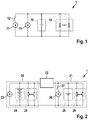
- FIG. 2 shows a vehicle electrical system 1 with a high-voltage sub-network 20 and a low-voltage sub-network 21 and a unidirectional, potential-separating DC / DC converter 22, which forms a coupling unit between the high voltage sub-network 20 and the low voltage sub-network 21.
- the electrical system 1 may be a vehicle electrical system of a vehicle, in particular a motor vehicle, transport vehicle or forklift.
- the high-voltage sub-network 20 is, for example, a 48-volt electrical system with an electric generator 23 which is operable by an internal combustion engine (not shown).
- the generator 23 is formed in this embodiment, in response to a rotational movement of the engine of the vehicle to generate electrical energy and feed it into the high-voltage sub-network 20.
- the high voltage sub-network 20 further comprises a battery 24, which may be used as, for example a lithium-ion battery may be formed and which is adapted to output the necessary operating voltage to the high voltage subnet.
- load resistors 25 are arranged, which may be formed for example by at least one, preferably by a plurality of electrical consumers of the motor vehicle, which are operated with the high voltage.
- the low-voltage sub-network 21 which is arranged on the output side of the DC / DC converter 22, there are a starter 26, which is set to close a switch 27 to start the engine, and an energy storage 28, which is set, the low voltage in Level of, for example, 14 volts for the low voltage subnetwork 21.
- the low-voltage sub-network 21 further consumers 29 are arranged, which are operated with the low voltage.
- the vehicle electrical system voltage in the low-voltage sub-network 21 is in driving operation, depending on the temperature and state of charge of the energy storage device 28, approximately in the range between 10.8 volts and 15 volts.
- the DC / DC converter 22 is connected on the input side to the high-voltage sub-network 20 and to the generator 23.
- the DC / DC converter 22 is connected on the output side to the low-voltage sub-network 21.
- the DC / DC converter 22 is designed to receive a DC voltage received on the input side, for example a DC voltage with which the high-voltage subnetwork is operated, for example between 12 and 48 volts, and to generate an output voltage which is different from the voltage received on the input side, in particular to produce an output voltage which is smaller than the voltage received on the input side, for example 12 V or 14 V.
- FIG. 3 shows a vehicle electrical system 1 with a high voltage sub-network 20 and a low voltage sub-network 21, which are connected by a bidirectional, potential-separating DC / DC converter 31.
- the illustrated vehicle electrical system 1 is essentially the same as that in FIG. 2 formed electrical system, wherein the generator is integrated in the high voltage subnet and for the energy transfer between the sub-board networks 20, 21, a DC / DC converter 31 is used, which is designed to isolate potential.
- both sub-networks 20, 21 are also batteries 24, 28 and consumers 25, 29 arranged, as with reference to FIG. 2 described. In essence, that differs in FIG. 3 illustrated system by the involvement of the starter. While in the in FIG.
- the DC / DC converter 22 can be unidirectionally designed for energy transport from the high voltage sub-network 20 in the low voltage subnet 21, is in the in FIG. 3 architecture shown a starter generator 30 in the high voltage sub-network 20 used.
- the DC / DC converter 31 is bidirectional, so that the lithium-ion battery 24 can be charged via the low-voltage sub-network 21, if necessary. The jump start of the low-voltage vehicle then takes place via the low-voltage interface and the DC / DC converter 31.
- FIG. 4 shows a vehicle electrical system 1 with a high-voltage sub-network 20 and a low-voltage sub-network 21, for example, a vehicle electrical system 1 of a vehicle, in particular a motor vehicle, transport vehicle or forklift.
- the electrical system 1 is particularly suitable for use in vehicles with a 48-volt generator, a 14-volt starter and a boost recuperation system.
- the high voltage sub-network 20 includes a generator 23 which is operable by an internal combustion engine (not shown).
- the generator 23 is designed to generate electrical energy as a function of a rotational movement of the engine of the vehicle and to feed it into the high-voltage sub-network 20.
- load resistors 25 are arranged, which may be formed for example by at least one, preferably by a plurality of electrical consumers of the motor vehicle, which are operated with the high voltage.
- the high voltage sub-network 20 also includes a battery 40, which may be formed, for example, as a lithium-ion battery and which is adapted to output the operating voltage of 48 volts the high voltage subnet.
- the lithium-ion battery 40 preferably has a minimum capacity of approximately 15 Ah at a rated voltage of 48 volts in order to be able to store the required electrical energy.
- the battery 40 has a plurality of battery units 41-1, 41-2,... 41-n, wherein the battery units 41 are assigned a plurality of battery cells, which are usually in series and partially additionally connected in parallel with each other to achieve the required power and energy data with the battery 40.
- the individual battery cells are, for example, lithium-ion batteries with a voltage range of 2.8 to 4.2 volts.
- the battery units 41-1, 41-2,... 41-n are assigned individual voltage taps 42-1, 42-2,... 42-n + 1, via which the voltage is supplied to a coupling unit 33.
- the Einzelwoodsabgriffe 42 are disposed between the battery units 41, and at the ends of the battery 40 each one. With a number of n battery units, this results in n + 1 taps 42.
- the additional Einzelpressivesabgriffe 42 the lithium-ion battery 40 is divided into a plurality of battery units 41-1, 41-2, ... 41-n, which in the context The invention may also be referred to as sub-batteries.
- the individual voltage taps 42 are selected such that the battery units 41 each have a voltage position with which the low-voltage subnetwork 21, ie the 14-volt vehicle electrical system, can be supplied.
- the Einzelwoodsabgriffe 42 of the battery units 41 as in FIG. 4 shown, the coupling unit 33 is supplied.
- the coupling unit 33 has the task of switching on at least one of the battery units 41 of the battery 40 to the low voltage subnet 21 for its operation or support.
- the coupling unit 33 couples the high-voltage sub-network 20 with the low-voltage sub-network 21 and provides the output voltage to the low-voltage sub-network 21, for example 12 V or 14 V.
- the structure and mode of operation of the coupling unit 33 are described with reference to FIGS FIGS. 5 to 7 described.
- the low-voltage sub-network 21 includes the low-voltage consumers 29, which are designed, for example, for operation at 14 V voltage.
- the low voltage subnetwork 21 also includes the starter 26, which is configured to actuate the switch 27 to start the engine.
- a further energy store 28 is available in the low-voltage sub-network 21.
- the energy storage device 28 for example a battery, can provide very high currents for a short time and relieves the lithium-ion battery 40 in the startup phases. Especially the effects of the known weakness of lithium-ion batteries that they are not high Can deliver currents at low temperatures are through the use of energy storage 28 in the in FIG. 4 shown reduced system.
- the starting currents can also be in high total number over the entire life of the battery and even at individual startups possibly several times in succession, ie in case of unsuccessful attempt to start after the recharging of the power storage.
- I max is the maximum on-board electrical system current that can flow during the switching operations in the electrical system
- ⁇ U max the maximum permissible change of the vehicle electrical system voltage during the switching operation.
- the lithium-ion battery 40 takes over the supply of closed-circuit consumers, which are shown as consumers 25, 29, when the vehicle is parked.
- closed-circuit consumers which are shown as consumers 25, 29, when the vehicle is parked.
- the requirements of the so-called airport tests are met, wherein after six weeks of service the vehicle is still bootable and the battery provides the quiescent currents of the low-voltage consumers 29 in the low voltage subnet 21 during the service life, so that, for example, an anti-theft alarm system is supplied.
- the battery management system comprises a control unit which is set up to acquire and process measurement data on temperatures, voltages provided, discharged currents and charge states of the battery 40 or of the battery units 41, and to make statements about the health status of the battery 40, for example.
- the battery management system includes In this case, a unit which is set up to control the coupling unit 33 so that it can selectively connect the battery units 41 in the low-voltage sub-network 21.
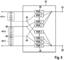
- FIG. 5 shows a coupling unit 33, which is designed as a unidirectional, galvanically non-separating DC-DC converter (DC / DC converter).
- the coupling unit 33 comprises reverse blocking switches 44, 45, which have the property that in a state "on” they allow current to flow in only one direction and in a second state “off” they can absorb a blocking voltage of both polarities.
- This is an essential difference to simple semiconductor switches, such as IGBT switches, since they can not absorb reverse voltage in the reverse direction due to their intrinsic diode. Due to the dependence on the current flow direction are in FIG. 5 Two different types of switches are shown, namely RSS_l 45 and RSS_r 44, which do not differ in their production, but are only installed with different polarity.
- An example of the structure of the reverse blocking switches 44, 45 will be described with reference to FIG FIG. 8 described.
- the individual voltage taps 42 of the battery units 41 are each branched at branching points 43 and supplied to one of the different reverse blocking switches RSS_l 45 and RSS_r 44, respectively.
- the reverse blocking switch RSS_l 45 are the output side of the coupling unit 33 connected to the positive pole 52
- the reverse blocking switch RSS_r 44 are the output side of the coupling unit 33 connected to the negative pole 51.
- FIG. 6 shows the supply of the low voltage sub-network 21 by way of example from the battery unit 41-2 via the associated taps 42-2 and 42-3.
- the current path 61 leads via a reverse blocking switch RSS_l 45-i via a branch point 43-i via the voltage tap 42-2 to the through-connected battery unit 41-2, and from there via the voltage tap 42 arranged after the through-connected battery unit 41-2 -3 via the branch point 43-j via a further reverse blocking switch RSS_r 44-i to the negative pole 51.
- At the first branch point 43-i also leads to a connection to another reverse blocking switch RSS_r 44-j. Since this is formed backward blocking, but no current can flow here.
- the voltage level of the high-voltage sub-network 20 relative to the ground of the low-voltage sub-network 21 depends on which of the battery units 41 is switched on. However, in none of the operating conditions does one of the potentials have an amount exceeding a voltage limit equal to the sum of the high voltage and the low voltage, i. at a 48 volt mains and a 14 volt mains at about 62 volts. However, negative potentials can occur with respect to the ground of the low voltage subnetwork.
- the operation of the high voltage generator 23 is independent of the operation of the coupling unit 33 and the supply of the low voltage subnet.
- the through-connected battery unit 41 which supplies the low-voltage sub-network 21 results in an overlay by the low-voltage sub-network power and possibly fed by the generator 23 in the entire lithium-ion battery 40 charging current (generator mode) or by the entire lithium-ion Battery 40 discharged discharge current (motor operation).
- the allowable limits of the battery cells e.g. the maximum allowable discharge current of the cells are not exceeded, these processes can be considered independently.
- the low voltage subnet 21 is supplied safely, exactly one of the battery units 41 via the associated switches 44, 45 of the coupling device 33 is switched on. Due to the multiple redundant supply of the low voltage subnetwork 21, a system can be constructed with the architecture presented, which has a very high availability of electrical energy in the low voltage subnet.
- FIG. 7 shows a switching operation by means of the coupling unit 33 by way of example from the battery unit 41-1 to the battery unit 41-n.
- a first current path 71 leads via a first reverse blocking switch RSS_l 45-i, via first voltage taps 42-1, 42-2 associated with the first battery unit 41-1, and via a second reverse blocking switch RSS_r 44-i Negative pole 51.
- the current path 72 leads via a second reverse blocking switch RSS_l 45-k, via voltage taps 42-n, 42-n + 1, which are assigned to the nth battery unit 41-n, and via another reverse blocking switch RSS_r 44-k to the negative pole 51.
- the maximum achievable power is limited by uniformly aged cells by that cell with the lowest charge state.
- the maximum removable energy is limited by evenly charged cells by the cell with the lowest state of charge.
- the maximum allowable load performance is limited by the cell with the highest state of charge for evenly aged cells.
- the maximum deliverable energy is limited by evenly aged cells by the cell with the highest state of charge.
- the battery system in a boost recuperation system should be able to store as much energy as possible during a braking process at the same time as being able to support a boost process as well as possible, the requirement can be derived from this the battery units 41 and the cells therein must all have the same possible state of charge in order to meet the requirements as well as possible.
- the requirements for the selection of the switching states of the coupling unit 33 can be met with the following operating strategy:
- the supply of the low voltage subnet 21 always takes place from that sub-battery 41, which currently has the highest state of charge. Since the supply of the low voltage subnetwork is superimposed on the charging and discharging in the high voltage subnet and the low voltage subnetwork unidirectional, is ensured by this selection rule that the sub-battery 41 is discharged faster with the highest state of charge or is charged slower than the other battery units 41. Dies has a symmetrization of the charge states of the sub-batteries result.
- a threshold value for the difference .DELTA.SOC switching of the charge states is introduced, eg a difference .DELTA.SOC switching with a defined value between 0.5% and 20 %, preferably between 1% and 5%, more preferably about 2%, which must be exceeded, so that the supply of the Low voltage sub-network 21 of a battery unit 41 to that battery unit 41 changes, which has a correspondingly higher state of charge than the currently used to supply the low voltage subnet 21 battery unit 41.
- the switching in the supply is always on that battery unit 41, which currently has the highest state of charge and switching takes place when the current through-connected to supply the low voltage network portion 21 battery unit 41 has a state of charge is at least .DELTA.SOC Shift lower than the state of charge of that battery pack 41 to the highest state of charge.
- FIG. 8 shows a possible construction of reverse blocking switches 44, 45.
- the forward direction is indicated by I.
- a reverse inhibit switch RSS_r 44 comprises, for example, an IGBT, MOSFET or bipolar transistor 101 and a series connected diode 103.
- a MOSFET 101 is shown which has an intrinsic diode 102 shown with.
- the diode 103 connected in series with the MOSFET 101 is poled against the direction of the intrinsic diode 102 of the MOSFET 101.
- the reverse blocking switch RSS_r 44 passes the current in the forward direction I and blocks in the opposite direction.
- the reverse blocking switch RSS_l 45 corresponds to the RSS_r 44, is installed only with the reverse polarity, so that the pass and reverse directions are reversed.
- the switches RSS_l 45, RSS_r 44 are characterized in particular by a barely noticeable delay in the switching operations, ie allow a very short switching time.
- the time delay between switching off and switching on the switches can be set very precisely.
Landscapes
- Engineering & Computer Science (AREA)
- Mechanical Engineering (AREA)
- Power Engineering (AREA)
- Transportation (AREA)
- Life Sciences & Earth Sciences (AREA)
- Sustainable Energy (AREA)
- Sustainable Development (AREA)
- Chemical & Material Sciences (AREA)
- Combustion & Propulsion (AREA)
- Automation & Control Theory (AREA)
- Charge And Discharge Circuits For Batteries Or The Like (AREA)
- Electric Propulsion And Braking For Vehicles (AREA)
- Secondary Cells (AREA)
Claims (9)
- Réseau de bord (1) destiné à un véhicule automobile, le réseau de bord comprenant un sous-réseau à basse tension (21), destiné à au moins un consommateur à basse tension (29), et un sous-réseau à haute tension (20), destiné à au moins un consommateur à haute tension (25), et un générateur électrique (23), le sous-réseau à haute tension (20) étant relié au sous-réseau à basse tension (21) par le biais d'une unité de couplage (33) qui est conçue pour prendre de l'énergie au sous-réseau à haute tension (20) et l'acheminer au sous-réseau à basse tension (21), le sous-réseau à haute tension (20) comprenant une batterie (40) qui est conçue pour générer la haute tension et la délivrer au sous-réseau à haute tension (20) et qui comprend au moins deux unités de batterie (41) munies de prises de tension simples (42) qui sont amenées à l'unité de couplage (33), l'unité de couplage (33) étant conçue pour connecter sélectivement les unités de batterie (41) au sous-réseau à basse tension (21), et le sous-réseau à basse tension (21) comprenant au moins un autre accumulateur d'énergie (28) qui est conçu pour générer la basse tension et la délivrer au sous-réseau à basse tension (21), caractérisé en ce qu'un processus de commutation est effectué à des instants où le courant du réseau de bord est le plus faible possible et une synchronisation avec un système de gestion de consommation est effectuée pour déconnecter brièvement les consommateurs de forte puissance afin de permettre le processus de commutation sans baisse de tension significative.
- Réseau de bord (1) selon la revendication 1, caractérisé en ce que les unités de batterie (41) connectables sélectivement sont chacune conçues pour produire la basse tension.
- Réseau de bord (1) selon l'une des revendications précédentes, caractérisé en ce que l'unité de couplage (33) comprend des commutateurs (44, 45) blocables en inverse.
- Réseau de bord (1) selon l'une des revendications précédentes, caractérisé en ce que le sous-réseau à basse tension (21) comprend un démarreur (26).
- Procédé de fonctionnement d'un réseau de bord (1) destiné à un véhicule automobile,
le réseau de bord (1) comprenant un sous-réseau à basse tension (21), destiné à au moins un consommateur à basse tension (29), et un sous-réseau à haute tension (20), destiné à au moins un consommateur à haute tension (25), et un générateur électrique (23), le sous-réseau à haute tension (20) étant relié au sous-réseau à basse tension (21) par le biais d'une unité de couplage (33) qui est conçue pour prendre de l'énergie au sous-réseau à haute tension (20) et l'acheminer au sous-réseau à basse tension (21), le sous-réseau à haute tension (20) comprenant une batterie (40) qui est conçue pour générer la haute tension et la délivrer au sous-réseau à haute tension (20) et qui comprend au moins deux unités de batterie (41) munies de prises de tension simples (42) qui sont amenées à l'unité de couplage (33), l'unité de couplage (33) étant conçue pour connecter sélectivement les unités de batterie (41) au sous-réseau à basse tension (21), et le sous-réseau à basse tension (21) comprenant au moins un autre accumulateur d'énergie (28) qui est conçu pour générer la basse tension et la délivrer au sous-réseau à basse tension (21), caractérisé en ce que l'unité de batterie (41) qui est connectée au sous-réseau à basse tension (21) est celle qui présente l'état de charge le plus élevé, un changement d'unité de batterie connectée (41) étant effectué à des instants où le courant de réseau de bord est le plus faible possible et une synchronisation avec un système de gestion de consommateurs est effectuée pour déconnecter brièvement des consommateurs de grande puissance afin de permettre la commutation sans baisse de tension significative car une unité de batterie (41) conductrice de courant étant déconnectée dans une première étape, puis une autre unité de batterie sélectionnée (41) étant connectée dans une deuxième étape, et la basse tension étant stabilisée par le stockage d'énergie (28) lors d'un changement d'unité de batterie connectée (41). - Procédé selon la revendication 5, caractérisé en ce qu'un changement d'unité de batterie connectée (41) est effectué lorsqu'une valeur seuil d'une différence d'état de charge des unités de batterie (41) est franchie vers le haut.
- Système de gestion de batterie destinée à la mise en oeuvre de l'un des procédés selon l'une des revendications 5 et 6, ledit système comprenant une unité de détermination de l'état de charge d'unités de batterie (41) et une unité de commande d'une unité de couplage (33) pour connecter sélectivement des unités de batterie (41) en fonction d'états de charge des unités de batterie (41).
- Logiciel conçu pour mettre en oeuvre l'un des procédés selon l'une des revendications 5 à 7, lorsque le logiciel est exécuté sur un équipement informatique programmable.
- Véhicule automobile comprenant un moteur à combustion interne et un réseau de bord (1) selon l'une des revendications 1 à 4.
Applications Claiming Priority (2)
| Application Number | Priority Date | Filing Date | Title |
|---|---|---|---|
| DE102014201345.3A DE102014201345A1 (de) | 2014-01-27 | 2014-01-27 | Bordnetz und Verfahren zum Betrieb eines Bordnetzes |
| PCT/EP2015/051325 WO2015110566A1 (fr) | 2014-01-27 | 2015-01-23 | Réseau de bord et procédé pour faire fonctionner un réseau de bord |
Publications (2)
| Publication Number | Publication Date |
|---|---|
| EP3100334A1 EP3100334A1 (fr) | 2016-12-07 |
| EP3100334B1 true EP3100334B1 (fr) | 2019-08-21 |
Family
ID=52434784
Family Applications (1)
| Application Number | Title | Priority Date | Filing Date |
|---|---|---|---|
| EP15701751.8A Active EP3100334B1 (fr) | 2014-01-27 | 2015-01-23 | Réseau de bord et procédé pour faire fonctionner un réseau de bord |
Country Status (6)
| Country | Link |
|---|---|
| US (1) | US10071646B2 (fr) |
| EP (1) | EP3100334B1 (fr) |
| KR (1) | KR102000237B1 (fr) |
| CN (1) | CN105934866A (fr) |
| DE (1) | DE102014201345A1 (fr) |
| WO (1) | WO2015110566A1 (fr) |
Families Citing this family (18)
| Publication number | Priority date | Publication date | Assignee | Title |
|---|---|---|---|---|
| DE102015218714A1 (de) | 2015-09-29 | 2017-03-30 | Continental Automotive Gmbh | Stromversorgungsschaltung zur Versorgung eines Fahrzeugbordnetzes mit elektrischer Energie und Fahrzeugbordnetz |
| US9908419B2 (en) | 2015-11-24 | 2018-03-06 | GM Global Technology Operations LLC | Method and apparatus for controlling a DC/DC power converter |
| DE102015120285B4 (de) * | 2015-11-24 | 2020-12-24 | Auto-Kabel Management Gmbh | Batterie, Fahrzeug mit einer solchen Batterie und Verwendung einer solchen Batterie |
| US9973032B2 (en) | 2015-12-04 | 2018-05-15 | Google Llc | Two-tier battery solution for data center backup |
| CN205554092U (zh) * | 2016-04-14 | 2016-09-07 | 罗伯特·博世有限公司 | Dc/dc转换器、电池能量管理系统及混合动力车辆 |
| DE102017100138A1 (de) * | 2017-01-05 | 2018-07-05 | Envia Mitteldeutsche Energie Ag | Verfahren zum Betreiben eines Teilnehmers an einem Versorgungsnetz |
| EP3360719B1 (fr) * | 2017-02-09 | 2020-09-09 | Samsung SDI Co., Ltd | Système d'alimentation électrique double |
| CN106953344A (zh) * | 2017-05-02 | 2017-07-14 | 深圳市虹鹏能源科技有限责任公司 | 一种地铁机车制动能量回收系统 |
| EP3398818B1 (fr) * | 2017-05-04 | 2022-07-06 | Volvo Car Corporation | Unité d'alimentation en tension et procédé d'équilibrage de batterie |
| DE102017220805A1 (de) * | 2017-11-22 | 2019-05-23 | Robert Bosch Gmbh | Fahrzeugvorrichtung und Verfahren zum Betrieb einer Fahrzeugvorrichtung |
| JP7204376B2 (ja) * | 2018-08-21 | 2023-01-16 | 株式会社Subaru | バッテリ管理システム |
| DE102019129170A1 (de) * | 2019-10-29 | 2021-04-29 | Volkswagen Aktiengesellschaft | Steuerungsanordnung für eine Hochvoltbatterie und Verfahren zum Betreiben einer Steuerungsanordnung |
| DE102020204891A1 (de) | 2020-04-17 | 2021-10-21 | Zf Friedrichshafen Ag | Leistungsverteilunssystem |
| CN112165131A (zh) * | 2020-09-07 | 2021-01-01 | 东风柳州汽车有限公司 | 一种新能源汽车应急供电系统、启动控制方法 |
| US11945326B2 (en) * | 2020-12-18 | 2024-04-02 | Preh Gmba | Method and charging device for charging a high-voltage battery of an electric vehicle |
| DE102021101601A1 (de) | 2021-01-26 | 2022-07-28 | Audi Aktiengesellschaft | Bordnetz für ein Kraftfahrzeug und Kraftfahrzeug |
| DE102021101600A1 (de) | 2021-01-26 | 2022-07-28 | Audi Aktiengesellschaft | Bordnetz für ein Kraftfahrzeug, Kraftfahrzeug und Verfahren zum Betrieb eines Bordnetzes |
| DE102021124184A1 (de) | 2021-09-20 | 2023-03-23 | Bayerische Motoren Werke Aktiengesellschaft | Verfahren und Vorrichtung zum Starten eines Energiewandlers |
Citations (8)
| Publication number | Priority date | Publication date | Assignee | Title |
|---|---|---|---|---|
| WO2001037393A1 (fr) * | 1999-11-16 | 2001-05-25 | Johnson Controls Technology Company | Convertisseur continu-continu reversible a semi-conducteurs |
| DE10057259A1 (de) * | 2000-11-18 | 2002-05-23 | Bosch Gmbh Robert | Mehrspannungsbordnetz für ein Kraftfahrzeug |
| EP1562252A1 (fr) * | 2004-02-05 | 2005-08-10 | Ford Global Technologies, LLC, A subsidary of Ford Motor Company | Système d'alimentation en énergie |
| EP2053717A2 (fr) * | 2007-10-23 | 2009-04-29 | Honda Motor Co., Ltd. | Contrôleur de décharges |
| DE102009028147A1 (de) * | 2009-07-31 | 2011-02-03 | Robert Bosch Gmbh | Schaltungsanordnung für ein Bordnetz |
| EP2496437A2 (fr) * | 2009-11-05 | 2012-09-12 | Toyota Jidosha Kabushiki Kaisha | Unité d'alimentation électrique pour véhicule et son procédé de commande |
| DE102012010711A1 (de) * | 2012-05-30 | 2013-03-28 | Daimler Ag | Bordnetzanordnung für ein Fahrzeug und Verfahren zu deren Betrieb |
| DE102012003309A1 (de) * | 2012-02-18 | 2013-08-22 | Volkswagen Aktiengesellschaft | Elektrisches Energiesystem in einem Kraftfahrzeug und Verfahren zum Betreiben eines Energiesystems |
Family Cites Families (51)
| Publication number | Priority date | Publication date | Assignee | Title |
|---|---|---|---|---|
| US5397991A (en) * | 1988-07-13 | 1995-03-14 | Electronic Development Inc. | Multi-battery charging system for reduced fuel consumption and emissions in automotive vehicles |
| US5602459A (en) * | 1988-07-13 | 1997-02-11 | Electronic Development Inc. | Fuel saving multi-battery charging system and method |
| AU669853B2 (en) * | 1991-08-01 | 1996-06-27 | Ea Technology Limited | Battery powered electric vehicle and electrical supply system |
| US5345154A (en) * | 1993-02-26 | 1994-09-06 | General Electric Company | Electric continuously variable transmission and controls for operation of a heat engine in a closed-loop power-control mode |
| US5710699A (en) * | 1996-05-28 | 1998-01-20 | General Electric Company | Power electronic interface circuits for batteries and ultracapacitors in electric vehicles and battery storage systems |
| JPH11280512A (ja) * | 1998-03-30 | 1999-10-12 | Nissan Motor Co Ltd | ハイブリッド車両 |
| US6554088B2 (en) * | 1998-09-14 | 2003-04-29 | Paice Corporation | Hybrid vehicles |
| US6331365B1 (en) * | 1998-11-12 | 2001-12-18 | General Electric Company | Traction motor drive system |
| US20060005739A1 (en) * | 2001-03-27 | 2006-01-12 | Kumar Ajith K | Railroad system comprising railroad vehicle with energy regeneration |
| KR20040074783A (ko) * | 2003-02-19 | 2004-08-26 | 현대자동차주식회사 | 하이브리드 전기 자동차의 전원장치 및 그것의 제어방법 |
| US6832148B1 (en) * | 2003-10-14 | 2004-12-14 | General Motors Corporation | Automatic engine stop and restart mode for reducing emissions of a hybrid electric vehicle |
| US7127337B2 (en) * | 2003-10-14 | 2006-10-24 | General Motors Corporation | Silent operating mode for reducing emissions of a hybrid electric vehicle |
| US7349797B2 (en) * | 2004-03-30 | 2008-03-25 | Railpower Technologies Corp | Emission management for a hybrid locomotive |
| US7176648B2 (en) * | 2004-05-18 | 2007-02-13 | Husky Injection Molding Systems Ltd. | Energy management apparatus and method for injection molding systems |
| US7866425B2 (en) * | 2004-06-28 | 2011-01-11 | General Electric Company | Hybrid electric propulsion system and method |
| JP4291235B2 (ja) * | 2004-08-20 | 2009-07-08 | 株式会社日立製作所 | 車両用電源装置 |
| JP2006304393A (ja) * | 2005-04-15 | 2006-11-02 | Toyota Motor Corp | 電源装置およびその制御方法並びに車両 |
| DE102005038746A1 (de) * | 2005-08-16 | 2007-03-01 | Ford-Werke Gmbh | Verfahren und Vorrichtung zur Spannungsversorgung in einem Kraftfahrzeug |
| JP4561616B2 (ja) * | 2005-10-27 | 2010-10-13 | トヨタ自動車株式会社 | モータ駆動システム |
| DE102005056232A1 (de) * | 2005-11-25 | 2007-05-31 | Bayerische Motoren Werke Ag | Mehrspannungsbordnetz für ein Kraftfahrzeug und Verfahren zum Betrieb desselben |
| US7595597B2 (en) * | 2006-01-18 | 2009-09-29 | General Electric Comapany | Vehicle propulsion system |
| US20080121136A1 (en) * | 2006-11-28 | 2008-05-29 | General Electric Company | Hybrid locomotive and method of operating the same |
| JP4221494B2 (ja) * | 2007-03-29 | 2009-02-12 | トヨタ自動車株式会社 | ハイブリッド車両の制御装置 |
| JP4363478B2 (ja) * | 2007-10-29 | 2009-11-11 | トヨタ自動車株式会社 | 燃料電池の出力制御装置 |
| DE102008002177A1 (de) * | 2008-06-03 | 2009-12-10 | Robert Bosch Gmbh | Mehrere Teilbordnetze umfassendes Bordnetz mit Spannungswandler |
| KR100951979B1 (ko) * | 2008-07-08 | 2010-04-08 | 현대자동차주식회사 | 마일드 하이브리드 차량의 이중 전원 시스템 |
| US8063609B2 (en) * | 2008-07-24 | 2011-11-22 | General Electric Company | Method and system for extending life of a vehicle energy storage device |
| WO2010125628A1 (fr) * | 2009-04-27 | 2010-11-04 | トヨタ自動車株式会社 | Voiture hybride et procédé de commande associé |
| US8909399B2 (en) * | 2009-05-25 | 2014-12-09 | Toyota Jidosha Kabushiki Kaisha | Hybrid vehicle and control method thereof |
| US8442727B2 (en) * | 2009-06-05 | 2013-05-14 | Toyota Jidosha Kabushiki Kaisha | Electric vehicle and method for setting total allowable discharge electric energy in the electric vehicle |
| DE102009024345A1 (de) * | 2009-06-09 | 2011-01-20 | Lisa Dräxlmaier GmbH | Schaltungsanordnung und Steuerverfahren zur Spannungsstützung eines Bordnetzes eines Fahrzeugs |
| US8916993B2 (en) * | 2009-08-11 | 2014-12-23 | General Electric Company | System for multiple energy storage and management and method of making same |
| DE102009029417A1 (de) * | 2009-09-14 | 2011-03-24 | Robert Bosch Gmbh | Verfahren und Vorrichtung zum Betreiben eines Hybridfahrzeuges beim Defekt eines Energiesystems |
| DE102009046305A1 (de) * | 2009-11-03 | 2011-05-05 | Robert Bosch Gmbh | Niedervolt-Spannungsversorgung |
| DE102009046553A1 (de) * | 2009-11-10 | 2011-05-12 | Robert Bosch Gmbh | Schaltungsanordnung zur Umwandlung einer Spannung von einem ersten auf ein zweites Spannungsniveau und Bordnetz für ein Kraftfahrzeug |
| CN102781713B (zh) * | 2010-01-21 | 2015-12-02 | 电子能量发动机系统有限责任公司 | 碳氢燃料电系列混合推进系统 |
| US9971865B2 (en) * | 2010-03-01 | 2018-05-15 | GM Global Technology Operations LLC | Method for operating a hybrid vehicle |
| US8602141B2 (en) * | 2010-04-05 | 2013-12-10 | Daimler Trucks North America Llc | Vehicle power system with fuel cell auxiliary power unit (APU) |
| DE102010014104A1 (de) * | 2010-04-07 | 2011-10-13 | Dbk David + Baader Gmbh | Elektrisches Energiebordnetz für ein Kraftfahrzeug |
| JP5389730B2 (ja) * | 2010-05-14 | 2014-01-15 | 株式会社デンソー | 電力変換システムの放電装置 |
| JP5553385B2 (ja) * | 2010-09-02 | 2014-07-16 | オムロンオートモーティブエレクトロニクス株式会社 | 電源制御装置 |
| US8355833B2 (en) * | 2010-12-02 | 2013-01-15 | Gm Global Technology Operations, Llc | Systems and methods for controlling engine torque |
| JP5788990B2 (ja) * | 2010-12-22 | 2015-10-07 | ボルボ トラック コーポレイション | ハイブリッド原動機アセンブリの制御方法及び当該方法に従って制御されるハイブリッド車 |
| FR2972581B1 (fr) * | 2011-03-09 | 2015-01-02 | Commissariat Energie Atomique | Systeme d'equilibrage de charge pour batteries |
| JP5698615B2 (ja) * | 2011-06-28 | 2015-04-08 | 矢崎総業株式会社 | 混成回路 |
| US9789764B2 (en) * | 2012-03-07 | 2017-10-17 | International Truck Intellectual Property Company, Llc | Vehicle electrical system state controller |
| JP2014014226A (ja) * | 2012-07-04 | 2014-01-23 | Toshiba Mitsubishi-Electric Industrial System Corp | 交流電動機駆動装置 |
| JP5751240B2 (ja) * | 2012-11-07 | 2015-07-22 | トヨタ自動車株式会社 | 交流電動機の制御システム |
| US9162669B2 (en) * | 2014-02-25 | 2015-10-20 | Cummins Inc. | Systems and methods for control of powertrains with regenerative start/stop alternator functionality |
| JP2015204639A (ja) * | 2014-04-10 | 2015-11-16 | トヨタ自動車株式会社 | 電力変換装置及びその制御方法 |
| US9789771B2 (en) * | 2015-04-24 | 2017-10-17 | GM Global Technology Operations LLC | Single battery architecture for electrification vehicle |
-
2014
- 2014-01-27 DE DE102014201345.3A patent/DE102014201345A1/de not_active Ceased
-
2015
- 2015-01-23 EP EP15701751.8A patent/EP3100334B1/fr active Active
- 2015-01-23 WO PCT/EP2015/051325 patent/WO2015110566A1/fr active Application Filing
- 2015-01-23 CN CN201580005804.3A patent/CN105934866A/zh active Pending
- 2015-01-23 KR KR1020167023428A patent/KR102000237B1/ko active IP Right Grant
- 2015-01-23 US US15/114,550 patent/US10071646B2/en active Active
Patent Citations (8)
| Publication number | Priority date | Publication date | Assignee | Title |
|---|---|---|---|---|
| WO2001037393A1 (fr) * | 1999-11-16 | 2001-05-25 | Johnson Controls Technology Company | Convertisseur continu-continu reversible a semi-conducteurs |
| DE10057259A1 (de) * | 2000-11-18 | 2002-05-23 | Bosch Gmbh Robert | Mehrspannungsbordnetz für ein Kraftfahrzeug |
| EP1562252A1 (fr) * | 2004-02-05 | 2005-08-10 | Ford Global Technologies, LLC, A subsidary of Ford Motor Company | Système d'alimentation en énergie |
| EP2053717A2 (fr) * | 2007-10-23 | 2009-04-29 | Honda Motor Co., Ltd. | Contrôleur de décharges |
| DE102009028147A1 (de) * | 2009-07-31 | 2011-02-03 | Robert Bosch Gmbh | Schaltungsanordnung für ein Bordnetz |
| EP2496437A2 (fr) * | 2009-11-05 | 2012-09-12 | Toyota Jidosha Kabushiki Kaisha | Unité d'alimentation électrique pour véhicule et son procédé de commande |
| DE102012003309A1 (de) * | 2012-02-18 | 2013-08-22 | Volkswagen Aktiengesellschaft | Elektrisches Energiesystem in einem Kraftfahrzeug und Verfahren zum Betreiben eines Energiesystems |
| DE102012010711A1 (de) * | 2012-05-30 | 2013-03-28 | Daimler Ag | Bordnetzanordnung für ein Fahrzeug und Verfahren zu deren Betrieb |
Also Published As
| Publication number | Publication date |
|---|---|
| US10071646B2 (en) | 2018-09-11 |
| CN105934866A (zh) | 2016-09-07 |
| EP3100334A1 (fr) | 2016-12-07 |
| KR20160114133A (ko) | 2016-10-04 |
| DE102014201345A1 (de) | 2015-07-30 |
| US20160347197A1 (en) | 2016-12-01 |
| KR102000237B1 (ko) | 2019-07-15 |
| WO2015110566A1 (fr) | 2015-07-30 |
Similar Documents
| Publication | Publication Date | Title |
|---|---|---|
| EP3100334B1 (fr) | Réseau de bord et procédé pour faire fonctionner un réseau de bord | |
| EP3134949B1 (fr) | Réseau de bord | |
| WO2015110570A1 (fr) | Réseau de bord et procédé pour faire fonctionner un réseau de bord | |
| DE102014203030B4 (de) | Verfahren zum gesteuerten Verbinden mehrerer Bordnetzzweige eines Fahrzeugs, Steuereinheit zur Ausführung des Verfahrens sowie Fahrzeugbordnetz | |
| WO2015110407A1 (fr) | Procédé pour faire fonctionner un système électrique | |
| WO2015110405A1 (fr) | Système électrique et procédé pour faire fonctionner un système électrique | |
| WO2015110579A1 (fr) | Procédé pour faire fonctionner un réseau de bord | |
| DE102014207390A1 (de) | Bordnetz und Verfahren zum Betrieb eines Bordnetzes | |
| EP3099523A1 (fr) | Réseau de bord et procédé pour faire fonctionner un réseau de bord | |
| EP2897833B1 (fr) | Dispositif accumulateur de couplage pour véhicule | |
| EP2822808B1 (fr) | Réseau de bord pour un véhicule | |
| EP2953227A1 (fr) | Réseau de bord pour un véhicule automobile | |
| DE102012206772A1 (de) | Stützspeicher mit Mittenabgriff | |
| WO2016083295A1 (fr) | Système à plusieurs accumulateurs d'énergie pour réseaux de bord de véhicules à moteur | |
| WO2017202537A1 (fr) | Réseau de bord de véhicule à moteur doté d'au moins deux accumulateurs d'énergie, procédé pour faire fonctionner un réseau de bord de véhicule à moteur et moyens pour sa mise en oeuvre | |
| EP3067240B1 (fr) | Procede d'alimentation en tension d'un reseau de bord d'un vehicule automobile | |
| WO2005002904A1 (fr) | Limiteur de surtension conçu pour un convertisseur de courant de traction | |
| DE102012007575B3 (de) | Energiespeicheranordnung | |
| DE102009029335A1 (de) | Lithium-Ionen Batteriesystem für µ-Hybrid-Fahrzeuge | |
| DE102014201360A1 (de) | Bordnetz | |
| DE102014201354A1 (de) | Bordnetz | |
| WO2016180699A1 (fr) | Module de commutation de réseau de bord, dispositif d'assistance de réseau de bord et branche de réseau de bord | |
| EP3268243B1 (fr) | Tampon de puissance pour un système de batterie pour faire fonctionner un moteur électrique et procédé de réglage d'une puissance électrique produite par un système de batterie pour faire fonctionner un moteur électrique | |
| DE102007043919A1 (de) | Lade- und Trennschaltung | |
| DE102010010409A1 (de) | Verfahren zum Betreiben einer Energiespeicheranordnung und Energiespeicheranordnung |
Legal Events
| Date | Code | Title | Description |
|---|---|---|---|
| PUAI | Public reference made under article 153(3) epc to a published international application that has entered the european phase |
Free format text: ORIGINAL CODE: 0009012 |
|
| STAA | Information on the status of an ep patent application or granted ep patent |
Free format text: STATUS: REQUEST FOR EXAMINATION WAS MADE |
|
| 17P | Request for examination filed |
Effective date: 20160829 |
|
| AK | Designated contracting states |
Kind code of ref document: A1 Designated state(s): AL AT BE BG CH CY CZ DE DK EE ES FI FR GB GR HR HU IE IS IT LI LT LU LV MC MK MT NL NO PL PT RO RS SE SI SK SM TR |
|
| AX | Request for extension of the european patent |
Extension state: BA ME |
|
| DAX | Request for extension of the european patent (deleted) | ||
| STAA | Information on the status of an ep patent application or granted ep patent |
Free format text: STATUS: EXAMINATION IS IN PROGRESS |
|
| 17Q | First examination report despatched |
Effective date: 20180202 |
|
| REG | Reference to a national code |
Ref country code: DE Ref legal event code: R079 Ref document number: 502015010054 Country of ref document: DE Free format text: PREVIOUS MAIN CLASS: H02J0007000000 Ipc: B60W0010260000 |
|
| GRAP | Despatch of communication of intention to grant a patent |
Free format text: ORIGINAL CODE: EPIDOSNIGR1 |
|
| STAA | Information on the status of an ep patent application or granted ep patent |
Free format text: STATUS: GRANT OF PATENT IS INTENDED |
|
| RIC1 | Information provided on ipc code assigned before grant |
Ipc: B60L 58/18 20190101ALI20190402BHEP Ipc: B60W 20/13 20160101ALI20190402BHEP Ipc: B60L 58/19 20190101ALI20190402BHEP Ipc: H02J 7/00 20060101ALI20190402BHEP Ipc: B60R 16/033 20060101ALI20190402BHEP Ipc: B60L 58/21 20190101ALI20190402BHEP Ipc: B60W 10/26 20060101AFI20190402BHEP |
|
| INTG | Intention to grant announced |
Effective date: 20190502 |
|
| RAP1 | Party data changed (applicant data changed or rights of an application transferred) |
Owner name: SAMSUNG SDI CO., LTD. Owner name: ROBERT BOSCH GMBH |
|
| GRAS | Grant fee paid |
Free format text: ORIGINAL CODE: EPIDOSNIGR3 |
|
| GRAA | (expected) grant |
Free format text: ORIGINAL CODE: 0009210 |
|
| STAA | Information on the status of an ep patent application or granted ep patent |
Free format text: STATUS: THE PATENT HAS BEEN GRANTED |
|
| AK | Designated contracting states |
Kind code of ref document: B1 Designated state(s): AL AT BE BG CH CY CZ DE DK EE ES FI FR GB GR HR HU IE IS IT LI LT LU LV MC MK MT NL NO PL PT RO RS SE SI SK SM TR |
|
| REG | Reference to a national code |
Ref country code: GB Ref legal event code: FG4D Free format text: NOT ENGLISH |
|
| REG | Reference to a national code |
Ref country code: CH Ref legal event code: EP |
|
| REG | Reference to a national code |
Ref country code: DE Ref legal event code: R096 Ref document number: 502015010054 Country of ref document: DE |
|
| REG | Reference to a national code |
Ref country code: AT Ref legal event code: REF Ref document number: 1169393 Country of ref document: AT Kind code of ref document: T Effective date: 20190915 |
|
| REG | Reference to a national code |
Ref country code: IE Ref legal event code: FG4D Free format text: LANGUAGE OF EP DOCUMENT: GERMAN |
|
| REG | Reference to a national code |
Ref country code: LT Ref legal event code: MG4D |
|
| REG | Reference to a national code |
Ref country code: NL Ref legal event code: MP Effective date: 20190821 |
|
| PG25 | Lapsed in a contracting state [announced via postgrant information from national office to epo] |
Ref country code: NO Free format text: LAPSE BECAUSE OF FAILURE TO SUBMIT A TRANSLATION OF THE DESCRIPTION OR TO PAY THE FEE WITHIN THE PRESCRIBED TIME-LIMIT Effective date: 20191121 Ref country code: BG Free format text: LAPSE BECAUSE OF FAILURE TO SUBMIT A TRANSLATION OF THE DESCRIPTION OR TO PAY THE FEE WITHIN THE PRESCRIBED TIME-LIMIT Effective date: 20191121 Ref country code: NL Free format text: LAPSE BECAUSE OF FAILURE TO SUBMIT A TRANSLATION OF THE DESCRIPTION OR TO PAY THE FEE WITHIN THE PRESCRIBED TIME-LIMIT Effective date: 20190821 Ref country code: FI Free format text: LAPSE BECAUSE OF FAILURE TO SUBMIT A TRANSLATION OF THE DESCRIPTION OR TO PAY THE FEE WITHIN THE PRESCRIBED TIME-LIMIT Effective date: 20190821 Ref country code: LT Free format text: LAPSE BECAUSE OF FAILURE TO SUBMIT A TRANSLATION OF THE DESCRIPTION OR TO PAY THE FEE WITHIN THE PRESCRIBED TIME-LIMIT Effective date: 20190821 Ref country code: HR Free format text: LAPSE BECAUSE OF FAILURE TO SUBMIT A TRANSLATION OF THE DESCRIPTION OR TO PAY THE FEE WITHIN THE PRESCRIBED TIME-LIMIT Effective date: 20190821 Ref country code: SE Free format text: LAPSE BECAUSE OF FAILURE TO SUBMIT A TRANSLATION OF THE DESCRIPTION OR TO PAY THE FEE WITHIN THE PRESCRIBED TIME-LIMIT Effective date: 20190821 Ref country code: PT Free format text: LAPSE BECAUSE OF FAILURE TO SUBMIT A TRANSLATION OF THE DESCRIPTION OR TO PAY THE FEE WITHIN THE PRESCRIBED TIME-LIMIT Effective date: 20191223 |
|
| PG25 | Lapsed in a contracting state [announced via postgrant information from national office to epo] |
Ref country code: ES Free format text: LAPSE BECAUSE OF FAILURE TO SUBMIT A TRANSLATION OF THE DESCRIPTION OR TO PAY THE FEE WITHIN THE PRESCRIBED TIME-LIMIT Effective date: 20190821 Ref country code: LV Free format text: LAPSE BECAUSE OF FAILURE TO SUBMIT A TRANSLATION OF THE DESCRIPTION OR TO PAY THE FEE WITHIN THE PRESCRIBED TIME-LIMIT Effective date: 20190821 Ref country code: AL Free format text: LAPSE BECAUSE OF FAILURE TO SUBMIT A TRANSLATION OF THE DESCRIPTION OR TO PAY THE FEE WITHIN THE PRESCRIBED TIME-LIMIT Effective date: 20190821 Ref country code: IS Free format text: LAPSE BECAUSE OF FAILURE TO SUBMIT A TRANSLATION OF THE DESCRIPTION OR TO PAY THE FEE WITHIN THE PRESCRIBED TIME-LIMIT Effective date: 20191221 Ref country code: RS Free format text: LAPSE BECAUSE OF FAILURE TO SUBMIT A TRANSLATION OF THE DESCRIPTION OR TO PAY THE FEE WITHIN THE PRESCRIBED TIME-LIMIT Effective date: 20190821 Ref country code: GR Free format text: LAPSE BECAUSE OF FAILURE TO SUBMIT A TRANSLATION OF THE DESCRIPTION OR TO PAY THE FEE WITHIN THE PRESCRIBED TIME-LIMIT Effective date: 20191122 |
|
| PG25 | Lapsed in a contracting state [announced via postgrant information from national office to epo] |
Ref country code: TR Free format text: LAPSE BECAUSE OF FAILURE TO SUBMIT A TRANSLATION OF THE DESCRIPTION OR TO PAY THE FEE WITHIN THE PRESCRIBED TIME-LIMIT Effective date: 20190821 |
|
| RAP2 | Party data changed (patent owner data changed or rights of a patent transferred) |
Owner name: ROBERT BOSCH GMBH Owner name: SAMSUNG SDI CO., LTD. |
|
| PG25 | Lapsed in a contracting state [announced via postgrant information from national office to epo] |
Ref country code: IT Free format text: LAPSE BECAUSE OF FAILURE TO SUBMIT A TRANSLATION OF THE DESCRIPTION OR TO PAY THE FEE WITHIN THE PRESCRIBED TIME-LIMIT Effective date: 20190821 Ref country code: DK Free format text: LAPSE BECAUSE OF FAILURE TO SUBMIT A TRANSLATION OF THE DESCRIPTION OR TO PAY THE FEE WITHIN THE PRESCRIBED TIME-LIMIT Effective date: 20190821 Ref country code: PL Free format text: LAPSE BECAUSE OF FAILURE TO SUBMIT A TRANSLATION OF THE DESCRIPTION OR TO PAY THE FEE WITHIN THE PRESCRIBED TIME-LIMIT Effective date: 20190821 Ref country code: EE Free format text: LAPSE BECAUSE OF FAILURE TO SUBMIT A TRANSLATION OF THE DESCRIPTION OR TO PAY THE FEE WITHIN THE PRESCRIBED TIME-LIMIT Effective date: 20190821 Ref country code: RO Free format text: LAPSE BECAUSE OF FAILURE TO SUBMIT A TRANSLATION OF THE DESCRIPTION OR TO PAY THE FEE WITHIN THE PRESCRIBED TIME-LIMIT Effective date: 20190821 |
|
| PG25 | Lapsed in a contracting state [announced via postgrant information from national office to epo] |
Ref country code: IS Free format text: LAPSE BECAUSE OF FAILURE TO SUBMIT A TRANSLATION OF THE DESCRIPTION OR TO PAY THE FEE WITHIN THE PRESCRIBED TIME-LIMIT Effective date: 20200224 Ref country code: CZ Free format text: LAPSE BECAUSE OF FAILURE TO SUBMIT A TRANSLATION OF THE DESCRIPTION OR TO PAY THE FEE WITHIN THE PRESCRIBED TIME-LIMIT Effective date: 20190821 Ref country code: SK Free format text: LAPSE BECAUSE OF FAILURE TO SUBMIT A TRANSLATION OF THE DESCRIPTION OR TO PAY THE FEE WITHIN THE PRESCRIBED TIME-LIMIT Effective date: 20190821 Ref country code: SM Free format text: LAPSE BECAUSE OF FAILURE TO SUBMIT A TRANSLATION OF THE DESCRIPTION OR TO PAY THE FEE WITHIN THE PRESCRIBED TIME-LIMIT Effective date: 20190821 |
|
| REG | Reference to a national code |
Ref country code: DE Ref legal event code: R097 Ref document number: 502015010054 Country of ref document: DE |
|
| PLBE | No opposition filed within time limit |
Free format text: ORIGINAL CODE: 0009261 |
|
| STAA | Information on the status of an ep patent application or granted ep patent |
Free format text: STATUS: NO OPPOSITION FILED WITHIN TIME LIMIT |
|
| PG2D | Information on lapse in contracting state deleted |
Ref country code: IS |
|
| 26N | No opposition filed |
Effective date: 20200603 |
|
| PG25 | Lapsed in a contracting state [announced via postgrant information from national office to epo] |
Ref country code: SI Free format text: LAPSE BECAUSE OF FAILURE TO SUBMIT A TRANSLATION OF THE DESCRIPTION OR TO PAY THE FEE WITHIN THE PRESCRIBED TIME-LIMIT Effective date: 20190821 Ref country code: MC Free format text: LAPSE BECAUSE OF FAILURE TO SUBMIT A TRANSLATION OF THE DESCRIPTION OR TO PAY THE FEE WITHIN THE PRESCRIBED TIME-LIMIT Effective date: 20190821 |
|
| REG | Reference to a national code |
Ref country code: CH Ref legal event code: PL |
|
| GBPC | Gb: european patent ceased through non-payment of renewal fee |
Effective date: 20200123 |
|
| REG | Reference to a national code |
Ref country code: BE Ref legal event code: MM Effective date: 20200131 |
|
| PG25 | Lapsed in a contracting state [announced via postgrant information from national office to epo] |
Ref country code: GB Free format text: LAPSE BECAUSE OF NON-PAYMENT OF DUE FEES Effective date: 20200123 Ref country code: LU Free format text: LAPSE BECAUSE OF NON-PAYMENT OF DUE FEES Effective date: 20200123 |
|
| PG25 | Lapsed in a contracting state [announced via postgrant information from national office to epo] |
Ref country code: CH Free format text: LAPSE BECAUSE OF NON-PAYMENT OF DUE FEES Effective date: 20200131 Ref country code: LI Free format text: LAPSE BECAUSE OF NON-PAYMENT OF DUE FEES Effective date: 20200131 Ref country code: BE Free format text: LAPSE BECAUSE OF NON-PAYMENT OF DUE FEES Effective date: 20200131 |
|
| PG25 | Lapsed in a contracting state [announced via postgrant information from national office to epo] |
Ref country code: IE Free format text: LAPSE BECAUSE OF NON-PAYMENT OF DUE FEES Effective date: 20200123 |
|
| REG | Reference to a national code |
Ref country code: AT Ref legal event code: MM01 Ref document number: 1169393 Country of ref document: AT Kind code of ref document: T Effective date: 20200123 |
|
| PG25 | Lapsed in a contracting state [announced via postgrant information from national office to epo] |
Ref country code: AT Free format text: LAPSE BECAUSE OF NON-PAYMENT OF DUE FEES Effective date: 20200123 |
|
| PG25 | Lapsed in a contracting state [announced via postgrant information from national office to epo] |
Ref country code: MT Free format text: LAPSE BECAUSE OF FAILURE TO SUBMIT A TRANSLATION OF THE DESCRIPTION OR TO PAY THE FEE WITHIN THE PRESCRIBED TIME-LIMIT Effective date: 20190821 Ref country code: CY Free format text: LAPSE BECAUSE OF FAILURE TO SUBMIT A TRANSLATION OF THE DESCRIPTION OR TO PAY THE FEE WITHIN THE PRESCRIBED TIME-LIMIT Effective date: 20190821 |
|
| PG25 | Lapsed in a contracting state [announced via postgrant information from national office to epo] |
Ref country code: MK Free format text: LAPSE BECAUSE OF FAILURE TO SUBMIT A TRANSLATION OF THE DESCRIPTION OR TO PAY THE FEE WITHIN THE PRESCRIBED TIME-LIMIT Effective date: 20190821 |
|
| PGFP | Annual fee paid to national office [announced via postgrant information from national office to epo] |
Ref country code: FR Payment date: 20230123 Year of fee payment: 9 |
|
| PGFP | Annual fee paid to national office [announced via postgrant information from national office to epo] |
Ref country code: DE Payment date: 20230324 Year of fee payment: 9 |
|
| PGFP | Annual fee paid to national office [announced via postgrant information from national office to epo] |
Ref country code: DE Payment date: 20240322 Year of fee payment: 10 |