EP3096687B1 - Fluid extraction device, applicator device and associated methods - Google Patents
Fluid extraction device, applicator device and associated methods Download PDFInfo
- Publication number
- EP3096687B1 EP3096687B1 EP15701415.0A EP15701415A EP3096687B1 EP 3096687 B1 EP3096687 B1 EP 3096687B1 EP 15701415 A EP15701415 A EP 15701415A EP 3096687 B1 EP3096687 B1 EP 3096687B1
- Authority
- EP
- European Patent Office
- Prior art keywords
- microneedles
- microneedle array
- hammer
- housing
- fluid
- Prior art date
- Legal status (The legal status is an assumption and is not a legal conclusion. Google has not performed a legal analysis and makes no representation as to the accuracy of the status listed.)
- Active
Links
Images

Classifications
-
- A—HUMAN NECESSITIES
- A61—MEDICAL OR VETERINARY SCIENCE; HYGIENE
- A61B—DIAGNOSIS; SURGERY; IDENTIFICATION
- A61B5/00—Measuring for diagnostic purposes; Identification of persons
- A61B5/15—Devices for taking samples of blood
- A61B5/150977—Arrays of piercing elements for simultaneous piercing
- A61B5/150984—Microneedles or microblades
-
- A—HUMAN NECESSITIES
- A61—MEDICAL OR VETERINARY SCIENCE; HYGIENE
- A61B—DIAGNOSIS; SURGERY; IDENTIFICATION
- A61B5/00—Measuring for diagnostic purposes; Identification of persons
- A61B5/15—Devices for taking samples of blood
- A61B5/150007—Details
- A61B5/150015—Source of blood
- A61B5/150022—Source of blood for capillary blood or interstitial fluid
-
- A—HUMAN NECESSITIES
- A61—MEDICAL OR VETERINARY SCIENCE; HYGIENE
- A61B—DIAGNOSIS; SURGERY; IDENTIFICATION
- A61B5/00—Measuring for diagnostic purposes; Identification of persons
- A61B5/15—Devices for taking samples of blood
- A61B5/150007—Details
- A61B5/150053—Details for enhanced collection of blood or interstitial fluid at the sample site, e.g. by applying compression, heat, vibration, ultrasound, suction or vacuum to tissue; for reduction of pain or discomfort; Skin piercing elements, e.g. blades, needles, lancets or canulas, with adjustable piercing speed
- A61B5/150061—Means for enhancing collection
- A61B5/150099—Means for enhancing collection by negative pressure, other than vacuum extraction into a syringe by pulling on the piston rod or into pre-evacuated tubes
-
- A—HUMAN NECESSITIES
- A61—MEDICAL OR VETERINARY SCIENCE; HYGIENE
- A61B—DIAGNOSIS; SURGERY; IDENTIFICATION
- A61B5/00—Measuring for diagnostic purposes; Identification of persons
- A61B5/15—Devices for taking samples of blood
- A61B5/151—Devices specially adapted for taking samples of capillary blood, e.g. by lancets, needles or blades
- A61B5/15101—Details
- A61B5/15103—Piercing procedure
- A61B5/15107—Piercing being assisted by a triggering mechanism
- A61B5/15113—Manually triggered, i.e. the triggering requires a deliberate action by the user such as pressing a drive button
-
- A—HUMAN NECESSITIES
- A61—MEDICAL OR VETERINARY SCIENCE; HYGIENE
- A61B—DIAGNOSIS; SURGERY; IDENTIFICATION
- A61B5/00—Measuring for diagnostic purposes; Identification of persons
- A61B5/15—Devices for taking samples of blood
- A61B5/151—Devices specially adapted for taking samples of capillary blood, e.g. by lancets, needles or blades
- A61B5/15101—Details
- A61B5/15115—Driving means for propelling the piercing element to pierce the skin, e.g. comprising mechanisms based on shape memory alloys, magnetism, solenoids, piezoelectric effect, biased elements, resilient elements, vacuum or compressed fluids
- A61B5/15117—Driving means for propelling the piercing element to pierce the skin, e.g. comprising mechanisms based on shape memory alloys, magnetism, solenoids, piezoelectric effect, biased elements, resilient elements, vacuum or compressed fluids comprising biased elements, resilient elements or a spring, e.g. a helical spring, leaf spring, or elastic strap
-
- A—HUMAN NECESSITIES
- A61—MEDICAL OR VETERINARY SCIENCE; HYGIENE
- A61M—DEVICES FOR INTRODUCING MEDIA INTO, OR ONTO, THE BODY; DEVICES FOR TRANSDUCING BODY MEDIA OR FOR TAKING MEDIA FROM THE BODY; DEVICES FOR PRODUCING OR ENDING SLEEP OR STUPOR
- A61M1/00—Suction or pumping devices for medical purposes; Devices for carrying-off, for treatment of, or for carrying-over, body-liquids; Drainage systems
- A61M1/71—Suction drainage systems
- A61M1/76—Handpieces
-
- A—HUMAN NECESSITIES
- A61—MEDICAL OR VETERINARY SCIENCE; HYGIENE
- A61M—DEVICES FOR INTRODUCING MEDIA INTO, OR ONTO, THE BODY; DEVICES FOR TRANSDUCING BODY MEDIA OR FOR TAKING MEDIA FROM THE BODY; DEVICES FOR PRODUCING OR ENDING SLEEP OR STUPOR
- A61M1/00—Suction or pumping devices for medical purposes; Devices for carrying-off, for treatment of, or for carrying-over, body-liquids; Drainage systems
- A61M1/84—Drainage tubes; Aspiration tips
-
- A—HUMAN NECESSITIES
- A61—MEDICAL OR VETERINARY SCIENCE; HYGIENE
- A61B—DIAGNOSIS; SURGERY; IDENTIFICATION
- A61B10/00—Instruments for taking body samples for diagnostic purposes; Other methods or instruments for diagnosis, e.g. for vaccination diagnosis, sex determination or ovulation-period determination; Throat striking implements
- A61B10/0045—Devices for taking samples of body liquids
- A61B2010/008—Interstitial fluid
-
- A—HUMAN NECESSITIES
- A61—MEDICAL OR VETERINARY SCIENCE; HYGIENE
- A61B—DIAGNOSIS; SURGERY; IDENTIFICATION
- A61B5/00—Measuring for diagnostic purposes; Identification of persons
- A61B5/145—Measuring characteristics of blood in vivo, e.g. gas concentration or pH-value ; Measuring characteristics of body fluids or tissues, e.g. interstitial fluid or cerebral tissue
- A61B5/14507—Measuring characteristics of blood in vivo, e.g. gas concentration or pH-value ; Measuring characteristics of body fluids or tissues, e.g. interstitial fluid or cerebral tissue specially adapted for measuring characteristics of body fluids other than blood
- A61B5/1451—Measuring characteristics of blood in vivo, e.g. gas concentration or pH-value ; Measuring characteristics of body fluids or tissues, e.g. interstitial fluid or cerebral tissue specially adapted for measuring characteristics of body fluids other than blood for interstitial fluid
- A61B5/14514—Measuring characteristics of blood in vivo, e.g. gas concentration or pH-value ; Measuring characteristics of body fluids or tissues, e.g. interstitial fluid or cerebral tissue specially adapted for measuring characteristics of body fluids other than blood for interstitial fluid using means for aiding extraction of interstitial fluid, e.g. microneedles or suction
-
- A—HUMAN NECESSITIES
- A61—MEDICAL OR VETERINARY SCIENCE; HYGIENE
- A61B—DIAGNOSIS; SURGERY; IDENTIFICATION
- A61B5/00—Measuring for diagnostic purposes; Identification of persons
- A61B5/15—Devices for taking samples of blood
- A61B5/150007—Details
- A61B5/150374—Details of piercing elements or protective means for preventing accidental injuries by such piercing elements
- A61B5/150381—Design of piercing elements
- A61B5/150412—Pointed piercing elements, e.g. needles, lancets for piercing the skin
-
- A—HUMAN NECESSITIES
- A61—MEDICAL OR VETERINARY SCIENCE; HYGIENE
- A61M—DEVICES FOR INTRODUCING MEDIA INTO, OR ONTO, THE BODY; DEVICES FOR TRANSDUCING BODY MEDIA OR FOR TAKING MEDIA FROM THE BODY; DEVICES FOR PRODUCING OR ENDING SLEEP OR STUPOR
- A61M37/00—Other apparatus for introducing media into the body; Percutany, i.e. introducing medicines into the body by diffusion through the skin
- A61M37/0015—Other apparatus for introducing media into the body; Percutany, i.e. introducing medicines into the body by diffusion through the skin by using microneedles
Definitions
- the present invention relates to a device for removing fluid from a body.
- the devices may find application in the medical field, particularly, but not exclusively in the treatment of fluid overload and oedema arising from conditions such as kidney/renal failure, heart failure, lymphoedema, deep vein thrombosis and cancer.
- Native kidneys generate a flow of fluid from the systemic vasculature to the urinary system ending in the bladder prior to voiding.
- the common and highly generalised view of this function of fluid loss is to rid the body of toxic metabolic waste because in the absence of any renal function death from fluid overload or uraemia ensues within days, uraemia being defined as a medical condition in which kidney function regresses and the kidney fails to excrete into urine the substances that it would otherwise normally have removed, including fluid.
- uraemia being defined as a medical condition in which kidney function regresses and the kidney fails to excrete into urine the substances that it would otherwise normally have removed, including fluid.
- excess fluid and uraemic retention products i.e. substances which are insufficiently removed as a result of the failing kidneys, accumulate.
- RRT renal replacement therapy
- a first option is kidney transplantation. Although transplantation provides a better treatment and quality of life, with a one year survival rate of 97 % compared to 84 % on dialysis, in the UK only around 1,500 kidneys are available annually, with a transplant waiting list of over 5,000 and growing. Those likely to receive a transplant are younger (median age 49 years, with fewer cardiovascular and other comorbidities) than those on dialysis (peritoneal 58 years, haemodialysis 64 years), which leaves an expanding population of older patients for whom transplantation is not a realistic option.
- Haemodialysis involves connecting the patient's blood circulation via a surgically constructed arteriovenous fistula or graft to an external machine that allows removal of low molecular weight metabolites and water across a semi-permeable membrane with return of the "cleansed" blood to the patient.
- This is predominantly provided in hospital requiring the patient to attend a minimum of 3 days per week (at least 3 x 4 hour sessions).
- Significant clinical problems with this modality include failure of vascular access and sepsis and the patient must meet a level of cardiovascular fitness. Quality of life is poor as the patient has to spend 3 days a week in hospital.
- There is growing evidence of improved patient outcome with frequent or continuous dialysis but this has logistical constraints and is not feasible with current dialysis technology.
- Peritoneal dialysis uses the patient's own peritoneal membrane (lining the peritoneal cavity and the visceral organs) as a semi-permeable membrane. With a permanent peritoneal catheter in place, 2 litres of an osmotic solution are infused into the peritoneum and after a 4 hour dwell period, the solution is drained out. Low molecular weight metabolites and water from the myriad blood capillaries in the membrane are driven by the osmotic gradient into the in dwelling dialysis solution. This sequence is repeated 3 or 4 times in a 24 hour period. Automated versions of this modality allow the patient to connect overnight to a machine that provides frequent flushing of the peritoneal cavity.
- CHF Congestive Heart Failure
- CHF is a highly prevalent, costly condition that imposes a significant burden on those it affects.
- the total economic burden of CHF was estimated to be $39.2 billion in 2010 in the US alone.
- CHF treatment aims to remove excess water and sodium (salt) from the body to achieve fluid balance (euvolemia), relieve symptoms and improve the overall quality of life of patients.
- Aquapheresis/ultrafiltration is a relatively new treatment introduced in 2005 and designed to remove fluid in CHF patients who are resistant to diuretics. It is essentially simplified haemodialysis and still relies on access to blood. Up until 2008 there were 15,000 patients treated with this method in 250 clinics worldwide, however, various factors, including the high cost, represent barriers to adoption.
- Oedema is the accumulation of fluid in the interstitium which results in observable swelling. Oedema most commonly occurs in the legs and feet where it is referred to as peripheral oedema. There are many causes of oedema including, for example, heart failure, renal failure, liver disease, malnutrition, various medications, for example corticosteroids, lymphoedema, deep vein thrombosis and cancer.
- Lymphoedema is a chronic condition that results in swelling of the tissues through fluid overload. Lymphoedema is caused by blockage, damage to or removal of lymph nodes or vessels. In such cases, fluid is unable to pass through the vessels and lymph nodes and consequently lymphatic fluid cannot be drained. This causes the lymphatic system to become overloaded, resulting in fluid build-up and chronic swelling, usually in the extremities. Lymphoedema affects an estimated 100,000 people in the UK and can result in an increased vulnerability to infection and depression.
- Lymphoedema can also be caused by infection, injury or trauma (secondary lymphoedema) or genetic mutation (primary lymphoedema).
- Lymphoedema and oedema are currently managed through a combination of techniques including the use of compression garments, diet control, light exercise and massage (manual lymphatic drainage).
- compression garments including the use of compression garments, diet control, light exercise and massage (manual lymphatic drainage).
- light exercise and massage manual lymphatic drainage
- Deep vein thrombosis is a blood clot that develops in one of the deep veins of the body, often in the leg. Peripheral swelling occurs in up to two-thirds of patients and may be temporary or permanent.
- microneedles for various medical purposes has shown increasing promise in recent years.
- Microneedles can be applied to body surfaces through manual application (for example, by a medical practitioner). However, for effective microneedle performance, it is important that the microneedles penetrate the skin with accuracy and reproducibility.
- microneedle applicators are commercially available (for example, devices containing a trigger button which is pressed by the patient or medical practitioner to apply the microneedles), there is a need for applicators which enable more accurate positioning and reliable application of microneedles, and/or which can reduce the risk of incorrect activation.
- An object of the present invention is to obviate or mitigate one or more of the abovementioned problems.
- a first aspect of the present invention provides a device for removing fluid from a body, the device comprising the features of independent claim 1. Preferred embodiments are defined in the dependent claims.
- the fluid is preferably interstitial fluid, but the device is not limited exclusively to the removal of interstitial fluid.
- the use of microneedle arrays, which may comprise solid microneedles, for the purpose of producing punctures on the surface of a body is preferred over the use of a conventional syringe needle as the size of the microneedles minimises pain and trauma during the puncture process by not penetrating the subcutaneous capillary bed. Accordingly, the microneedle height should be up to around 1000 ⁇ m or less, preferably around 700 ⁇ m or less, preferably around 500 ⁇ m or 350 ⁇ m, and be capable of creating holes in the stratum corneum of up to around 1000 ⁇ m.
- the microneedle array may comprise any desirable number of microneedles to suit a particular application.
- the array may comprise up to around 12000 microneedles, up to around 9000 microneedles, up to around 600 microneedles, or up to around 400 microneedles.
- Preferably the microneedle array comprises around 5000 microneedles.
- the needles in the microneedle array can be arranged substantially symmetrically or alternatively non-symmetrically.
- an array consisting of 100 microneedles may incorporate a symmetrical arrangement of 10 x 10 needles or a non-symmetrical arrangement of 5 x 20 needles.
- the needles can be arranged in arrays of any desirable shape, such as squares, rectangles or circles.
- a preferred embodiment employs a 3 cm diameter circular array of around 5000 microneedles with a microneedle tip-to-tip spacing of around 390 ⁇ m, which provides around 7 microneedles per mm 2 .
- the spacing between neighbouring needles in the microneedle array may be substantially uniform throughout the array, or it may vary as desired throughout the array. It should be appreciated that a symmetrical array of needles may be arranged such that the spacing between neighbouring needles is uniform throughout the array, or alternatively the spacing may vary. The fact that the needles are arranged symmetrically does not necessitate uniform spacing between needles, even though this might be preferable in certain embodiments.
- Each microneedle within the array can have a straight shaft, a regularly tapered shaft, or a combination of a straight section and a tapered section.
- Each microneedle may possess a shaft that defines a substantially circular or non-circular cross-section.
- the microneedles of the present invention may be hollow or solid. Preferably the microneedles are solid.
- the solid microneedles may further define one or more external grooves, channels or the like.
- the cross-sectional diameter of the base of at least some needles in the array may be around 10 nm to 1 mm, more preferably around 1 ⁇ m and 250 ⁇ m, and yet more preferably around 10 ⁇ m and 200 ⁇ m.
- the needles in the array have a base diameter of around 160 ⁇ m.
- the or each microneedle can be manufactured from any appropriate material, such as silicon, glass, metal or plastic and can be micro-engineered to a high degree of precision.
- the array of microneedles may incorporate a combination of different types of microneedles.
- the array of microneedles may combine microneedles of different heights, inner and/or outer diameters, cross-sectional shapes and spacings between neighbouring microneedles.
- the microneedles could be mechanically, electrically, pneumatically or hydraulically driven from the disengaged to the engaged position.
- activation of a trigger could activate an electric switch which results in a solenoid driving the microneedles from the disengaged position to the engaged position.
- the microneedles are driven by a manually depressible operating member, which may be mechanically connectable to the microneedle array.
- the engaged position i.e. penetrating the body surface
- Preferred embodiments utilise resilient members which bias the microneedles towards the disengaged position.
- the device may comprise resilient members positioned, for example, between the lower roof of the housing and the surface of the body, between the lower surface of the microneedle array and the surface of the body, or in any other suitable position.
- the presence of these resilient members biases the microneedles to the disengaged position such that the microneedles return to the disengaged position following movement to the engaged position.
- the resilient member has sufficient inherent resilience that when negative pressure is applied to the chamber, the microneedles do not return to the engaged position, i.e. do not re-penetrate the surface of the body.
- the resilient member may be a spring (for example a coil spring, torsion spring, leaf spring (for example a living hinge), volute spring or gas spring), an elastomeric member, or any other suitable means.
- the operating member may be attached to the microneedle array.
- the operating member may not be attached to the microneedle array, but may be contactable with the microneedle array when a force is applied to the operating member.
- the microneedle array is not biased towards the disengaged position until after a force has been exerted on the operating means and the microneedles have moved to the engaged position (post-engagement biasing).
- This post-engagement biasing could occur in a number of ways which would be readily appreciated by the skilled person.
- post-engagement biasing could result from the microneedle array being coupled to a resilient member following movement to the engaged position. Suitable resilient members are discussed above.
- the resilient member may form part of the operating member.
- post-engagement biasing is achieved by the operating member (resilient member) and microneedle array not being coupled prior to the exertion of a force upon the operating member.
- the operating member (resilient member) may be connected to the microneedles only following exertion of said force; this connection may be achieved by connectors positioned on corresponding contactable surfaces of the operating member and/or microneedles.
- the operating member and/or microneedles may have an adhesive (for example, a pressure sensitive adhesive) on their contactable surfaces.
- the contactable surfaces may comprise complementary connectors, for example male-female connectors, interference fit connectors or other suitable connectors.
- the microneedle array may be coupled to the resilient member via engagement of a connector associated with the microneedle array with a complementary connector associated with or operably linked to the resilient member. Following depression of the operating member, the connectors engage; once the operating member is disengaged, the resilient member biases the microneedles to the disengaged position.
- the resilient members have sufficient inherent resilience that when negative pressure is applied to the chamber to extract fluid, the microneedles do not return to the engaged position, i.e. do not re-penetrate the surface of the body.
- the microneedles may be biased towards their disengaged position by the application of a negative pressure to a suitable space to withdraw the microneedles away from the skin surface.
- the movement of the microneedles from the disengaged position to the engaged position may be achieved by movement of the entire housing. This could be achieved, for example, by the housing being formed of a semi-flexible material. Alternatively, the microneedles may move to the engaged position relative to the housing.
- a vacuum device connected to the chamber, to exert negative pressure on the chamber.
- the housing may be configured for attachment of the vacuum device by the presence of a port or other suitable means.
- the vacuum device may comprise a tank of low-pressure gas, in which case operation of the vacuum device may include opening a valve between the tank and the chamber.
- the vacuum device may comprise a pump such as a lobe pump, screw pump, piston pump or injector-jet pump (such as a Venturi pump), in which case operation of the vacuum device may include activating the pump.
- the vacuum device is a vacuum pump.
- Suitable negative pressures which could be exerted on the chamber to enable fluid to be removed from the body are discussed below in relation to the second aspect of the invention.
- the housing comprises a sealing means to enable the housing to be sealed to the surface of the body.
- This allows the chamber to be hermetically sealed such that on connection of the chamber to a suction device, a vacuum is generated in the chamber surrounding the surface of the body through which the microneedles penetrate.
- the degree of hermetic sealing required will depend on the application concerned and should not be construed as limiting the scope of this embodiment to completely air-tight. The degree of hermetic sealing should, however, be sufficient to obtain and maintain the desired pressure difference during fluid extraction.
- the sealing means could be, for example, an adhesive layer (e.g. a pressure sensitive adhesive layer) or an elastomeric sealing rim.
- the device may further comprise one or more layers of material positionable onto the body surface prior to application of negative pressure.
- a layer of material may be positioned on the underside (i.e. the body-facing side) of the microneedle array such that depression of the microneedle array towards the body surface brings a layer of material into contact with the body.
- a layer of material may be positioned on the underside of the housing such that the layer of material is brought into contact with the body when the device is positioned on the body.
- the microneedles may puncture the layer of material on moving to the engaged position.
- the layer of material may be advantageous in that it may protect the skin on application of negative pressure and/or may promote fluid flow from the body via the puncture holes resulting from insertion of the microneedle array.
- Suitable materials which could be used for the one or more layers of material include an open weave material which would allow the transmission of the negative pressure to the puncture site, such as gauze.
- Other suitable materials include foam, polymer sheets or fibres, hydrogel sheets or fibres, cellulose or other natural material dressings known to the skilled person. Where more than one layer of material is provided it will be appreciated that the multiple layers may be formed from the same type of material or from different types of material to achieve the desired result.
- the device according to the first aspect of the invention may be a single use device.
- the device may be adapted such that the microneedles may only be moved from the disengaged to the engaged position once. This could be achieved, for example, by return of the microneedle array to the disengaged position resulting in a latch releasing which prevents further movement to the engaged position.
- a portion of the operating member or microneedle array could be breakable following return of the microneedle array to the disengaged position, to prevent further movement to the engaged position.
- the device could be reusable.
- the device may be disinfected following use and subsequently reused and/or the microneedle array may be disconnected from the main body of the device, and a replacement microneedle array positioned within the housing.
- the ability to re-use the device, with or without replacing the microneedle array between uses, may be particularly advantageous when it is necessary to reapply the microneedle array at the same site to which the microneedle array had been previously applied, for example, in circumstances when the device is used over a relatively long period of time (e.g. 4 to 5 hours or more) and at least some of the puncture holes in the skin caused by insertion of the microneedles have closed-up to the extent that fluid flow is no-longer possible via those holes.
- connection/disconnection means i.e. the connectors described above, may be designed so as to reversibly connect the operating member to the microneedle array.
- a single-use version of the device may incorporate irreversible connectors.
- the body is preferably a human or animal body.
- the microneedle array of the device of the present invention can be applied to any desirable skin surface.
- the microneedle array is applied to a lower leg region of the body.
- the size, shape and/or configuration of the microneedle array incorporated into the device can be selected to suit the particular application site.
- a second non-claimed aspect of the present invention provides a method for removing fluid from a body, the method comprising:
- the fluid is preferably interstitial fluid, but the method is not limited exclusively to the removal of interstitial fluid.
- a variety of mechanisms for puncturing the surface of the body can be envisaged, for example, it could be achieved by the application of a microneedle array(s), microneedle roller(s), by electroporation, hydraulic jet, laser, sonic energy, gas jet, projectile or any other suitable means.
- the surface of the body is punctured by the application of a microneedle array.
- microneedle arrays which may comprise solid microneedles, for the purpose of producing punctures on the surface of a body is preferred over the use of a conventional syringe needle as the size of the microneedles minimises pain and trauma during the puncture process by not penetrating the subcutaneous capillary bed.
- the microneedle height in the microneedle array or microneedle rollers should be up to around 1000 ⁇ m or less, preferably around 700 ⁇ m or less, preferably around 550 ⁇ m or 350 ⁇ m, and be capable of creating holes in the stratum corneum of up to around 1000 ⁇ m.
- the height of the microneedles may be selected based upon the patient. For example, it may be desirable to use shorter microneedles for relatively old or relatively young patients.
- Said puncturing of the surface of the body may be effected to expose at least 300 mm 2 of tissue, more preferably 500 to 1500 mm 2 , and most preferably around 565 mm 2 .
- This level of tissue exposure could be achieved using a variety of methods, as discussed above.
- a variety of microneedle types and configurations could be used to achieve this level of tissue exposure as discussed above in relation to the first aspect of the invention.
- the microneedles could be closely or widely spaced, dependent on the patient and the level of fluid overload.
- a solid microneedle array 3 cm in diameter, with around 5000 microneedles (-550 ⁇ m high) is used.
- the total tissue surface area exposed is around 565 mm 2 .
- the microneedles are removed from the surface of the body prior to application of the negative pressure.
- This preferred embodiment of the second aspect of the invention is based, in part, on the surprising finding that by puncturing the surface of a body and applying a negative pressure, significant amounts of fluid can be removed from the body. It would have been expected by the skilled person, that removal of the microneedles would result in the holes in the surface closing rapidly as the skin surface reseals, thus limiting the amount of fluid that could be removed. Surprisingly, it has been determined that if the negative pressure is sufficiently high the holes in the surface will remain open and enable fluid to be removed over a prolonged timespan of hours or even a day or more.
- the method comprises attaching a vacuum device to the region of the body punctured by the microneedles (or other means).
- the vacuum device may comprise a tank of low-pressure gas, in which case operation of the vacuum device may include opening a valve between the tank and the chamber.
- the vacuum device may comprise a pump such as a lobe pump, screw pump, piston pump or injector-jet pump (such as a Venturi pump), in which case operation of the vacuum device may include activating the pump.
- the vacuum device is a vacuum pump.
- the vacuum device may be attached to the skin by a sealing means.
- the vacuum device may comprise an adhesive, for example a pressure sensitive adhesive, or an elastomeric sealing rim on its body surface contacting face, such that the vacuum device may be hermetically sealed to the surface.
- the degree of hermetic sealing required will depend on the application concerned and should not be construed as limiting the scope of this embodiment to completely air-tight. The degree of hermetic sealing should, however, be sufficient to obtain and maintain the desired pressure difference during fluid extraction.
- the negative pressure applied should be one suitable to remove the desired volume of fluid from the body.
- the negative pressure may be applied continually or intermittently over the period of time during which fluid flows from the body via the puncture holes made by insertion of the microneedles into the skin.
- the skilled person would be able to determine the appropriate magnitude of the negative pressure and whether continual or intermittent application of negative pressure would be appropriate based on the patient, and the severity of fluid overload.
- said negative pressure is around 25 to around 500 mmHg, more preferably around 50 to around 500 mmHg, more preferably around 100 to around 300 mmHg, more preferably around 200 mmHg.
- An appropriate rate of fluid removal for a particular patient will depend upon many factors known to the skilled person.
- a fluid rate of removal of up to around 2000 ml/day may be appropriate, more preferably up to around 1000 ml/day, or around 500 ml/day.
- An appropriate lower limit for the rate of fluid removal may be at least around 10 ml/day, more preferably around 50 ml/day or more preferably around 100 ml/day.
- a preferred lower limit for the rate of fluid removal is around 220 ml/day. The skilled person will appreciate that the specific rate and amount of fluid to be removed should be determined taking into account patient-specific factors including height, weight, amount of excess fluid, comorbidities etc.
- an appropriate fluid flow rate for a particular patient will depend upon many factors known to the skilled person.
- An appropriate fluid flow rate may be around 0.25 to around 4 ml/cm 2 /hr, more preferably around 1 to around 3 ml/cm 2 /hr, more preferably around 2 ml/cm 2 /hr.
- the location on the body appropriate for puncturing will depend upon many factors known to the skilled person. For example, the site of fluid overload, the health of the patient, the health of the proposed skin site(s) to which the microneedles are intended to be applied, the site of the oedema, the position of the patient, e.g. application to a lower limb if the patient is standing or sitting, or the back if lying down.
- the method may be used to remove any desirable body fluid, but it is preferred that the fluid is interstitial fluid or at least one component thereof.
- said at least one component of the interstitial fluid is preferably selected from the group consisting of water, a uraemic toxin, a metabolic product, a salt and an ion.
- the method may further comprise applying a layer of material onto the punctured body surface prior to application of the vacuum device.
- One or more layers of such material may be applied onto the punctured body surface prior to application of the vacuum device.
- the application of this layer or these layers of material is not essential for the method of the present invention; however, it may serve to protect the skin on application of the vacuum device and may promote fluid flow.
- Suitable materials which could be used include an open weave material which would allow the transmission of the negative pressure to the puncture site, such as gauze.
- Other suitable materials include foam, polymer sheets or fibres, hydrogel sheets or fibres, cellulose or other natural material dressings known to the skilled person. When more than one layer of material is provided it will be appreciated that the multiple layers may be formed from the same type of material or from different types of material to achieve the desired result.
- the method includes use of the device according to the first aspect of the invention (and any embodiment thereof described in this specification).
- fluid overload or oedema comprising the method of the second aspect of the invention.
- Said fluid overload or oedema may result from a number of conditions, including, but not limited to kidney/renal failure, heart failure, lymphoedema, deep vein thrombosis and cancer.
- the model consisted of a hydrophilic polyurethane foam with a thin hydrophobic polyurethane membrane bonded to the surface of the foam. Pore size of the foam was 20 to 400 ⁇ m. The foam was wrapped around a plastic tube to simulate a limb size and shape, and fixed into place. The foam was hydrated with saline solution containing bovine serum albumin to represent the interstitial fluid. Microneedles were used to penetrate the 'skin' (membrane) and then the protocol/procedure above was used. Table 1 Experiment no. Pressure (mmHg) Fluid extracted (g/hour) 1 100 18.6 2 200 29.4 3 350 47.9
- Table 2 Patient no. Sex Age Weight (kg) Oedema severity Pressure (mmHg) Microneedles Fluid extracted (g/hour) 1 M 63 102 Moderate 200 550 ⁇ m solid 20 2 F 89 57.5 Moderate 200 550 ⁇ m solid 22.4 3 M 43 66 Tense 100 550 ⁇ m solid 12
- PMMA microneedle arrays were used. Two different types of arrays were tested: one with microneedles 550 ⁇ m in height and 170 ⁇ m base and another with microneedles 350 ⁇ m in height and 177 ⁇ m base.
- the 550 ⁇ m array had a diameter of 3 cm with an active surface area of 7.1 cm 2 containing 5491 microneedles.
- the 350 ⁇ m array had a diameter of 1.6 cm with an active area of 2 cm 2 containing 1316 microneedles.
- microneedles were applied on the dorsum of the foot or the medial aspect of the shin using a purpose designed microneedle spring loaded applicator (see description below in relation to the applicator of the present invention).
- hypodermic needles 22 or 23 gauge hypodermic needles were used as an alternative access method to ISF. After skin antisepsis and a lidocaine 1% spray, the needle was inserted at 30-45° to about half its length.
- fluid removal was enhanced by the application of a negative pressure using a KCI ActiVAC® negative pressure unit over the microneedle application area immediately after removal of the microneedles.
- the ActiVAC® delivers adjustable negative pressures of 25 to 200 mmHg, i.e. pressures of -25 to -200 mmHg, with the extracted fluid collected via tubing into changeable canisters with a capacity of 300 ml.
- the pressure was gradually increased to achieve a target negative pressure of up to 200 mmHg, i.e. a target pressure of -200 mmHg, which was maintained during the fluid removal.
- Fluid removal lasted 1-4 hours and at the end of the session, the volume of interstitial fluid removed during the session was measured.
- ISF ISF
- 1 ml or more of ISF was extracted in 49 %, 5 ml of more in 25 % and 10 ml or more in 14 %.
- microneedle and non-microneedle access in terms of producing spontaneous "meaningful flow” of ISF (i.e. a sufficient volume that can be reliably collected and measured) showed microneedles to be superior.
- Microneedle access achieved spontaneous "meaningful flow” of ISF (i.e. a sufficient volume that can be reliably collected and measured) in 55 % of cases while non-microneedle access produced this in 10 % of cases.
- Microneedle arrays with 550 ⁇ m tall microneedles achieved significantly higher mean ISF volumes than those with 350 ⁇ m tall microneedles (7 ⁇ 12 ml versus 0.5 ⁇ 1 ml; p ⁇ 0.0001).
- a 0-10 analogue pain score questionnaire was administered as well as a scale of "comfort" of the whole set up ('comfortable', 'uncomfortable' or 'very uncomfortable'). Blood spots and skin erythema were also noted. A 0-7 skin irritation score was administered immediately after microneedle removal, one hour after and 24 hours after wherever possible (i.e. with inpatients).
- microneedles 82 % of patients reported a pain score of 2 or less with microneedles, with 62 % reporting no pain at all during the insertion of microneedles.
- the mean pain score for hypodermic needles, despite being inserted after use of lidocaine spray, was 1.9 ⁇ 3 (median 0, IQR 0-4).
- 96 % of patients found it to be 'comfortable' or 'very comfortable'. In 83 % of cases, no visible skin irritation was present after device removal, whilst mild erythema was present in 14 % of cases.
- Microneedle access with negative pressure and a high Bioratio could achieve ISF extraction rates of 2 ml/cm 2 /hr which equates to 800 ml over 4 hours using a 10 x 10 cm skin surface.
- a third non-claimed aspect of the present invention provides an applicator for applying a microneedle array to a surface, the applicator comprising:
- the applicator is not limited for use solely with “microneedles arrays”; it may be used to apply any type of cutting or puncturing element to a surface in a controlled, reliable manner.
- the contact element is the rear of the microneedle array.
- an applicator for applying a microneedle array to a surface comprising:
- an applicator for applying a microneedle array to a surface comprising:
- the pressure element contacts a contact element associated with a microneedle array, for example a housing in which the microneedle array is disposed.
- a contact element associated with a microneedle array for example a housing in which the microneedle array is disposed.
- the hammer when driven to the impact position, may deliver an impulse directly to the rear of the microneedle array. In an alternative, the hammer may deliver an impulse to the microneedle array via the pressure element.
- the hammer is biased towards the impact position and is retainable in the primed position by a latch element.
- the pressure element may be connected to the hammer via the latch element.
- the exertion of a force on the pressure element results in the latch element being disturbed thereby releasing the hammer.
- the hammer may be biased towards the impact position in any suitable fashion.
- it may be biased by an active actuator such as a hydraulic or pneumatic cylinder, or an electric linear actuator such as a solenoid.
- the hammer may be biased by a resilient element such as a spring (for instance a coil spring, torsion spring, leaf spring, volute spring or gas spring), or an elastomeric member.
- the pressure element is integral to the latch element.
- the pressure element may be a separate entity to the latch element, and may be connected to the latch element.
- the hammer may move from the primed position to the impact position along an arcuate path.
- the hammer may move from the primed position to the impact position along a linear path, or any other suitable path which will enable a force sufficient for application of the microneedles to the surface to be imparted onto the pressure element or the microneedle array.
- the applicator may optionally contain a counting means, to enable the user to determine how many times the applicator has been deployed. This may be useful as an indication of the shelf life of the device. This could be achieved, for example, through incorporation of a simple mechanical counter, which is moved on by a unit when the hammer is moved from the impact position to the primed position. The presence of a counting device allows the quality of microneedle application achieved through use of the applicator to be maintained.
- the pressure element may be adapted for complementary engagement with the microneedle array (or contact element associated therewith), so that the applicator is triggered only when complementary engagement with the microneedle array is achieved. This prevents the hammer being driven until correctly positioned thus resulting in improved quality and/or accuracy of microneedle application.
- the complementary engagement means may, for example, include a portion of the rear of a microneedle array with a dome-shaped construction engaging with a corresponding dome-shaped recess on the pressure element, or vice versa. Other complementary shapes or suitable engagement means would be readily appreciated by the skilled person.
- one or both contacting surfaces defined by the pressure element and the microneedle array may be provided with adhesive to reversibly or irreversibly bond the pressure element and microneedle array together.
- the adhesive Prior to use, the adhesive may be protected under a release paper, which is removed only when it is desired to activate the device.
- a further non-claimed aspect of the invention comprises a device incorporating an applicator comprising:
- a device incorporating an applicator comprising:
- the microneedle array (or contact element associated therewith) and the pressure element are adapted for complementary engagement.
- a portion of the rear of a microneedle array may have a recess which engages with a corresponding projection on the pressure element of the applicator, or vice versa.
- Other complementary shapes and suitable engagement means as discussed above would be readily appreciated by the skilled person.
- the microneedle array may comprise a device according to the first aspect of the invention (and any embodiment thereof described in this specification).
- the rear of the microneedle array (or contact element associated therewith) of the device according to the first aspect of the invention and the pressure element of the applicator may be adapted for complementary engagement such that the applicator is triggered only when intended and when complementary engagement with the microneedle array is correctly achieved, thereby offering a fail-safe arrangement which prevents mis-firing and incorrect alignment of the pressure element with the microneedle array.
- a yet further non-claimed aspect of the invention provides a method of applying a microneedle array to a surface employing a device incorporating:
- the contact element is the rear of the microneedle array.
- a further non-claimed aspect provides a method of applying a microneedle array to a surface employing a device incorporating:
- the pressure element contacts a contact element associated with a microneedle array, for example a housing in which the microneedle array is disposed.
- a contact element associated with a microneedle array for example a housing in which the microneedle array is disposed.
- the hammer when driven to the impact position, may deliver an impulse directly to the rear of the microneedle array. In an alternative, the hammer may deliver an impulse to the microneedle array via the pressure element.
- the applicator of the present invention would be eminently suitable for use in the method described above.
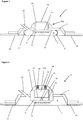
- FIG. 1 there is depicted schematically a device 1, which can be employed to remove fluid from a body, according to a preferred embodiment of the first aspect of the invention.
- the device 1 is shown positioned on a skin surface 3 of a human body (not shown).
- the device 1 incorporates an array of microneedles 5 positioned substantially parallel to the skin surface 3 within a housing 7, the housing 7 defining a chamber 9.
- Each needle 11 in the array 5 is around 550 ⁇ m in height.
- the housing 7 defines a port 13 configured for connection to a vacuum device (not shown) such that negative pressure can be applied to the chamber 9.
- An adhesive (not shown) is provided on a skin contacting surface 15 of the housing 7 to allow the housing 7 to be hermetically sealed to the skin surface 3.
- the device 1 further incorporates two resilient living hinges 17 positioned between a lower surface 19 of the housing 7 and the skin surface 3.
- An operating member, or button, 21 is connected to a rear surface 23 of the microneedle array 5, and extends backwards therefrom, such that an upper portion 21A of the button 21 lies above the housing 7.
- a diaphragm 25 is positioned over the upper portion of the button 21 and is connected to the housing 7 either side of the button 21.
- the skin surface 3 to which the device 1 will be applied is wiped with a bacteriocidal solution and the device 1 positioned against the skin surface 3.
- a vacuum device (not shown) is attached to the port 13 by means of tubing (not shown).
- a downward force (which could be applied by the patient themselves, a medical practitioner, or a dedicated microneedle applicator device) is exerted upon the button 21 which results in the movement of the microneedle array 5 downwards from the disengaged position (as shown in Figure 1 ) to the engaged position, where the microneedles 11 penetrate the skin 3.
- the device 1 of Figure 1 is made of a semi-flexible material such that on depression of the button 21 the entire body of the housing 7 flexes towards the surface of the skin 3 such that the microneedles 11 penetrate the skin surface 3.
- the downwards force exerted on the button 21 results in the living hinges 17 flexing outwardly.
- the resilience of the living hinges 17 causes them to expand back to their original conformation, lifting the microneedle array 5 off the skin surface 3 and returning the microneedle array 5 to the disengaged position as shown in Figure 1 .
- the vacuum device is activated, such that a negative pressure is applied to the chamber 9.
- the living hinges 17 have sufficient inherent resilience that upon application of a sufficient negative pressure to the chamber 9 to drive fluid flow from the body (described in more detail below), the microneedle array 5 does not drop down to the engaged position against the skin surface 3 despite the inherent flexibility of the housing 7.
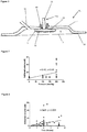
- FIG. 2 there is depicted schematically a device 31, which can be employed to remove interstitial fluid from a body, according to another preferred embodiment of the first aspect of the invention.
- the device 31 is shown positioned on a skin surface 3 of a human body (not shown). Similar to the device 1 shown in Figure 1 , the device 31 incorporates an array of microneedles 5 positioned substantially parallel to the skin surface 3 within a housing 7, the housing 7 defining a chamber 9. Each needle 11 in the array is around 550 ⁇ m in height.
- the housing 7 defines a port 13 configured for connection to a vacuum device (not shown) such that negative pressure can be applied to the chamber 9.
- An adhesive (not shown) is provided on a skin contacting surface 15 of the housing 7 to allow the housing 7 to be hermetically sealed to the skin surface 3.
- An operating member, or button, 21 is positioned above the microneedle array 5 and extends vertically, such that an upper portion 21A of the button 21 is located above the housing 7.
- the button 21 is connectable to the rear of the microneedle array 23 by way of connectors 33, 35 positioned on an upper surface 23 of the microneedle array 9 and a lower surface 37 of the button 21 respectfully.
- Positioned between the top 21B of the button 21 and a diaphragm 25 are springs 39.
- the diaphragm 25 is positioned over the top 21B of the button 21 and the springs 39 and is connected to the housing 7 either side of the button 21.
- the device 31 When in use, the device 31 is positioned on the skin surface 3 through which fluid is to be extracted.
- a vacuum device (not shown) is attached to the port 13 by means of tubing (not shown).
- a downward force (which could be applied by the patient themselves, a medical practitioner, or a dedicated microneedle applicator device) is exerted upon the button 21 which moves the button 21 through the housing 7 towards the microneedle array 5. This movement results in connection of the button 21 with the microneedle array 5 via connectors 33, 35.
- the microneedle array 5 moves downwards from the disengaged position (as shown in Figure 2 ) to an engaged position, where the microneedles 11 penetrate the skin surface 3.
- the device 31 of Figure 2 is made of a rigid material such that when the downward force is exerted on the button 21, the button 21 moves downwards through the housing 7 before contacting the microneedle array 5, which it then drives towards the skin surface 3.
- the downwards force exerted on the button 21 results in the springs 39 being stretched.
- the springs 39 return to their original conformation. This results in the button 21 returning to its original position, and the microneedle array 5 returning to the disengaged position (as shown in Figure 2 ) by virtue of its connection to the button 21 via the connectors 33, 35.
- the vacuum device is activated, such that a negative pressure is applied to the chamber 9.
- the springs 39 have sufficient inherent resilience that, upon application of the negative pressure to the chamber 9, the microneedle array 5 does not return to the engaged position where the microneedles 7 penetrate the skin surface 3.
- interstitial fluid is extracted from the body via holes in the skin made by the microneedles 11 penetrating the skin surface 3.
- the interstitial fluid is passed via the port 13 and vacuum tubing (not shown) to a storage canister (not shown).
- the vacuum can be deactivated and the device 31 removed from the surface of the skin 3.
- the entire device 31 may be disposed of, or alternatively, the connectors 33, 35 may be disengaged and the microneedle array 5 removed from the device 31, and replaced by a new microneedle array 5 for future use.
- FIG. 3 there is depicted schematically a device 41, which can be employed to remove interstitial fluid from a body, according to another preferred embodiment of the first aspect of the invention.
- the device 41 is shown positioned on a skin surface 3 of a human body (not shown). Similar to the device 1 shown in Figure 1 , the device 41 incorporates an array of microneedles 5 positioned substantially parallel to the skin surface 3 within a housing 7, the housing 7 defining a chamber 9. Each needle 11 in the array is around 550 ⁇ m in height.
- the housing 7 defines a port 13 configured for connection to a vacuum device (not shown) such that negative pressure can be applied to the chamber 9.
- An adhesive (not shown) is provided on a skin contacting surface 15 of the housing 7 to allow the housing 7 to be hermetically sealed to the skin surface 3.
- An operating member 21 is connected to a rear surface 23 of the microneedle array 5, and extends backwards therefrom, such that an upper portion 21A of the operating member 21 lies above the housing 7.
- a diaphragm 43 connects the operating member (in this case the upper portion 21A of the operating member 21) to the housing 7. The diaphragm 43 is positioned to seal the boundary between the housing 7 and operating member 21 so as to prevent leakage through the boundary when the vacuum is engaged.
- the skin surface 3 to which the device 41 will be applied is wiped with a bacteriocidal solution and the device 41 positioned against the skin surface 3.
- a vacuum device (not shown) is attached to the port 13 by means of tubing (not shown).
- a downward force (which could be applied by the patient themselves, a medical practitioner, or a dedicated microneedle applicator device) is exerted upon the operating member 21 which results in the movement of the microneedle array 5 downwards from the disengaged position (as shown in Figure 3 ) to the engaged position, where the microneedles 11 penetrate the skin 3.
- the diaphragm 43 of Figure 3 is made of a flexible resilient material such that on depression of the operating member 21 the diaphragm 43 flexes, allowing the operating member 21 to move towards the surface of the skin 3. On removal of the downwards force from the operating member 21, the resilience of the diaphragm 43 causes the operating member 21 to move back to its original position, lifting the microneedle array 5 off the skin surface 3 and returning the microneedle array 5 to the disengaged position as shown in Figure 3 .
- the vacuum device is activated such that a negative pressure is applied to the chamber 9.
- the operating member 21 has a sufficiently small diameter such that, combined with the resilience of the diaphragm 43, upon application of a sufficient negative pressure to the chamber 9 to drive fluid flow from the body (described in more detail below), the microneedle array 5 does not drop down to the engaged position against the skin surface 3.
- FIG. 4A and 4B there is depicted schematically an applicator device 51 according to a preferred embodiment of the applicator of the invention which can be used to apply microneedles to a surface.
- the device 51 is shown positioned above a skin surface 3 of a human body (not shown) onto which a microneedle array 53 has been placed.
- the device 51 incorporates a hammer 55, a base plate 57, a pressure element 59 and a latch 61 located within a housing 63.
- the hammer 55 is attached to the base plate 57. On release of the latch 61, the hammer 55 can move between a primed position (shown in Figure 4A ) and an impact position (shown in Figure 4B ) where it impacts the pressure element 59.
- the hammer 55 comprises an elongate shaft 65 and an impact member 67 located towards the end of the shaft 65 furthest from the base plate 57.
- An operating handle 69 and a notch 73 for engagement with the latch 61 also form part of the hammer 55.
- the hammer 55 is pivotally connected to the base plate 57 via the opposite end of the shaft to that which the impact member 67 in connected.
- the hammer 55 further comprises a spring 75 which biases the hammer 55 towards the impact position (shown in Figure 4B ).
- a user retracts the hammer 55 away from the base plate in the direction of arrow X.
- the latch 61 engages with the notch 73, retaining the hammer 55 in the primed position.
- the base plate 57 defines an opening 71 through which the pressure element 59 can project (or within which the pressure element 59 can reside) to engage the underlying microneedle array 53.
- the pressure element 59 engages with engagement button 77 on the rear of the microneedle array 53.
- the latch element 61 pivots anticlockwise to release the latch element 61 from the notch 73 and thereby release the hammer 55, and the spring 75 drives the hammer 55 from the primed position to the impact position.
- the pressure element could engage with any suitable element or surface associated with the microneedle array, for example a housing in which the microneedle array is disposed or directly contact the rear of the microneedle array.
- the impact member 67 of the hammer 55 exerts a force on the rear of the pressure element 59 which force is subsequently transferred to the engagement button 77 and microneedle array 53, thereby applying the microneedles (not shown) to the skin surface 3.
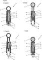
- an applicator device 81 according to a preferred embodiment of the applicator of the invention which can be used to apply microneedles to a surface.
- the device 81 is shown in four configurations: A: Supplied; B: Primed; C: Triggered; and D: Impact.
- the device 81 comprises an elongate tubular housing 83 containing a hammer 85, a latch 87 and a pressure element 89.
- the hammer 85 is moveable within the housing 83 from a primed position (shown in Figure 5B ) to an impact position (shown in Figure 5D ) where the hammer 85 impacts the pressure element 89 (described more fully below).
- the hammer 85 is concentrically disposed within the housing 83 and comprises an elongate shaft 91, an impact member 93 located at one end of the shaft 91, an operating handle 95 located at the opposite end of the shaft 91 and a notch 97 for engagement with the latch 87.
- the hammer 85 further comprises a spring 99 which biases the hammer 85 towards the impact position in which the impact member 93 is in contact with the pressure element 89 (shown in Figure 5D ).
- the hammer 85 is moveable axially relative to the housing 83 away from the pressure element 89 towards a primed position (shown in Figure 5B ).
- a primed position shown in Figure 5B .
- the latch 87 engages with the notch 97 to retain the hammer 85 in the primed position against the biasing force of the spring 99. Disengagement of the latch 87 releases the hammer 85 which is driven by the spring 99 to the impact position.
- the latch 87 is pivotally attached to the housing 83 and defines an inwardly projecting knob 101 which projects into the housing 83.
- the latch 87 pivots anticlockwise and engages the notch 97, thereby maintaining the hammer 85 in the primed position.
- the latch 87 is biased towards engagement with the notch 97 by means of a spring 103.
- the pivoting of the latch 87 also results in the knob 101 contacting the pressure element 89 and moving the pressure element 89 downwards relative to the housing 83 into a primed position (described in more detail below).
- the pressure element 89 comprises a dome-shaped contact portion 105 for contacting the rear of a microneedle array (not shown) and an elongate portion 107 extending within the housing 83 whose upper end contacts the knob 101 of the latch 87.
- the dome-shaped contact portion 105 projects out of the housing 83 at the end which is proximate the impact member 93 when the hammer 85 is in the engaged position.
- the pressure element 89 can move axially relative to the housing 83 between an inactive position (shown in Figure 5A ) and a primed position (shown in Figure 5B ). This movement between inactive and primed positions results from movement of the hammer 85 upwards relative to the housing 83 to the primed position, which allows the latch 87 to pivot anticlockwise and the knob 101 to force down the elongate portion 107.
- the dome-shaped contact portion 105 of the pressure element 89 is configured to engage with the rear of a microneedle array (not shown).
- the elongate portion 107 moves axially upwards relative to the housing 83 which pivots the latch 87 via contact of the elongate position 107 of the pressure element 89 with the knob 101.
- the impact member 93 of the hammer 85 exerts a force on the rear of the pressure element 89 which force is subsequently transferred to the rear of the microneedle array, thereby applying the microneedles to the skin.
- the hammer 85 When in use, the hammer 85 is moved to the primed position through exertion of a force being applied to the operating handle 95. Said force could, for example, be applied by the patient or a medical practitioner. Exertion of said force and subsequent movement of the hammer 85 results in the latch 87 engaging with the notch 97 which maintains the hammer 85 in the primed position without continued application of said force.
- the device 81 is then positioned in the region of a microneedle array (not shown) applied to the skin surface of a body (not shown).
- the pressure element 89 is applied to the rear of the microneedle array, which results in the latch 87 pivoting and releasing the hammer 85 from the primed position.
- the spring 99 drives the hammer 85 towards the engaged position where the impact member 93 exerts a force on the rear of the pressure element 89 which force is transferred to the microneedle array, thereby applying the microneedles to the skin.
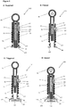
- FIG. 6A-D there is depicted schematically an applicator device 121 according to a preferred embodiment of the applicator of the invention which can be used to apply microneedles to a surface.
- the device 121 is shown in four configurations: A: Supplied; B: Primed; C: Triggered; and D: Impact.
- This embodiment of the applicator of the invention is similar to the embodiment shown in figures 5A-D and so the same reference numbers shall be used in figures 6A-D as are used above in relation to the same features in the embodiment shown in figures 5A-D .
- the device 121 comprises an elongate tubular housing 83 containing a hammer 85, a latch 87 and a pressure element 89.
- the hammer 85 is moveable within the housing 83 from a primed position (shown in Figure 6B ) to an impact position (shown in Figure 6D ) where the hammer 85 impacts a microneedle array 108 (described more fully below).
- the hammer 85 is concentrically disposed within the housing 83 and comprises an elongate shaft 91, an impact member 93 located at one end of the shaft 91, an operating handle 95 located at the opposite end of the shaft 91 and a notch 97 for engagement with the latch 87.
- the hammer 85 further comprises a spring 99 which biases the hammer 85 towards the impact position in which the impact member 93 is in contact with the microneedle array 108, in use (shown in Figure 6D ).
- the hammer 85 is moveable axially relative to the housing 83 away from the pressure element 89 towards a primed position (shown in Figure 6B ).
- a primed position shown in Figure 6B .
- the latch 87 engages with the notch 97 to retain the hammer 85 in the primed position against the biasing force of the spring 99. Disengagement of the latch 87 releases the hammer 85 which is driven by the spring 99 to the impact position.
- the latch 87 is pivotally attached to the housing 83 and defines an inwardly projecting knob 101 which projects into the housing 83.
- the latch 87 pivots anticlockwise and engages the notch 97, thereby maintaining the hammer 85 in the primed position.
- the latch 87 is biased towards engagement with the notch 97 by means of a spring 103.
- the pivoting of the latch 87 also results in the knob 101 contacting the pressure element 89 and moving the pressure element 89 downwards relative to the housing 83 into a primed position (described in more detail below).
- the pressure element 89 comprises a contact portion 105 for contacting the rear of a housing 109 for a microneedle array 108, and an elongate portion 107 extending within the housing 83 whose upper end contacts the knob 101 of the latch 87.
- the contact portion 105 projects out of the housing 83 at the end which is proximate the impact member 93 when the hammer 85 is in the engaged position.
- the pressure element 89 can move axially relative to the housing 83 between an inactive position (shown in Figure 6A ) and a primed position (shown in Figure 6B ). This movement between inactive and primed positions results from movement of the hammer 85 upwards relative to the housing 83 to the primed position, which allows the latch 87 to pivot anticlockwise and the knob 101 to force down the elongate portion 107.
- the contact portion 105 of the pressure element 89 is configured to engage with the rear of a housing 109 for the microneedle array 108.
- the elongate portion 107 moves axially upwards relative to the housing 83 which pivots the latch 87 via contact of the elongate position 107 of the pressure element 89 with the knob 101.
- the impact member 93 of the hammer 85 exerts a force on the rear of the microneedle array 108 which force applies the microneedles to the skin 110.
- the hammer 85 When in use, the hammer 85 is moved to the primed position through exertion of a force being applied to the operating handle 95. Said force could, for example, be applied by the patient or a medical practitioner. Exertion of said force and subsequent movement of the hammer 85 results in the latch 87 engaging with the notch 97 which maintains the hammer 85 in the primed position without continued application of said force.
- the device 81 is then positioned in the region of a microneedle array 108 positioned within a housing 109 applied to the skin surface of a body 110.
- the pressure element 89 is applied to the housing 109 for the microneedles 108, which results in the latch 87 pivoting and releasing the hammer 85 from the primed position.
- the spring 99 drives the hammer 85 towards the engaged position where the impact member 93 exerts a force on the rear of the microneedle array 108 which force applies the microneedles to the skin 110.
Landscapes
- Health & Medical Sciences (AREA)
- Life Sciences & Earth Sciences (AREA)
- Heart & Thoracic Surgery (AREA)
- Hematology (AREA)
- Veterinary Medicine (AREA)
- Public Health (AREA)
- Engineering & Computer Science (AREA)
- Biomedical Technology (AREA)
- General Health & Medical Sciences (AREA)
- Animal Behavior & Ethology (AREA)
- Surgery (AREA)
- Pathology (AREA)
- Molecular Biology (AREA)
- Medical Informatics (AREA)
- Biophysics (AREA)
- Physics & Mathematics (AREA)
- Vascular Medicine (AREA)
- Anesthesiology (AREA)
- Dermatology (AREA)
- Pain & Pain Management (AREA)
- Media Introduction/Drainage Providing Device (AREA)
- External Artificial Organs (AREA)
Applications Claiming Priority (2)
| Application Number | Priority Date | Filing Date | Title |
|---|---|---|---|
| GBGB1401133.2A GB201401133D0 (en) | 2014-01-23 | 2014-01-23 | Fluid extraction device, applicator device and associated methods |
| PCT/GB2015/050164 WO2015110833A1 (en) | 2014-01-23 | 2015-01-23 | Fluid extraction device, applicator device and associated methods |
Publications (2)
| Publication Number | Publication Date |
|---|---|
| EP3096687A1 EP3096687A1 (en) | 2016-11-30 |
| EP3096687B1 true EP3096687B1 (en) | 2021-06-09 |
Family
ID=50287444
Family Applications (1)
| Application Number | Title | Priority Date | Filing Date |
|---|---|---|---|
| EP15701415.0A Active EP3096687B1 (en) | 2014-01-23 | 2015-01-23 | Fluid extraction device, applicator device and associated methods |
Country Status (5)
| Country | Link |
|---|---|
| US (2) | US10441691B2 (enExample) |
| EP (1) | EP3096687B1 (enExample) |
| JP (1) | JP6537531B2 (enExample) |
| GB (1) | GB201401133D0 (enExample) |
| WO (1) | WO2015110833A1 (enExample) |
Families Citing this family (23)
| Publication number | Priority date | Publication date | Assignee | Title |
|---|---|---|---|---|
| ES2912965T3 (es) | 2015-09-09 | 2022-05-30 | Drawbridge Health Inc | Dispositivos para la recopilación, estabilización y conservación de muestras |
| CN105266852B (zh) * | 2015-11-24 | 2017-12-01 | 贾爱娟 | 一种医疗检验用装置 |
| EP3395397B1 (en) * | 2015-12-21 | 2022-10-12 | Medrx Co., Ltd. | Microneedle patch applicator housing |
| CN210383905U (zh) | 2017-01-10 | 2020-04-24 | 集联健康有限公司 | 一种用于从受试者收集流体样品的装置以及运输套筒 |
| WO2019126735A1 (en) | 2017-12-21 | 2019-06-27 | Georgia Tech Research Corporation | Methods and systems for improved collection of interstitial fluid |
| JPWO2019188907A1 (ja) * | 2018-03-29 | 2021-04-08 | 富士フイルム株式会社 | 採血用ランセット及び血液検査キット |
| JP2021101749A (ja) * | 2018-03-29 | 2021-07-15 | テルモ株式会社 | 医療器具 |
| US20210353267A1 (en) * | 2018-10-19 | 2021-11-18 | Kenota Inc. | Interstitial fluid extraction |
| WO2020146045A1 (en) * | 2019-01-11 | 2020-07-16 | University Of Cincinnati | Continuous extraction and sensing of interstitial fluid |
| DE102019200557A1 (de) * | 2019-01-17 | 2020-07-23 | Lts Lohmann Therapie-Systeme Ag | Applikator |
| JP7074714B2 (ja) * | 2019-04-17 | 2022-05-24 | 富士フイルム株式会社 | 収容容器、マイクロニードルユニット、収容容器群、及びマイクロニードルユニットの製造方法 |
| US20210153848A1 (en) * | 2019-11-21 | 2021-05-27 | Imcomet B.V. | Skin cancer treatment |
| US12053284B2 (en) * | 2021-11-08 | 2024-08-06 | Satio, Inc. | Dermal patch for collecting a physiological sample |
| US11510602B1 (en) * | 2021-11-08 | 2022-11-29 | Satio, Inc. | Dermal patch for collecting a physiological sample |
| US12023156B2 (en) | 2021-10-13 | 2024-07-02 | Satio, Inc. | Dermal patch for collecting a physiological sample |
| US11877848B2 (en) * | 2021-11-08 | 2024-01-23 | Satio, Inc. | Dermal patch for collecting a physiological sample |
| US12214346B2 (en) | 2021-10-13 | 2025-02-04 | Satio, Inc. | Dermal patch with a diagnostic test strip |
| US11964121B2 (en) | 2021-10-13 | 2024-04-23 | Satio, Inc. | Mono dose dermal patch for pharmaceutical delivery |
| US12178979B2 (en) | 2021-10-13 | 2024-12-31 | Satio, Inc. | Dermal patch for delivering a pharmaceutical |
| US12048543B2 (en) * | 2021-11-08 | 2024-07-30 | Satio, Inc. | Dermal patch for collecting a physiological sample with removable vial |
| US11452474B1 (en) | 2021-04-14 | 2022-09-27 | Satio, Inc. | Dual lever dermal patch system |
| SE546125C2 (en) * | 2022-10-13 | 2024-05-28 | Ascilion Ab | A device for sampling a bodily fluid from a test subject |
| CN115644867A (zh) * | 2022-12-02 | 2023-01-31 | 苏州纳通生物纳米技术有限公司 | 采样装置、采样仪和采样方法 |
Family Cites Families (12)
| Publication number | Priority date | Publication date | Assignee | Title |
|---|---|---|---|---|
| ES2239053T3 (es) * | 1999-12-16 | 2005-09-16 | Alza Corporation | Dispositivo para incrementar el flujo transdermico de sustancias de muestreo. |
| AT409253B (de) | 2000-07-20 | 2002-07-25 | Innova Patent Gmbh | Anlage zur beförderung von personen und verfahren zum betrieb einer derartigen anlage |
| ATE485331T1 (de) | 2003-01-06 | 2010-11-15 | Nektar Therapeutics | Thiolselektive wasserlösliche polymerderivate |
| WO2005044333A2 (en) | 2003-10-31 | 2005-05-19 | Alza Corporation | Self-actuating applicator for microprojection array |
| WO2005123173A1 (en) * | 2004-06-10 | 2005-12-29 | 3M Innovative Properties Company | Patch application device and kit |
| GB0802447D0 (en) | 2008-02-09 | 2008-03-19 | Univ Manchester | Fluid extraction device, associated materials and methods |
| US9295417B2 (en) | 2011-04-29 | 2016-03-29 | Seventh Sense Biosystems, Inc. | Systems and methods for collecting fluid from a subject |
| US10010706B2 (en) * | 2009-07-31 | 2018-07-03 | 3M Innovative Properties Company | Hollow microneedle arrays |
| US20110172645A1 (en) * | 2010-01-08 | 2011-07-14 | Ratio, Inc. | Wearable drug delivery device including integrated pumping and activation elements |
| SG184128A1 (en) | 2010-03-17 | 2012-10-30 | Nanomed Devices Inc | A built-in non-verbal instructional device integratable to applicators |
| ES2565805T3 (es) | 2010-11-09 | 2016-04-07 | Seventh Sense Biosystems, Inc. | Sistemas e interfaces para el muestreo de sangre |
| KR102237667B1 (ko) * | 2011-04-29 | 2021-04-12 | 세븐쓰 센스 바이오시스템즈, 인크. | 유체들의 전달 및/또는 수용 |
-
2014
- 2014-01-23 GB GBGB1401133.2A patent/GB201401133D0/en not_active Ceased
-
2015
- 2015-01-23 WO PCT/GB2015/050164 patent/WO2015110833A1/en not_active Ceased
- 2015-01-23 JP JP2016565577A patent/JP6537531B2/ja not_active Expired - Fee Related
- 2015-01-23 EP EP15701415.0A patent/EP3096687B1/en active Active
- 2015-01-23 US US15/113,249 patent/US10441691B2/en not_active Expired - Fee Related
-
2019
- 2019-09-30 US US16/587,857 patent/US20200101205A1/en not_active Abandoned
Non-Patent Citations (1)
| Title |
|---|
| None * |
Also Published As
| Publication number | Publication date |
|---|---|
| US10441691B2 (en) | 2019-10-15 |
| GB201401133D0 (en) | 2014-03-12 |
| EP3096687A1 (en) | 2016-11-30 |
| WO2015110833A1 (en) | 2015-07-30 |
| US20200101205A1 (en) | 2020-04-02 |
| JP6537531B2 (ja) | 2019-07-03 |
| US20170021067A1 (en) | 2017-01-26 |
| JP2017509449A (ja) | 2017-04-06 |
Similar Documents
| Publication | Publication Date | Title |
|---|---|---|
| EP3096687B1 (en) | Fluid extraction device, applicator device and associated methods | |
| JP6776245B2 (ja) | 経皮的脈管傷害治療システムおよび方法 | |
| JP6224745B2 (ja) | 可撓性および共形性を有するパッチポンプ | |
| ES2802236T3 (es) | Conjunto de infusión automática en ángulo | |
| CN205019519U (zh) | 用于药物输注的倾斜插入器 | |
| JP3136041U (ja) | 止血器具 | |
| JP2005521527A (ja) | 物質を皮内に供給する方法およびデバイス | |
| US20100130958A1 (en) | Device and Methods for Subcutaneous Delivery of High Viscosity Fluids | |
| JP2008528086A (ja) | 保護された穿刺装置を有する医療用装置 | |
| WO2008082528B1 (en) | Chronic access system for extracorporeal treatment of blood including a continuously wearable hemodialyzer | |
| EP3003459A1 (en) | Microneedle injection apparatus comprising an inverted actuator | |
| JP2009101217A (ja) | 経皮投与手段 | |
| US20110202014A1 (en) | Adapter device for application of small amounts of fat graft material by use of syringes | |
| RR Singh et al. | Review of patents on microneedle applicators | |
| KR20080046605A (ko) | 여드름을 치료하기 위한 피부 피어싱 장치 | |
| CN112791267B (zh) | 一种输液港 | |
| CA3202866A1 (en) | Wound dressing | |
| US20250120852A1 (en) | Devices for bleeding reduction and methods of making and using the same | |
| RU2850704C1 (ru) | Имплантируемый инфузионный порт | |
| US20120101471A1 (en) | Self-powered infusion device and method of use | |
| AU2025220798A1 (en) | Injection assembly for a wearable auto-injector, and wearable auto-injector | |
| CN113423446A (zh) | 皮下给药用留置针 | |
| RU2021102032A (ru) | Медицинское устройство для чрескожной вставки канюли в ткань тела |
Legal Events
| Date | Code | Title | Description |
|---|---|---|---|
| PUAI | Public reference made under article 153(3) epc to a published international application that has entered the european phase |
Free format text: ORIGINAL CODE: 0009012 |
|
| 17P | Request for examination filed |
Effective date: 20160726 |
|
| AK | Designated contracting states |
Kind code of ref document: A1 Designated state(s): AL AT BE BG CH CY CZ DE DK EE ES FI FR GB GR HR HU IE IS IT LI LT LU LV MC MK MT NL NO PL PT RO RS SE SI SK SM TR |
|
| AX | Request for extension of the european patent |
Extension state: BA ME |
|
| RIN1 | Information on inventor provided before grant (corrected) |
Inventor name: MIDDLETON, IAN Inventor name: TODD, SIMON |
|
| DAX | Request for extension of the european patent (deleted) | ||
| STAA | Information on the status of an ep patent application or granted ep patent |
Free format text: STATUS: EXAMINATION IS IN PROGRESS |
|
| 17Q | First examination report despatched |
Effective date: 20190214 |
|
| GRAP | Despatch of communication of intention to grant a patent |
Free format text: ORIGINAL CODE: EPIDOSNIGR1 |
|
| STAA | Information on the status of an ep patent application or granted ep patent |
Free format text: STATUS: GRANT OF PATENT IS INTENDED |
|
| INTG | Intention to grant announced |
Effective date: 20200915 |
|
| GRAS | Grant fee paid |
Free format text: ORIGINAL CODE: EPIDOSNIGR3 |
|
| GRAA | (expected) grant |
Free format text: ORIGINAL CODE: 0009210 |
|
| STAA | Information on the status of an ep patent application or granted ep patent |
Free format text: STATUS: THE PATENT HAS BEEN GRANTED |
|
| AK | Designated contracting states |
Kind code of ref document: B1 Designated state(s): AL AT BE BG CH CY CZ DE DK EE ES FI FR GB GR HR HU IE IS IT LI LT LU LV MC MK MT NL NO PL PT RO RS SE SI SK SM TR |
|
| REG | Reference to a national code |
Ref country code: GB Ref legal event code: FG4D |
|
| REG | Reference to a national code |
Ref country code: CH Ref legal event code: EP Ref country code: AT Ref legal event code: REF Ref document number: 1399820 Country of ref document: AT Kind code of ref document: T Effective date: 20210615 |
|
| REG | Reference to a national code |
Ref country code: DE Ref legal event code: R096 Ref document number: 602015070198 Country of ref document: DE |
|
| REG | Reference to a national code |
Ref country code: IE Ref legal event code: FG4D |
|
| REG | Reference to a national code |
Ref country code: LT Ref legal event code: MG9D |
|
| PG25 | Lapsed in a contracting state [announced via postgrant information from national office to epo] |
Ref country code: HR Free format text: LAPSE BECAUSE OF FAILURE TO SUBMIT A TRANSLATION OF THE DESCRIPTION OR TO PAY THE FEE WITHIN THE PRESCRIBED TIME-LIMIT Effective date: 20210609 Ref country code: BG Free format text: LAPSE BECAUSE OF FAILURE TO SUBMIT A TRANSLATION OF THE DESCRIPTION OR TO PAY THE FEE WITHIN THE PRESCRIBED TIME-LIMIT Effective date: 20210909 Ref country code: LT Free format text: LAPSE BECAUSE OF FAILURE TO SUBMIT A TRANSLATION OF THE DESCRIPTION OR TO PAY THE FEE WITHIN THE PRESCRIBED TIME-LIMIT Effective date: 20210609 Ref country code: FI Free format text: LAPSE BECAUSE OF FAILURE TO SUBMIT A TRANSLATION OF THE DESCRIPTION OR TO PAY THE FEE WITHIN THE PRESCRIBED TIME-LIMIT Effective date: 20210609 |
|
| REG | Reference to a national code |
Ref country code: AT Ref legal event code: MK05 Ref document number: 1399820 Country of ref document: AT Kind code of ref document: T Effective date: 20210609 |
|
| REG | Reference to a national code |
Ref country code: NL Ref legal event code: MP Effective date: 20210609 |
|
| PG25 | Lapsed in a contracting state [announced via postgrant information from national office to epo] |
Ref country code: LV Free format text: LAPSE BECAUSE OF FAILURE TO SUBMIT A TRANSLATION OF THE DESCRIPTION OR TO PAY THE FEE WITHIN THE PRESCRIBED TIME-LIMIT Effective date: 20210609 Ref country code: GR Free format text: LAPSE BECAUSE OF FAILURE TO SUBMIT A TRANSLATION OF THE DESCRIPTION OR TO PAY THE FEE WITHIN THE PRESCRIBED TIME-LIMIT Effective date: 20210910 Ref country code: RS Free format text: LAPSE BECAUSE OF FAILURE TO SUBMIT A TRANSLATION OF THE DESCRIPTION OR TO PAY THE FEE WITHIN THE PRESCRIBED TIME-LIMIT Effective date: 20210609 Ref country code: SE Free format text: LAPSE BECAUSE OF FAILURE TO SUBMIT A TRANSLATION OF THE DESCRIPTION OR TO PAY THE FEE WITHIN THE PRESCRIBED TIME-LIMIT Effective date: 20210609 Ref country code: NO Free format text: LAPSE BECAUSE OF FAILURE TO SUBMIT A TRANSLATION OF THE DESCRIPTION OR TO PAY THE FEE WITHIN THE PRESCRIBED TIME-LIMIT Effective date: 20210909 |
|
| PG25 | Lapsed in a contracting state [announced via postgrant information from national office to epo] |
Ref country code: EE Free format text: LAPSE BECAUSE OF FAILURE TO SUBMIT A TRANSLATION OF THE DESCRIPTION OR TO PAY THE FEE WITHIN THE PRESCRIBED TIME-LIMIT Effective date: 20210609 Ref country code: CZ Free format text: LAPSE BECAUSE OF FAILURE TO SUBMIT A TRANSLATION OF THE DESCRIPTION OR TO PAY THE FEE WITHIN THE PRESCRIBED TIME-LIMIT Effective date: 20210609 Ref country code: SK Free format text: LAPSE BECAUSE OF FAILURE TO SUBMIT A TRANSLATION OF THE DESCRIPTION OR TO PAY THE FEE WITHIN THE PRESCRIBED TIME-LIMIT Effective date: 20210609 Ref country code: SM Free format text: LAPSE BECAUSE OF FAILURE TO SUBMIT A TRANSLATION OF THE DESCRIPTION OR TO PAY THE FEE WITHIN THE PRESCRIBED TIME-LIMIT Effective date: 20210609 Ref country code: NL Free format text: LAPSE BECAUSE OF FAILURE TO SUBMIT A TRANSLATION OF THE DESCRIPTION OR TO PAY THE FEE WITHIN THE PRESCRIBED TIME-LIMIT Effective date: 20210609 Ref country code: PT Free format text: LAPSE BECAUSE OF FAILURE TO SUBMIT A TRANSLATION OF THE DESCRIPTION OR TO PAY THE FEE WITHIN THE PRESCRIBED TIME-LIMIT Effective date: 20211011 Ref country code: RO Free format text: LAPSE BECAUSE OF FAILURE TO SUBMIT A TRANSLATION OF THE DESCRIPTION OR TO PAY THE FEE WITHIN THE PRESCRIBED TIME-LIMIT Effective date: 20210609 Ref country code: ES Free format text: LAPSE BECAUSE OF FAILURE TO SUBMIT A TRANSLATION OF THE DESCRIPTION OR TO PAY THE FEE WITHIN THE PRESCRIBED TIME-LIMIT Effective date: 20210609 Ref country code: AT Free format text: LAPSE BECAUSE OF FAILURE TO SUBMIT A TRANSLATION OF THE DESCRIPTION OR TO PAY THE FEE WITHIN THE PRESCRIBED TIME-LIMIT Effective date: 20210609 |
|
| PG25 | Lapsed in a contracting state [announced via postgrant information from national office to epo] |
Ref country code: PL Free format text: LAPSE BECAUSE OF FAILURE TO SUBMIT A TRANSLATION OF THE DESCRIPTION OR TO PAY THE FEE WITHIN THE PRESCRIBED TIME-LIMIT Effective date: 20210609 |
|
| REG | Reference to a national code |
Ref country code: DE Ref legal event code: R097 Ref document number: 602015070198 Country of ref document: DE |
|
| PLBE | No opposition filed within time limit |
Free format text: ORIGINAL CODE: 0009261 |
|
| STAA | Information on the status of an ep patent application or granted ep patent |
Free format text: STATUS: NO OPPOSITION FILED WITHIN TIME LIMIT |
|
| PG25 | Lapsed in a contracting state [announced via postgrant information from national office to epo] |
Ref country code: DK Free format text: LAPSE BECAUSE OF FAILURE TO SUBMIT A TRANSLATION OF THE DESCRIPTION OR TO PAY THE FEE WITHIN THE PRESCRIBED TIME-LIMIT Effective date: 20210609 |
|
| 26N | No opposition filed |
Effective date: 20220310 |
|
| PG25 | Lapsed in a contracting state [announced via postgrant information from national office to epo] |
Ref country code: AL Free format text: LAPSE BECAUSE OF FAILURE TO SUBMIT A TRANSLATION OF THE DESCRIPTION OR TO PAY THE FEE WITHIN THE PRESCRIBED TIME-LIMIT Effective date: 20210609 |
|
| PG25 | Lapsed in a contracting state [announced via postgrant information from national office to epo] |
Ref country code: IT Free format text: LAPSE BECAUSE OF FAILURE TO SUBMIT A TRANSLATION OF THE DESCRIPTION OR TO PAY THE FEE WITHIN THE PRESCRIBED TIME-LIMIT Effective date: 20210609 |
|
| REG | Reference to a national code |
Ref country code: DE Ref legal event code: R119 Ref document number: 602015070198 Country of ref document: DE |
|
| PG25 | Lapsed in a contracting state [announced via postgrant information from national office to epo] |
Ref country code: MC Free format text: LAPSE BECAUSE OF FAILURE TO SUBMIT A TRANSLATION OF THE DESCRIPTION OR TO PAY THE FEE WITHIN THE PRESCRIBED TIME-LIMIT Effective date: 20210609 |
|
| REG | Reference to a national code |
Ref country code: CH Ref legal event code: PL |
|
| GBPC | Gb: european patent ceased through non-payment of renewal fee |
Effective date: 20220123 |
|
| REG | Reference to a national code |
Ref country code: BE Ref legal event code: MM Effective date: 20220131 |
|
| PG25 | Lapsed in a contracting state [announced via postgrant information from national office to epo] |
Ref country code: LU Free format text: LAPSE BECAUSE OF NON-PAYMENT OF DUE FEES Effective date: 20220123 Ref country code: GB Free format text: LAPSE BECAUSE OF NON-PAYMENT OF DUE FEES Effective date: 20220123 Ref country code: DE Free format text: LAPSE BECAUSE OF NON-PAYMENT OF DUE FEES Effective date: 20220802 |
|
| PG25 | Lapsed in a contracting state [announced via postgrant information from national office to epo] |
Ref country code: FR Free format text: LAPSE BECAUSE OF NON-PAYMENT OF DUE FEES Effective date: 20220131 Ref country code: BE Free format text: LAPSE BECAUSE OF NON-PAYMENT OF DUE FEES Effective date: 20220131 |
|
| PG25 | Lapsed in a contracting state [announced via postgrant information from national office to epo] |
Ref country code: LI Free format text: LAPSE BECAUSE OF NON-PAYMENT OF DUE FEES Effective date: 20220131 Ref country code: CH Free format text: LAPSE BECAUSE OF NON-PAYMENT OF DUE FEES Effective date: 20220131 |
|
| PG25 | Lapsed in a contracting state [announced via postgrant information from national office to epo] |
Ref country code: IE Free format text: LAPSE BECAUSE OF NON-PAYMENT OF DUE FEES Effective date: 20220123 |
|
| PG25 | Lapsed in a contracting state [announced via postgrant information from national office to epo] |
Ref country code: HU Free format text: LAPSE BECAUSE OF FAILURE TO SUBMIT A TRANSLATION OF THE DESCRIPTION OR TO PAY THE FEE WITHIN THE PRESCRIBED TIME-LIMIT; INVALID AB INITIO Effective date: 20150123 |
|
| PG25 | Lapsed in a contracting state [announced via postgrant information from national office to epo] |
Ref country code: MK Free format text: LAPSE BECAUSE OF FAILURE TO SUBMIT A TRANSLATION OF THE DESCRIPTION OR TO PAY THE FEE WITHIN THE PRESCRIBED TIME-LIMIT Effective date: 20210609 Ref country code: CY Free format text: LAPSE BECAUSE OF FAILURE TO SUBMIT A TRANSLATION OF THE DESCRIPTION OR TO PAY THE FEE WITHIN THE PRESCRIBED TIME-LIMIT Effective date: 20210609 |
|
| PG25 | Lapsed in a contracting state [announced via postgrant information from national office to epo] |
Ref country code: MT Free format text: LAPSE BECAUSE OF FAILURE TO SUBMIT A TRANSLATION OF THE DESCRIPTION OR TO PAY THE FEE WITHIN THE PRESCRIBED TIME-LIMIT Effective date: 20210609 |