EP3089784B1 - Tragbare vorrichtung zur abgabe von energie an eine retinaprothese - Google Patents
Tragbare vorrichtung zur abgabe von energie an eine retinaprothese Download PDFInfo
- Publication number
- EP3089784B1 EP3089784B1 EP14827551.4A EP14827551A EP3089784B1 EP 3089784 B1 EP3089784 B1 EP 3089784B1 EP 14827551 A EP14827551 A EP 14827551A EP 3089784 B1 EP3089784 B1 EP 3089784B1
- Authority
- EP
- European Patent Office
- Prior art keywords
- light
- coupling
- applications
- guiding element
- optical coupling
- Prior art date
- Legal status (The legal status is an assumption and is not a legal conclusion. Google has not performed a legal analysis and makes no representation as to the accuracy of the status listed.)
- Not-in-force
Links
- 230000002207 retinal effect Effects 0.000 title description 17
- 230000003287 optical effect Effects 0.000 claims description 134
- 210000001525 retina Anatomy 0.000 claims description 19
- 239000013307 optical fiber Substances 0.000 claims description 16
- 230000004044 response Effects 0.000 description 21
- 210000004087 cornea Anatomy 0.000 description 6
- 238000000576 coating method Methods 0.000 description 4
- 208000001491 myopia Diseases 0.000 description 4
- 230000004379 myopia Effects 0.000 description 4
- 206010053694 Saccadic eye movement Diseases 0.000 description 3
- 239000011248 coating agent Substances 0.000 description 3
- 239000000835 fiber Substances 0.000 description 3
- 238000005286 illumination Methods 0.000 description 3
- 230000007257 malfunction Effects 0.000 description 3
- 230000004434 saccadic eye movement Effects 0.000 description 3
- 201000004569 Blindness Diseases 0.000 description 2
- 238000010586 diagram Methods 0.000 description 2
- 238000005516 engineering process Methods 0.000 description 2
- 230000004438 eyesight Effects 0.000 description 2
- 230000007246 mechanism Effects 0.000 description 2
- 210000001747 pupil Anatomy 0.000 description 2
- 230000004936 stimulating effect Effects 0.000 description 2
- 208000029257 vision disease Diseases 0.000 description 2
- 230000000007 visual effect Effects 0.000 description 2
- 206010020675 Hypermetropia Diseases 0.000 description 1
- 208000017442 Retinal disease Diseases 0.000 description 1
- 206010047571 Visual impairment Diseases 0.000 description 1
- 230000004308 accommodation Effects 0.000 description 1
- 201000009310 astigmatism Diseases 0.000 description 1
- 230000005540 biological transmission Effects 0.000 description 1
- 230000008878 coupling Effects 0.000 description 1
- 238000010168 coupling process Methods 0.000 description 1
- 238000005859 coupling reaction Methods 0.000 description 1
- 230000003412 degenerative effect Effects 0.000 description 1
- 230000001419 dependent effect Effects 0.000 description 1
- 230000000694 effects Effects 0.000 description 1
- 230000004424 eye movement Effects 0.000 description 1
- 230000004305 hyperopia Effects 0.000 description 1
- 201000006318 hyperopia Diseases 0.000 description 1
- 239000007943 implant Substances 0.000 description 1
- 238000002513 implantation Methods 0.000 description 1
- 238000000034 method Methods 0.000 description 1
- 238000012986 modification Methods 0.000 description 1
- 230000004048 modification Effects 0.000 description 1
- 201000010041 presbyopia Diseases 0.000 description 1
- 230000008569 process Effects 0.000 description 1
- 238000000926 separation method Methods 0.000 description 1
- 230000004393 visual impairment Effects 0.000 description 1
Images




Classifications
-
- A—HUMAN NECESSITIES
- A61—MEDICAL OR VETERINARY SCIENCE; HYGIENE
- A61N—ELECTROTHERAPY; MAGNETOTHERAPY; RADIATION THERAPY; ULTRASOUND THERAPY
- A61N1/00—Electrotherapy; Circuits therefor
- A61N1/18—Applying electric currents by contact electrodes
- A61N1/32—Applying electric currents by contact electrodes alternating or intermittent currents
- A61N1/36—Applying electric currents by contact electrodes alternating or intermittent currents for stimulation
- A61N1/36046—Applying electric currents by contact electrodes alternating or intermittent currents for stimulation of the eye
-
- A—HUMAN NECESSITIES
- A61—MEDICAL OR VETERINARY SCIENCE; HYGIENE
- A61N—ELECTROTHERAPY; MAGNETOTHERAPY; RADIATION THERAPY; ULTRASOUND THERAPY
- A61N1/00—Electrotherapy; Circuits therefor
- A61N1/18—Applying electric currents by contact electrodes
- A61N1/32—Applying electric currents by contact electrodes alternating or intermittent currents
- A61N1/36—Applying electric currents by contact electrodes alternating or intermittent currents for stimulation
- A61N1/372—Arrangements in connection with the implantation of stimulators
- A61N1/378—Electrical supply
- A61N1/3787—Electrical supply from an external energy source
-
- G—PHYSICS
- G02—OPTICS
- G02B—OPTICAL ELEMENTS, SYSTEMS OR APPARATUS
- G02B27/00—Optical systems or apparatus not provided for by any of the groups G02B1/00 - G02B26/00, G02B30/00
- G02B27/01—Head-up displays
- G02B27/017—Head mounted
-
- G—PHYSICS
- G02—OPTICS
- G02B—OPTICAL ELEMENTS, SYSTEMS OR APPARATUS
- G02B27/00—Optical systems or apparatus not provided for by any of the groups G02B1/00 - G02B26/00, G02B30/00
- G02B27/01—Head-up displays
- G02B27/017—Head mounted
- G02B27/0172—Head mounted characterised by optical features
-
- G—PHYSICS
- G02—OPTICS
- G02B—OPTICAL ELEMENTS, SYSTEMS OR APPARATUS
- G02B6/00—Light guides; Structural details of arrangements comprising light guides and other optical elements, e.g. couplings
- G02B6/0001—Light guides; Structural details of arrangements comprising light guides and other optical elements, e.g. couplings specially adapted for lighting devices or systems
- G02B6/0011—Light guides; Structural details of arrangements comprising light guides and other optical elements, e.g. couplings specially adapted for lighting devices or systems the light guides being planar or of plate-like form
- G02B6/0013—Means for improving the coupling-in of light from the light source into the light guide
- G02B6/0015—Means for improving the coupling-in of light from the light source into the light guide provided on the surface of the light guide or in the bulk of it
- G02B6/0016—Grooves, prisms, gratings, scattering particles or rough surfaces
-
- G—PHYSICS
- G02—OPTICS
- G02B—OPTICAL ELEMENTS, SYSTEMS OR APPARATUS
- G02B6/00—Light guides; Structural details of arrangements comprising light guides and other optical elements, e.g. couplings
- G02B6/0001—Light guides; Structural details of arrangements comprising light guides and other optical elements, e.g. couplings specially adapted for lighting devices or systems
- G02B6/0011—Light guides; Structural details of arrangements comprising light guides and other optical elements, e.g. couplings specially adapted for lighting devices or systems the light guides being planar or of plate-like form
- G02B6/0033—Means for improving the coupling-out of light from the light guide
- G02B6/005—Means for improving the coupling-out of light from the light guide provided by one optical element, or plurality thereof, placed on the light output side of the light guide
- G02B6/0055—Reflecting element, sheet or layer
-
- G—PHYSICS
- G02—OPTICS
- G02B—OPTICAL ELEMENTS, SYSTEMS OR APPARATUS
- G02B6/00—Light guides; Structural details of arrangements comprising light guides and other optical elements, e.g. couplings
- G02B6/24—Coupling light guides
- G02B6/26—Optical coupling means
-
- G—PHYSICS
- G02—OPTICS
- G02B—OPTICAL ELEMENTS, SYSTEMS OR APPARATUS
- G02B6/00—Light guides; Structural details of arrangements comprising light guides and other optical elements, e.g. couplings
- G02B6/24—Coupling light guides
- G02B6/42—Coupling light guides with opto-electronic elements
- G02B6/4201—Packages, e.g. shape, construction, internal or external details
- G02B6/4287—Optical modules with tapping or launching means through the surface of the waveguide
-
- G—PHYSICS
- G02—OPTICS
- G02B—OPTICAL ELEMENTS, SYSTEMS OR APPARATUS
- G02B6/00—Light guides; Structural details of arrangements comprising light guides and other optical elements, e.g. couplings
- G02B6/24—Coupling light guides
- G02B6/42—Coupling light guides with opto-electronic elements
- G02B6/4295—Coupling light guides with opto-electronic elements coupling with semiconductor devices activated by light through the light guide, e.g. thyristors, phototransistors
-
- G—PHYSICS
- G02—OPTICS
- G02C—SPECTACLES; SUNGLASSES OR GOGGLES INSOFAR AS THEY HAVE THE SAME FEATURES AS SPECTACLES; CONTACT LENSES
- G02C11/00—Non-optical adjuncts; Attachment thereof
- G02C11/10—Electronic devices other than hearing aids
-
- G—PHYSICS
- G02—OPTICS
- G02C—SPECTACLES; SUNGLASSES OR GOGGLES INSOFAR AS THEY HAVE THE SAME FEATURES AS SPECTACLES; CONTACT LENSES
- G02C7/00—Optical parts
- G02C7/02—Lenses; Lens systems ; Methods of designing lenses
- G02C7/08—Auxiliary lenses; Arrangements for varying focal length
- G02C7/086—Auxiliary lenses located directly on a main spectacle lens or in the immediate vicinity of main spectacles
-
- A—HUMAN NECESSITIES
- A61—MEDICAL OR VETERINARY SCIENCE; HYGIENE
- A61B—DIAGNOSIS; SURGERY; IDENTIFICATION
- A61B2560/00—Constructional details of operational features of apparatus; Accessories for medical measuring apparatus
- A61B2560/02—Operational features
- A61B2560/0204—Operational features of power management
- A61B2560/0214—Operational features of power management of power generation or supply
- A61B2560/0219—Operational features of power management of power generation or supply of externally powered implanted units
-
- A—HUMAN NECESSITIES
- A61—MEDICAL OR VETERINARY SCIENCE; HYGIENE
- A61F—FILTERS IMPLANTABLE INTO BLOOD VESSELS; PROSTHESES; DEVICES PROVIDING PATENCY TO, OR PREVENTING COLLAPSING OF, TUBULAR STRUCTURES OF THE BODY, e.g. STENTS; ORTHOPAEDIC, NURSING OR CONTRACEPTIVE DEVICES; FOMENTATION; TREATMENT OR PROTECTION OF EYES OR EARS; BANDAGES, DRESSINGS OR ABSORBENT PADS; FIRST-AID KITS
- A61F2250/00—Special features of prostheses classified in groups A61F2/00 - A61F2/26 or A61F2/82 or A61F9/00 or A61F11/00 or subgroups thereof
- A61F2250/0001—Means for transferring electromagnetic energy to implants
-
- G—PHYSICS
- G02—OPTICS
- G02B—OPTICAL ELEMENTS, SYSTEMS OR APPARATUS
- G02B27/00—Optical systems or apparatus not provided for by any of the groups G02B1/00 - G02B26/00, G02B30/00
- G02B27/01—Head-up displays
- G02B27/0101—Head-up displays characterised by optical features
- G02B2027/0112—Head-up displays characterised by optical features comprising device for genereting colour display
- G02B2027/0114—Head-up displays characterised by optical features comprising device for genereting colour display comprising dichroic elements
-
- G—PHYSICS
- G02—OPTICS
- G02B—OPTICAL ELEMENTS, SYSTEMS OR APPARATUS
- G02B27/00—Optical systems or apparatus not provided for by any of the groups G02B1/00 - G02B26/00, G02B30/00
- G02B27/01—Head-up displays
- G02B27/0101—Head-up displays characterised by optical features
- G02B2027/0138—Head-up displays characterised by optical features comprising image capture systems, e.g. camera
-
- G—PHYSICS
- G02—OPTICS
- G02B—OPTICAL ELEMENTS, SYSTEMS OR APPARATUS
- G02B27/00—Optical systems or apparatus not provided for by any of the groups G02B1/00 - G02B26/00, G02B30/00
- G02B27/01—Head-up displays
- G02B27/017—Head mounted
- G02B2027/0178—Eyeglass type
-
- G—PHYSICS
- G02—OPTICS
- G02B—OPTICAL ELEMENTS, SYSTEMS OR APPARATUS
- G02B27/00—Optical systems or apparatus not provided for by any of the groups G02B1/00 - G02B26/00, G02B30/00
- G02B27/01—Head-up displays
- G02B27/0179—Display position adjusting means not related to the information to be displayed
- G02B2027/0187—Display position adjusting means not related to the information to be displayed slaved to motion of at least a part of the body of the user, e.g. head, eye
-
- G—PHYSICS
- G02—OPTICS
- G02B—OPTICAL ELEMENTS, SYSTEMS OR APPARATUS
- G02B27/00—Optical systems or apparatus not provided for by any of the groups G02B1/00 - G02B26/00, G02B30/00
- G02B27/0093—Optical systems or apparatus not provided for by any of the groups G02B1/00 - G02B26/00, G02B30/00 with means for monitoring data relating to the user, e.g. head-tracking, eye-tracking
-
- G—PHYSICS
- G02—OPTICS
- G02B—OPTICAL ELEMENTS, SYSTEMS OR APPARATUS
- G02B6/00—Light guides; Structural details of arrangements comprising light guides and other optical elements, e.g. couplings
- G02B6/24—Coupling light guides
- G02B6/26—Optical coupling means
- G02B6/34—Optical coupling means utilising prism or grating
Definitions
- Applications of the present invention relate generally to powering of an implantable medical device, and specifically to supplying power to a retinal prosthesis.
- Retinal malfunction due to degenerative retinal diseases, is a leading cause of blindness and visual impairment.
- Implantation of a retinal prosthesis is a technology for restoring some useful vision in individuals suffering from retinal-related blindness.
- Implantable medical devices e.g., a retinal prosthesis
- a source of energy typically require a source of energy in order to function.
- Battery-less, wireless power transfer technologies provide a useful way to power an implantable medical device.
- DE 103 15 397 A1 shows a prior art apparatus for powering a retinal implant.
- the present invention provides an apparatus as defined in claim 1. Preferred embodiments are set out in the dependent claims.
- Some applications of the present disclosure comprise apparatus comprising an extraocular device having an eyeglasses frame, which is placed in front of an eye of a subject.
- a power source e.g., a laser
- the beam of light is typically configured to power an intraocular device which is implanted in the subject's eye.
- the extraocular device is configured to diverge and thus defocus the light beam emitted from the power source, such that a wide defocused light beam enters the subject's eye.
- a light-guiding element e.g., a prism
- at least one optical coupling-in element and at least one optical coupling-out element are optically coupled to the light-guiding element.
- the coupling-in element is positioned such that the beam of light is directed into the light-guiding element via the coupling-in element
- the coupling-in and coupling-out elements are positioned such that the beam diverges from a focal point located within 3 mm of the coupling-out element.
- the coupling-in and coupling-out elements are positioned so as to create a defocused spot of light on a retina of the subject, thereby creating wide and typically uniform illumination of a retina of the subject.
- Other applications are also described.
- apparatus including an extraocular device including:
- the power source is configured to emit a collimated beam of light.
- the power source includes a laser.
- the coupling-in and coupling-out elements are positioned so as to create a defocused spot of light on a retina of the subject.
- the power source is configured to emit the beam of light in the range of 750-900 nm.
- a surface of the light-guiding element is shaped to form the optical coupling-in element.
- a surface of the light-guiding element is shaped to form the optical coupling-out element.
- the coupling-in and coupling-out elements are positioned such that the beam diverges at a divergence angle of 5-30 degrees.
- the extraocular device does not include a camera.
- the extraocular device is not configured to project an image composed of pixels.
- the extraocular device is configured to allow ambient light to enter the eye.
- the light-guiding element includes a prism.
- the light-guiding element further includes a coating on a surface thereof.
- the optical coupling-in element is selected from the group consisting of: a lens, a mirror, a grating, and a prism.
- the light-guiding element includes a prism.
- the light-guiding element includes an optical fiber.
- the coupling-out element includes a dichroic mirror.
- the optical coupling-out element is selected from the group consisting of: a lens, a mirror, a grating, and a prism.
- the light-guiding element includes a prism.
- the coupling-out element includes a dichroic mirror.
- the light-guiding element includes an optical fiber.
- the light-guiding element includes an optical fiber.
- the eyeglasses frame includes an eyeglasses lens, and the optical fiber is embedded within the eyeglasses lens.
- the power source is further configured to direct light out of the power source and into the light-guiding element.
- the power source includes a pigtail diode.
- the apparatus includes an intraocular device including:
- apparatus including an extraocular device including:
- the optical element includes an optical coupling-in element.
- the optical coupling-in element is selected from the group consisting of: a lens, a mirror, a grating, and a prism.
- the optical coupling-in element includes a lens.
- the light-guiding element includes a prism.
- the light-guiding element further includes a coating on a surface thereof.
- the apparatus includes an optical coupling-out element, the light-guiding element is arranged such that the diverging beam is conveyed (a) toward the optical coupling-out element, and (b) from the optical coupling-out element toward eye of the subject.
- the coupling-out element includes a dichroic mirror.
- apparatus including an extraocular device including:
- the first optical coupling-out element is configured to redirect remaining light in the beam to travel through the light-guiding element toward the second optical coupling-out element.
- the second optical coupling-out element is configured to allow substantially all of the remaining light to leave the light-guiding element.
- the first optical coupling-out element is configured to allow a first percentage of light from the light beam landing on the first optical coupling-out element to leave the light-guiding element
- the second percentage is 1.5 - 2.5 times higher than the first percentage.
- the second optical coupling-out element is configured to allow substantially 100% of the light landing on the second optical coupling-out element to leave the light-guiding element.
- the first optical coupling-out element is configured to allow a percentage of light from the light beam landing on the first optical coupling-out element to leave the light-guiding element
- the second optical coupling-out element is configured to allow the same percentage of light from the light beam landing on the second optical coupling-out element to leave the light-guiding element
- the first optical coupling-out element is configured to allow 40 - 60% of the light beam landing on the first optical coupling-out element to leave the light-guiding element
- the first optical coupling-out element is configured to allow 50% of the light beam landing on the first optical coupling-out element to leave the light-guiding element.
- the apparatus includes a third optical coupling-out element coupled to the light-guiding element, the second optical coupling-out element is configured to redirect at least a portion of the light in the beam to travel through the light-guiding element toward the third optical coupling-out element, and wherein the third optical coupling-out element is configured to allow substantially all of the light landing on the third optical coupling-out element to leave the light-guiding element.
- the first optical coupling-out element is configured to allow a third of the light beam landing on the first optical coupling-out element to leave the light-guiding element
- the first optical coupling-out element is configured to allow a first percentage of light from the light beam landing on the first optical coupling-out element to leave the light-guiding element
- apparatus including an extraocular device including:
- the apparatus includes a switch, configured to receive the signal and in response thereto to switch at least the first coupling-out element between (a) a transmissive mode, in which the first coupling-out element facilitates light from the beam of light leaving the light-guiding element and going toward the eye of the subject and (b) a reflective mode, in which the first coupling-out element facilitates light from the beam of light going toward the second coupling-out element and inhibits light from the beam of light from leaving the light-guiding element and going toward the eye of the subject.
- a switch configured to receive the signal and in response thereto to switch at least the first coupling-out element between (a) a transmissive mode, in which the first coupling-out element facilitates light from the beam of light leaving the light-guiding element and going toward the eye of the subject and (b) a reflective mode, in which the first coupling-out element facilitates light from the beam of light going toward the second coupling-out element and inhibits light from the beam of light from leaving the light-guiding element and going toward the eye
- the apparatus includes an intraocular device, and the one or more sensors are configured to identify a gaze direction of the subject by receiving a reflection of the beam of light reflected from the intraocular device.
- the one or more sensors include an infrared camera configured to identify the gaze direction of the subject.
- apparatus including:
- the apparatus further includes a power source coupled to the eyeglasses frame and configured to (a) emit a beam of light that is outside of 380-750 nm; and (b) to direct light out of the power source and into the optical fiber.
- a power source coupled to the eyeglasses frame and configured to (a) emit a beam of light that is outside of 380-750 nm; and (b) to direct light out of the power source and into the optical fiber.
- the power source includes a pigtail diode, positioned to direct the light into the fiber.
- apparatus including an extraocular device, including:
- an area of the light-guiding element, along which the thickness is less than 4 mm, is at least 200 mm2.
- apparatus including an extraocular device including:
- the power source is configured to direct the light beam at the first and the second coupling element.
- the extraocular device does not include more than 10 coupling-out elements.
- apparatus including an extraocular device including:
- the apparatus includes one or more sensors configured to identify a gaze direction of the subject and to generate a signal in response thereto, and the apparatus is configured to, in response to identifying the gaze direction of the subject: (a) determine which one of the plurality of optical coupling-out elements is in the gaze of the subject, and (b) allow the light beam from the one of the plurality of optical coupling-out elements to leave the light-guiding element toward the eye of the subject.
- Apparatus including an extraocular device including:
- the beam director includes one or more beam-splitters.
- the beam director includes a modulator, configured to non-simultaneously direct the beam of light to each of the optical coupling-out elements.
- the apparatus includes one or more sensors configured to identify a gaze direction of the subject and to generate a signal in response thereto, and the apparatus is configured to, in response to identifying the gaze direction of the subject: (A) determine which one of the plurality of optical coupling-out elements is in the gaze of the subject, and (B) cause the modulator (i) to direct the light beam to leave the light-guiding element toward the eye through a coupling-out element that is situated in the gaze of the subject, and (ii) to inhibit the light beam from leaving the light-guiding element toward the eye through a coupling-out element not situated in the gaze of the subject.
- Figs. 1A-B are schematic illustrations of apparatus comprising an extraocular device 20.
- Extraocular device 20 typically comprises an eyeglasses frame 22, which is placed in front of an eye of a subject.
- a power source 24, e.g., a laser, is coupled to frame 22 and emits a beam of light, e.g., a collimated beam, a diverging beam, or a converging beam, that is outside of the visible light range, e.g., outside 380-750 nm.
- the power source may be configured to emit the beam of light in the range of 750-900 nm.
- the beam of light is configured to power an intraocular device, e.g., a retinal prosthesis, which is implanted in the subject's eye.
- the intraocular device is typically configured to receive the beam of light from the power source and to generate a power signal to power the intraocular device.
- a light-guiding element 26 e.g., a prism (as shown) or an optical fiber ( Fig. 9 ), is coupled to eyeglasses frame 22.
- power source 24 is configured to direct light out of the power source and into light-guiding element 26.
- Light-guiding element 26 may or may not comprise a coating on a surface thereof.
- extraocular device 20 does not comprise a camera, and does not project an image composed of pixels toward the subject's eye. Additionally, extraocular device generally does not obscure the visual field of the subject and is configured to allow ambient light to enter the eye of the subject, such that an image of an ambient scene can form on the retinal prosthesis.
- the light beam while not projecting image data, can be modulated to regulate operation parameters of the intraocular device (e.g., by emitting the light beam as a series of pulses which provide power and also encode data).
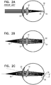
- Fig. 2A is a schematic illustration of light from an ambient scene naturally entering eye 30 and becoming focused, due to natural focusing mechanisms of the eye, on a focus point 42 on a retina 34.
- Figs. 2B-C are schematic illustrations of ray traces produced using the apparatus of Figs. 1A-1B .
- a retinal prosthesis 50 is implanted in eye 30 of the subject, typically but not necessarily, in an epiretinal position.
- Retinal prosthesis 50 is typically configured to receive light beam 40 from power source 24 (shown in Fig. 1A ) and to generate a power signal to power components of prosthesis 50.
- Creating wide, defocused illumination of retina 34 typically improves the effectiveness of power supply to prosthesis 50 and additionally enhances the safety of prosthesis 50.
- a wide, defocused beam 40 onto retina 34 typically improves the effectiveness of power supply to prosthesis 50 during saccadic eye movement. Due to saccadic eye movement, beam 40 is not continuously perfectly aimed at the retina 34. As shown in Fig. 3C , by having a wide, defocused illumination of retina 34, at least a portion of prosthesis 50 is illuminated, i.e., powered by beam 40, during saccadic eye movement. Thus, generally continuous power is provided to prosthesis 50.
- a young human eye is typically capable of focusing through accommodation, which is the process by which the eye changes optical power to maintain a clear focus on an object as its distance varies.
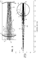
- the minimum focusing distance for a human is 7 cm.
- a beam 45 with a focal point 450 of at least 7 cm or greater from cornea 33 is focused onto the retina, as shown in Fig. 3 .
- an object located at a distance of less than 7 cm from cornea 33 cannot be focused by natural mechanisms of the eye.
- device 20 is configured such that a focal point 400 of beam 40 is located at a distance that is 1-5, e.g., 2 cm, from cornea 33.
- Fig. 4 is a schematic illustration of a typical divergence angle alpha of beam 40.
- Device 20 is typically positioned such that beam 40 diverges at divergence angle alpha of 5-30 degrees, from a focus point (provided by the optics of device 20) that is a distance D1 that is 1-5 cm from cornea 33.
- the divergence angle generally provides that the beam is transmitted through the entire pupil, increasing the amount of power transmitted to the retinal prosthesis.
- Figs. 5A-B Some applications of the present disclosure are configured for use with a corrective optical lens 55.
- Corrective optical lens 55 is typically used for vision correction in the case of common vision disorders such as myopia, hyperopia, astigmatism, or presbyopia.
- extraocular device 20 generally does not obscure the visual field of the subject and is configured to allow visible ambient light rays 145 to enter eye 30, such that visible light emanating from objects is received by prosthesis 50.
- beam 40 emitted from extraocular device 20 e.g., an infrared light beam emitted from power source 24
- does not disrupt ambient light e.g., visible ambient light rays 145, from entering eye 30.
- Corrective optical lens 55 is typically used to facilitate proper receiving of focused ambient light rays by prosthesis 50.
- light passes through cornea 33 and pupil of iris 37, is bent or refracted by lens 32, and comes to a point or focus on retina 34, where the image is formed.
- Fig. 5A is a schematic illustration of eye 30 of a subject suffering from both retinal malfunction and myopia.
- retinal prosthesis 50 is implanted onto retina 34 for treatment of the retinal malfunction.
- light beam 40 from device 20 is emitted towards the eye and lands on retina 34 and prosthesis 50 as a wide defocused beam to power prosthesis 50.
- Visible ambient light rays 145 enter the eye and, due to myopia, are focused in front of retina 34 and prosthesis 50, rather than on the retina and the prosthesis.
- Corrective optical lens 55 shown in Fig. 5B , is typically placed in front of eye 30 of the subject to correct the myopia and thus achieve focusing of visible ambient rays 145 and a focused image on prosthesis 50.
- corrective optical lens 55 is typically coupled to device 20, such that beam 40 does not pass through corrective optical lens 55.
- a light-guiding element 26, e.g., a prism 28 is coupled to eyeglasses frame 22.
- An optical element, e.g. a coupling-in element 62, is positioned to converge beam 40 emitted from power source 24 to a converging light beam.
- Prism 28 is shaped and positioned to convey the converging beam through at least a portion of the prism 28, and arranged such that a diverging beam is conveyed toward the eye of the subject.
- an optical coupling-out element 64 e.g., a dichroic mirror, is optically coupled to prism 28, and the prism is arranged such that the diverging beam is conveyed (a) toward optical coupling-out element 64, and (b) from optical coupling-out element 64 toward eye 30 of the subject, to project a defocused beam 40 on retina 34.
- an optical coupling-out element 64 e.g., a dichroic mirror
- Coupling-in element 62 is positioned such that the beam of light is directed into light-guiding element 26 via the coupling-in element.
- Coupling-in and coupling-out elements 62 and 64 are positioned such that the beam diverges from a focal point located at a distance D2 that is typically within 3 mm of the coupling-out element, to create a defocused light beam which enters the eye.
- Light-guiding element 26 typically has a thickness T1 that is less than 4 mm (e.g., 2-4 mm) at a site of the light-guiding element from which the beam of light exits the light-guiding element.
- the thickness of less than 4 mm of the light-guiding element is maintained also for applications in which a corrective optical lens 55 is optically coupled to the light-guiding element (as shown in Fig. 5B ).
- a corrective optical lens 55 is optically coupled to the light-guiding element (as shown in Fig. 5B ).
- an optical separation e.g., an air gap and/or a dichroic mirror
- the thickness of light-guiding element 26 itself is typically less than 4 mm, regardless of any additional thickness provided by corrective optical lens 55.
- Light-guiding element 26 typically has the above-mentioned thickness T1 that is less than 4 mm over a significant portion of its surface.
- this portion of the surface may have a length L1 that is at least 10 mm.
- L1 is shown extending in a lateral (i.e., left-right) direction.
- This portion of the surface of light-guiding element 26 typically has a length L1 that is at least 10 mm extending in the vertical direction, as well.
- an area of light-guiding element 26, along which the thickness is less than 4 mm is typically at least 100 mm2, e.g., at least 200 mm2.
- Optical coupling-in and coupling-out elements 62 and 64 typically comprise a lens, a mirror, a grating, or a prism.
- the coupling-out element comprises a dichroic mirror (e.g., as shown in Fig 6 ).
- a surface of light-guiding element 26 is shaped to form the optical coupling-in element and/or the coupling-out element.
- elements 62 and/or 64 are structurally separate from (but optically coupled to) light-guiding element 26. It is noted that the use of any combination of coupling-in elements and coupling-out elements as described herein is within the scope of the present invention.
- more than one, but typically not more than ten, coupling-out element are optically coupled to light-guiding element 26.
- the optical coupling-out elements are positioned such that there is a space, D3, of at least 1 mm distance between the optical coupling-out elements, the space not containing an optical coupling-out element. Accordingly, due to the number and spacing of the coupling-out elements, they do not function as pixels for projecting an image towards the eye.
- Extraocular device 20 comprises a user interface element 65 (e.g., a dial, switch, or button), a controller 66 and a modulating unit 68, coupled to eyeglasses frame 22, allowing the subject to interactively control characteristics of the beam emitted from power source 24, e.g., by using the beam to send non-image data to the retinal prosthesis, in addition to transmitting power to the prosthesis.
- a user interface element 65 e.g., a dial, switch, or button
- controller 66 e.g., a controller 66 and a modulating unit 68, coupled to eyeglasses frame 22, allowing the subject to interactively control characteristics of the beam emitted from power source 24, e.g., by using the beam to send non-image data to the retinal prosthesis, in addition to transmitting power to the prosthesis.
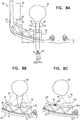
- Fig. 8A is a schematic illustration of apparatus comprising extraocular device 20.
- power source 24 typically an infrared light emitter
- eyeglasses frame 22 is coupled to eyeglasses frame 22 and emits light beam 40 toward light-guiding element 26, e.g., a waveguide or prism.
- Light-guiding element 26 can be either curved or straight, and typically, as noted hereinabove, has a thickness of 1-4 mm, e.g., 2-4 mm.
- Light-guiding element 26 is typically coupled to eyeglasses frame 22 by similar means by which conventional lenses are mounted onto eyeglasses frames.
- the light-guiding element typically directs beam 40 by means of total internal reflection, until the beam leaves element 26.
- Coupling-in element 62 is optically coupled to light-guiding element 26 and is positioned such that beam 40 is directed into light-guiding element 26 via the coupling-in element.
- optical coupling-out element 64 is optically coupled to light-guiding element 26, and is positioned such that beam 40 is directed out of element 26 and into eye 30 of the subject via the coupling-out element.
- Coupling-in and out elements 62 and 64 typically function in order to optimize guiding of beam 40 into and out of guiding element 26.
- suitable coupling-in and coupling-out elements include lenses, gratings, prisms and surface coatings, as well as other passive or active elements.
- Coupling-in and coupling-out elements 62 and 64 are typically used to optimize a shape of beam 40, to reduce light loss when beam 40 enters and leaves guiding element 26, and to direct beam 40 to an appropriate position in eye 30.
- Fig. 8A shows a wide, defocused, diverging light beam 40 entering eye 30 to power prosthesis 50 (e.g., shown in Fig. 2B ). Additionally, as shown, extraocular device 20 does not interfere with visible ambient light rays 145 from entering eye 30 to form an image.
- Fig. 8B is a schematic illustration of apparatus comprising extraocular device 20 configured to simultaneously emit light from a plurality of coupling-out elements, each coupled to the light-guiding element at a discrete location, such that during periods of movement of the eye, beam 40 is generally continuously projected onto prosthesis 50.
- coupling-out elements 72, 74 and 76 shown in Fig. 8B and the use thereof are the same as coupling-out elements 62 and 64, except for differences described below.
- first optical coupling-out element 72 and a second optical coupling-out element 74 are optically coupled to light-guiding element 26 and positioned such that: (a) first optical coupling-out element 72 allows less than all of light beam 40 to leave light-guiding element 26, and (b) second optical coupling-out element 74 allows at least some of the remaining light (in some cases, substantially all of the remaining light) to leave light-guiding element 26.
- first optical coupling-out element 72 redirects remaining light in beam 40 to travel through light-guiding element 26 toward second optical coupling-out element 74.
- first optical coupling-out element 72 allows a first percentage, e.g. 40 - 60%, e.g., 50%, of light from light beam 40 landing on the first optical coupling-out element to leave light-guiding element 26, and second optical coupling-out element 74 allows a second percentage, e.g., substantially 100% of light landing on the second optical coupling-out element, to leave light-guiding element 26.
- the second percentage is higher than the first percentage, e.g., 1.5 - 2.5 times higher than the first percentage.
- the second percentage is the same as the first percentage.
- each optical coupling-out element has suitable optical properties that facilitate the various percentages of transmission.
- a third optical coupling-out element 76 is coupled to light-guiding element 26, and second optical coupling-out element 74 redirects at least a portion of the light in beam 40 to travel through light-guiding element 26 toward third optical coupling-out element 76.
- third optical coupling-out element 76 allows substantially all of the light landing on the third optical coupling-out element to leave light-guiding element 26.
- first optical coupling-out element 72 allows a third of light beam 40 landing on the first optical coupling-out element to leave light-guiding element 26
- second optical coupling-out element 74 allows a half of light beam 40 landing on the second optical coupling-out element to leave the light-guiding element.
- third optical coupling-out element 76 allows substantially all of the light landing on the third optical coupling-out element to leave light-guiding element 26.
- first optical coupling-out element 72 allows a first percentage of light from light beam 40 landing on the first optical coupling-out element to leave light-guiding element 26
- second optical coupling-out element 74 allows a second percentage of light landing on the second optical coupling-out element to leave light-guiding element 26
- third optical coupling-out element 76 allows a third percentage of light landing on the third optical coupling-out element to leave the light-guiding element.
- the third percentage is higher than the second percentage, and the second percentage is higher than the first percentage.
- one or more sensors 80 are coupled to light-guiding element 26 or elsewhere on device 20, and identify a gaze direction of the subject and generate a signal in response thereto.
- extraocular device 20 determines which of first and second optical coupling-out elements 720 and 740 (or, for some cases, also a third coupling-out element 760) are generally in the gaze of the subject, and allows light beam 40 (from power source 24) to leave light-guiding element 26 toward eye 30 through the coupling-out element situated in the gaze of the subject.
- device 20 increases the effectiveness of power supply to implantable prosthesis 50, by generally directing a larger portion of a smaller beam 40 toward prosthesis 50 than in applications in which a larger beam 40 is utilized to provide power to prosthesis 50 regardless of gaze direction.
- extraocular device 20 comprises a switch 81, disposed within a housing of sensor 80 or elsewhere in device 20.
- Switch 81 receives the signal generated in response to identifying the gaze direction of the subject and in response to receiving the signal, switches at least first coupling-out element 720 between (a) a transmissive mode, in which the first coupling-out element facilitates light from beam 40 of light leaving light-guiding element 26 and going toward eye 30 and (b) a reflective mode, in which first coupling-out element 720 facilitates light from beam 40 of light going toward second coupling-out element 740 and inhibits light from beam 40 of light from leaving light-guiding element 26 and going toward eye 30.
- one or more sensors 80 are configured to identify a gaze direction of the subject by receiving a reflection of beam 40 which is reflected from intraocular prosthesis 50 (shown in Figs. 2B-C ).
- one or more sensors 80 comprise an infrared camera configured to identify the gaze direction of the subject. It is noted that the infrared camera identifies and tracks the gaze of the subject, but typically does not image a scene and does not project an image toward the subject's eye.
- coupling-out elements 720, 740 and 760 shown in Fig. 8C are the same as coupling-out elements 62 and 64, except for differences described hereinabove with reference to Fig. 8C .
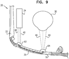
- light-guiding element 26 comprises an optical fiber 29.
- an eyeglasses lens e.g., corrective optical lens 55 is coupled to frame 22, and optical fiber 29 is embedded within the eyeglasses lens and positioned to emit light toward eye 30 of the subject.
- power source 24 which is coupled to eyeglasses frame 22, emits a beam of light 40 that is outside of 380-750 nm.
- Extraocular device 20 is configured to direct light beam 40 out of power source 24 and into optical fiber 29. For some applications directing of light beam 40 into optical fiber 29 is facilitated by optical coupling-in element 62 and/or light beam 40 leaves fiber 29 via optical coupling-out element 64.
- power coupling-in element 62 comprises a pigtail diode, positioned to direct light beam 40 into fiber 29.
- beam 40 enters optical fiber 29 through optical coupling-in element 62 as a collimated beam, and leaves optical fiber 29 through optical coupling-out element 64 as a diverging beam. Accordingly, beam 40 enters eye 30 as a defocused beam. Alternatively, beam 40 leaving coupling-out element 64 converges to a point in space between element 64 and eye 30, and subsequently diverges as it enters the eye (configuration not shown).
- light-guiding element 26 may comprise an optical fiber 29 also in other configurations, e.g., as shown with reference to Figs. 6 , 8A-C , and 10A-B .
- extraocular device 20 configured to apply power to the prosthesis through a plurality of optical coupling-out elements, such that retinal prosthesis 50 (shown in Figs. 2B-C ) is generally continuously powered during a period of eye movements.
- extraocular device 20 comprises a plurality of power sources 24, each configured to emit light that enters light-guiding element 26 through optical coupling-in element 62 and leaves light-guiding element 26 through a discrete optical coupling-out element.
- extraocular device 20 comprises optical coupling-out elements 1720, 1740, and 1760, which are optically coupled to discrete locations of element 26 such that when a gaze of the subject changes, power still enters eye 30 through at least one of the optical coupling-out elements.
- coupling-out elements 1720, 1740 and 1760 shown in Figs. 10A-B are the same as coupling-out elements 62 and 64, except for differences described herein with reference to Figs. 10A-B .
- extraocular device 20 comprises one or more eye-tracking sensors (e.g., as shown in Fig. 8C ), which are coupled to light-guiding element 26 or elsewhere on device 20, and identify a gaze direction of the subject and generate a signal in response thereto.
- eye-tracking sensors e.g., as shown in Fig. 8C
- extraocular device 20 determines which of optical coupling-out elements 1720 and/or 1740 and/or 1760 are generally in the gaze of the subject, and causes light beam 40 to leave light-guiding element 26 toward eye 30 through the coupling-out element situated in the gaze of the subject, and typically not through a coupling-out element not situated in the gaze of the subject.
- extraocular device 20 comprises a single power source 24 and a beam director 84, which is configured to direct beam 40 to each of the optical coupling-out elements.
- beam director 84 may comprise a modulator, e.g., an acousto-optic modulator, configured to diffract and shift the frequency of light to create multiple beams 40 and achieve an effect of multiple non-simultaneous beams, as described hereinabove with reference to Fig. 10A .
- device 20 comprises one or more sensors (e.g., as shown in Fig.
- extraocular device 20 determines which one of the plurality of optical coupling-out elements 1720 and/or 1740 and/or 1760 are generally in the gaze of the subject, and causes beam director 84, e.g., modulator 84, to direct a light beam 40 to leave light-guiding element 26 toward eye 30 through the coupling-out element situated in the gaze of the subject, and typically inhibit the light beam from leaving the light-guiding element toward the eye through a coupling-out element not situated in the gaze of the subject.
- beam director 84 e.g., modulator 84
- beam director 84 is passive, e.g., it may comprise a beam-splitter, which simultaneously directs beam 40 to each of the coupling-out elements.
- Prosthesis 50 typically comprises an intraocular device.
- the intraocular device typically comprises an energy receiver, which receives the beam of light from the power source and generates a voltage drop in response thereto; a plurality of stimulating electrodes; a plurality of photosensors, which detect photons and generate a signal in response thereto; and driving circuitry, coupled to the energy receiver and to the photosensors, which receives the signals from the photosensors and utilizes the voltage drop to drive the electrodes to apply currents to retina 34 in response to the signals from the photosensors.
Landscapes
- Physics & Mathematics (AREA)
- Health & Medical Sciences (AREA)
- General Physics & Mathematics (AREA)
- Optics & Photonics (AREA)
- General Health & Medical Sciences (AREA)
- Ophthalmology & Optometry (AREA)
- Nuclear Medicine, Radiotherapy & Molecular Imaging (AREA)
- Biomedical Technology (AREA)
- Engineering & Computer Science (AREA)
- Radiology & Medical Imaging (AREA)
- Life Sciences & Earth Sciences (AREA)
- Animal Behavior & Ethology (AREA)
- Public Health (AREA)
- Veterinary Medicine (AREA)
- Acoustics & Sound (AREA)
- Otolaryngology (AREA)
- Prostheses (AREA)
- Eye Examination Apparatus (AREA)
Claims (14)
- Vorrichtung, die eine extraokulare Einrichtung (20) umfasst, die Folgendes umfasst:ein Brillengestell (22), das konfiguriert ist, um vor einem Auge eines Subjekts platziert zu werden;eine Stromquelle (24), die an das Brillengestell (22) gekoppelt ist und konfiguriert ist, um einen Strahl (40) von Licht auszustrahlen, das außerhalb von 380 bis 750 nm ist;ein lichtleitendes Element (26), das an das Brillengestell (22) gekoppelt ist; undmindestens ein optisches Einkoppelelement (62) und mindestens ein optisches Auskoppelelement (64), die optisch an das lichtleitende Element (26) gekoppelt sind,wobei das Einkoppelelement (62) so positioniert ist, dass der Strahl (40) von Licht über das Einkoppelelement (62) in das lichtleitende Element (26) gerichtet wird,dadurch gekennzeichnet, dass das Einkoppel- und das Auskoppelelement (62, 64) positioniert sind, sodass der Strahl (40) von einem Brennpunkt divergiert, der sich in einem optischen Weg zwischen dem Einkoppel- und dem Auskoppelelement (62, 64) befindet und mit einem Abstand, der innerhalb von 3 mm von dem Auskoppelelement (64) ist.
- Vorrichtung nach Anspruch 1, wobei die Stromquelle (24) einen Laser umfasst.
- Vorrichtung nach Anspruch 1, wobei das Einkoppel- und das Auskoppelelement (62, 64) positioniert sind, um einen defokussierten Lichtpunkt auf einer Bindehaut des Subjekts zu erzeugen.
- Vorrichtung nach Anspruch 1, wobei eine Fläche des lichtleitenden Elements (26) geformt ist, um das optische Einkoppelelement (62) zu bilden.
- Vorrichtung nach Anspruch 1, wobei eine Fläche des lichtleitenden Elements (26) geformt ist, um das optische Auskoppelelement (64) zu bilden.
- Vorrichtung nach Anspruch 1, wobei das Einkoppel- und das Auskoppelelement (62, 64) positioniert sind, sodass der Strahl (40) mit einem Divergierungswinkel von 5 bis 30 Grad divergiert.
- Vorrichtung nach Anspruch 1, wobei die extraokulare Einrichtung (20) keine Kamera umfasst.
- Vorrichtung nach Anspruch 1, wobei die extraokulare Einrichtung (20) nicht konfiguriert ist, um ein aus Pixeln bestehendes Bild zu projizieren.
- Vorrichtung nach Anspruch 1, wobei die extraokulare Einrichtung (20) konfiguriert ist, um es Umgebungslicht zu ermöglichen, in das Auge zu fallen.
- Vorrichtung nach Anspruch 1, wobei das lichtleitende Element (26) ein Prisma (28) umfasst.
- Vorrichtung nach einem der Ansprüche 1 bis 10, wobei das optische Einkoppelelement (62) aus der Gruppe ausgewählt ist, die aus Folgenden besteht: eine Linse, ein Spiegel, ein Gitter und ein Prisma.
- Vorrichtung nach einem der Ansprüche 1 bis 10, wobei das Auskoppelelement (64) einen dichroitischen Spiegel umfasst.
- Vorrichtung nach einem der Ansprüche 1 bis 10, wobei das lichtleitende Element (26) eine Glasfaser umfasst.
- Vorrichtung nach Anspruch 13, wobei das Brillengestell (22) eine Brillenlinse umfasst und wobei die Glasfaser in der Brillenlinse eingebettet ist.
Applications Claiming Priority (2)
| Application Number | Priority Date | Filing Date | Title |
|---|---|---|---|
| US14/145,470 US9474902B2 (en) | 2013-12-31 | 2013-12-31 | Wearable apparatus for delivery of power to a retinal prosthesis |
| PCT/IB2014/067417 WO2015101932A2 (en) | 2013-12-31 | 2014-12-30 | Wearable apparatus for delivery of power to a retinal prosthesis |
Publications (2)
| Publication Number | Publication Date |
|---|---|
| EP3089784A2 EP3089784A2 (de) | 2016-11-09 |
| EP3089784B1 true EP3089784B1 (de) | 2018-09-19 |
Family
ID=52350170
Family Applications (1)
| Application Number | Title | Priority Date | Filing Date |
|---|---|---|---|
| EP14827551.4A Not-in-force EP3089784B1 (de) | 2013-12-31 | 2014-12-30 | Tragbare vorrichtung zur abgabe von energie an eine retinaprothese |
Country Status (4)
| Country | Link |
|---|---|
| US (1) | US9474902B2 (de) |
| EP (1) | EP3089784B1 (de) |
| CN (2) | CN205007073U (de) |
| WO (1) | WO2015101932A2 (de) |
Families Citing this family (35)
| Publication number | Priority date | Publication date | Assignee | Title |
|---|---|---|---|---|
| IL166799A (en) | 2005-02-10 | 2014-09-30 | Lumus Ltd | Aluminum shale surfaces for use in a conductive substrate |
| IL235642B (en) | 2014-11-11 | 2021-08-31 | Lumus Ltd | A compact head-up display system is protected by an element with a super-thin structure |
| WO2017100545A1 (en) | 2015-12-10 | 2017-06-15 | Nano-Retina, Inc. | Techniques for data retention in memory cells during power interruption |
| CN105435379B (zh) * | 2015-12-29 | 2018-11-02 | 深圳先进技术研究院 | 基于二维面阵探头的视网膜刺激设备 |
| CN105662704B (zh) * | 2015-12-29 | 2017-10-20 | 深圳先进技术研究院 | 超声视网膜刺激设备 |
| CN105404027B (zh) * | 2015-12-31 | 2018-09-11 | 白云供电局 | 一种无线充电wifi摄像眼镜及配套的无线供电装置 |
| DE102016103285A1 (de) * | 2016-02-24 | 2017-08-24 | Carl Zeiss Ag | Vorrichtung und Verfahren zur Versorgung eines Retinaimplantats |
| KR102549713B1 (ko) | 2016-05-18 | 2023-06-29 | 루머스 리미티드 | 헤드 장착식 이미징 장치 |
| JP7187022B2 (ja) | 2016-10-09 | 2022-12-12 | ルムス エルティーディー. | 長方形導波路を使用する開口乗算器 |
| US10226625B2 (en) | 2016-11-03 | 2019-03-12 | Nano Retina Ltd. | Surgical techniques for implantation of a retinal implant |
| US10272244B2 (en) | 2016-11-03 | 2019-04-30 | Nano Retina Ltd. | Retinal implant fixation |
| KR102541662B1 (ko) | 2016-11-08 | 2023-06-13 | 루머스 리미티드 | 광학 컷오프 에지를 구비한 도광 장치 및 그 제조 방법 |
| WO2018140938A1 (en) | 2017-01-30 | 2018-08-02 | The Charles Stark Draper Laboratory, Inc. | Saw modulators and light steering methods |
| KR102906823B1 (ko) * | 2017-02-13 | 2025-12-31 | 시리얼 테크놀로지즈 에스.에이. | 광 가이드 디바이스 및 장면을 표현하기 위한 디스플레이 디바이스 |
| TWI754010B (zh) | 2017-02-22 | 2022-02-01 | 以色列商魯姆斯有限公司 | 導光光學組件 |
| DE102017107346A1 (de) * | 2017-04-05 | 2018-10-11 | Carl Zeiss Ag | Vorrichtung zur Energieversorgung von und/oder Kommunikation mit einem Augenimplantat mittels Beleuchtungsstrahlung |
| IL251645B (en) * | 2017-04-06 | 2018-08-30 | Lumus Ltd | Waveguide and method of production |
| WO2019016813A1 (en) | 2017-07-19 | 2019-01-24 | Lumus Ltd. | LIQUID CRYSTAL LIGHTING ON SILICON VIA OPTICAL ELEMENT GUIDE OF LIGHT |
| CN111316153B (zh) | 2017-09-21 | 2025-03-18 | 奇跃公司 | 具有被配置为捕获眼睛和/或环境的图像的波导的增强现实显示器 |
| US11092810B2 (en) | 2017-11-21 | 2021-08-17 | Lumus Ltd. | Optical aperture expansion arrangement for near-eye displays |
| US10583283B2 (en) | 2018-01-31 | 2020-03-10 | Nano-Retina, Inc. | Retinal implant with image registration |
| FI128552B (en) * | 2018-03-28 | 2020-07-31 | Dispelix Oy | Waveguide display element with reflector surface |
| US11415812B2 (en) | 2018-06-26 | 2022-08-16 | Lumus Ltd. | Compact collimating optical device and system |
| JP7376578B2 (ja) | 2018-09-26 | 2023-11-08 | マジック リープ, インコーポレイテッド | ピンホールおよびスリットカメラを伴うアイウェア |
| DE102019108678A1 (de) * | 2019-04-03 | 2020-10-08 | Carl Zeiss Ag | Vorrichtung zur Energieversorgung eines aktiven Augenimplantats |
| DE102019108679A1 (de) | 2019-04-03 | 2020-10-08 | Carl Zeiss Ag | Vorrichtungen zur Energieversorgung eines aktiven Augenimplantats |
| TWI916247B (zh) | 2019-04-15 | 2026-02-21 | 以色列商魯姆斯有限公司 | 光導光學元件 |
| KR20220024410A (ko) | 2019-06-27 | 2022-03-03 | 루머스 리미티드 | 도광 광학 소자를 통한 눈 이미징에 기초한 시선 추적 장치 및 방법 |
| KR20220035088A (ko) | 2019-07-18 | 2022-03-21 | 루머스 리미티드 | 캡슐화된 도광 광학 소자 |
| US11561336B2 (en) | 2019-10-05 | 2023-01-24 | Meta Platforms Technologies, Llc | Transparent illumination layer with transparent waveguide structure |
| JP7396738B2 (ja) | 2019-12-05 | 2023-12-12 | ルーマス リミテッド | 相補的コーティング部分的反射器を用いた導光光学素子および低減された光散乱を有する導光光学素子 |
| EP4078271A1 (de) * | 2019-12-20 | 2022-10-26 | Nano Retina Ltd. | Verfahren zum herstellen eines brillenglases zum bereitstellen von licht für ein auge, rohling und brillenglassatz |
| EP4099968A4 (de) | 2020-03-23 | 2024-03-06 | Tectus Corporation | Elektronische intraokulare vorrichtungen |
| EP4256396A4 (de) | 2021-07-04 | 2024-05-29 | Lumus Ltd. | Anzeige mit gestapelten lichtleiterelementen zur bereitstellung verschiedener sichtfeldteile |
| CN115624381B (zh) * | 2022-12-12 | 2023-05-09 | 北京国光领航科技有限公司 | 一种具有安全检测系统的激光医疗装置 |
Family Cites Families (282)
| Publication number | Priority date | Publication date | Assignee | Title |
|---|---|---|---|---|
| US1662446A (en) | 1924-01-14 | 1928-03-13 | Wappler Electric Company Inc | Metal-foil electrode |
| US2721316A (en) | 1953-06-09 | 1955-10-18 | Joseph D Shaw | Method and means for aiding the blind |
| US2760483A (en) | 1953-10-29 | 1956-08-28 | Tassicker Graham Edward | Retinal stimulator |
| JPS5429639A (en) | 1977-08-09 | 1979-03-05 | Ricoh Co Ltd | Mulistylus electrostatic recording method |
| US4197850A (en) | 1978-11-03 | 1980-04-15 | Pacesetter Systems, Inc. | Implantable human tissue stimulator with memory protect means |
| US4272910A (en) | 1979-07-31 | 1981-06-16 | Danz W R | Ocular prosthetic or the like |
| US4324252A (en) | 1980-08-04 | 1982-04-13 | Medtronic, Inc. | Memory control circuitry for implantable medical devices |
| US4551149A (en) | 1982-02-16 | 1985-11-05 | Michael Sciarra | Prosthetic vision system |
| US4601545A (en) | 1984-05-16 | 1986-07-22 | Kern Seymour P | Variable power lens system |
| US4664117A (en) | 1984-10-09 | 1987-05-12 | Beck Stephen C | Apparatus and method for generating phosphenes |
| US4628933A (en) | 1985-07-23 | 1986-12-16 | Michelson Robin P | Method and apparatus for visual prosthesis |
| US4969468A (en) | 1986-06-17 | 1990-11-13 | Alfred E. Mann Foundation For Scientific Research | Electrode array for use in connection with a living body and method of manufacture |
| US4837049A (en) | 1986-06-17 | 1989-06-06 | Alfred E. Mann Foundation For Scientific Research | Method of making an electrode array |
| JPH0758226B2 (ja) | 1987-09-10 | 1995-06-21 | 富士写真フイルム株式会社 | 光源検出装置 |
| US4786818A (en) | 1987-11-09 | 1988-11-22 | California Institute Of Technology | Integrated sensor and processor for visual images |
| US4903702A (en) | 1988-10-17 | 1990-02-27 | Ad-Tech Medical Instrument Corporation | Brain-contact for sensing epileptogenic foci with improved accuracy |
| US5159927A (en) | 1989-07-26 | 1992-11-03 | Ferdinand Schmid | Visual prosthesis apparatus and method |
| US5024223A (en) | 1989-08-08 | 1991-06-18 | Chow Alan Y | Artificial retina device |
| US5016633A (en) | 1989-08-08 | 1991-05-21 | Chow Alan Y | Artificial retina device |
| RU1799577C (ru) | 1989-08-17 | 1993-03-07 | Межотраслевой научно-технический комплекс "Микрохирургия глаза" | Способ улучшени зрительных функций при заболевани х зрительного нерва и сетчатки и устройство дл его осуществлени |
| US5215088A (en) | 1989-11-07 | 1993-06-01 | The University Of Utah | Three-dimensional electrode device |
| JPH0671186B2 (ja) | 1990-01-19 | 1994-09-07 | 株式会社東芝 | 対数増幅回路 |
| US5314458A (en) | 1990-06-01 | 1994-05-24 | University Of Michigan | Single channel microstimulator |
| US5313642A (en) | 1990-10-03 | 1994-05-17 | Seagull Scientific Systems, Inc. | Power interface for peripheral devices |
| US5109844A (en) | 1990-10-11 | 1992-05-05 | Duke University | Retinal microstimulation |
| US5108427A (en) | 1991-01-07 | 1992-04-28 | Majercik Stephen M | Active pupillary prosthesis |
| US5133356A (en) | 1991-04-16 | 1992-07-28 | Minnesota Mining And Manufacturing Company | Biomedical electrode having centrally-positioned tab construction |
| US5526423A (en) | 1991-05-08 | 1996-06-11 | Canon Kabushiki Kaisha | Communication apparatus and method with service execution according to dial number |
| DE4209536C3 (de) | 1992-03-24 | 2000-10-05 | Stuttgart Mikroelektronik | Bildzelle für einen Bildaufnehmer-Chip |
| US5476494A (en) | 1992-09-11 | 1995-12-19 | Massachusetts Institute Of Technology | Low pressure neural contact structure |
| US5397350A (en) | 1993-05-03 | 1995-03-14 | Chow; Alan Y. | Independent photoelectric artificial retina device and method of using same |
| US5556423A (en) | 1993-05-03 | 1996-09-17 | Alan Y. Chow | Independent photoelectric artificial retina device and method of using same |
| US5597381A (en) | 1993-06-03 | 1997-01-28 | Massachusetts Eye And Ear Infirmary | Methods for epi-retinal implantation |
| US5411540A (en) | 1993-06-03 | 1995-05-02 | Massachusetts Institute Of Technology | Method and apparatus for preferential neuron stimulation |
| US5800535A (en) | 1994-02-09 | 1998-09-01 | The University Of Iowa Research Foundation | Wireless prosthetic electrode for the brain |
| US5769875A (en) | 1994-09-06 | 1998-06-23 | Case Western Reserve University | Functional neuromusclar stimulation system |
| JPH08297465A (ja) | 1995-04-26 | 1996-11-12 | Hiroshi Yamamoto | 視神経映像出力装置とその方法 |
| CA2222741C (en) | 1995-06-06 | 2002-05-28 | Vincent Chow | Multi-phasic microphotodiode retinal implant and adaptive imaging retinal stimulation system |
| US5895415A (en) | 1995-06-06 | 1999-04-20 | Optobionics Corporation | Multi-phasic microphotodiode retinal implant and adaptive imaging retinal stimulation system |
| US5805267A (en) | 1996-06-13 | 1998-09-08 | Goldman; Neil | Interactive light field for programmed non-visual stimulation and monitoring |
| US5873901A (en) | 1995-06-30 | 1999-02-23 | Space Vacuum Epitaxy Center University Of Houston | Treating retinal damage by implanting thin film optical detectors |
| DE19529371C3 (de) | 1995-08-10 | 2003-05-28 | Nmi Univ Tuebingen | Mikroelektroden-Anordnung |
| JPH0964441A (ja) | 1995-08-23 | 1997-03-07 | Fujitsu Ltd | 発光素子駆動装置 |
| CA2235216C (en) | 1995-10-19 | 2006-05-30 | The University Of Melbourne | Embedded data link and protocol |
| JP4036896B2 (ja) | 1995-12-01 | 2008-01-23 | キネティック リミテッド | イメージングシステム |
| US5800478A (en) | 1996-03-07 | 1998-09-01 | Light Sciences Limited Partnership | Flexible microcircuits for internal light therapy |
| US5800533A (en) | 1996-03-18 | 1998-09-01 | Harry C. Eggleston | Adjustable intraocular lens implant with magnetic adjustment facilities |
| JP3633092B2 (ja) | 1996-03-18 | 2005-03-30 | 日産自動車株式会社 | マイコン故障監視装置 |
| DE19639644A1 (de) | 1996-09-26 | 1998-04-02 | Siemens Ag | Verfahren und Anordnung zur Steuerung von Funktionen in einer programmgesteuerten Schaltungsanordnung bei Ausfall der Betriebsspannung |
| EP0951312B1 (de) | 1996-10-23 | 2005-04-06 | Nmi Naturwissenschaftliches Und Medizinisches Institut An Der Universität Tübingen | Optisch ansteuerbare mikroelektrodenanordnung zum stimulieren von zellen, insbesondere retina-implantat |
| DE19705988C2 (de) | 1996-10-23 | 2002-04-11 | Univ Eberhard Karls | Retina-Implantat |
| US5735882A (en) | 1996-11-25 | 1998-04-07 | Sulzer Intermedics Inc. | Cardiac stimulator with backup-mode self-recovery |
| US5837995A (en) | 1996-11-25 | 1998-11-17 | Alan Y. Chow | Wavelength-controllable voltage-phase photodiode optoelectronic switch ("opsistor") |
| US6043437A (en) | 1996-12-20 | 2000-03-28 | Alfred E. Mann Foundation | Alumina insulation for coating implantable components and other microminiature devices |
| US5865839A (en) | 1996-12-30 | 1999-02-02 | Doorish; John F. | Artificial retina |
| US5836996A (en) | 1996-12-30 | 1998-11-17 | Doorish; John F. | Artificial retina |
| DE19707046A1 (de) | 1997-02-21 | 1998-08-27 | Rolf Prof Dr Ing Eckmiller | Lernfähiger "Active Vision" Implant Encoder |
| US6458157B1 (en) | 1997-08-04 | 2002-10-01 | Suaning Gregg Joergen | Retinal stimulator |
| US6259937B1 (en) | 1997-09-12 | 2001-07-10 | Alfred E. Mann Foundation | Implantable substrate sensor |
| DE19741487C2 (de) | 1997-09-19 | 2000-08-31 | Univ Eberhard Karls | Vorrichtung für einen Zugang in den Subretinalraum eines Auges |
| US6069365A (en) | 1997-11-25 | 2000-05-30 | Alan Y. Chow | Optical processor based imaging system |
| US6235046B1 (en) | 1998-01-21 | 2001-05-22 | David W. Gerdt | Passive photonic eye delivery system |
| US5935155A (en) | 1998-03-13 | 1999-08-10 | John Hopkins University, School Of Medicine | Visual prosthesis and method of using same |
| US5944747A (en) | 1998-03-13 | 1999-08-31 | Johns Hopkins University | Method for preferential outer retinal stimulation |
| US6324429B1 (en) | 1998-05-08 | 2001-11-27 | Massachusetts Eye And Ear Infirmary | Chronically implantable retinal prosthesis |
| US6035236A (en) | 1998-07-13 | 2000-03-07 | Bionergy Therapeutics, Inc. | Methods and apparatus for electrical microcurrent stimulation therapy |
| EP1113840A1 (de) | 1998-07-27 | 2001-07-11 | J. Thomas Mortimer | Gerät und verfahren zum hervorrufen visueller empfindungen durch stimulieren des sehnervs |
| US6165192A (en) | 1999-01-05 | 2000-12-26 | Second Sight, Llc | Method and apparatus for intraocular retinal tack inserter |
| DE19911103B4 (de) | 1999-03-12 | 2005-06-16 | MAX-PLANCK-Gesellschaft zur Förderung der Wissenschaften e.V. | Erzeugung stabilisierter, ultrakurzer Lichtpulse und deren Anwendung zur Synthese optischer Frequenzen |
| US8180453B2 (en) | 1999-03-24 | 2012-05-15 | Second Sight Medical Products, Inc. | Electrode array for neural stimulation |
| US6507758B1 (en) | 1999-03-24 | 2003-01-14 | Second Sight, Llc | Logarithmic light intensifier for use with photoreceptor-based implanted retinal prosthetics and those prosthetics |
| DE60042155D1 (de) | 1999-03-24 | 2009-06-18 | Second Sight Medical Prod Inc | Retinale farbprothese zur wiederherstellung des farbsehens |
| DE19921399C2 (de) | 1999-05-07 | 2003-12-18 | Univ Eberhard Karls | Retina-Implantat |
| EP1178763B1 (de) | 1999-05-07 | 2008-12-10 | Retina Implant AG | Retina-implantat und verfahren zur herstellung eines solchen |
| JP3685956B2 (ja) | 1999-06-11 | 2005-08-24 | 住友重機械工業株式会社 | 眼球照射線の制御装置 |
| US6888571B1 (en) | 1999-09-27 | 2005-05-03 | Casio Computer Co., Ltd. | Photosensor system and drive control method thereof |
| DE19959881C1 (de) | 1999-12-13 | 2001-10-18 | Cindatec Ingenieurtechnische D | Verfahren und Anordnung zur Bestimmung der Topographie für Reaktionssignale eines Auges |
| US6319273B1 (en) | 1999-12-16 | 2001-11-20 | Light Sciences Corporation | Illuminating device for treating eye disease |
| US6658299B1 (en) | 2000-01-04 | 2003-12-02 | William H. Dobelle | Artificial system for vision and the like |
| US7013179B2 (en) | 2000-01-07 | 2006-03-14 | Biowave Corporation | Percutaneous electrode array |
| US6829498B2 (en) | 2000-03-29 | 2004-12-07 | Arizona Board Of Regents | Device for creating a neural interface and method for making same |
| US6287372B1 (en) | 2000-03-31 | 2001-09-11 | Themec Company Incorporated | Anti-corrosive coating |
| US6389317B1 (en) | 2000-03-31 | 2002-05-14 | Optobionics Corporation | Multi-phasic microphotodetector retinal implant with variable voltage and current capability |
| US6427087B1 (en) | 2000-05-04 | 2002-07-30 | Optobionics Corporation | Artificial retina device with stimulating and ground return electrodes disposed on opposite sides of the neuroretina and method of attachment |
| AU6419701A (en) | 2000-05-31 | 2001-12-11 | Impulse Dynamics N.V. | Electropancreatography |
| US6677225B1 (en) | 2000-07-14 | 2004-01-13 | Zyvex Corporation | System and method for constraining totally released microcomponents |
| KR100381890B1 (ko) | 2000-08-04 | 2003-04-26 | 국방과학연구소 | 선배열 소나 시스템의 수중청음기 지지구조 |
| US6647297B2 (en) | 2000-08-09 | 2003-11-11 | The United States Of America As Represented By The Secretary Of The Navy | Permanent retinal implant device |
| US6970745B2 (en) | 2000-08-09 | 2005-11-29 | The United States Of America As Represented By The Secretary Of The Navy | Microelectronic stimulator array for stimulating nerve tissue |
| GB2370509A (en) | 2000-08-29 | 2002-07-03 | Don Edward Casey | Subcutaneously implanted photovoltaic power supply |
| ATE336279T1 (de) | 2000-11-16 | 2006-09-15 | Polyvalor Sec | Elektronisches körperimplantat und system zum künstlichen sehen |
| US6368349B1 (en) | 2000-11-21 | 2002-04-09 | Massachusetts Institute Of Technology | Inflatable neural prosthesis |
| WO2002055151A1 (de) | 2001-01-11 | 2002-07-18 | Fraunhofer-Gesellschaft zur Förderung der angewandten Forschung e.V. | Siebelektrode zur anbindung an einen nervenstumpf |
| US7103416B2 (en) | 2001-01-16 | 2006-09-05 | Second Sight Medical Products, Inc. | Visual prosthesis including enhanced receiving and stimulating portion |
| US6758823B2 (en) | 2001-02-09 | 2004-07-06 | Massachusetts Eye & Ear Infirmary | Assessment of retinal function |
| US8060211B2 (en) | 2001-02-13 | 2011-11-15 | Second Sight Medical Products, Inc. | Method of reducing retinal stress caused by an implantable retinal electrode array |
| US7149586B2 (en) | 2002-03-28 | 2006-12-12 | Second Sight Medical Products, Inc. | Variable pitch electrode array |
| US7127286B2 (en) | 2001-02-28 | 2006-10-24 | Second Sight Medical Products, Inc. | Implantable device using ultra-nanocrystalline diamond |
| JP4781576B2 (ja) | 2001-02-28 | 2011-09-28 | 株式会社ニデック | 眼内埋め込み型視覚刺激装置 |
| US6574022B2 (en) | 2001-03-19 | 2003-06-03 | Alan Y. Chow | Integral differential optical signal receiver |
| US7248928B2 (en) | 2001-03-30 | 2007-07-24 | Nidek Co., Ltd. | Artificial eye system |
| US7158836B2 (en) | 2001-03-30 | 2007-01-02 | Satoshi Suzuki | Electrode member for retinal stimulation, and artificial retinal device using the electrode member |
| US7480988B2 (en) | 2001-03-30 | 2009-01-27 | Second Sight Medical Products, Inc. | Method and apparatus for providing hermetic electrical feedthrough |
| US6609840B2 (en) | 2001-04-05 | 2003-08-26 | Alan Y. Chow | Wave length associative addressing system for WDM type light packet steering |
| US7037943B2 (en) | 2001-04-10 | 2006-05-02 | Optobionics Corporation | Retinal treatment method |
| DE10120083A1 (de) | 2001-04-17 | 2003-01-30 | Nmi Univ Tuebingen | Meßelektrodenpaar, Biosensor mit einem solchen Meßelektrodenpaar und Verfahren zur Herstellung |
| DE10120908A1 (de) | 2001-04-28 | 2002-10-31 | Td Verwaltungs Gmbh | Mikrokontaktstruktur zur Implantation bei einem Säugetier, insbesondere bei einem Menschen |
| AU2002305357A1 (en) | 2001-05-01 | 2002-11-11 | Second Sight, Llc | High-density array of micro-machined electrodes for neural stimulation |
| US6792314B2 (en) | 2001-06-18 | 2004-09-14 | Alfred E. Mann Foundation For Scientific Research | Miniature implantable array and stimulation system suitable for eyelid stimulation |
| US6738672B2 (en) | 2001-06-18 | 2004-05-18 | The Alfred E. Mann Foundation For Scientific Research | Miniature implantable connectors |
| DE60215029T2 (de) | 2001-06-29 | 2007-10-25 | The Board Of Trustees Of The Leland Stanford Junior University, Palo Alto | Kunstmässige chip-schnittstellenverbindung für elektronische reitinaimplantat |
| US7147865B2 (en) | 2001-06-29 | 2006-12-12 | The Board Of Trustees Of The Leland Stanford University | Artificial synapse chip |
| US7556621B2 (en) | 2001-06-29 | 2009-07-07 | The Board Of Trustees Of The Leland Stanford Junior University | Optically controlled microfluidic chip |
| US7031776B2 (en) | 2001-06-29 | 2006-04-18 | Optobionics | Methods for improving damaged retinal cell function |
| US6678458B2 (en) | 2001-08-17 | 2004-01-13 | Zynex Corporation | System and method for precise positioning of microcomponents |
| US7295872B2 (en) | 2001-10-10 | 2007-11-13 | Massachusetts Institute Of Technology | System for and method of power efficient electrical tissue stimulation |
| US6949763B2 (en) | 2001-10-11 | 2005-09-27 | Marc Ovadia | Semiconductor and non-semiconductor non-diffusion-governed bioelectrodes |
| AU2002348971A1 (en) | 2001-10-12 | 2003-04-28 | Stefana M. Petrescu | Ph-sensitive liposomes for targeted drug delivery |
| DE10151650A1 (de) | 2001-10-17 | 2003-05-08 | Univ Eberhard Karls | Elektrodenanordnung zur elektrischen Stimulation von biologischem Material sowie Multielektrodenarray zur Verwendung in einer solchen |
| JP3883126B2 (ja) | 2001-10-26 | 2007-02-21 | 富士通株式会社 | 半導体集積回路装置、それが組み込まれた電子装置、及び消費電力低減方法 |
| US20030086064A1 (en) | 2001-11-06 | 2003-05-08 | Sutter Erich E | Head mounted infrared fundus illuminator |
| DE10154700A1 (de) | 2001-11-09 | 2003-05-22 | Iip Technologies Gmbh | Retinaimplantat mit verbesserten Implantations- und Nutzungseigenschaften |
| US7146221B2 (en) | 2001-11-16 | 2006-12-05 | The Regents Of The University Of California | Flexible electrode array for artifical vision |
| US6770521B2 (en) | 2001-11-30 | 2004-08-03 | Texas Instruments Incorporated | Method of making multiple work function gates by implanting metals with metallic alloying additives |
| AU2002364712A1 (en) | 2001-11-30 | 2003-06-17 | Second Sight, Llc | Floating gate digital-to-analog converter |
| US7853330B2 (en) | 2001-12-04 | 2010-12-14 | Boston Scientific Neuromodulation Corporation | Apparatus and method for determining the relative position and orientation of neurostimulation leads |
| US6891549B2 (en) | 2002-01-11 | 2005-05-10 | Applied Materials, Inc. | System and method for edge enhancement of images |
| WO2003063242A1 (en) | 2002-01-16 | 2003-07-31 | Alfred E. Mann Foundation For Scientific Research | Space-saving packaging of electronic circuits |
| US6976998B2 (en) | 2002-01-17 | 2005-12-20 | Massachusetts Institute Of Technology | Minimally invasive retinal prosthesis |
| CN1639799A (zh) | 2002-03-05 | 2005-07-13 | 皇家飞利浦电子股份有限公司 | 用于防止错误的数据存储的产品和方法 |
| US6974533B2 (en) | 2002-04-11 | 2005-12-13 | Second Sight Medical Products, Inc. | Platinum electrode and method for manufacturing the same |
| US7142909B2 (en) | 2002-04-11 | 2006-11-28 | Second Sight Medical Products, Inc. | Biocompatible bonding method and electronics package suitable for implantation |
| US7645262B2 (en) | 2002-04-11 | 2010-01-12 | Second Sight Medical Products, Inc. | Biocompatible bonding method and electronics package suitable for implantation |
| US7211103B2 (en) | 2002-04-11 | 2007-05-01 | Second Sight Medical Products, Inc. | Biocompatible bonding method and electronics package suitable for implantation |
| US7887681B2 (en) | 2002-04-11 | 2011-02-15 | Second Sight Medical Products, Inc. | Platinum electrode surface coating and method for manufacturing the same |
| WO2003089043A2 (en) | 2002-04-19 | 2003-10-30 | Transpharma Medical Ltd. | Handheld transdermal drug delivery and analyte extraction |
| WO2003095359A2 (en) | 2002-05-08 | 2003-11-20 | The Board Of Trustees Of The Leland Stanford Junior University | Nanotube mat with an array of conduits |
| US6762116B1 (en) | 2002-06-12 | 2004-07-13 | Zyvex Corporation | System and method for fabricating microcomponent parts on a substrate having pre-fabricated electronic circuitry thereon |
| US7158834B2 (en) | 2002-06-13 | 2007-01-02 | Atlantic Medical, Inc. | Method and apparatus for performing microcurrent stimulation (MSC) therapy |
| US7400021B2 (en) | 2002-06-15 | 2008-07-15 | The University Of Houston System | Thin film optical detectors for retinal implantation and methods for making and using same |
| US6755530B1 (en) | 2002-07-16 | 2004-06-29 | The United States Of America As Represented By The Administrator Of The National Aeronautics And Space Administration | Retinal light processing using carbon nanotubes |
| US7565202B2 (en) | 2002-07-30 | 2009-07-21 | Second Sight Medical Products, Inc. | Field focusing and mapping in an electrode array |
| JP4138407B2 (ja) | 2002-08-30 | 2008-08-27 | 株式会社ニデック | 眼内埋殖装置 |
| US7042071B2 (en) | 2002-10-24 | 2006-05-09 | Matsushita Electric Industrial Co., Ltd. | Leadframe, plastic-encapsulated semiconductor device, and method for fabricating the same |
| US7162308B2 (en) | 2002-11-26 | 2007-01-09 | Wilson Greatbatch Technologies, Inc. | Nanotube coatings for implantable electrodes |
| US20040135473A1 (en) | 2003-01-15 | 2004-07-15 | Byers Charles L. | Piezoelectric devices mounted on integrated circuit chip |
| US7190051B2 (en) | 2003-01-17 | 2007-03-13 | Second Sight Medical Products, Inc. | Chip level hermetic and biocompatible electronics package using SOI wafers |
| US7574263B2 (en) | 2003-01-31 | 2009-08-11 | Second Sight Medical Products, Inc. | Pixel re-mapping for visual prosthesis |
| US7447547B2 (en) | 2003-02-14 | 2008-11-04 | The Board Of Trustees Of The Leland Stanford Junior University | Neural prosthesis based on photomechanical deflectors and tactile sensory cells |
| US7047080B2 (en) | 2003-02-14 | 2006-05-16 | The Board Of Trustees Of The Leland Stanford Junior University | Self-sufficient retinal prosthesis powered by intraocular photovoltaic cells |
| US7058455B2 (en) | 2003-02-14 | 2006-06-06 | The Board Of Trustees Of The Leland Stanford Junior University | Interface for making spatially resolved electrical contact to neural cells in a biological neural network |
| WO2004084582A1 (en) | 2003-03-17 | 2004-09-30 | Microsound A/S | Hearing prosthesis comprising rechargeable battery information |
| US8014878B2 (en) | 2005-04-28 | 2011-09-06 | Second Sight Medical Products, Inc. | Flexible circuit electrode array |
| US8131375B2 (en) | 2003-03-21 | 2012-03-06 | Second Sight Medical Products, Inc. | Trans-retinal flexible circuit electrode array |
| DE10315397A1 (de) | 2003-04-04 | 2004-10-14 | Carl Zeiss | Energieversorgungsvorrichtung für ein Retina-Implantat |
| EP1620166A4 (de) | 2003-04-24 | 2013-01-02 | Advanced Neuromodulation Sys | Systeme und verfahren zur erleichterung und/oder bewirkung von entwicklung, rehabilitation, wiederherstellung und/oder erholung der sehfunktion durch neurale stimulation |
| US7127301B1 (en) | 2003-04-28 | 2006-10-24 | Sandia Corporation | Flexible retinal electrode array |
| US7035692B1 (en) | 2003-04-30 | 2006-04-25 | The Regents Of The University Of California | High density polymer-based integrated electrode array |
| JP4630864B2 (ja) | 2003-05-01 | 2011-02-09 | フリンダーズ パートナーズ ピーティワイ リミテッド | 光刺激を与えるための装置 |
| US7321796B2 (en) | 2003-05-01 | 2008-01-22 | California Institute Of Technology | Method and system for training a visual prosthesis |
| US7571011B2 (en) | 2003-05-01 | 2009-08-04 | Second Sight Medical Products, Inc. | Adherent metal oxide coating forming a high surface area electrode |
| WO2004106982A2 (en) | 2003-05-22 | 2004-12-09 | Optical Research Associates | Optical combiner designs and head mounted displays |
| DE10329615A1 (de) | 2003-06-23 | 2005-03-03 | Eberhard-Karls-Universität Tübingen Universitätsklinikum | Aktives Retina-Implantat mit einer Vielzahl von Bildelementen |
| US7096568B1 (en) | 2003-07-10 | 2006-08-29 | Zyvex Corporation | Method of manufacturing a microcomponent assembly |
| US7311723B2 (en) | 2003-07-11 | 2007-12-25 | University Of Washington | Scanning laser device and methods of use |
| US6821154B1 (en) | 2003-10-03 | 2004-11-23 | Alfred E. Mann Foundation For Scientific Research | Electrical device connector and method therefor |
| US6935897B2 (en) | 2003-10-03 | 2005-08-30 | Alfred E. Mann Foundation For Scientific Research | Electrical device connector and method therefor |
| US7338836B2 (en) | 2003-11-05 | 2008-03-04 | California Institute Of Technology | Method for integrating pre-fabricated chip structures into functional electronic systems |
| US7766903B2 (en) | 2003-12-24 | 2010-08-03 | The Board Of Trustees Of The Leland Stanford Junior University | Patterned laser treatment of the retina |
| US7107097B2 (en) | 2004-01-14 | 2006-09-12 | Northstar Neuroscience, Inc. | Articulated neural electrode assembly |
| JP4600290B2 (ja) | 2004-01-29 | 2010-12-15 | コニカミノルタホールディングス株式会社 | 視覚補助表示装置 |
| WO2005077452A1 (en) | 2004-02-06 | 2005-08-25 | Scyfix Llc | Treatment of vision disorders using electrical, light, and/or sound energy |
| US7025619B2 (en) | 2004-02-13 | 2006-04-11 | Zyvex Corporation | Sockets for microassembly |
| US6923669B1 (en) | 2004-02-13 | 2005-08-02 | Zyvex Corporation | Microconnectors and non-powered microassembly therewith |
| JP4218553B2 (ja) | 2004-03-08 | 2009-02-04 | ソニー株式会社 | 画像表示装置 |
| US7081630B2 (en) | 2004-03-12 | 2006-07-25 | Zyvex Corporation | Compact microcolumn for automated assembly |
| US20060241753A1 (en) | 2005-04-25 | 2006-10-26 | Suaning Gregg J | Electrode multiplexing method for retinal prosthesis |
| US8078284B2 (en) | 2004-05-25 | 2011-12-13 | Second Sight Medical Products, Inc. | Retinal prosthesis with a new configuration |
| US7263403B2 (en) | 2004-05-25 | 2007-08-28 | Second Sight Medical Products, Inc. | Retinal prosthesis |
| JP4458935B2 (ja) | 2004-06-01 | 2010-04-28 | 株式会社ニデック | 視野計 |
| US7483751B2 (en) | 2004-06-08 | 2009-01-27 | Second Sight Medical Products, Inc. | Automatic fitting for a visual prosthesis |
| IL162573A (en) | 2004-06-17 | 2013-05-30 | Lumus Ltd | Optical component in a large key conductive substrate |
| JP4476050B2 (ja) | 2004-06-30 | 2010-06-09 | 株式会社ニデック | 視野計 |
| US7130693B1 (en) | 2004-07-07 | 2006-10-31 | National Semiconductor Corporation | Method for increasing the resolution and decreasing the power dissipation in eye prosthetics |
| JP4546184B2 (ja) | 2004-08-04 | 2010-09-15 | 株式会社ニデック | 整流回路及びこれを備えた視覚再生補助装置 |
| EP1792225A4 (de) | 2004-09-01 | 2010-07-28 | Optical Res Associates | Kompakte kopfmontierte anzeigevorrichtungen mit geneigtem/dezentriertem linsenelement |
| US7494840B2 (en) | 2004-10-21 | 2009-02-24 | Sharp Laboratories Of America, Inc. | Optical device with IrOx nanostructure electrode neural interface |
| US8068913B2 (en) | 2004-12-03 | 2011-11-29 | Second Sight Medical Products, Inc. | Visual prosthesis for improved circadian rhythms and method of improving the circadian rhythms |
| US8103352B2 (en) | 2004-12-03 | 2012-01-24 | Second Sight Medical Products, Inc. | Mimicking neural coding in retinal ganglion cells with short pulse electrical stimulation |
| US7571004B2 (en) | 2005-01-26 | 2009-08-04 | Second Sight Medical Products, Inc. | Neural stimulation for increased persistence |
| AU2006214142B2 (en) | 2005-02-16 | 2011-03-03 | Second Sight Medical Products, Inc. | Fitting of brightness in a visual prosthesis |
| KR101210804B1 (ko) | 2005-03-22 | 2012-12-10 | 혼하이 프리시젼 인더스트리 컴퍼니 리미티드 | 내부 전반사 이미지를 이용하는 광학 시스템 |
| JP4767571B2 (ja) | 2005-03-31 | 2011-09-07 | 株式会社ニデック | 視覚再生補助装置 |
| EP1875298A1 (de) | 2005-04-03 | 2008-01-09 | Ben-Gurion University of the Negev Research and Development Authority | Hilfseinrichtung für schlechte sichtbedingungen |
| DE102005017740A1 (de) | 2005-04-12 | 2006-10-19 | Universität Tübingen | Vorrichtung zur elektrischen Stimulation von biologischem Material |
| EP1879649B1 (de) | 2005-04-28 | 2013-05-15 | Second Sight Medical Products, Inc. | Verpackung für eine implantierbare nervenstimulationsvorrichtung |
| US7774931B2 (en) | 2005-04-28 | 2010-08-17 | California Institute Of Technology | Method of fabricating an integrated intraocular retinal prosthesis device |
| EP2932998B1 (de) | 2005-04-28 | 2019-12-25 | Second Sight Medical Products, Inc. | Flexibles schaltungselektrodenarray |
| DE102005019968A1 (de) | 2005-04-29 | 2006-11-02 | Valerij Ortmann | Biostabile Neuroelektrode |
| US8024022B2 (en) | 2005-05-25 | 2011-09-20 | Alfred E. Mann Foundation For Scientific Research | Hermetically sealed three-dimensional electrode array |
| US20070005116A1 (en) | 2005-06-30 | 2007-01-04 | Lsi Logic Corporation | Implantable, fully integrated and high performance semiconductor device for retinal prostheses |
| DE102005032989A1 (de) | 2005-07-14 | 2007-01-25 | Imi Intelligent Medical Implants Ag | Extraokulares Epiretinal-Implantat |
| EP1743654A1 (de) | 2005-07-15 | 2007-01-17 | TopoTarget Germany AG | Verwendung von Histon Deacetylase-Hemmer zusammen mit NSAIDen zur Behandlung von Krebs und/oder Entzündungskrankheiten |
| JP4873897B2 (ja) | 2005-07-29 | 2012-02-08 | 株式会社ニデック | 視覚再生補助装置 |
| IL173361A (en) | 2005-09-12 | 2012-03-29 | Elbit Systems Ltd | Near eye display system |
| US9913985B2 (en) | 2006-04-28 | 2018-03-13 | Second Sight Medical Products, Inc. | Method and apparatus to provide safety checks for neural stimulation |
| ATE549060T1 (de) | 2005-09-19 | 2012-03-15 | Second Sight Medical Prod Inc | Sub-schwell-stimulierung zur vorkonditionierung von neuronen für supra-schwell-stimulierung |
| EP1932032A1 (de) | 2005-09-19 | 2008-06-18 | Koninklijke Philips Electronics N.V. | Verbesserter wellenleiter und beleuchtungsvorrichtung |
| WO2007041293A2 (en) | 2005-09-29 | 2007-04-12 | Doheny Eye Institute | Microelectrode systems for neuro-stimulation and neuro-sensing and microchip packaging and related methods |
| US7877866B1 (en) | 2005-10-26 | 2011-02-01 | Second Sight Medical Products, Inc. | Flexible circuit electrode array and method of manufacturing the same |
| US20070089992A1 (en) | 2005-10-26 | 2007-04-26 | Dao Zhou | Electrode surface coating and method for manufacturing the same |
| EP1949437B2 (de) | 2005-11-02 | 2021-08-04 | Second Sight Medical Products, Inc. | Implantierbare mikroelektronische vorrichtung und herstellungsverfahren dafür |
| US8771805B2 (en) | 2005-11-10 | 2014-07-08 | Second Sight Medical Products, Inc. | Polymer layer comprising silicone and at least one metal trace and a process of manufacturing the same |
| EP1960040B1 (de) | 2005-12-01 | 2017-02-08 | Second Sight Medical Products, Inc. | Einsatz einer nervenprothese über impedanz und elektrodenhöhe |
| US7342427B1 (en) | 2005-12-19 | 2008-03-11 | National Semiconductor Corporation | Automatic clock based power-down circuit |
| US7610098B2 (en) | 2005-12-20 | 2009-10-27 | Imi Intelligent Medical Implants Ag | Charge-integrating retinal prosthesis and method |
| US20110254661A1 (en) | 2005-12-23 | 2011-10-20 | Invue Security Products Inc. | Programmable security system and method for protecting merchandise |
| JP2009526461A (ja) | 2006-02-09 | 2009-07-16 | エヌエックスピー ビー ヴィ | 電圧供給源のパワーダウン状態を検出するための回路装置及び方法 |
| US7914842B1 (en) | 2006-02-10 | 2011-03-29 | Second Sight Medical Products, Inc | Method of manufacturing a flexible circuit electrode array |
| US8190266B2 (en) | 2006-02-15 | 2012-05-29 | Dohey Eye Institute | Wide-field retinal prosthesis |
| JP2007236409A (ja) | 2006-03-03 | 2007-09-20 | Nidek Co Ltd | 視覚再生補助装置 |
| CN100484498C (zh) | 2006-04-19 | 2009-05-06 | 华中科技大学 | 一种柔性视网膜芯片及其制备方法 |
| EP2015834B1 (de) | 2006-04-28 | 2017-06-14 | Second Sight Medical Products, Inc. | Sehprothesenanpassung |
| DE102006021258B4 (de) | 2006-04-28 | 2013-08-22 | Retina Implant Ag | Aktives subretinales Retina-Implantat |
| US8197539B2 (en) | 2006-05-05 | 2012-06-12 | University Of Southern California | Intraocular camera for retinal prostheses |
| US7750076B2 (en) | 2006-06-07 | 2010-07-06 | Second Sight Medical Products, Inc. | Polymer comprising silicone and at least one metal trace |
| US7749608B2 (en) | 2006-06-06 | 2010-07-06 | Second Sight Medical Products, Inc. | Molded polymer comprising silicone and at least one metal trace |
| EP2035079B1 (de) | 2006-06-19 | 2020-09-02 | Second Sight Medical Products, Inc. | Elektrode von erhöhter stabilität und verfahren zu ihrer herstellung |
| AU2007261319B2 (en) | 2006-06-21 | 2012-02-09 | Second Sight Medical Products, Inc. | Flexible circuit electrode array with at least one tack opening |
| US7388288B2 (en) | 2006-07-17 | 2008-06-17 | University Of Utah Research Foundation | Flip chip metallization method and devices |
| US7691252B2 (en) | 2006-07-26 | 2010-04-06 | Second Sight Medical Products, Inc. | Process for cathodic protection of electrode materials |
| US8548597B2 (en) | 2006-09-29 | 2013-10-01 | Second Sight Medical Products, Inc. | External coil assembly for implantable medical prostheses |
| DE102006048819A1 (de) | 2006-10-10 | 2008-04-17 | NMI Naturwissenschaftliches und Medizinisches Institut an der Universität Tübingen | Vorrichtung mit einem Grundkörper |
| US7595933B2 (en) | 2006-10-13 | 2009-09-29 | Apple Inc. | Head mounted display system |
| EP2091607B1 (de) | 2006-10-20 | 2017-08-09 | Second Sight Medical Products, Inc. | Sehprothese |
| US8000804B1 (en) | 2006-10-27 | 2011-08-16 | Sandia Corporation | Electrode array for neural stimulation |
| US8660660B2 (en) | 2006-11-14 | 2014-02-25 | Second Sight Medical Products, Inc. | Power scheme for implant stimulators on the human or animal body |
| US20080114230A1 (en) | 2006-11-14 | 2008-05-15 | Bruce Addis | Electrode support |
| US8010202B2 (en) | 2006-11-20 | 2011-08-30 | Second Sight Medical Products, Inc. | Method of improving electrode tissue interface |
| US7831309B1 (en) | 2006-12-06 | 2010-11-09 | University Of Southern California | Implants based on bipolar metal oxide semiconductor (MOS) electronics |
| WO2008076774A2 (en) | 2006-12-14 | 2008-06-26 | Oakley, Inc. | Wearable high resolution audio visual interface |
| US20080234791A1 (en) | 2007-01-17 | 2008-09-25 | Jeffrey Edward Arle | Spinal cord implant systems and methods |
| EP2114514B1 (de) | 2007-02-16 | 2016-10-12 | Second Sight Medical Products, Inc. | Flexibles schaltungselektrodenarray mit folienunterstützung |
| AU2008251630B2 (en) | 2007-05-08 | 2013-05-23 | Second Sight Medical Products, Inc. | Method and system for providing stimulation inputs to a visual prosthesis implant |
| WO2008141271A1 (en) | 2007-05-10 | 2008-11-20 | Newcyte, Inc. | Artificial retinal implant |
| US9220169B2 (en) | 2007-06-21 | 2015-12-22 | Second Sight Medical Products, Inc. | Biocompatible electroplated interconnection electronics package suitable for implantation |
| US7630771B2 (en) | 2007-06-25 | 2009-12-08 | Microtransponder, Inc. | Grooved electrode and wireless microtransponder system |
| WO2009006636A2 (en) | 2007-07-05 | 2009-01-08 | Second Sight Medical Products | Return electrode for a flexible circuit electrode array |
| US8145322B1 (en) | 2007-07-19 | 2012-03-27 | Second Sight Medical Products, Inc. | Flexible circuit electrode array device and a method for backside processing of a flexible circuit electrode device |
| TWI337455B (en) | 2007-09-12 | 2011-02-11 | Univ Nat Chiao Tung | Power controlling apparatus applied to biochip and operating method thereof |
| AU2008316629B2 (en) | 2007-10-24 | 2013-04-04 | Doheny Eye Institute | Electrode array for even neural pressure having multiple attachment points |
| US8588920B2 (en) | 2007-11-21 | 2013-11-19 | The Trustees Of Boston College | Apparatus and methods for visual perception using an array of nanoscale waveguides |
| JP4395802B2 (ja) | 2007-11-29 | 2010-01-13 | ソニー株式会社 | 画像表示装置 |
| US7912556B2 (en) | 2008-03-04 | 2011-03-22 | Second Sight Medical Products, Inc. | Electrode array for even neural pressure |
| EP2265171B1 (de) | 2008-03-12 | 2016-03-09 | The Trustees of the University of Pennsylvania | Flexible und skalierbare sensoranordnungen zur aufzeichnung und modulation von physiologischer aktivität |
| BRPI0908992A2 (pt) | 2008-03-18 | 2015-11-24 | Pixeloptics Inc | dispositivo ótico eletro-ativo avançado |
| US8359083B2 (en) | 2008-04-02 | 2013-01-22 | University Of Utah Research Foundation | Microelectrode array system with integrated reference microelectrodes to reduce detected electrical noise and improve selectivity of activation |
| WO2010033728A2 (en) | 2008-09-18 | 2010-03-25 | Second Sight Medical Products | Techniques and functional electrical stimulation to eliminate discomfort during electrical stimulation of the retina |
| US20110202132A1 (en) | 2008-09-29 | 2011-08-18 | Nxp B.V. | Visual prosthesis implant |
| US8718784B2 (en) | 2010-01-14 | 2014-05-06 | Nano-Retina, Inc. | Penetrating electrodes for retinal stimulation |
| US8706243B2 (en) | 2009-02-09 | 2014-04-22 | Rainbow Medical Ltd. | Retinal prosthesis techniques |
| US8442641B2 (en) | 2010-08-06 | 2013-05-14 | Nano-Retina, Inc. | Retinal prosthesis techniques |
| US8150526B2 (en) | 2009-02-09 | 2012-04-03 | Nano-Retina, Inc. | Retinal prosthesis |
| US8428740B2 (en) | 2010-08-06 | 2013-04-23 | Nano-Retina, Inc. | Retinal prosthesis techniques |
| US9444213B2 (en) | 2009-03-09 | 2016-09-13 | Nucurrent, Inc. | Method for manufacture of multi-layer wire structure for high efficiency wireless communication |
| US20100249878A1 (en) | 2009-03-27 | 2010-09-30 | Mcmahon Matthew J | Visual Prosthesis Fitting Training and Assessment System and Method |
| US20100331733A1 (en) | 2009-06-30 | 2010-12-30 | Orthosensor | Sensing device and method for an orthopedic joint |
| US8477425B2 (en) | 2010-02-28 | 2013-07-02 | Osterhout Group, Inc. | See-through near-eye display glasses including a partially reflective, partially transmitting optical element |
| AU2011271087B2 (en) | 2010-06-21 | 2014-07-31 | The Regents Of The University Of California | Ultra-high photosensitivity vertical nanowire arrays for retinal prosthesis |
| US8446676B2 (en) | 2010-09-16 | 2013-05-21 | Olympus Corporation | Head-mounted display device |
| US8939579B2 (en) | 2011-01-28 | 2015-01-27 | Light Prescriptions Innovators, Llc | Autofocusing eyewear, especially for presbyopia correction |
| EP3685880B1 (de) | 2011-01-28 | 2021-03-24 | Stimwave Technologies Incorporated | Neuronales stimulatorsystem |
| US8947737B2 (en) | 2011-01-31 | 2015-02-03 | Seiko Epson Corporation | Image processing that generates and density corrects ink amount data |
| US9248309B2 (en) | 2011-02-04 | 2016-02-02 | Johnson & Johnson Vision Care, Inc. | Light therapy system including spectacle frames and contact lenses |
| US9079017B2 (en) | 2011-02-15 | 2015-07-14 | University Of Oregon | Fractal interconnects for neuro-electronic interfaces and implants using same |
| US8571669B2 (en) | 2011-02-24 | 2013-10-29 | Nano-Retina, Inc. | Retinal prosthesis with efficient processing circuits |
| US8189263B1 (en) | 2011-04-01 | 2012-05-29 | Google Inc. | Image waveguide with mirror arrays |
| KR20120120706A (ko) | 2011-04-25 | 2012-11-02 | 삼성전자주식회사 | 보조 전원 장치 및 보조 전원 장치를 포함하는 사용자 장치 |
| US8294994B1 (en) | 2011-08-12 | 2012-10-23 | Google Inc. | Image waveguide having non-parallel surfaces |
| US9285592B2 (en) | 2011-08-18 | 2016-03-15 | Google Inc. | Wearable device with input and output structures |
| GB2496379A (en) | 2011-11-04 | 2013-05-15 | Univ Edinburgh | A freespace optical communication system which exploits the rolling shutter mechanism of a CMOS camera |
| US9252900B2 (en) | 2012-06-01 | 2016-02-02 | Blackberry Limited | Universal synchronization engine based on probabilistic methods for guarantee of lock in multiformat audio systems |
-
2013
- 2013-12-31 US US14/145,470 patent/US9474902B2/en not_active Expired - Fee Related
-
2014
- 2014-12-30 WO PCT/IB2014/067417 patent/WO2015101932A2/en not_active Ceased
- 2014-12-30 EP EP14827551.4A patent/EP3089784B1/de not_active Not-in-force
- 2014-12-30 CN CN201420858861.9U patent/CN205007073U/zh not_active Expired - Fee Related
- 2014-12-30 CN CN201410850334.8A patent/CN104739544B/zh not_active Expired - Fee Related
Non-Patent Citations (1)
| Title |
|---|
| None * |
Also Published As
| Publication number | Publication date |
|---|---|
| US9474902B2 (en) | 2016-10-25 |
| US20150182748A1 (en) | 2015-07-02 |
| CN205007073U (zh) | 2016-02-03 |
| WO2015101932A3 (en) | 2015-10-29 |
| WO2015101932A2 (en) | 2015-07-09 |
| CN104739544A (zh) | 2015-07-01 |
| EP3089784A2 (de) | 2016-11-09 |
| CN104739544B (zh) | 2018-10-12 |
Similar Documents
| Publication | Publication Date | Title |
|---|---|---|
| US9474902B2 (en) | Wearable apparatus for delivery of power to a retinal prosthesis | |
| US8956396B1 (en) | Eye-tracking visual prosthetic and method | |
| US8945197B1 (en) | Sight-restoring visual prosthetic and method using infrared nerve-stimulation light | |
| JP2007504914A (ja) | 人工網膜用の光投影及びトラッキングシステム | |
| US11253702B2 (en) | Device and method for supplying energy to an active ocular implant | |
| US12403040B2 (en) | System for projecting a pattern of interest onto a retinal area of a human eye | |
| US20250277971A1 (en) | Device, projector device and method for projecting a light beam onto a retina of a human eye | |
| US20250076636A1 (en) | Method and device for projecting a pattern of interest on a modified retinal area of a human eye | |
| DE10315397A1 (de) | Energieversorgungsvorrichtung für ein Retina-Implantat | |
| AU2020266256B2 (en) | Viewing apparatus and method for projecting a light signal | |
| US12128243B2 (en) | Devices for supplying energy to an active eye implant | |
| JP2014222289A (ja) | 画像表示装置及び画像表示方法 | |
| WO2025156506A1 (zh) | 一种近视光照系统、近视光照设备及其控制方法 | |
| CN119960171A (zh) | 一种光学系统 |
Legal Events
| Date | Code | Title | Description |
|---|---|---|---|
| PUAI | Public reference made under article 153(3) epc to a published international application that has entered the european phase |
Free format text: ORIGINAL CODE: 0009012 |
|
| 17P | Request for examination filed |
Effective date: 20160728 |
|
| AK | Designated contracting states |
Kind code of ref document: A2 Designated state(s): AL AT BE BG CH CY CZ DE DK EE ES FI FR GB GR HR HU IE IS IT LI LT LU LV MC MK MT NL NO PL PT RO RS SE SI SK SM TR |
|
| AX | Request for extension of the european patent |
Extension state: BA ME |
|
| DAX | Request for extension of the european patent (deleted) | ||
| 17Q | First examination report despatched |
Effective date: 20171129 |
|
| GRAP | Despatch of communication of intention to grant a patent |
Free format text: ORIGINAL CODE: EPIDOSNIGR1 |
|
| INTG | Intention to grant announced |
Effective date: 20180703 |
|
| GRAS | Grant fee paid |
Free format text: ORIGINAL CODE: EPIDOSNIGR3 |
|
| GRAA | (expected) grant |
Free format text: ORIGINAL CODE: 0009210 |
|
| AK | Designated contracting states |
Kind code of ref document: B1 Designated state(s): AL AT BE BG CH CY CZ DE DK EE ES FI FR GB GR HR HU IE IS IT LI LT LU LV MC MK MT NL NO PL PT RO RS SE SI SK SM TR |
|
| REG | Reference to a national code |
Ref country code: GB Ref legal event code: FG4D |
|
| REG | Reference to a national code |
Ref country code: CH Ref legal event code: EP |
|
| REG | Reference to a national code |
Ref country code: AT Ref legal event code: REF Ref document number: 1042540 Country of ref document: AT Kind code of ref document: T Effective date: 20181015 |
|
| REG | Reference to a national code |
Ref country code: IE Ref legal event code: FG4D |
|
| REG | Reference to a national code |
Ref country code: DE Ref legal event code: R096 Ref document number: 602014032678 Country of ref document: DE |
|
| REG | Reference to a national code |
Ref country code: NL Ref legal event code: MP Effective date: 20180919 |
|
| PG25 | Lapsed in a contracting state [announced via postgrant information from national office to epo] |
Ref country code: BG Free format text: LAPSE BECAUSE OF FAILURE TO SUBMIT A TRANSLATION OF THE DESCRIPTION OR TO PAY THE FEE WITHIN THE PRESCRIBED TIME-LIMIT Effective date: 20181219 Ref country code: SE Free format text: LAPSE BECAUSE OF FAILURE TO SUBMIT A TRANSLATION OF THE DESCRIPTION OR TO PAY THE FEE WITHIN THE PRESCRIBED TIME-LIMIT Effective date: 20180919 Ref country code: NO Free format text: LAPSE BECAUSE OF FAILURE TO SUBMIT A TRANSLATION OF THE DESCRIPTION OR TO PAY THE FEE WITHIN THE PRESCRIBED TIME-LIMIT Effective date: 20181219 Ref country code: RS Free format text: LAPSE BECAUSE OF FAILURE TO SUBMIT A TRANSLATION OF THE DESCRIPTION OR TO PAY THE FEE WITHIN THE PRESCRIBED TIME-LIMIT Effective date: 20180919 Ref country code: FI Free format text: LAPSE BECAUSE OF FAILURE TO SUBMIT A TRANSLATION OF THE DESCRIPTION OR TO PAY THE FEE WITHIN THE PRESCRIBED TIME-LIMIT Effective date: 20180919 Ref country code: GR Free format text: LAPSE BECAUSE OF FAILURE TO SUBMIT A TRANSLATION OF THE DESCRIPTION OR TO PAY THE FEE WITHIN THE PRESCRIBED TIME-LIMIT Effective date: 20181220 Ref country code: LT Free format text: LAPSE BECAUSE OF FAILURE TO SUBMIT A TRANSLATION OF THE DESCRIPTION OR TO PAY THE FEE WITHIN THE PRESCRIBED TIME-LIMIT Effective date: 20180919 |
|
| REG | Reference to a national code |
Ref country code: LT Ref legal event code: MG4D |
|
| PG25 | Lapsed in a contracting state [announced via postgrant information from national office to epo] |
Ref country code: HR Free format text: LAPSE BECAUSE OF FAILURE TO SUBMIT A TRANSLATION OF THE DESCRIPTION OR TO PAY THE FEE WITHIN THE PRESCRIBED TIME-LIMIT Effective date: 20180919 Ref country code: AL Free format text: LAPSE BECAUSE OF FAILURE TO SUBMIT A TRANSLATION OF THE DESCRIPTION OR TO PAY THE FEE WITHIN THE PRESCRIBED TIME-LIMIT Effective date: 20180919 Ref country code: LV Free format text: LAPSE BECAUSE OF FAILURE TO SUBMIT A TRANSLATION OF THE DESCRIPTION OR TO PAY THE FEE WITHIN THE PRESCRIBED TIME-LIMIT Effective date: 20180919 |
|
| REG | Reference to a national code |
Ref country code: AT Ref legal event code: MK05 Ref document number: 1042540 Country of ref document: AT Kind code of ref document: T Effective date: 20180919 |
|
| PG25 | Lapsed in a contracting state [announced via postgrant information from national office to epo] |
Ref country code: RO Free format text: LAPSE BECAUSE OF FAILURE TO SUBMIT A TRANSLATION OF THE DESCRIPTION OR TO PAY THE FEE WITHIN THE PRESCRIBED TIME-LIMIT Effective date: 20180919 Ref country code: IT Free format text: LAPSE BECAUSE OF FAILURE TO SUBMIT A TRANSLATION OF THE DESCRIPTION OR TO PAY THE FEE WITHIN THE PRESCRIBED TIME-LIMIT Effective date: 20180919 Ref country code: PL Free format text: LAPSE BECAUSE OF FAILURE TO SUBMIT A TRANSLATION OF THE DESCRIPTION OR TO PAY THE FEE WITHIN THE PRESCRIBED TIME-LIMIT Effective date: 20180919 Ref country code: CZ Free format text: LAPSE BECAUSE OF FAILURE TO SUBMIT A TRANSLATION OF THE DESCRIPTION OR TO PAY THE FEE WITHIN THE PRESCRIBED TIME-LIMIT Effective date: 20180919 Ref country code: ES Free format text: LAPSE BECAUSE OF FAILURE TO SUBMIT A TRANSLATION OF THE DESCRIPTION OR TO PAY THE FEE WITHIN THE PRESCRIBED TIME-LIMIT Effective date: 20180919 Ref country code: AT Free format text: LAPSE BECAUSE OF FAILURE TO SUBMIT A TRANSLATION OF THE DESCRIPTION OR TO PAY THE FEE WITHIN THE PRESCRIBED TIME-LIMIT Effective date: 20180919 Ref country code: IS Free format text: LAPSE BECAUSE OF FAILURE TO SUBMIT A TRANSLATION OF THE DESCRIPTION OR TO PAY THE FEE WITHIN THE PRESCRIBED TIME-LIMIT Effective date: 20190119 Ref country code: NL Free format text: LAPSE BECAUSE OF FAILURE TO SUBMIT A TRANSLATION OF THE DESCRIPTION OR TO PAY THE FEE WITHIN THE PRESCRIBED TIME-LIMIT Effective date: 20180919 Ref country code: EE Free format text: LAPSE BECAUSE OF FAILURE TO SUBMIT A TRANSLATION OF THE DESCRIPTION OR TO PAY THE FEE WITHIN THE PRESCRIBED TIME-LIMIT Effective date: 20180919 |
|
| PG25 | Lapsed in a contracting state [announced via postgrant information from national office to epo] |
Ref country code: SK Free format text: LAPSE BECAUSE OF FAILURE TO SUBMIT A TRANSLATION OF THE DESCRIPTION OR TO PAY THE FEE WITHIN THE PRESCRIBED TIME-LIMIT Effective date: 20180919 Ref country code: SM Free format text: LAPSE BECAUSE OF FAILURE TO SUBMIT A TRANSLATION OF THE DESCRIPTION OR TO PAY THE FEE WITHIN THE PRESCRIBED TIME-LIMIT Effective date: 20180919 Ref country code: PT Free format text: LAPSE BECAUSE OF FAILURE TO SUBMIT A TRANSLATION OF THE DESCRIPTION OR TO PAY THE FEE WITHIN THE PRESCRIBED TIME-LIMIT Effective date: 20190119 |
|
| REG | Reference to a national code |
Ref country code: DE Ref legal event code: R097 Ref document number: 602014032678 Country of ref document: DE |
|
| PLBE | No opposition filed within time limit |
Free format text: ORIGINAL CODE: 0009261 |
|
| STAA | Information on the status of an ep patent application or granted ep patent |
Free format text: STATUS: NO OPPOSITION FILED WITHIN TIME LIMIT |
|
| PG25 | Lapsed in a contracting state [announced via postgrant information from national office to epo] |
Ref country code: DK Free format text: LAPSE BECAUSE OF FAILURE TO SUBMIT A TRANSLATION OF THE DESCRIPTION OR TO PAY THE FEE WITHIN THE PRESCRIBED TIME-LIMIT Effective date: 20180919 |
|
| REG | Reference to a national code |
Ref country code: CH Ref legal event code: PL |
|
| 26N | No opposition filed |
Effective date: 20190620 |
|
| PG25 | Lapsed in a contracting state [announced via postgrant information from national office to epo] |
Ref country code: MC Free format text: LAPSE BECAUSE OF FAILURE TO SUBMIT A TRANSLATION OF THE DESCRIPTION OR TO PAY THE FEE WITHIN THE PRESCRIBED TIME-LIMIT Effective date: 20180919 Ref country code: LU Free format text: LAPSE BECAUSE OF NON-PAYMENT OF DUE FEES Effective date: 20181230 |
|
| REG | Reference to a national code |
Ref country code: IE Ref legal event code: MM4A |
|
| PG25 | Lapsed in a contracting state [announced via postgrant information from national office to epo] |
Ref country code: SI Free format text: LAPSE BECAUSE OF FAILURE TO SUBMIT A TRANSLATION OF THE DESCRIPTION OR TO PAY THE FEE WITHIN THE PRESCRIBED TIME-LIMIT Effective date: 20180919 Ref country code: IE Free format text: LAPSE BECAUSE OF NON-PAYMENT OF DUE FEES Effective date: 20181230 |
|
| PG25 | Lapsed in a contracting state [announced via postgrant information from national office to epo] |
Ref country code: LI Free format text: LAPSE BECAUSE OF NON-PAYMENT OF DUE FEES Effective date: 20181231 Ref country code: CH Free format text: LAPSE BECAUSE OF NON-PAYMENT OF DUE FEES Effective date: 20181231 |
|
| PG25 | Lapsed in a contracting state [announced via postgrant information from national office to epo] |
Ref country code: MT Free format text: LAPSE BECAUSE OF NON-PAYMENT OF DUE FEES Effective date: 20181230 |
|
| PG25 | Lapsed in a contracting state [announced via postgrant information from national office to epo] |
Ref country code: TR Free format text: LAPSE BECAUSE OF FAILURE TO SUBMIT A TRANSLATION OF THE DESCRIPTION OR TO PAY THE FEE WITHIN THE PRESCRIBED TIME-LIMIT Effective date: 20180919 |
|
| PG25 | Lapsed in a contracting state [announced via postgrant information from national office to epo] |
Ref country code: HU Free format text: LAPSE BECAUSE OF FAILURE TO SUBMIT A TRANSLATION OF THE DESCRIPTION OR TO PAY THE FEE WITHIN THE PRESCRIBED TIME-LIMIT; INVALID AB INITIO Effective date: 20141230 Ref country code: CY Free format text: LAPSE BECAUSE OF FAILURE TO SUBMIT A TRANSLATION OF THE DESCRIPTION OR TO PAY THE FEE WITHIN THE PRESCRIBED TIME-LIMIT Effective date: 20180919 Ref country code: MK Free format text: LAPSE BECAUSE OF NON-PAYMENT OF DUE FEES Effective date: 20180919 |
|
| PGFP | Annual fee paid to national office [announced via postgrant information from national office to epo] |
Ref country code: GB Payment date: 20221223 Year of fee payment: 9 Ref country code: FR Payment date: 20221222 Year of fee payment: 9 |
|
| PGFP | Annual fee paid to national office [announced via postgrant information from national office to epo] |
Ref country code: BE Payment date: 20221221 Year of fee payment: 9 |
|
| PGFP | Annual fee paid to national office [announced via postgrant information from national office to epo] |
Ref country code: DE Payment date: 20230123 Year of fee payment: 9 |
|
| REG | Reference to a national code |
Ref country code: DE Ref legal event code: R119 Ref document number: 602014032678 Country of ref document: DE |
|
| GBPC | Gb: european patent ceased through non-payment of renewal fee |
Effective date: 20231230 |
|
| REG | Reference to a national code |
Ref country code: BE Ref legal event code: MM Effective date: 20231231 |
|
| PG25 | Lapsed in a contracting state [announced via postgrant information from national office to epo] |
Ref country code: DE Free format text: LAPSE BECAUSE OF NON-PAYMENT OF DUE FEES Effective date: 20240702 |
|
| PG25 | Lapsed in a contracting state [announced via postgrant information from national office to epo] |
Ref country code: GB Free format text: LAPSE BECAUSE OF NON-PAYMENT OF DUE FEES Effective date: 20231230 |
|
| PG25 | Lapsed in a contracting state [announced via postgrant information from national office to epo] |
Ref country code: BE Free format text: LAPSE BECAUSE OF NON-PAYMENT OF DUE FEES Effective date: 20231231 |
|
| PG25 | Lapsed in a contracting state [announced via postgrant information from national office to epo] |
Ref country code: FR Free format text: LAPSE BECAUSE OF NON-PAYMENT OF DUE FEES Effective date: 20231231 |
|
| PG25 | Lapsed in a contracting state [announced via postgrant information from national office to epo] |
Ref country code: GB Free format text: LAPSE BECAUSE OF NON-PAYMENT OF DUE FEES Effective date: 20231230 Ref country code: FR Free format text: LAPSE BECAUSE OF NON-PAYMENT OF DUE FEES Effective date: 20231231 Ref country code: DE Free format text: LAPSE BECAUSE OF NON-PAYMENT OF DUE FEES Effective date: 20240702 Ref country code: BE Free format text: LAPSE BECAUSE OF NON-PAYMENT OF DUE FEES Effective date: 20231231 |