EP3087867A1 - Ausziehteil für ein schrankelement - Google Patents
Ausziehteil für ein schrankelement Download PDFInfo
- Publication number
- EP3087867A1 EP3087867A1 EP15165752.5A EP15165752A EP3087867A1 EP 3087867 A1 EP3087867 A1 EP 3087867A1 EP 15165752 A EP15165752 A EP 15165752A EP 3087867 A1 EP3087867 A1 EP 3087867A1
- Authority
- EP
- European Patent Office
- Prior art keywords
- mat
- elements
- pull
- element according
- foot
- Prior art date
- Legal status (The legal status is an assumption and is not a legal conclusion. Google has not performed a legal analysis and makes no representation as to the accuracy of the status listed.)
- Granted
Links
- 230000000284 resting effect Effects 0.000 claims abstract description 4
- 239000004033 plastic Substances 0.000 claims description 5
- 238000003780 insertion Methods 0.000 claims description 4
- 230000037431 insertion Effects 0.000 claims description 4
- 238000004080 punching Methods 0.000 claims description 4
- 239000004793 Polystyrene Substances 0.000 claims description 3
- 238000005452 bending Methods 0.000 claims description 3
- 229920002223 polystyrene Polymers 0.000 claims description 3
- 229910052751 metal Inorganic materials 0.000 claims description 2
- 239000002184 metal Substances 0.000 claims 1
- 238000004519 manufacturing process Methods 0.000 description 2
- 238000004026 adhesive bonding Methods 0.000 description 1
- 230000000694 effects Effects 0.000 description 1
- 239000000463 material Substances 0.000 description 1
- 239000002689 soil Substances 0.000 description 1
- 239000002699 waste material Substances 0.000 description 1
Images


Classifications
-
- A—HUMAN NECESSITIES
- A47—FURNITURE; DOMESTIC ARTICLES OR APPLIANCES; COFFEE MILLS; SPICE MILLS; SUCTION CLEANERS IN GENERAL
- A47B—TABLES; DESKS; OFFICE FURNITURE; CABINETS; DRAWERS; GENERAL DETAILS OF FURNITURE
- A47B77/00—Kitchen cabinets
- A47B77/04—Provision for particular uses of compartments or other parts ; Compartments moving up and down, revolving parts
- A47B77/18—Provision for particular uses of compartments or other parts ; Compartments moving up and down, revolving parts by special arrangements for accommodating removable containers
-
- A—HUMAN NECESSITIES
- A47—FURNITURE; DOMESTIC ARTICLES OR APPLIANCES; COFFEE MILLS; SPICE MILLS; SUCTION CLEANERS IN GENERAL
- A47B—TABLES; DESKS; OFFICE FURNITURE; CABINETS; DRAWERS; GENERAL DETAILS OF FURNITURE
- A47B88/00—Drawers for tables, cabinets or like furniture; Guides for drawers
- A47B88/90—Constructional details of drawers
- A47B88/919—Accessories or additional elements for drawers, e.g. drawer lighting
-
- A—HUMAN NECESSITIES
- A47—FURNITURE; DOMESTIC ARTICLES OR APPLIANCES; COFFEE MILLS; SPICE MILLS; SUCTION CLEANERS IN GENERAL
- A47B—TABLES; DESKS; OFFICE FURNITURE; CABINETS; DRAWERS; GENERAL DETAILS OF FURNITURE
- A47B88/00—Drawers for tables, cabinets or like furniture; Guides for drawers
- A47B88/90—Constructional details of drawers
- A47B88/969—Drawers having means for organising or sorting the content
- A47B88/994—Drawers having means for organising or sorting the content in the form of trays or inserts
-
- B—PERFORMING OPERATIONS; TRANSPORTING
- B65—CONVEYING; PACKING; STORING; HANDLING THIN OR FILAMENTARY MATERIAL
- B65F—GATHERING OR REMOVAL OF DOMESTIC OR LIKE REFUSE
- B65F1/00—Refuse receptacles; Accessories therefor
- B65F1/0033—Refuse receptacles; Accessories therefor specially adapted for segregated refuse collecting, e.g. receptacles with several compartments; Combination of receptacles
- B65F1/0053—Combination of several receptacles
- B65F1/006—Rigid receptacles stored in an enclosure or forming part of it
-
- B—PERFORMING OPERATIONS; TRANSPORTING
- B65—CONVEYING; PACKING; STORING; HANDLING THIN OR FILAMENTARY MATERIAL
- B65F—GATHERING OR REMOVAL OF DOMESTIC OR LIKE REFUSE
- B65F1/00—Refuse receptacles; Accessories therefor
- B65F1/14—Other constructional features; Accessories
- B65F1/1426—Housings, cabinets or enclosures for refuse receptacles
- B65F1/1436—Housings, cabinets or enclosures for refuse receptacles having a waste receptacle withdrawn upon opening of the enclosure
Definitions
- the present invention relates to an extractable part for a cabinet element which is inserted into the cabinet element and extendable from this, which has a bottom and lateral delimitations, on which bottom elements are placed, which are fixed on fixing means on the ground, which elements on one the base resting on the foot part and at least one connected to the foot part standing part, which serves as a standing part for receiving containers or the like and / or for subdivision of the soil.
- Pull-out parts that are used in drawer-like manner in cabinet elements and thus can be inserted into and pulled out of the cabinet elements are known in many different ways.
- Various elements can be placed on the bottom of these pull-out parts, for example holders for containers such as rubbish containers, containers for receiving green waste and other containers for collecting or accommodating further utensils, or, for example, walls or boundary strips dividing the floor.
- the object of the present invention is thus to set the fixing means for fixing the on the bottom of an extension part To design elements so that the effort for attaching these fixing is as easy as possible and that no adjustments such as the attachment of screw holes or the like must be made on the pull-out. In addition, the elements should be positioned correctly without additional effort.
- the solution of this object is achieved in that the fixing means consist of a mat which can be placed on the bottom of the cabinet element and on the foot parts of the elements, which mat is provided with recesses through which protrude the stationary parts of the elements.
- the recesses can be easily mounted in the appropriate places, for example by punching, on the elements which are placed on the bottom of the Ausforceeils, then the mat can be placed so that the standing parts of the elements through protrude through the recesses.
- the mat which is held by the lateral delimitations of the floor, thus fixes the elements in the desired position at the bottom of the pull-out. The exact positioning of these elements can thus be achieved without mass of the ground and without additional template.
- the floor is protected by this applied mat and also improves the aesthetic effect.
- the mat is formed of a plastic and is flexible and longitudinal and transverse stable.
- the elements are optimally held in position at the bottom of the extension part. Due to the flexibility of the mat easy handling is achieved.
- the plastic from which the mat is formed is a high quality polystyrene rubber having the desired properties.
- connections between the foot part and the standing part are formed by webs, which come to stand in the recesses of the mat.
- the recesses in the mat surround the webs, whereby an optimal fixation is achieved.
- auxiliary slots are provided in the mat, through which the insertion of the elements in the mat is executable. This simplifies the placement of the mat on the elements.
- a further advantageous embodiment of the invention is that the elements are formed from sheets, which allows a cost-effective production.
- the shape of the sheet metal elements can be achieved by punching and bending operations, whereby a simple manufacturing process can be achieved.
- each of the standing part of the element is equipped with means for receiving containers. This allows them to be used in a simple and optimal way in the elements.
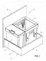
- Fig. 1 1 shows a pull-out part 1, which in a known manner comprises a front part 2, side walls 3 serving as lateral delimitations and a bottom 4, and which is likewise equipped in a known manner with guide means, not shown, by means of which it can be inserted into and pulled out of a cupboard element ,
- the front part 2 covers in a known manner from the opening of the cabinet element, when the pull-out 1 is in the inserted into the cabinet element position.
- Other elements may be used, such as strips of guide means or other webs.
- Between the front part 2 and the side walls 3 1 container 5, 6 are placed on the bottom 4 of the pull-out, which, as will be described below, are fixed to the ground to slipping when inserting the pull-1 in the cabinet element or when pulling out to avoid from the cabinet element.
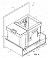
- Fig. 2 again shows the pull-out 1 with the front part 2, the side walls 3 and the bottom 4.
- an element 7 is placed on the bottom 4 of the pull-out part 1, which is formed from a resting on the bottom 4 foot part 8 and connected to the foot part 8 standing part 9.
- the standing part 9 is the foot part 8 at an angle, for example, at right angles aligned.
- the foot part 8 of the element 7 consists of two tabs 10.
- a mat 11 is placed on the foot part 8 of the element 7, a mat 11 is placed. This mat 11 is provided with recesses 12 through which the two tabs 10, which form the foot part 8 of the element 7, protrude.
- the mat 11 with the inserted element 7 is placed on the bottom 4 of the Ausdorfeils 1, the mat 11 thus covers the bottom 4 of the Ausdorfeils 1 as well as the two tabs 10, which form the foot part 8 of the element 7, the standing part 9 of Elements 7 protrudes beyond the mat 11.
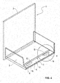
- the mat 11 has a size which corresponds to the inner surface of the bottom 4 of the pull-out part 1, the edges of the mat 11 thus abut against the side walls 3 forming the lateral delimitations and the front part 2 of the pull-out part 1.
- the mat 11 is thus held undamaged in the pull-out part 1, whereby the element 7 held by the mat 11 is fixed non-slidably to the bottom 4 of the pull-out part 1.
- the element 7 is at the bottom 4 of the extension part 1 in the correct position.
- the container 5, 6 On the lying on the bottom 4 of the pull-out part 1 mat 11, the container 5, 6 can be made.
- the mat 11 is formed from a plastic, preferably from a high-quality polystyrene rubber.
- a plastic preferably from a high-quality polystyrene rubber.
- Such mats can be obtained, for example, from Agoform GmbH, 32584 Löhne, Germany, under the name "anti-slip mats", which are suitable as inserts, in particular for pull-out parts for cupboard elements in kitchens.
- Such mats are flexible, but they still have the required rigidity to provide the desired fixation function for the elements 7 can.
- the inserted mat 11 has a certain thickness, for example about 1 mm. So that the foot part 8 and the standing part 9 of the element 7 optimally fit into the corresponding recess 12 in the mat 11, the connection between the foot part 8 and the standing part 9 of the element 7 is designed as a web 13. This creates between the mat 11 facing surface of the foot part 8 and the lower edge of the standing part 9, a gap, which provides space for the mat 11 so that it can spread optimally.
- the size of the recesses 12 in the mat 11 is selected so that the recesses 12 surround the webs 13 rich, so that an optimal fixation and the exact positioning of the elements 7 can be achieved.
- Fig. 7 again shows a pull-out 1, as he too Fig. 1
- side walls 3 and bottom 4 again containers 1 5, 6 and 14 are used, which, as will be described below, are fixed to the bottom to prevent slippage during insertion of the pull-out 1 in the cabinet element or to avoid when pulling out of the cabinet element.
- the standing part 9 of the element 7 is formed by two brackets 15, between which a carrier 16 can be used, to which different containers 5, 6 and 14 can be hung.
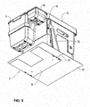
- Fig. 8 shows the element 7, which in turn has a foot part 8 and a standing part 9, which standing part 9, as already mentioned, is formed by two opposite brackets 15. Between these two brackets 15, a carrier 16 can be hung, to which the containers 5, 6 and 14 can be hung.
- a mat 11 can be placed, as previously described.
- This mat 11 is provided with two recesses 12, through which the two brackets 15, which form the standing part 9 of the element 7, protrude.
- One of the recesses 12 is attached to the edge of the mat 11, the other recess 12 is mounted within the mat 11.
- the mat can be inserted into the bracket 15 of the stationary part 9 of the element 7, the mounted inside the mat 11 recess 12 must be connected to the edge of the mat 11 with an auxiliary slot 17, especially if the head portion of the bracket 15 has larger dimensions , as the foot region of the bracket 15, which is enclosed by the recess 12 of the mat 11.
- Fig. 9 shows the bottom of the mat 11, which is placed on the foot part 8 of the element 7.
- auxiliary slot 17 can be seen, which is required on the mat 11 for insertion of the corresponding bracket 15 in the mat.
- the containers 5, 6 and 14 are mounted on the two brackets 15 connecting carrier 16, the containers 5, 6 and 14 are mounted.
- Fig. 10 shows the arrangement according to Fig. 9 in a view from above, with the mat 11, which is placed on the foot part 8 of the element 7.
- the auxiliary slot, which is mounted in the mat 11, can also be seen.
- the arrangement, as in the Fig. 9 and 10 can be shown in the pull-out 1 on the floor 4 ( Fig. 7 ) be inserted.
- the mat 11 has a size such that it comes to rest on the front part 2 and the side walls 4. As a result, the mat 11 can not slip inside the pull-out part 1, and the element 7 and thus the containers 5, 6 and 14 held in the element 7 are positioned and fixed in the pull-out part 1.
- the carrier 16 may be provided with means 18, in which the containers 5, 6 and 14 can be hung.
- the elements 7 may be formed from sheets, wherein the shape of the elements 7 can be obtained in a known manner by punching and bending operations. Of course, other known and suitable materials are conceivable, which can be brought in known and suitable operations in the desired shape.
Abstract
Description
- Die vorliegende Erfindung bezieht sich auf ein Ausziehteil für ein Schrankelement, welches in das Schrankelement einschiebbar und aus diesem ausziehbar ist, welches einen Boden und seitliche Abgrenzungen aufweist, auf welchen Boden Elemente aufsetzbar sind, die über Fixiermittel am Boden fixiert sind, welche Elemente einen auf dem Boden aufliegenden Fussteil und mindestens einen mit dem Fussteil verbundenen stehenden Teil aufweisen, welcher stehende Teil zur Aufnahme von Behältern oder dergleichen und/oder zur Unterteilung des Bodens dient.
- Ausziehteile, die schubladenartig in Schrankelemente eingesetzt werden und somit in die Schrankelemente einschiebbar und aus diesen ausziehbar sind, sind in vielfältiger Weise bekannt. Auf den Boden dieser Ausziehteile können verschiedene Elemente aufgesetzt werden, beispielsweise Halterungen für Behälter wie Kehrichtbehälter, Behälter für die Aufnahme von Grünabfällen und weitere Behälter zum Sammeln oder Unterbringen von weiteren Utensilien, oder beispielsweise den Boden unterteilende Wände oder Begrenzungsleisten.
- Um zu vermeiden, dass diese auf den Boden des Ausziehteils aufgesetzten Elemente beim Ausziehen des Ausziehteils aus dem Schrankelement oder beim Einschieben in das Schrankelement verrutschen können, müssen diese am Boden fixiert werden, was üblicherweise durch Verschraubung erfolgt. Eine derartige Verschraubung ist einerseits aber aufwändig, andererseits entstehen dadurch im Boden des Ausziehteils Schraubenlöcher. Zudem müssen die Elemente bei der Fixierung am Boden des Ausziehteils genau positioniert werden, was durch eine genaue Vermassung oder durch zusätzliche Schablonen erreichbar ist, was einen zusätzlichen Aufwand zur Folge hat. Eine Fixierung der Elemente kann auch durch Verklebung erreicht werden, auch hier ist aber eine genaue Positionierung erforderlich.
- Die Aufgabe der vorliegenden Erfindung besteht somit darin, die Fixiermittel zum Fixieren der auf den Boden eines Ausziehteils aufgesetzten Elemente so zu gestalten, dass der Aufwand zum Anbringen dieser Fixiermittel möglichst einfach wird und dass am Ausziehteil keine Anpassungen wie das Anbringen von Schraubenlöchern oder dergleichen vorgenommen werden müssen. Zudem sollen die Elemente ohne zusätzlichen Aufwand richtig positioniert sein.
- Erfindungsgemäss erfolgt die Lösung dieser Aufgabe dadurch, dass die Fixiermittel aus einer Matte bestehen, welche auf den Boden des Schrankelements und auf die Fussteile der Elemente auflegbar ist, welche Matte mit Ausnehmungen versehen ist, durch welche die stehenden Teile der Elemente hindurchragen.
- In einer derartigen Matte können an den entsprechenden Stellen in einfacher Weise die Ausnehmungen angebracht werden, beispielsweise durch Ausstanzen, auf die Elemente, die auf den Boden des Ausziehteils aufgelegt sind, kann dann die Matte aufgesetzt werden, derart, dass die stehenden Teile der Elemente durch die Ausnehmungen hindurchragen. Die Matte, die durch die seitlichen Abgrenzungen des Bodens gehalten ist, fixiert somit die Elemente in der gewünschten Position am Boden des Ausziehteils. Die genaue Positionierung dieser Elemente kann somit ohne Vermassung des Bodens und ohne zusätzliche Schablone erreicht werden. Zusätzlich wird der Boden durch diese aufgelegte Matte noch geschützt und verbessert zudem die ästhetische Wirkung.
- In vorteilhafter Weise ist die Matte aus einem Kunststoff gebildet und ist biegsam und längs- und querstabil. Dadurch werden die Elemente in optimaler Weise am Boden des Ausziehteils in Position gehalten. Durch die Biegsamkeit der Matte wird eine einfache Handhabung erreicht.
- In vorteilhafter Weise ist der Kunststoff, aus welchem die Matte gebildet ist, ein hochwertiger Polystyrolkautschuk, der die gewünschten Eigenschaften aufweist.
- In vorteilhafter Weise sind die Verbindungen zwischen Fussteil und stehendem Teil durch Stege gebildet, welche in die Ausnehmungen der Matte zu stehen kommen.
- In vorteilhafter Weise umschliessen die Ausnehmungen in der Matte die Stege, wodurch eine optimale Fixierung erreicht wird.
- In vorteilhafter Weise sind in der Matte Hilfsschlitze angebracht, durch welche das Einsetzen der Elemente in die Matte ausführbar ist. Dadurch wird das Aufsetzen der Matte auf die Elemente vereinfacht.
- Eine weitere vorteilhafte Ausgestaltung der Erfindung besteht darin, dass die Elemente aus Blechen gebildet sind, was eine kostengünstige Herstellung ermöglicht.
- In vorteilhafter Weise ist die Form der Elemente aus Blech durch Stanz- und Biegevorgänge erreichbar, wodurch ein einfacher Herstellvorgang erreicht werden kann.
- In vorteilhafter Weise ist jeweils der stehende Teil des Elements mit Mitteln für die Aufnahme von Behältern ausgestattet. Dadurch können diese in einfacher und optimaler Weise in die Elemente eingesetzt werden.
- Ausführungsformen der Erfindung werden nachfolgend anhand der beiliegenden Zeichnung beispielhaft näher erläutert.
- Es zeigt
-
Fig. 1 in räumlicher Darstellung eine erste Ausführungsform eines Ausziehteil mit eingesetzten Behältern; -
Fig. 2 in räumlicher und auseinander gezogener Darstellung den Ausziehteil, ein Element, die Matte und die in den Ausziehteil einsetzbaren Behälter gemässFig. 1 ; -
Fig. 3 in räumlicher und zum Teil geschnittener Darstellung den Ausziehteil mit eingesetztem Element, Matte und Behältern gemässFig. 2 ; -
Fig.4 in räumlicher und zum Teil geschnittener Darstellung den Ausziehteil mit eingesetztem Element und Matte gemässFig. 2 ; -
Fig. 5 in vergrösserter räumlicher Darstellung einen Bodenbereich des Ausziehteils mit eingesetztem Element und Matte gemässFig. 4 ; -
Fig. 6 eine Schnittdarstellung des Ausziehteils gemässFig. 3 ; -
Fig. 6a eine Vergrösserung eines Bereichs der Schnittdarstellung gemässFig. 6 ; -
Fig. 7 in räumlicher Darstellung eine zweite Ausführungsform eines Ausziehteil mit eingesetzten Behältern; -
Fig. 8 in räumlicher und auseinandergezogener Darstellung ein Element, die Matte und die in den Ausziehteil einsetzbaren Behälter gemässFig. 7 ; -
Fig. 9 eine Ansicht von unten auf eine räumliche Darstellung der Matte, des Elementes und der Behälter gemässFig. 7 ; und -
Fig. 10 in räumlicher Darstellung die Matte, das Element und einen Teil der Behälter gemässFig. 7 . -
Fig. 1 zeigt einen Ausziehteil 1, der in bekannter Weise einen Frontteil 2, als seitliche Abgrenzungen dienende Seitenwände 3 und einen Boden 4 umfasst, und welcher ebenfalls in bekannter Weise mit nicht dargestellten Führungsmitteln ausgestattet ist, mittels welchen er in ein Schrankelement einschiebbar und aus diesem ausziehbar ist. Hierbei deckt der Frontteil 2 in bekannter Weise die Öffnung des Schrankelementes ab, wenn sich der Ausziehteil 1 in der in das Schrankelement eingeschobenen Position befindet. Als seitliche Abgrenzungen können anstelle von Seitenwänden 3 auch andere Elemente eingesetzt sein, beispielsweise Leisten von Führungsmittel oder andere Stege. Zwischen den Frontteil 2 und die Seitenwände 3 sind auf den Boden 4 des Ausziehteiles 1 Behälter 5, 6 aufgesetzt, welche, wie nachfolgend noch beschrieben wird, am Boden fixiert sind, um ein Verrutschen beim Einschieben des Ausziehteils 1 in das Schrankelement bzw. beim Ausziehen aus dem Schrankelement zu vermeiden. -
Fig. 2 zeigt wiederum das Ausziehteil 1 mit dem Frontteil 2, den Seitenwänden 3 und dem Boden 4. Wie dies insbesondere auch in denFig. 3 undFig. 4 ersichtlich ist, wird auf den Boden 4 des Ausziehteils 1 ein Element 7 aufgesetzt, das aus einem auf dem Boden 4 aufliegenden Fussteil 8 und einem mit dem Fussteil 8 verbundenen stehenden Teil 9 gebildet ist. Der stehende Teil 9 ist zum Fussteil 8 winklig, beispielsweise rechtwinklig, ausgerichtet. Im hier dargestellten Ausführungsbeispiel besteht der Fussteil 8 des Elements 7 aus zwei Laschen 10. Auf den Fussteil 8 des Elements 7 wird eine Matte 11 aufgelegt. Diese Matte 11 ist mit Ausnehmungen 12 ausgestattet, durch welche die beiden Laschen 10, die den Fussteil 8 des Elementes 7 bilden, hindurchragen. Die Matte 11 mit dem eingesetzten Element 7 wird auf den Boden 4 des Ausziehteils 1 aufgelegt, die Matte 11 bedeckt somit den Boden 4 des Ausziehteils 1 wie auch die beiden Laschen 10, die den Fussteil 8 des Elements 7 bilden, der stehende Teil 9 des Elements 7 steht über die Matte 11 vor. - Die Matte 11 weist eine Grösse auf, die der Innenfläche des Bodens 4 des Ausziehteils 1 entspricht, die Ränder der Matte 11 liegen somit an den die seitlichen Abgrenzungen bildenden Seitenwänden 3 und dem Frontteil 2 des Ausziehteils 1 an. Die Matte11 ist somit unverrutschbar im Ausziehteil 1 gehalten, wodurch auch das durch die Matte 11 gehaltene Element 7 unverrutschbar am Boden 4 des Ausziehteils 1 fixiert ist. Gleichzeitig befindet sich das Element 7 am Boden 4 des Ausziehteils 1 in der korrekten Position.
- Auf die auf dem Boden 4 des Ausziehteils 1 liegende Matte 11 können die Behälter 5, 6 gestellt werden. Das eingesetzte Element 7 bildet für die Behälter 5, 6 einen Anschlag, die Behälter 5, 6 werden somit zwischen dem Frontteil 2, den beiden einander gegenüberliegenden Seitenwänden 3 und dem Element 7 in einer festen Position gehalten.
- Die Matte 11 ist aus einem Kunststoff gebildet, vorzugsweise aus einem hochwertigen Polystyrolkautschuk. Derartige Matten können beispielsweise bei der Firma Agoform GmbH, 32584 Löhne, Deutschland, unter der Bezeichnung "Antirutschmatten" bezogen werden, die als Einlagen insbesondere für Ausziehteile für Schrankelemente in Küchen geeignet sind. Derartige Matten sind biegsam, sie weisen aber trotzdem die erforderliche Steifigkeit auf, um die gewünschte Fixierfunktion für die Elemente 7 bieten zu können.
- Wie aus
Fig. 5 entnehmbar ist, weist die eingesetzte Matte 11 eine gewisse Dicke auf, z.B. etwa 1 mm. Damit der Fussteil 8 und der stehende Teil 9 des Elementes 7 in optimaler Weise in die entsprechende Ausnehmung 12 in der Matte 11 passt, ist die Verbindung zwischen dem Fussteil 8 und dem stehenden Teil 9 des Elementes 7 als Steg 13 ausgebildet. Dadurch entsteht zwischen der der Matte 11 zugewandten Oberfläche des Fussteils 8 und der Unterkante des stehenden Teils 9 ein Zwischenraum, welcher Platz bietet für die Matte 11, so dass diese sich optimal ausbreiten kann. Die Grösse der Ausnehmungen 12 in der Matte 11 ist so gewählt, dass die Ausnehmungen 12 die Stege 13 satt umschliessen, so dass eine optimale Fixierung und die genaue Positionierung der Elemente 7 erreicht werden kann. - Aus den Schnittdarstellungen der
Fig. 6 und Fig. 6a ist wiederum ersichtlich, wie das Element 7 mit Fussteil 8 und stehendem Teil 9 durch die Matte 11 am Boden 4 des Ausziehteils 1 gehalten und fixiert wird, so dass der eingesetzte Behälter 5 in der entsprechenden Position im Ausziehteil 1 gehalten ist. -
Fig. 7 zeigt wiederum einen Ausziehteil 1, wie er zuFig. 1 beschrieben worden ist, mit Frontteil 2, Seitenwänden 3 und Boden 4. Wiederum sind in den Ausziehteil 1 Behälter 5, 6 und 14 eingesetzt, welche, wie nachfolgend noch beschrieben wird, am Boden fixiert sind, um ein Verrutschen beim Einschieben des Ausziehteils 1 in das Schrankelement bzw. beim Ausziehen aus dem Schrankelement zu vermeiden. Der stehende Teil 9 des Elements 7 ist durch zwei Bügel 15 gebildet, zwischen welche ein Träger 16 eingesetzt werden kann, an welchem unterschiedliche Behälter 5, 6 und 14 eingehängt werden können. -
Fig. 8 zeigt das Element 7, das wiederum einen Fussteil 8 und einen stehenden Teil 9 aufweist, welcher stehende Teil 9, wie bereits erwähnt, durch zwei einander gegenüberliegende Bügel 15 gebildet ist. Zwischen diese beiden Bügel 15 kann ein Träger 16 eingehängt werden, an welchem die Behälter 5, 6 und 14 eingehängt werden können. - Auf den Fussteil 8 des Elements 7 kann wiederum eine Matte 11 aufgelegt werden, wie sie vorgängig schon beschrieben worden ist. Diese Matte 11 ist mit zwei Ausnehmungen 12 versehen, durch welche die beiden Bügel 15, die den stehenden Teil 9 des Elements 7 bilden, hindurchragen. Eine der Ausnehmungen 12 ist am Rand der Matte 11 angebracht, die andere Ausnehmung 12 ist innerhalb der Matte 11 angebracht. Damit die Matte in die Bügel 15 des stehenden Teils 9 des Elements 7 eingelegt werden kann, muss die innerhalb der Matte 11 angebrachte Ausnehmung 12 mit dem Rand der Matte 11 mit einem Hilfsschlitz 17 verbunden werden, insbesondere wenn der Kopfbereich des Bügels 15 grössere Abmessungen aufweist, als der Fussbereich des Bügels 15, welcher von der Ausnehmung 12 der Matte 11 umschlossen wird.
-
Fig. 9 zeigt die Unterseite der Matte 11, welche auf den Fussteil 8 des Elements 7 aufgelegt ist. Zudem ist der an der Matte 11 angebrachte Hilfsschlitz 17 ersichtlich, der an der Matte 11 zum Einführen des entsprechenden Bügels 15 in die Matte erforderlich ist. Auf den die beiden Bügel 15 verbindenden Träger 16 sind die Behälter 5, 6 und 14 eingehängt. -
Fig. 10 zeigt die Anordnung gemässFig. 9 in einer Ansicht von oben, mit der Matte 11, welche auf den Fussteil 8 des Elements 7 aufgelegt ist. Die beiden Bügel 15, welche den stehenden Teil 9 des Elements 7 bilden, ragen durch die beiden in der Matte 11 angebrachten Ausnehmungen 12. Zudem ist auch der Hilfsschlitz ersichtlich, welcher in der Matte 11 angebracht ist. - Die Anordnung, wie sie in den
Fig. 9 und10 dargestellt ist, kann in den Ausziehteil 1 auf den Boden 4 (Fig. 7 ) eingelegt werden. Die Matte 11 weist eine derartige Grösse auf, dass sie am Frontteil 2 und den Seitenwänden 4 zur Anlage kommt. Dadurch kann die Matte 11 innerhalb des Ausziehteils 1 nicht verrutschen, das Element 7 und somit die im Element 7 gehaltenen Behälter 5, 6 und 14 sind im Ausziehteil 1 positioniert und fixiert. - Wie aus der
Fig. 10 ersichtlich ist, kann der Träger 16 mit Mitteln 18 versehen sein, in welche die Behälter 5, 6 und 14 eingehängt werden können. - Die Elemente 7 können aus Blechen gebildet sein, wobei die Form der Elemente 7 in bekannter Weise durch Stanz- und Biegevorgänge erhalten werden kann. Selbstverständlich sind aber auch andere bekannte und geeignete Materialien denkbar, die in bekannten und geeigneten Arbeitsgängen in die gewünschte Form gebracht werden können.
- Selbstverständlich können auch Elemente eingesetzt werden, die andere geeignete Funktionen erfüllen können, als sie vorgängig beschrieben worden sind.
- Mit dieser erfindungsgemässen Lösung können in einfacher Weise Elemente, die unterschiedlichste Funktionen ausüben können, in Ausziehteilen am Boden positioniert und fixiert werden, ohne dass am Boden beispielsweise Schraubenlöcher angebracht werden müssen.
Claims (9)
- Ausziehteil (1) für ein Schrankelement, welches in das Schrankelement einschiebbar und aus diesem ausziehbar ist, welches einen Boden (4) und seitliche Abgrenzungen (3) aufweist, auf welchen Boden (4) Elemente (7) aufsetzbar sind, die über Fixiermittel am Boden (4) fixiert sind, welche Elemente (7) einen auf dem Boden (4) aufliegenden Fussteil (8) und mindestens einen mit dem Fussteil (8) verbundenen stehenden Teil (9) aufweisen, welcher stehende Teil (9) zur Aufnahme von Behältern (5, 6) oder dergleichen und/oder zur Unterteilung des Bodens (4) dient, dadurch gekennzeichnet, dass die Fixiermittel aus einer Matte (11) bestehen, welche auf den Boden (4) des Schrankelements und auf die Fussteile (8) der Elemente (7) auflegbar ist, welche Matte (11) mit Ausnehmungen (12) versehen ist, durch welche die stehenden Teile (9) der Elemente (7) hindurchragen.
- Ausziehteil (1) für ein Schrankelement nach Anspruch 1, dadurch gekennzeichnet, dass die Matte (11) aus einem Kunststoff gebildet ist und biegsam und längs- und querstabil ist.
- Ausziehteil (1) für ein Schrankelement nach Anspruch 2, dadurch gekennzeichnet, dass der Kunststoff, aus welchem die Matte (11) gebildet ist, ein hochwertiger Polystyrolkautschuk ist.
- Ausziehteil (1) für ein Schrankelement nach einem der Ansprüche 1 bis 3, dadurch gekennzeichnet, dass die Verbindung zwischen Fussteil (8) und stehendem Teil (9) durch Stege (13) gebildet sind.
- Ausziehteil (1) für ein Schrankelement nach Anspruch 4, dadurch gekennzeichnet, dass die Ausnehmungen (12) in der Matte (11) die Stege (13) umschliessen.
- Ausziehteil (1) für ein Schrankelement nach einem der Ansprüche 1 bis 5, dadurch gekennzeichnet, dass in der Matte (11) Hilfsschlitze (17) angebracht sind, durch welche das Einsetzen der Elemente (7) in die Matte (11) ausführbar ist.
- Ausziehteil (1) für ein Schrankelement nach einem der Ansprüche 1 bis 6, dadurch gekennzeichnet, dass die Elemente (7) aus Blechen gebildet sind.
- Ausziehteil (1) für ein Schrankelement nach Anspruch 7, dadurch gekennzeichnet, dass die Form der Elemente (7) aus Blech durch Stanz- und Biegevorgänge erreichbar ist.
- Ausziehteil (1) für ein Schrankelement nach einem der Ansprüche 1 bis 8, dadurch gekennzeichnet, dass jeweils der stehende Teil (9) des Elements (7) mit Mitteln (18) für die Aufnahme von Behältern ausgestattet ist.
Priority Applications (3)
| Application Number | Priority Date | Filing Date | Title |
|---|---|---|---|
| ES15165752.5T ES2685902T3 (es) | 2015-04-29 | 2015-04-29 | Parte extraíble para un elemento de armario |
| PL15165752T PL3087867T3 (pl) | 2015-04-29 | 2015-04-29 | Część wysuwana elementu szafy |
| EP15165752.5A EP3087867B1 (de) | 2015-04-29 | 2015-04-29 | Ausziehteil für ein schrankelement |
Applications Claiming Priority (1)
| Application Number | Priority Date | Filing Date | Title |
|---|---|---|---|
| EP15165752.5A EP3087867B1 (de) | 2015-04-29 | 2015-04-29 | Ausziehteil für ein schrankelement |
Publications (2)
| Publication Number | Publication Date |
|---|---|
| EP3087867A1 true EP3087867A1 (de) | 2016-11-02 |
| EP3087867B1 EP3087867B1 (de) | 2018-06-13 |
Family
ID=53015681
Family Applications (1)
| Application Number | Title | Priority Date | Filing Date |
|---|---|---|---|
| EP15165752.5A Active EP3087867B1 (de) | 2015-04-29 | 2015-04-29 | Ausziehteil für ein schrankelement |
Country Status (3)
| Country | Link |
|---|---|
| EP (1) | EP3087867B1 (de) |
| ES (1) | ES2685902T3 (de) |
| PL (1) | PL3087867T3 (de) |
Cited By (4)
| Publication number | Priority date | Publication date | Assignee | Title |
|---|---|---|---|---|
| EP3447006A1 (de) * | 2017-08-25 | 2019-02-27 | A. & J. Stöckli AG | Behälterkombination mit einem erstbehälter, einem kleinbehälter und einem adapterbehälter |
| EP3446594A1 (de) * | 2017-08-25 | 2019-02-27 | A. & J. Stöckli AG | Behältervorrichtung mit einem behälter und einer festhaltevorrichtung |
| WO2020015850A1 (de) * | 2018-07-17 | 2020-01-23 | Lichterberg Handels- Und Werbeagentur Ug | Möbel mit kaschiertem unterteil |
| US20210219721A1 (en) * | 2020-01-17 | 2021-07-22 | Peka-Metall Ag | Cabinet pull-out for a cabinet element |
Citations (3)
| Publication number | Priority date | Publication date | Assignee | Title |
|---|---|---|---|---|
| US1979578A (en) * | 1933-04-15 | 1934-11-06 | Simmons Kate | Protective mat for drawers |
| DE102005018033A1 (de) * | 2005-04-18 | 2006-10-19 | Laschet, Michael, Dipl.-Ing. | Variables Schubkasteneinsatzsystem |
| WO2007031097A1 (de) * | 2005-09-09 | 2007-03-22 | Hueser Eckhart | System und verfahren zum bilden von unterteilungen an ablageflächen |
-
2015
- 2015-04-29 ES ES15165752.5T patent/ES2685902T3/es active Active
- 2015-04-29 EP EP15165752.5A patent/EP3087867B1/de active Active
- 2015-04-29 PL PL15165752T patent/PL3087867T3/pl unknown
Patent Citations (3)
| Publication number | Priority date | Publication date | Assignee | Title |
|---|---|---|---|---|
| US1979578A (en) * | 1933-04-15 | 1934-11-06 | Simmons Kate | Protective mat for drawers |
| DE102005018033A1 (de) * | 2005-04-18 | 2006-10-19 | Laschet, Michael, Dipl.-Ing. | Variables Schubkasteneinsatzsystem |
| WO2007031097A1 (de) * | 2005-09-09 | 2007-03-22 | Hueser Eckhart | System und verfahren zum bilden von unterteilungen an ablageflächen |
Cited By (6)
| Publication number | Priority date | Publication date | Assignee | Title |
|---|---|---|---|---|
| EP3447006A1 (de) * | 2017-08-25 | 2019-02-27 | A. & J. Stöckli AG | Behälterkombination mit einem erstbehälter, einem kleinbehälter und einem adapterbehälter |
| EP3446594A1 (de) * | 2017-08-25 | 2019-02-27 | A. & J. Stöckli AG | Behältervorrichtung mit einem behälter und einer festhaltevorrichtung |
| WO2020015850A1 (de) * | 2018-07-17 | 2020-01-23 | Lichterberg Handels- Und Werbeagentur Ug | Möbel mit kaschiertem unterteil |
| US20210219721A1 (en) * | 2020-01-17 | 2021-07-22 | Peka-Metall Ag | Cabinet pull-out for a cabinet element |
| US11533995B2 (en) * | 2020-01-17 | 2022-12-27 | Peka-Metall Ag | Cabinet pull-out for a cabinet element |
| US11717084B2 (en) | 2020-01-17 | 2023-08-08 | Peka-Metall Ag | Cabinet pull-out for a cabinet element |
Also Published As
| Publication number | Publication date |
|---|---|
| EP3087867B1 (de) | 2018-06-13 |
| ES2685902T3 (es) | 2018-10-15 |
| PL3087867T3 (pl) | 2018-09-28 |
Similar Documents
| Publication | Publication Date | Title |
|---|---|---|
| DE102018101210B4 (de) | Wandbefestigung für eine elektronische Anzeige, Computeranordnung und Verfahren zur Montage einer elektronischen Anzeige und eines Computersystems an einer Wand | |
| DE2605876C2 (de) | Ablagevorrichtung zum Zusammenhalten von gelochtem Blattmaterial | |
| DE102008019416A1 (de) | Beschlagaufbau und Verfahren zur lagerichtigen Montage einer Dekorplatte an einer Tür eines Haushaltsgeräts | |
| EP3087867B1 (de) | Ausziehteil für ein schrankelement | |
| DE202013101469U1 (de) | Duschtür-Baugruppe | |
| DE102008019421A1 (de) | Beschlagaufbau und Verfahren zur höhenrichtigen Montage einer Dekorplatte an einer Tür eines Haushaltsgeräts | |
| EP1956940B1 (de) | Vorrichtung zum verdecken eines spalts | |
| DE202015001489U1 (de) | Vorrichtung zur lösbaren Verbindung eines in einem Möbelkorpus über eine Führungseinheit beweglich geführten Möbelauszugs mit der Führungseinheit | |
| DE2819138C2 (de) | Vorrichtung zum verstellbaren Befestigen eines Gegenstandes an einer Wand | |
| DE202014004012U1 (de) | Möbelteil-Abdeckelement | |
| DE202014105081U1 (de) | Becherhalter | |
| EP2943092B1 (de) | Montageelement für ein auszugsystem und verfahren zum montieren eines auszugsystems | |
| DE102017124413A1 (de) | Bohrschablone und Verfahren zum Markieren oder Anbohren zweier Möbelplatten | |
| DE664346C (de) | Verschiebungssichere Spannhakenbefestigung von aus Flachteilen aufgebauten Rahmen fuer Drehkondensatoren oder aehnliche Geraete an Werkplatten | |
| DE102008019415A1 (de) | Beschlagaufbau und Verfahren zur höhenrichtigen Montage einer Dekorplatte an einer Tür eines Haushaltsgeräts | |
| DE202008005406U1 (de) | Beschlagaufbau zur höhenrichtigen Montage einer Dekorplatte an einer Tür eines Haushaltsgeräts | |
| DE202011050020U1 (de) | Vorrichtung zur Befestigung eines Kraftfahrzeug-Kennzeichens | |
| DE2721326B2 (de) | Haushaltgerät, z.B. Geschirrspülmaschine mit einem frontseitigen Sockelrücksprung | |
| DE102007051924B4 (de) | Halte-Vorrichtung | |
| DE202007008666U1 (de) | Kunststoffkoffer, insbesondere Werkzeugkoffer aus Kunststoff | |
| DE202014104926U1 (de) | Wandbauteil, Schublade mit einem solchen Wandbauteil und Möbel | |
| DE202014008298U1 (de) | Montagevorrichtung für Blendenelemente | |
| DE10239692B4 (de) | Verfahren zum Bestimmen von Befestigungspunkten sowie eine Vorrichtung zur Durchführung des Verfahrens | |
| DE102013103258A1 (de) | Verbindungsbausatz für aufeinandersetzbare Wäschebehandlungsgeräte | |
| DE102014116102A1 (de) | Zementkasten für ein Gerät |
Legal Events
| Date | Code | Title | Description |
|---|---|---|---|
| PUAI | Public reference made under article 153(3) epc to a published international application that has entered the european phase |
Free format text: ORIGINAL CODE: 0009012 |
|
| AK | Designated contracting states |
Kind code of ref document: A1 Designated state(s): AL AT BE BG CH CY CZ DE DK EE ES FI FR GB GR HR HU IE IS IT LI LT LU LV MC MK MT NL NO PL PT RO RS SE SI SK SM TR |
|
| AX | Request for extension of the european patent |
Extension state: BA ME |
|
| STAA | Information on the status of an ep patent application or granted ep patent |
Free format text: STATUS: REQUEST FOR EXAMINATION WAS MADE |
|
| RBV | Designated contracting states (corrected) |
Designated state(s): AL AT BE BG CH CY CZ DE DK EE ES FI FR GB GR HR HU IE IS IT LI LT LU LV MC MK MT NL NO PL PT RO RS SE SI SK SM TR |
|
| 17P | Request for examination filed |
Effective date: 20170501 |
|
| STAA | Information on the status of an ep patent application or granted ep patent |
Free format text: STATUS: EXAMINATION IS IN PROGRESS |
|
| 17Q | First examination report despatched |
Effective date: 20170921 |
|
| GRAP | Despatch of communication of intention to grant a patent |
Free format text: ORIGINAL CODE: EPIDOSNIGR1 |
|
| STAA | Information on the status of an ep patent application or granted ep patent |
Free format text: STATUS: GRANT OF PATENT IS INTENDED |
|
| RIC1 | Information provided on ipc code assigned before grant |
Ipc: A47B 88/919 20170101ALI20180208BHEP Ipc: A47B 57/58 20060101AFI20180208BHEP Ipc: A47B 77/18 20060101ALI20180208BHEP Ipc: B65F 1/14 20060101ALI20180208BHEP Ipc: A47B 96/04 20060101ALI20180208BHEP Ipc: A47B 97/00 20060101ALI20180208BHEP |
|
| INTG | Intention to grant announced |
Effective date: 20180227 |
|
| GRAS | Grant fee paid |
Free format text: ORIGINAL CODE: EPIDOSNIGR3 |
|
| GRAA | (expected) grant |
Free format text: ORIGINAL CODE: 0009210 |
|
| STAA | Information on the status of an ep patent application or granted ep patent |
Free format text: STATUS: THE PATENT HAS BEEN GRANTED |
|
| AK | Designated contracting states |
Kind code of ref document: B1 Designated state(s): AL AT BE BG CH CY CZ DE DK EE ES FI FR GB GR HR HU IE IS IT LI LT LU LV MC MK MT NL NO PL PT RO RS SE SI SK SM TR |
|
| REG | Reference to a national code |
Ref country code: GB Ref legal event code: FG4D Free format text: NOT ENGLISH |
|
| REG | Reference to a national code |
Ref country code: CH Ref legal event code: EP Ref country code: CH Ref legal event code: NV Representative=s name: BOVARD AG PATENT- UND MARKENANWAELTE, CH Ref country code: AT Ref legal event code: REF Ref document number: 1007570 Country of ref document: AT Kind code of ref document: T Effective date: 20180615 |
|
| REG | Reference to a national code |
Ref country code: IE Ref legal event code: FG4D Free format text: LANGUAGE OF EP DOCUMENT: GERMAN |
|
| REG | Reference to a national code |
Ref country code: DE Ref legal event code: R096 Ref document number: 502015004628 Country of ref document: DE |
|
| REG | Reference to a national code |
Ref country code: ES Ref legal event code: FG2A Ref document number: 2685902 Country of ref document: ES Kind code of ref document: T3 Effective date: 20181015 |
|
| REG | Reference to a national code |
Ref country code: NL Ref legal event code: MP Effective date: 20180613 |
|
| REG | Reference to a national code |
Ref country code: LT Ref legal event code: MG4D |
|
| PG25 | Lapsed in a contracting state [announced via postgrant information from national office to epo] |
Ref country code: BG Free format text: LAPSE BECAUSE OF FAILURE TO SUBMIT A TRANSLATION OF THE DESCRIPTION OR TO PAY THE FEE WITHIN THE PRESCRIBED TIME-LIMIT Effective date: 20180913 Ref country code: LT Free format text: LAPSE BECAUSE OF FAILURE TO SUBMIT A TRANSLATION OF THE DESCRIPTION OR TO PAY THE FEE WITHIN THE PRESCRIBED TIME-LIMIT Effective date: 20180613 Ref country code: CY Free format text: LAPSE BECAUSE OF FAILURE TO SUBMIT A TRANSLATION OF THE DESCRIPTION OR TO PAY THE FEE WITHIN THE PRESCRIBED TIME-LIMIT Effective date: 20180613 Ref country code: NO Free format text: LAPSE BECAUSE OF FAILURE TO SUBMIT A TRANSLATION OF THE DESCRIPTION OR TO PAY THE FEE WITHIN THE PRESCRIBED TIME-LIMIT Effective date: 20180913 Ref country code: FI Free format text: LAPSE BECAUSE OF FAILURE TO SUBMIT A TRANSLATION OF THE DESCRIPTION OR TO PAY THE FEE WITHIN THE PRESCRIBED TIME-LIMIT Effective date: 20180613 Ref country code: SE Free format text: LAPSE BECAUSE OF FAILURE TO SUBMIT A TRANSLATION OF THE DESCRIPTION OR TO PAY THE FEE WITHIN THE PRESCRIBED TIME-LIMIT Effective date: 20180613 |
|
| PG25 | Lapsed in a contracting state [announced via postgrant information from national office to epo] |
Ref country code: RS Free format text: LAPSE BECAUSE OF FAILURE TO SUBMIT A TRANSLATION OF THE DESCRIPTION OR TO PAY THE FEE WITHIN THE PRESCRIBED TIME-LIMIT Effective date: 20180613 Ref country code: LV Free format text: LAPSE BECAUSE OF FAILURE TO SUBMIT A TRANSLATION OF THE DESCRIPTION OR TO PAY THE FEE WITHIN THE PRESCRIBED TIME-LIMIT Effective date: 20180613 Ref country code: HR Free format text: LAPSE BECAUSE OF FAILURE TO SUBMIT A TRANSLATION OF THE DESCRIPTION OR TO PAY THE FEE WITHIN THE PRESCRIBED TIME-LIMIT Effective date: 20180613 Ref country code: GR Free format text: LAPSE BECAUSE OF FAILURE TO SUBMIT A TRANSLATION OF THE DESCRIPTION OR TO PAY THE FEE WITHIN THE PRESCRIBED TIME-LIMIT Effective date: 20180914 |
|
| PG25 | Lapsed in a contracting state [announced via postgrant information from national office to epo] |
Ref country code: NL Free format text: LAPSE BECAUSE OF FAILURE TO SUBMIT A TRANSLATION OF THE DESCRIPTION OR TO PAY THE FEE WITHIN THE PRESCRIBED TIME-LIMIT Effective date: 20180613 |
|
| PG25 | Lapsed in a contracting state [announced via postgrant information from national office to epo] |
Ref country code: SK Free format text: LAPSE BECAUSE OF FAILURE TO SUBMIT A TRANSLATION OF THE DESCRIPTION OR TO PAY THE FEE WITHIN THE PRESCRIBED TIME-LIMIT Effective date: 20180613 Ref country code: CZ Free format text: LAPSE BECAUSE OF FAILURE TO SUBMIT A TRANSLATION OF THE DESCRIPTION OR TO PAY THE FEE WITHIN THE PRESCRIBED TIME-LIMIT Effective date: 20180613 Ref country code: RO Free format text: LAPSE BECAUSE OF FAILURE TO SUBMIT A TRANSLATION OF THE DESCRIPTION OR TO PAY THE FEE WITHIN THE PRESCRIBED TIME-LIMIT Effective date: 20180613 Ref country code: IS Free format text: LAPSE BECAUSE OF FAILURE TO SUBMIT A TRANSLATION OF THE DESCRIPTION OR TO PAY THE FEE WITHIN THE PRESCRIBED TIME-LIMIT Effective date: 20181013 Ref country code: EE Free format text: LAPSE BECAUSE OF FAILURE TO SUBMIT A TRANSLATION OF THE DESCRIPTION OR TO PAY THE FEE WITHIN THE PRESCRIBED TIME-LIMIT Effective date: 20180613 |
|
| REG | Reference to a national code |
Ref country code: CH Ref legal event code: PK Free format text: BERICHTIGUNGEN |
|
| RIC2 | Information provided on ipc code assigned after grant |
Ipc: B65F 1/14 20060101ALI20180208BHEP Ipc: A47B 77/18 20060101ALI20180208BHEP Ipc: A47B 88/919 20170101ALI20180208BHEP Ipc: A47B 96/04 20060101ALI20180208BHEP Ipc: A47B 97/00 20060101ALI20180208BHEP Ipc: A47B 57/58 20060101AFI20180208BHEP |
|
| PG25 | Lapsed in a contracting state [announced via postgrant information from national office to epo] |
Ref country code: SM Free format text: LAPSE BECAUSE OF FAILURE TO SUBMIT A TRANSLATION OF THE DESCRIPTION OR TO PAY THE FEE WITHIN THE PRESCRIBED TIME-LIMIT Effective date: 20180613 Ref country code: IT Free format text: LAPSE BECAUSE OF FAILURE TO SUBMIT A TRANSLATION OF THE DESCRIPTION OR TO PAY THE FEE WITHIN THE PRESCRIBED TIME-LIMIT Effective date: 20180613 |
|
| REG | Reference to a national code |
Ref country code: DE Ref legal event code: R097 Ref document number: 502015004628 Country of ref document: DE |
|
| PLBE | No opposition filed within time limit |
Free format text: ORIGINAL CODE: 0009261 |
|
| STAA | Information on the status of an ep patent application or granted ep patent |
Free format text: STATUS: NO OPPOSITION FILED WITHIN TIME LIMIT |
|
| 26N | No opposition filed |
Effective date: 20190314 |
|
| PG25 | Lapsed in a contracting state [announced via postgrant information from national office to epo] |
Ref country code: SI Free format text: LAPSE BECAUSE OF FAILURE TO SUBMIT A TRANSLATION OF THE DESCRIPTION OR TO PAY THE FEE WITHIN THE PRESCRIBED TIME-LIMIT Effective date: 20180613 Ref country code: DK Free format text: LAPSE BECAUSE OF FAILURE TO SUBMIT A TRANSLATION OF THE DESCRIPTION OR TO PAY THE FEE WITHIN THE PRESCRIBED TIME-LIMIT Effective date: 20180613 |
|
| PG25 | Lapsed in a contracting state [announced via postgrant information from national office to epo] |
Ref country code: AL Free format text: LAPSE BECAUSE OF FAILURE TO SUBMIT A TRANSLATION OF THE DESCRIPTION OR TO PAY THE FEE WITHIN THE PRESCRIBED TIME-LIMIT Effective date: 20180613 |
|
| REG | Reference to a national code |
Ref country code: BE Ref legal event code: MM Effective date: 20190430 |
|
| PG25 | Lapsed in a contracting state [announced via postgrant information from national office to epo] |
Ref country code: LU Free format text: LAPSE BECAUSE OF NON-PAYMENT OF DUE FEES Effective date: 20190429 Ref country code: MC Free format text: LAPSE BECAUSE OF FAILURE TO SUBMIT A TRANSLATION OF THE DESCRIPTION OR TO PAY THE FEE WITHIN THE PRESCRIBED TIME-LIMIT Effective date: 20180613 |
|
| PG25 | Lapsed in a contracting state [announced via postgrant information from national office to epo] |
Ref country code: BE Free format text: LAPSE BECAUSE OF NON-PAYMENT OF DUE FEES Effective date: 20190430 |
|
| PG25 | Lapsed in a contracting state [announced via postgrant information from national office to epo] |
Ref country code: TR Free format text: LAPSE BECAUSE OF FAILURE TO SUBMIT A TRANSLATION OF THE DESCRIPTION OR TO PAY THE FEE WITHIN THE PRESCRIBED TIME-LIMIT Effective date: 20180613 |
|
| PG25 | Lapsed in a contracting state [announced via postgrant information from national office to epo] |
Ref country code: IE Free format text: LAPSE BECAUSE OF NON-PAYMENT OF DUE FEES Effective date: 20190429 |
|
| PG25 | Lapsed in a contracting state [announced via postgrant information from national office to epo] |
Ref country code: PT Free format text: LAPSE BECAUSE OF FAILURE TO SUBMIT A TRANSLATION OF THE DESCRIPTION OR TO PAY THE FEE WITHIN THE PRESCRIBED TIME-LIMIT Effective date: 20181015 |
|
| PG25 | Lapsed in a contracting state [announced via postgrant information from national office to epo] |
Ref country code: MT Free format text: LAPSE BECAUSE OF FAILURE TO SUBMIT A TRANSLATION OF THE DESCRIPTION OR TO PAY THE FEE WITHIN THE PRESCRIBED TIME-LIMIT Effective date: 20180613 Ref country code: HU Free format text: LAPSE BECAUSE OF FAILURE TO SUBMIT A TRANSLATION OF THE DESCRIPTION OR TO PAY THE FEE WITHIN THE PRESCRIBED TIME-LIMIT; INVALID AB INITIO Effective date: 20150429 |
|
| PG25 | Lapsed in a contracting state [announced via postgrant information from national office to epo] |
Ref country code: MK Free format text: LAPSE BECAUSE OF FAILURE TO SUBMIT A TRANSLATION OF THE DESCRIPTION OR TO PAY THE FEE WITHIN THE PRESCRIBED TIME-LIMIT Effective date: 20180613 |
|
| PGFP | Annual fee paid to national office [announced via postgrant information from national office to epo] |
Ref country code: GB Payment date: 20220425 Year of fee payment: 8 Ref country code: FR Payment date: 20220421 Year of fee payment: 8 Ref country code: ES Payment date: 20220629 Year of fee payment: 8 Ref country code: DE Payment date: 20220420 Year of fee payment: 8 |
|
| PGFP | Annual fee paid to national office [announced via postgrant information from national office to epo] |
Ref country code: PL Payment date: 20220425 Year of fee payment: 8 Ref country code: AT Payment date: 20220421 Year of fee payment: 8 |
|
| PGFP | Annual fee paid to national office [announced via postgrant information from national office to epo] |
Ref country code: CH Payment date: 20230502 Year of fee payment: 9 |
|
| REG | Reference to a national code |
Ref country code: DE Ref legal event code: R119 Ref document number: 502015004628 Country of ref document: DE |
|
| REG | Reference to a national code |
Ref country code: AT Ref legal event code: MM01 Ref document number: 1007570 Country of ref document: AT Kind code of ref document: T Effective date: 20230429 |
|
| GBPC | Gb: european patent ceased through non-payment of renewal fee |
Effective date: 20230429 |
|
| PG25 | Lapsed in a contracting state [announced via postgrant information from national office to epo] |
Ref country code: GB Free format text: LAPSE BECAUSE OF NON-PAYMENT OF DUE FEES Effective date: 20230429 |
|
| PG25 | Lapsed in a contracting state [announced via postgrant information from national office to epo] |
Ref country code: GB Free format text: LAPSE BECAUSE OF NON-PAYMENT OF DUE FEES Effective date: 20230429 Ref country code: FR Free format text: LAPSE BECAUSE OF NON-PAYMENT OF DUE FEES Effective date: 20230430 Ref country code: DE Free format text: LAPSE BECAUSE OF NON-PAYMENT OF DUE FEES Effective date: 20231103 Ref country code: AT Free format text: LAPSE BECAUSE OF NON-PAYMENT OF DUE FEES Effective date: 20230429 |