EP3086972B1 - Fahrzeug mit einem elektrischen generatorsatz - Google Patents
Fahrzeug mit einem elektrischen generatorsatz Download PDFInfo
- Publication number
- EP3086972B1 EP3086972B1 EP14835482.2A EP14835482A EP3086972B1 EP 3086972 B1 EP3086972 B1 EP 3086972B1 EP 14835482 A EP14835482 A EP 14835482A EP 3086972 B1 EP3086972 B1 EP 3086972B1
- Authority
- EP
- European Patent Office
- Prior art keywords
- vehicle
- battery
- auxiliary connector
- distribution device
- connector
- Prior art date
- Legal status (The legal status is an assumption and is not a legal conclusion. Google has not performed a legal analysis and makes no representation as to the accuracy of the status listed.)
- Not-in-force
Links
Images

Classifications
-
- B—PERFORMING OPERATIONS; TRANSPORTING
- B60—VEHICLES IN GENERAL
- B60K—ARRANGEMENT OR MOUNTING OF PROPULSION UNITS OR OF TRANSMISSIONS IN VEHICLES; ARRANGEMENT OR MOUNTING OF PLURAL DIVERSE PRIME-MOVERS IN VEHICLES; AUXILIARY DRIVES FOR VEHICLES; INSTRUMENTATION OR DASHBOARDS FOR VEHICLES; ARRANGEMENTS IN CONNECTION WITH COOLING, AIR INTAKE, GAS EXHAUST OR FUEL SUPPLY OF PROPULSION UNITS IN VEHICLES
- B60K6/00—Arrangement or mounting of plural diverse prime-movers for mutual or common propulsion, e.g. hybrid propulsion systems comprising electric motors and internal combustion engines
- B60K6/20—Arrangement or mounting of plural diverse prime-movers for mutual or common propulsion, e.g. hybrid propulsion systems comprising electric motors and internal combustion engines the prime-movers consisting of electric motors and internal combustion engines, e.g. HEVs
- B60K6/42—Arrangement or mounting of plural diverse prime-movers for mutual or common propulsion, e.g. hybrid propulsion systems comprising electric motors and internal combustion engines the prime-movers consisting of electric motors and internal combustion engines, e.g. HEVs characterised by the architecture of the hybrid electric vehicle
- B60K6/46—Series type
-
- B—PERFORMING OPERATIONS; TRANSPORTING
- B60—VEHICLES IN GENERAL
- B60K—ARRANGEMENT OR MOUNTING OF PROPULSION UNITS OR OF TRANSMISSIONS IN VEHICLES; ARRANGEMENT OR MOUNTING OF PLURAL DIVERSE PRIME-MOVERS IN VEHICLES; AUXILIARY DRIVES FOR VEHICLES; INSTRUMENTATION OR DASHBOARDS FOR VEHICLES; ARRANGEMENTS IN CONNECTION WITH COOLING, AIR INTAKE, GAS EXHAUST OR FUEL SUPPLY OF PROPULSION UNITS IN VEHICLES
- B60K15/00—Arrangement in connection with fuel supply of combustion engines or other fuel consuming energy converters, e.g. fuel cells; Mounting or construction of fuel tanks
- B60K15/03—Fuel tanks
- B60K15/063—Arrangement of tanks
- B60K15/067—Mounting of tanks
- B60K15/07—Mounting of tanks of gas tanks
-
- B—PERFORMING OPERATIONS; TRANSPORTING
- B60—VEHICLES IN GENERAL
- B60L—PROPULSION OF ELECTRICALLY-PROPELLED VEHICLES; SUPPLYING ELECTRIC POWER FOR AUXILIARY EQUIPMENT OF ELECTRICALLY-PROPELLED VEHICLES; ELECTRODYNAMIC BRAKE SYSTEMS FOR VEHICLES IN GENERAL; MAGNETIC SUSPENSION OR LEVITATION FOR VEHICLES; MONITORING OPERATING VARIABLES OF ELECTRICALLY-PROPELLED VEHICLES; ELECTRIC SAFETY DEVICES FOR ELECTRICALLY-PROPELLED VEHICLES
- B60L1/00—Supplying electric power to auxiliary equipment of vehicles
- B60L1/006—Supplying electric power to auxiliary equipment of vehicles to power outlets
-
- B—PERFORMING OPERATIONS; TRANSPORTING
- B60—VEHICLES IN GENERAL
- B60L—PROPULSION OF ELECTRICALLY-PROPELLED VEHICLES; SUPPLYING ELECTRIC POWER FOR AUXILIARY EQUIPMENT OF ELECTRICALLY-PROPELLED VEHICLES; ELECTRODYNAMIC BRAKE SYSTEMS FOR VEHICLES IN GENERAL; MAGNETIC SUSPENSION OR LEVITATION FOR VEHICLES; MONITORING OPERATING VARIABLES OF ELECTRICALLY-PROPELLED VEHICLES; ELECTRIC SAFETY DEVICES FOR ELECTRICALLY-PROPELLED VEHICLES
- B60L3/00—Electric devices on electrically-propelled vehicles for safety purposes; Monitoring operating variables, e.g. speed, deceleration or energy consumption
- B60L3/0023—Detecting, eliminating, remedying or compensating for drive train abnormalities, e.g. failures within the drive train
- B60L3/0046—Detecting, eliminating, remedying or compensating for drive train abnormalities, e.g. failures within the drive train relating to electric energy storage systems, e.g. batteries or capacitors
-
- B—PERFORMING OPERATIONS; TRANSPORTING
- B60—VEHICLES IN GENERAL
- B60L—PROPULSION OF ELECTRICALLY-PROPELLED VEHICLES; SUPPLYING ELECTRIC POWER FOR AUXILIARY EQUIPMENT OF ELECTRICALLY-PROPELLED VEHICLES; ELECTRODYNAMIC BRAKE SYSTEMS FOR VEHICLES IN GENERAL; MAGNETIC SUSPENSION OR LEVITATION FOR VEHICLES; MONITORING OPERATING VARIABLES OF ELECTRICALLY-PROPELLED VEHICLES; ELECTRIC SAFETY DEVICES FOR ELECTRICALLY-PROPELLED VEHICLES
- B60L3/00—Electric devices on electrically-propelled vehicles for safety purposes; Monitoring operating variables, e.g. speed, deceleration or energy consumption
- B60L3/0023—Detecting, eliminating, remedying or compensating for drive train abnormalities, e.g. failures within the drive train
- B60L3/0061—Detecting, eliminating, remedying or compensating for drive train abnormalities, e.g. failures within the drive train relating to electrical machines
-
- B—PERFORMING OPERATIONS; TRANSPORTING
- B60—VEHICLES IN GENERAL
- B60L—PROPULSION OF ELECTRICALLY-PROPELLED VEHICLES; SUPPLYING ELECTRIC POWER FOR AUXILIARY EQUIPMENT OF ELECTRICALLY-PROPELLED VEHICLES; ELECTRODYNAMIC BRAKE SYSTEMS FOR VEHICLES IN GENERAL; MAGNETIC SUSPENSION OR LEVITATION FOR VEHICLES; MONITORING OPERATING VARIABLES OF ELECTRICALLY-PROPELLED VEHICLES; ELECTRIC SAFETY DEVICES FOR ELECTRICALLY-PROPELLED VEHICLES
- B60L50/00—Electric propulsion with power supplied within the vehicle
- B60L50/50—Electric propulsion with power supplied within the vehicle using propulsion power supplied by batteries or fuel cells
- B60L50/60—Electric propulsion with power supplied within the vehicle using propulsion power supplied by batteries or fuel cells using power supplied by batteries
- B60L50/61—Electric propulsion with power supplied within the vehicle using propulsion power supplied by batteries or fuel cells using power supplied by batteries by batteries charged by engine-driven generators, e.g. series hybrid electric vehicles
-
- B—PERFORMING OPERATIONS; TRANSPORTING
- B60—VEHICLES IN GENERAL
- B60L—PROPULSION OF ELECTRICALLY-PROPELLED VEHICLES; SUPPLYING ELECTRIC POWER FOR AUXILIARY EQUIPMENT OF ELECTRICALLY-PROPELLED VEHICLES; ELECTRODYNAMIC BRAKE SYSTEMS FOR VEHICLES IN GENERAL; MAGNETIC SUSPENSION OR LEVITATION FOR VEHICLES; MONITORING OPERATING VARIABLES OF ELECTRICALLY-PROPELLED VEHICLES; ELECTRIC SAFETY DEVICES FOR ELECTRICALLY-PROPELLED VEHICLES
- B60L58/00—Methods or circuit arrangements for monitoring or controlling batteries or fuel cells, specially adapted for electric vehicles
- B60L58/10—Methods or circuit arrangements for monitoring or controlling batteries or fuel cells, specially adapted for electric vehicles for monitoring or controlling batteries
- B60L58/12—Methods or circuit arrangements for monitoring or controlling batteries or fuel cells, specially adapted for electric vehicles for monitoring or controlling batteries responding to state of charge [SoC]
- B60L58/14—Preventing excessive discharging
-
- B—PERFORMING OPERATIONS; TRANSPORTING
- B60—VEHICLES IN GENERAL
- B60L—PROPULSION OF ELECTRICALLY-PROPELLED VEHICLES; SUPPLYING ELECTRIC POWER FOR AUXILIARY EQUIPMENT OF ELECTRICALLY-PROPELLED VEHICLES; ELECTRODYNAMIC BRAKE SYSTEMS FOR VEHICLES IN GENERAL; MAGNETIC SUSPENSION OR LEVITATION FOR VEHICLES; MONITORING OPERATING VARIABLES OF ELECTRICALLY-PROPELLED VEHICLES; ELECTRIC SAFETY DEVICES FOR ELECTRICALLY-PROPELLED VEHICLES
- B60L58/00—Methods or circuit arrangements for monitoring or controlling batteries or fuel cells, specially adapted for electric vehicles
- B60L58/40—Methods or circuit arrangements for monitoring or controlling batteries or fuel cells, specially adapted for electric vehicles for controlling a combination of batteries and fuel cells
-
- B—PERFORMING OPERATIONS; TRANSPORTING
- B60—VEHICLES IN GENERAL
- B60W—CONJOINT CONTROL OF VEHICLE SUB-UNITS OF DIFFERENT TYPE OR DIFFERENT FUNCTION; CONTROL SYSTEMS SPECIALLY ADAPTED FOR HYBRID VEHICLES; ROAD VEHICLE DRIVE CONTROL SYSTEMS FOR PURPOSES NOT RELATED TO THE CONTROL OF A PARTICULAR SUB-UNIT
- B60W10/00—Conjoint control of vehicle sub-units of different type or different function
- B60W10/04—Conjoint control of vehicle sub-units of different type or different function including control of propulsion units
- B60W10/06—Conjoint control of vehicle sub-units of different type or different function including control of propulsion units including control of combustion engines
-
- B—PERFORMING OPERATIONS; TRANSPORTING
- B60—VEHICLES IN GENERAL
- B60W—CONJOINT CONTROL OF VEHICLE SUB-UNITS OF DIFFERENT TYPE OR DIFFERENT FUNCTION; CONTROL SYSTEMS SPECIALLY ADAPTED FOR HYBRID VEHICLES; ROAD VEHICLE DRIVE CONTROL SYSTEMS FOR PURPOSES NOT RELATED TO THE CONTROL OF A PARTICULAR SUB-UNIT
- B60W10/00—Conjoint control of vehicle sub-units of different type or different function
- B60W10/04—Conjoint control of vehicle sub-units of different type or different function including control of propulsion units
- B60W10/08—Conjoint control of vehicle sub-units of different type or different function including control of propulsion units including control of electric propulsion units, e.g. motors or generators
-
- B—PERFORMING OPERATIONS; TRANSPORTING
- B60—VEHICLES IN GENERAL
- B60W—CONJOINT CONTROL OF VEHICLE SUB-UNITS OF DIFFERENT TYPE OR DIFFERENT FUNCTION; CONTROL SYSTEMS SPECIALLY ADAPTED FOR HYBRID VEHICLES; ROAD VEHICLE DRIVE CONTROL SYSTEMS FOR PURPOSES NOT RELATED TO THE CONTROL OF A PARTICULAR SUB-UNIT
- B60W10/00—Conjoint control of vehicle sub-units of different type or different function
- B60W10/24—Conjoint control of vehicle sub-units of different type or different function including control of energy storage means
- B60W10/26—Conjoint control of vehicle sub-units of different type or different function including control of energy storage means for electrical energy, e.g. batteries or capacitors
-
- B—PERFORMING OPERATIONS; TRANSPORTING
- B60—VEHICLES IN GENERAL
- B60W—CONJOINT CONTROL OF VEHICLE SUB-UNITS OF DIFFERENT TYPE OR DIFFERENT FUNCTION; CONTROL SYSTEMS SPECIALLY ADAPTED FOR HYBRID VEHICLES; ROAD VEHICLE DRIVE CONTROL SYSTEMS FOR PURPOSES NOT RELATED TO THE CONTROL OF A PARTICULAR SUB-UNIT
- B60W10/00—Conjoint control of vehicle sub-units of different type or different function
- B60W10/30—Conjoint control of vehicle sub-units of different type or different function including control of auxiliary equipment, e.g. air-conditioning compressors or oil pumps
-
- B—PERFORMING OPERATIONS; TRANSPORTING
- B60—VEHICLES IN GENERAL
- B60W—CONJOINT CONTROL OF VEHICLE SUB-UNITS OF DIFFERENT TYPE OR DIFFERENT FUNCTION; CONTROL SYSTEMS SPECIALLY ADAPTED FOR HYBRID VEHICLES; ROAD VEHICLE DRIVE CONTROL SYSTEMS FOR PURPOSES NOT RELATED TO THE CONTROL OF A PARTICULAR SUB-UNIT
- B60W30/00—Purposes of road vehicle drive control systems not related to the control of a particular sub-unit, e.g. of systems using conjoint control of vehicle sub-units
- B60W30/18—Propelling the vehicle
- B60W30/18009—Propelling the vehicle related to particular drive situations
-
- B—PERFORMING OPERATIONS; TRANSPORTING
- B60—VEHICLES IN GENERAL
- B60K—ARRANGEMENT OR MOUNTING OF PROPULSION UNITS OR OF TRANSMISSIONS IN VEHICLES; ARRANGEMENT OR MOUNTING OF PLURAL DIVERSE PRIME-MOVERS IN VEHICLES; AUXILIARY DRIVES FOR VEHICLES; INSTRUMENTATION OR DASHBOARDS FOR VEHICLES; ARRANGEMENTS IN CONNECTION WITH COOLING, AIR INTAKE, GAS EXHAUST OR FUEL SUPPLY OF PROPULSION UNITS IN VEHICLES
- B60K1/00—Arrangement or mounting of electrical propulsion units
- B60K2001/001—Arrangement or mounting of electrical propulsion units one motor mounted on a propulsion axle for rotating right and left wheels of this axle
-
- B—PERFORMING OPERATIONS; TRANSPORTING
- B60—VEHICLES IN GENERAL
- B60L—PROPULSION OF ELECTRICALLY-PROPELLED VEHICLES; SUPPLYING ELECTRIC POWER FOR AUXILIARY EQUIPMENT OF ELECTRICALLY-PROPELLED VEHICLES; ELECTRODYNAMIC BRAKE SYSTEMS FOR VEHICLES IN GENERAL; MAGNETIC SUSPENSION OR LEVITATION FOR VEHICLES; MONITORING OPERATING VARIABLES OF ELECTRICALLY-PROPELLED VEHICLES; ELECTRIC SAFETY DEVICES FOR ELECTRICALLY-PROPELLED VEHICLES
- B60L2210/00—Converter types
- B60L2210/40—DC to AC converters
-
- B—PERFORMING OPERATIONS; TRANSPORTING
- B60—VEHICLES IN GENERAL
- B60L—PROPULSION OF ELECTRICALLY-PROPELLED VEHICLES; SUPPLYING ELECTRIC POWER FOR AUXILIARY EQUIPMENT OF ELECTRICALLY-PROPELLED VEHICLES; ELECTRODYNAMIC BRAKE SYSTEMS FOR VEHICLES IN GENERAL; MAGNETIC SUSPENSION OR LEVITATION FOR VEHICLES; MONITORING OPERATING VARIABLES OF ELECTRICALLY-PROPELLED VEHICLES; ELECTRIC SAFETY DEVICES FOR ELECTRICALLY-PROPELLED VEHICLES
- B60L2240/00—Control parameters of input or output; Target parameters
- B60L2240/10—Vehicle control parameters
- B60L2240/12—Speed
-
- B—PERFORMING OPERATIONS; TRANSPORTING
- B60—VEHICLES IN GENERAL
- B60L—PROPULSION OF ELECTRICALLY-PROPELLED VEHICLES; SUPPLYING ELECTRIC POWER FOR AUXILIARY EQUIPMENT OF ELECTRICALLY-PROPELLED VEHICLES; ELECTRODYNAMIC BRAKE SYSTEMS FOR VEHICLES IN GENERAL; MAGNETIC SUSPENSION OR LEVITATION FOR VEHICLES; MONITORING OPERATING VARIABLES OF ELECTRICALLY-PROPELLED VEHICLES; ELECTRIC SAFETY DEVICES FOR ELECTRICALLY-PROPELLED VEHICLES
- B60L2240/00—Control parameters of input or output; Target parameters
- B60L2240/40—Drive Train control parameters
- B60L2240/54—Drive Train control parameters related to batteries
- B60L2240/545—Temperature
-
- B—PERFORMING OPERATIONS; TRANSPORTING
- B60—VEHICLES IN GENERAL
- B60L—PROPULSION OF ELECTRICALLY-PROPELLED VEHICLES; SUPPLYING ELECTRIC POWER FOR AUXILIARY EQUIPMENT OF ELECTRICALLY-PROPELLED VEHICLES; ELECTRODYNAMIC BRAKE SYSTEMS FOR VEHICLES IN GENERAL; MAGNETIC SUSPENSION OR LEVITATION FOR VEHICLES; MONITORING OPERATING VARIABLES OF ELECTRICALLY-PROPELLED VEHICLES; ELECTRIC SAFETY DEVICES FOR ELECTRICALLY-PROPELLED VEHICLES
- B60L2250/00—Driver interactions
- B60L2250/10—Driver interactions by alarm
-
- B—PERFORMING OPERATIONS; TRANSPORTING
- B60—VEHICLES IN GENERAL
- B60L—PROPULSION OF ELECTRICALLY-PROPELLED VEHICLES; SUPPLYING ELECTRIC POWER FOR AUXILIARY EQUIPMENT OF ELECTRICALLY-PROPELLED VEHICLES; ELECTRODYNAMIC BRAKE SYSTEMS FOR VEHICLES IN GENERAL; MAGNETIC SUSPENSION OR LEVITATION FOR VEHICLES; MONITORING OPERATING VARIABLES OF ELECTRICALLY-PROPELLED VEHICLES; ELECTRIC SAFETY DEVICES FOR ELECTRICALLY-PROPELLED VEHICLES
- B60L2250/00—Driver interactions
- B60L2250/16—Driver interactions by display
-
- B—PERFORMING OPERATIONS; TRANSPORTING
- B60—VEHICLES IN GENERAL
- B60Y—INDEXING SCHEME RELATING TO ASPECTS CROSS-CUTTING VEHICLE TECHNOLOGY
- B60Y2400/00—Special features of vehicle units
- B60Y2400/21—External power supplies
- B60Y2400/214—External power supplies by power from domestic supply, e.g. plug in supplies
-
- Y—GENERAL TAGGING OF NEW TECHNOLOGICAL DEVELOPMENTS; GENERAL TAGGING OF CROSS-SECTIONAL TECHNOLOGIES SPANNING OVER SEVERAL SECTIONS OF THE IPC; TECHNICAL SUBJECTS COVERED BY FORMER USPC CROSS-REFERENCE ART COLLECTIONS [XRACs] AND DIGESTS
- Y02—TECHNOLOGIES OR APPLICATIONS FOR MITIGATION OR ADAPTATION AGAINST CLIMATE CHANGE
- Y02T—CLIMATE CHANGE MITIGATION TECHNOLOGIES RELATED TO TRANSPORTATION
- Y02T10/00—Road transport of goods or passengers
- Y02T10/60—Other road transportation technologies with climate change mitigation effect
- Y02T10/62—Hybrid vehicles
-
- Y—GENERAL TAGGING OF NEW TECHNOLOGICAL DEVELOPMENTS; GENERAL TAGGING OF CROSS-SECTIONAL TECHNOLOGIES SPANNING OVER SEVERAL SECTIONS OF THE IPC; TECHNICAL SUBJECTS COVERED BY FORMER USPC CROSS-REFERENCE ART COLLECTIONS [XRACs] AND DIGESTS
- Y02—TECHNOLOGIES OR APPLICATIONS FOR MITIGATION OR ADAPTATION AGAINST CLIMATE CHANGE
- Y02T—CLIMATE CHANGE MITIGATION TECHNOLOGIES RELATED TO TRANSPORTATION
- Y02T10/00—Road transport of goods or passengers
- Y02T10/60—Other road transportation technologies with climate change mitigation effect
- Y02T10/70—Energy storage systems for electromobility, e.g. batteries
-
- Y—GENERAL TAGGING OF NEW TECHNOLOGICAL DEVELOPMENTS; GENERAL TAGGING OF CROSS-SECTIONAL TECHNOLOGIES SPANNING OVER SEVERAL SECTIONS OF THE IPC; TECHNICAL SUBJECTS COVERED BY FORMER USPC CROSS-REFERENCE ART COLLECTIONS [XRACs] AND DIGESTS
- Y02—TECHNOLOGIES OR APPLICATIONS FOR MITIGATION OR ADAPTATION AGAINST CLIMATE CHANGE
- Y02T—CLIMATE CHANGE MITIGATION TECHNOLOGIES RELATED TO TRANSPORTATION
- Y02T10/00—Road transport of goods or passengers
- Y02T10/60—Other road transportation technologies with climate change mitigation effect
- Y02T10/72—Electric energy management in electromobility
Definitions
- the present invention relates to an electric or hybrid vehicle comprising a supply battery for an electric motor for driving the vehicle and optionally a generator set for supplying electric energy by an extension supply.
- Electric vehicles have already been proposed comprising a battery for supplying an electric motor for the motorization of the vehicle.
- the battery is recharged during periods outside of vehicle use, by a recharging connection to an electrical network.
- These vehicles make it possible to control pollution at the vehicle level.
- their autonomy is still relatively modest.
- a hybrid vehicle In order to increase the range of electric vehicles, it has been proposed to construct a hybrid vehicle by equipping an electric vehicle with a range extender which is in practice a generator set supplying a battery recharging current.
- the generator set is composed of a heat engine driving an electric generator.
- the heat engine can run on various fuels, such as gasoline, diesel or gas.
- the document EP-A-0 125 320 describes a hybrid vehicle comprising an electric motor for driving the vehicle, an electric source for supplying the motor with at least one extension power supply, comprising at least one auxiliary connector for supplying an electric component, and a distribution device receiving at least one extension feed.
- the invention aims to provide a hybrid vehicle with a range extender having additional functions.
- the invention relates to an electric or hybrid vehicle comprising an electric motor for driving the vehicle, an electrical source for supplying the motor with at least one extension power supply, the vehicle comprising at least one auxiliary connector. for supplying power to an electrical component, a distribution device receiving at least one extension supply and connection information from the auxiliary connector indicating the presence of the electrical component plugged into the auxiliary connector, the distribution device comprising switching means to then connect the auxiliary connector to at least one of the available extension power supplies.
- the electric power source is chosen from among a battery, a generator set, a recharging connector and are respectively connected to the distribution device by a first extension power supply, a second extension power supply and a third extension power supply.
- the invention it is possible to have at any time thanks to the auxiliary connector, in any place and without connection to the electricity distribution network, an electricity source delivering an electric power capable of supplying an electric device.
- a vehicle is intended in particular for the use of agents who have various needs linked to the use of electrical or portable power equipment in open places, far from an accessible fixed electrical network.
- the use of a generator is particularly advantageous because the same generator can be used on the one hand to extend the autonomy of the electric vehicle and on the other hand to provide electricity for use. external.
- the connection is made, for example, directly between the generator set or the battery and the electrical component.
- the distribution device not only makes it possible to draw electrical energy from the most available source, but also to limit the use of the auxiliary connector to preserve energy reserves.
- the latter when the vehicle is equipped with a generator set, the latter comprises a gas tank for supplying the generator set with energy.
- the combustion of gas is not very polluting, even for a stationary installation.
- the gas tank is removable. It is thus possible to provide a gas recharge quickly.
- the auxiliary connector is accessible from outside the vehicle. It is thus easily accessible for needs outside the vehicle.
- the vehicle comprises a recharging connector for supplying the battery with power from an external current source, the distribution device disconnecting the external current source when the extension power supply to the battery is connected. Priority is given to power from the generator for recharging the battery. Switching takes place automatically as soon as electricity is supplied by the extension supply.
- the distribution device delivers an alternating voltage to the auxiliary connector of between 200V and 240V.
- the distribution device comprises means for regulating the voltage and means for detecting the voltage requirements of the electrical device, the voltage regulating means being arranged to deliver a voltage as a function of the voltage requirements. voltage of the electrical device detected by the detection means. It is thus possible to automatically adapt the voltage delivered as a function of the device connected.
- the auxiliary connector can have several specific plugs adapted to different standards.
- the subject of the invention is also a method for managing energy on a hybrid or electric vehicle comprising an electric motor for driving the vehicle, and at least one electric source from among an electric battery or a generator, characterized in that at least one of the electrical sources is connected to a distribution device by an extension power supply, the distribution device also connecting an extension power supply to an auxiliary connector intended to supply an electrical device when the electrical device is plugged into the connector auxiliary.
- a recharging connector supplies the battery from an external power source, and the distribution device disconnects this source when the extension power supply to the battery is connected.
- the starting of the generating set is controlled when an electrical component is connected to the auxiliary connector, and the stopping of the generating set is controlled when no electrical component is connected to the auxiliary connector and the battery does not request a load. So the generator set only works when necessary.
- the presence of an electrical device can be detected at the level of the auxiliary connector by a return of information to the distribution device.
- it also controls a gas supply to the generator set to supply it with energy synchronously with the starting or stopping of the generator set.
- the control of the gas supply increases the safety of the vehicle.
- the generator set is not started if the pressure in the gas tank is below a predetermined threshold.
- the speed of the vehicle is limited below a predetermined threshold when an electrical device is connected. to the auxiliary connector.
- the speed is limited to limit the risks of the maneuver and also to alert the driver of the connection which is still operational.
- the distribution device comprises calculation means and data storage means, said distribution device being able to limit the use of the auxiliary connector as a function of a preprogrammed mission.
- a mission is defined at least as a function of parameters chosen from: position of the vehicle, distance traveled since the last recharging, battery charge, gas reserve.
- a hybrid vehicle is shown schematically in the figure. figure 1 .
- the hybrid vehicle has four wheels 1, an electric motor 2 for driving the vehicle via two of the wheels 1 and a reduction gear 20, an electric battery 3 to power the motor 2 and a generator 4 to provide power. electrical energy by a first supply of extension 40. It further comprises an instrument panel 5 inside a vehicle cabin and placed in front of the driver and passenger seats.
- the vehicle also carries a gas tank 9 in the form of a bottle provided for supplying the generator set 4.
- the vehicle further comprises a recharging connector 7 for recharging the battery 3 and an auxiliary connector 8 accessible from outside the vehicle for supplying an electrical component A.
- a distribution device 6 is provided to manage interconnections between the devices of the vehicle. .
- the control device 6 is powered by the battery 3 by a second extension power supply 41 and can also be powered directly by the recharging connector 7 by a third extension power supply 42.
- Each of the extension power supplies 40 to 42 makes it possible to offer to the control device 6 of the electric power supply sources for electrically supplying the auxiliary connector 8.
- the extension power supplies 40 to 42 may subsequently be referred to in the text by the term “extension power supply” without reference to their power source electric because their respective roles are identical.
- the battery 3 is connected to a variator 21 to which it supplies a direct voltage.
- the variator supplies motor 2 so that it drives wheels 1 in one direction or the other according to commands from the instrument panel 5.
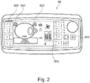
- the instrument panel 5 comprises a display 50, as shown in the figure 2 .
- the display 50 comprises a hybridization status indicator 501, indicating when it is active that the generator set 4 supplies the battery 3, and a status indicator d.
- 'auxiliary 502 which indicates when it is active that an electrical component A is connected to the auxiliary connector 8.
- the instrument panel 5 further comprises a first control button 503 to authorize hybridization, that is to say the supply of battery 3 by the generator 4, and a second control button 504 to authorize the supply of the auxiliary connector 8.
- the display 50 further comprises an indication zone of the charge level 505 of the gas tank 9.
- the display 50 is connected to a control unit 51 of the vehicle, which controls the display 50 and receives information on the state of the vehicle, not detailed here.
- the control unit 51 also communicates with other components of the vehicle via a digital bus, and in particular with the variator 21 and the distribution device 6.
- the device A can typically be a power tool such as a hedge trimmer or a 12V battery charger for recharging batteries.
- the recharging connector 7 is connected to the distribution device 6.
- the distribution device 6 comprises a relay which, on command, connects the recharging connector 7 to the battery 3.
- the relay is supplied by the voltage coming from the extension supply. 40, so that the recharging connector 7 is disconnected when the generator set 4 supplies electricity through the extension supply 40.
- the battery 3 has its own converter 30 to manage the charging of its elements.
- the recharging connector 7 can be connected by the distribution device 6 to the auxiliary connector 8 so that it is thus possible to supply the battery 3 in order to recharge it and to supply power.
- external electrical equipment for example for recharging an electrical device when the battery 3 of the vehicle is charging.
- the distribution device 6 comprises a calculation unit 60 for managing the distribution functions. It also receives the extension power supply 40 from the generator set 4 and connection information 80 from the auxiliary connector 8 indicating the presence of the electrical component A plugged into the auxiliary connector 8.
- the distribution device 6 comprises switching means for connecting the auxiliary connector 8 to the extension power supply 40.
- the auxiliary connector 8 further comprises an indicator 81 indicating the presence of a voltage which supplies the connector 8.
- the gas tank 9 which can be removable is connected to a solenoid valve 91 which makes it possible to connect or not on command a gas network on board the vehicle.
- the gas network then comprises a pressure sensor 92 sending pressure information to the calculation unit 60, then a gas pressure reducer 93 to supply the generator 4.
- the pressure reducer 93 receives a command from the control unit 60. to regulate the gas supply.
- the pressure information is sent over the digital bus for display in the charge level indication area 505.
- the battery 3 When the vehicle is running, without a network power supply connected to the recharging connector 7, the battery 3 provides information on its state of charge on the digital bus and, depending on this level of charge, the computing unit 60 can control the generator 4 so that it supplies energy to the battery 3 via the extension power supply 40. Pressing the second button 504 is received by the computing unit 60 and authorizes the use of the auxiliary connector 8. Auxiliary status indicator 502 remains inactive.
- the computing unit 60 controls the switching means for connecting the auxiliary connector 8 to the extension power supply 40. It also sends information to the display 50 so that the auxiliary status indicator 502 is active. If the generator set 4 is not started, it controls the opening of the solenoid valve 91 to supply the generator set 4 with gas. If the gas pressure is greater than a predetermined threshold, it controls the generator set 4 to obtain its starting beforehand. The generator 4 then supplies energy also to the battery 3, for example in the form of a voltage of 230V in alternating current.
- the connector 8 is supplied with an alternating voltage of between 200V and 240V.
- the distribution device 6 is provided with means for regulating the voltage and with means for detecting the voltage requirements of member A.
- the computing unit 60 can thus control the regulating means for adapt the voltage delivered to the auxiliary connector according to the needs of component A, for example in a voltage range of 6V to 220V, alternating or direct.
- the computing unit 60 When the electrical unit A is disconnected, the computing unit 60 receives the information therefrom. If the battery 3 does not need to be charged any more, the computing unit 60 controls the shutdown of the generator set 4. It also controls the switching means to disconnect the extension power supply 40 and the auxiliary connector 8 It also controls the solenoid valve 91 to cut off the gas supply to the generator 4.
- the battery 3 is supplied by the external source.
- the generator set 4 is running, the external source is disconnected and the battery 3 is supplied by the generator set 4.
- the computing unit 60 When the computing unit 60 receives the information of the presence of an electrical component A connected to the auxiliary connector 8, it sends the vehicle control unit 51 an order to limit the speed of the vehicle below d 'a predetermined threshold. For a land vehicle, this limitation is for example 3 km / h. This limitation order is removed as soon as the electrical component A is disconnected from the auxiliary connector 8.
- the pooling of a generator set is thus achieved in order to extend the autonomy of an electric vehicle and simultaneously to deliver an electric current in order to supply power to portable power tools.
- the generator 4 can receive a speed control. For example, it may have three predetermined speeds, one in reduced mode, providing little power, one in nominal mode, with high power and efficiency, and one in maximum mode, with power at a level higher than the mode. nominal but with an unfavorable return.
- the calculation unit 60 determines and controls the speeds of the generating set 4 as a function of the state of charge of the battery 3, of the demand of the electrical component A and of the engine 2. It takes into account any alarms. from the generator 4 to reduce the speed, for example when a significant heating or another anomaly is detected.
- the invention is not limited to the embodiment which has just been described. It can also be applied to a boat.
- the generator set can be based on a fuel cell.
- the vehicle could be equipped with several auxiliary connectors, outside or inside the vehicle.
- the vehicle according to the invention is an electric vehicle, which does not include a generator.
- the battery 3 is connected to the distribution member 6 by an extension power supply 41.
- the external connector 8 is supplied with power from battery 3 and no longer from generator 4.
- the battery is therefore heavily stressed by the power supply to the vehicle engine and by the external connector.
- the distribution member 6 is therefore designed to limit the use of the external connector according to missions and no longer only according to the gas reserve.
- the operation of the vehicle described above remains the same, except, of course, that the distribution 6 no longer controls the generator set but is designed to control the charge of battery 3.
- a mission is defined as a set of actions to be carried out within a given framework and for a given objective. For example, a mission consists of moving the base to a given point, then performing a task and finally returning to the base. A mission thus includes a distance to be covered on the outward journey, energy consumption, and a return.
- the computer 60 of the distribution member is arranged to calculate and / or store the outward journey, estimate and / or store the return journey and deduce therefrom the quantity of energy necessary to effect this return.
- the distribution member is thus able to limit the energy consumption by the auxiliary connector in order to guarantee the return.
Landscapes
- Engineering & Computer Science (AREA)
- Transportation (AREA)
- Mechanical Engineering (AREA)
- Chemical & Material Sciences (AREA)
- Combustion & Propulsion (AREA)
- Power Engineering (AREA)
- Life Sciences & Earth Sciences (AREA)
- Sustainable Development (AREA)
- Sustainable Energy (AREA)
- Automation & Control Theory (AREA)
- Electric Propulsion And Braking For Vehicles (AREA)
- Hybrid Electric Vehicles (AREA)
Claims (14)
- Elektro- oder Hybridfahrzeug, das einen Elektromotor (2) zum Antreiben des Fahrzeugs, eine Stromquelle (3, 4) zum Versorgen des Motors (2) durch einen Reichweitenverlängerungsversorgung (40, 41, 42) beinhaltet, mindestens einen Hilfsstecker (8) zum Versorgen eines elektrischen Organs (A) beinhaltend, eine Verteilungsvorrichtung (6), die mindestens eine Reichweitenverlängerungsversorgung (40, 41, 42) und eine Verbindungsinformation (80), von dem Hilfsstecker (8) kommend, aufnimmt, die das Vorhandensein des elektrischen Organs (A) anzeigt, das in dem Hilfsstecker (8) angeschlossen ist, wobei die Verteilungsvorrichtung (6) Umschaltmittel zum Verbinden des Hilfssteckers (8) mit mindestens einer der verfügbaren Reichweitenverlängerungsversorgungen (40, 41, 42) beinhaltet, und einen Ladestecker (7) zur Versorgung der Batterie (3) durch eine externe Stromquelle beinhaltet, wobei die Verteilungsvorrichtung (6) die externe Stromquelle trennt, wenn die Reichweitenverlängerungsversorgung (40) der Batterie (3) verbunden ist.
- Hybridfahrzeug nach Anspruch 1, dadurch gekennzeichnet, dass das Fahrzeug mindestens eine Stromversorgungsquelle aus einer Batterie (3), einem Generator (4), einem Ladestecker (7), die jeweils durch eine erste Reichweitenverlängerungsversorgung (40), eine zweite Reichweitenverlängerungsversorgung (41) und eine dritte Reichweitenverlängerungsversorgung (42) mit der Verteilungsvorrichtung (6) verbunden sind.
- Fahrzeug nach Anspruch 1, dadurch gekennzeichnet, dass es einen Gastank (9) beinhaltet, um den Generator (4) mit Energie zu versorgen.
- Fahrzeug nach Anspruch 3, wobei der Gastank (9) abnehmbar ist.
- Fahrzeug nach einem der Ansprüche 1 bis 3, wobei der Hilfsstecker (8) von außerhalb des Fahrzeugs zugänglich ist.
- Fahrzeug nach einem der Ansprüche 1 bis 5, wobei die Verteilungsvorrichtung (6) dem Hilfsstecker (8) eine Wechselspannung liefert, die zwischen 200 V und 240 V enthalten ist.
- Fahrzeug nach einem der Ansprüche 1 bis 5, wobei die Verteilungsvorrichtung Mittel zum Regeln der Spannung und Mittel zum Erkennen des Spannungsbedarfs des elektrischen Organs (A) beinhaltet, wobei die Mittel zum Regeln der Spannung ausgeführt sind, um eine Spannung in Abhängigkeit von dem von den Mitteln zum Erkennen erkannten Spannungsbedarf des elektrischen Organs (A) zu liefern.
- Verfahren für Energiemanagement in einem Hybrid- oder Elektrofahrzeug, das einen Elektromotor (2) zum Antreiben des Fahrzeugs, und mindestens eine Stromquelle aus einer elektrischen Batterie (3), einem Generator (4) beinhaltet, sodass mindestens eine der Stromquellen durch eine Reichweitenverlängerungsversorgung (40, 41, 42) an eine Verteilungsvorrichtung (6) angeschlossen ist, und dadurch, dass ein Ladestecker (7) die Batterie (3) durch eine externe Stromquelle versorgt, wobei die Verteilungsvorrichtung (6) die externe Stromquelle trennt, wenn die Reichweitenverlängerungsversorgung (40) der Batterie (3) verbunden ist, und weiter eine Reichweitenverlängerungsversorgung (40) mit einem Hilfsstecker (8) verbindet, der dazu bestimmt ist, ein elektrisches Organ (A) zu versorgen, wenn das elektrische Organ (A) in dem Hilfsstecker (8) angeschlossen ist.
- Verfahren nach Anspruch 8, wobei das Einschalten des Generators (4) angesteuert wird, wenn ein elektrisches Organ (A) mit dem Hilfsstecker (8) verbunden ist, und der Halt des Generators (4) angesteuert wird, wenn kein elektrisches Organ (A) mit dem Hilfsstecker (8) verbunden ist, und die Batterie (3) keine Ladung anfordert.
- Verfahren nach Anspruch 9, wobei weiter eine Gaszufuhr zum Generator (4) angesteuert wird, um ihn in synchroner Form mit dem Start oder dem Halt des Generators (4) mit Energie zu versorgen.
- Verfahren nach Anspruch 10, wobei der Generator (4) nicht gestartet wird, wenn der Druck in dem Gastank (9) geringer als ein vorbestimmter Schwellenwert ist.
- Verfahren nach einem der Ansprüche 9 bis 11, wobei die Geschwindigkeit des Fahrzeugs unter einem vorbestimmten Schwellenwert begrenzt wird, wenn ein elektrisches Organ (A) mit dem Hilfsstecker (8) verbunden ist.
- Verfahren nach einem der Ansprüche 9 bis 12, wobei die Verteilungsvorrichtung (6) Berechnungsmittel (60) und Datenspeichermittel beinhaltet, wobei die Verteilungsvorrichtung (6) die Verwendung des Hilfssteckers in Abhängigkeit von einer vorprogrammierten Aufgabe begrenzen kann.
- Verfahren nach Anspruch 13, wobei die Aufgabe mindestens in Abhängigkeit von Parametern definiert wird, die ausgewählt sind aus: Position des Fahrzeugs, zurückgelegte Distanz seit der letzten Ladung, Ladung der Batterie, Gasreserve.
Applications Claiming Priority (3)
| Application Number | Priority Date | Filing Date | Title |
|---|---|---|---|
| FR1363478A FR3015378B1 (fr) | 2013-12-23 | 2013-12-23 | Vehicule hybride comportant un groupe electrogene |
| FR1452928A FR3015391B1 (fr) | 2013-12-23 | 2014-04-02 | Vehicule comportant un groupe electrogene |
| PCT/FR2014/053475 WO2015097387A1 (fr) | 2013-12-23 | 2014-12-19 | Véhicule comportant un groupe électrogène |
Publications (2)
| Publication Number | Publication Date |
|---|---|
| EP3086972A1 EP3086972A1 (de) | 2016-11-02 |
| EP3086972B1 true EP3086972B1 (de) | 2021-03-10 |
Family
ID=50231412
Family Applications (1)
| Application Number | Title | Priority Date | Filing Date |
|---|---|---|---|
| EP14835482.2A Not-in-force EP3086972B1 (de) | 2013-12-23 | 2014-12-19 | Fahrzeug mit einem elektrischen generatorsatz |
Country Status (4)
| Country | Link |
|---|---|
| EP (1) | EP3086972B1 (de) |
| FR (2) | FR3015378B1 (de) |
| LT (1) | LT3086972T (de) |
| WO (1) | WO2015097387A1 (de) |
Family Cites Families (6)
| Publication number | Priority date | Publication date | Assignee | Title |
|---|---|---|---|---|
| EP0125320B1 (de) * | 1983-04-14 | 1990-10-03 | Götz Dipl.-Phys. Heidelberg | Verwendung eines Fahrzeugs als Stromerzeugungsaggregat für fahrzeugfremde Stromverbraucher |
| DE10107023A1 (de) * | 2001-02-15 | 2002-08-22 | Volkswagen Ag | Kraftfahrzeug-Energieversorgungseinheit |
| DE10242619A1 (de) * | 2002-09-13 | 2004-03-18 | Still Gmbh | Flurförderzeug |
| DE102007051362A1 (de) * | 2007-10-26 | 2009-04-30 | Enerday Gmbh | Kraftfahrzeug mit Schnittstelle zum Versorgen eines fahrzeugunabhängigen Stromverbrauchers |
| JP4438887B1 (ja) * | 2008-09-26 | 2010-03-24 | トヨタ自動車株式会社 | 電動車両及び電動車両の充電制御方法 |
| DE102012001174B4 (de) * | 2012-01-24 | 2025-06-12 | Volkswagen Aktiengesellschaft | Verfahren zur Steuerung eines Hybridantriebs für ein Fahrzeug und Hybridantrieb |
-
2013
- 2013-12-23 FR FR1363478A patent/FR3015378B1/fr not_active Expired - Fee Related
-
2014
- 2014-04-02 FR FR1452928A patent/FR3015391B1/fr not_active Expired - Fee Related
- 2014-12-19 LT LTEP14835482.2T patent/LT3086972T/lt unknown
- 2014-12-19 WO PCT/FR2014/053475 patent/WO2015097387A1/fr not_active Ceased
- 2014-12-19 EP EP14835482.2A patent/EP3086972B1/de not_active Not-in-force
Non-Patent Citations (1)
| Title |
|---|
| None * |
Also Published As
| Publication number | Publication date |
|---|---|
| FR3015378A1 (fr) | 2015-06-26 |
| WO2015097387A1 (fr) | 2015-07-02 |
| FR3015378B1 (fr) | 2016-02-05 |
| EP3086972A1 (de) | 2016-11-02 |
| FR3015391A1 (fr) | 2015-06-26 |
| FR3015391B1 (fr) | 2016-02-05 |
| LT3086972T (lt) | 2021-07-26 |
Similar Documents
| Publication | Publication Date | Title |
|---|---|---|
| EP2385755B1 (de) | Elektrischer rasenmäher mit fahrer und mit autonom arbeitender stromversorgung | |
| EP2207697B1 (de) | Verfahren zur energieverwaltung in einem kraftfahrzeug | |
| EP2074005B1 (de) | Verfahren zur steuerung von energie in der antriebskette eines hybridfahrzeugs und hybridfahrzeug | |
| EP1410481B1 (de) | Energieverwaltungssystem in einem parallelhybridfahrzeug mit einer haupt- und einer hilfsbatterie | |
| FR3006669A1 (fr) | Dispositif d’alimentation electrique pour aeronef a propulsion electrique | |
| EP2372864B1 (de) | Autonomes Motorisierungssystem | |
| WO2014118476A1 (fr) | Dispositif d'alimentation electrique d'un reseau de bord de vehicule automobile hybride | |
| EP3086972B1 (de) | Fahrzeug mit einem elektrischen generatorsatz | |
| EP4313669A1 (de) | Autonome stromversorgungsvorrichtung, insbesondere zum laden einer batterie | |
| FR2995839A1 (fr) | Systeme de gestion d'un prolongateur d'autonomie d'un vehicule a propulsion electrique | |
| CA3044731A1 (fr) | Procede et systeme de gestion d'un vehicule electrique ou hybride rechargeable | |
| EP2589131B1 (de) | Stromversorgung für ein bordeigenes stromnetz eines kraftfahrzeugs | |
| EP3323668A1 (de) | System und verfahren zur steuerung der unterbrechungsfreien stromversorgung im haushalt, die mit einem elektro- oder hybridfahrzeug verbunden ist | |
| FR2979293A1 (fr) | Dispositif d'alimentation en energie electrique notamment pour un vehicule automobile. | |
| FR3018007A1 (fr) | Dispositif pour vehicule hybride de recharge d'une batterie basse tension a partir du reseau tres basse tension | |
| FR3147152A1 (fr) | Dispositif de gestion d’un module d’extension d’energie pour une batterie de vehicule electrifie | |
| EP3342747B1 (de) | Zuführungsstruktur für gabelstapler | |
| EP4195335A1 (de) | Wärmemanagementsystem für ein brennstoffzellen-sekundärbatterie-hybridsystem | |
| FR2921590A1 (fr) | Dispositif et procede d'alimentation electrique multi-tension pour vehicules hybrides | |
| FR2941066A1 (fr) | Dispositif d'assistance electrique destine a un vehicule hybride | |
| FR3159118A1 (fr) | Procédé de contrôle de puissance d’un réseau haute tension de véhicule électrifié | |
| FR3019395A1 (fr) | Systeme d'alimentation d'une machine electrique de traction d'un vehicule hybride, pour la recharge de sa batterie par un reseau exterieur | |
| FR3147670A1 (fr) | Système d’alimentation électrique de consommateurs d’un véhicule électrique ou hybride et procédé de gestion de l’alimentation d’un tel véhicule | |
| FR3002897A1 (fr) | Dispositif d'alimentation commute pour le reseau de bord d'un vehicule automobile | |
| WO2000032438A1 (fr) | Bloc generateur d'energie intelligent pour maintenir chargees les batteries d'un vehicule electrique |
Legal Events
| Date | Code | Title | Description |
|---|---|---|---|
| PUAI | Public reference made under article 153(3) epc to a published international application that has entered the european phase |
Free format text: ORIGINAL CODE: 0009012 |
|
| 17P | Request for examination filed |
Effective date: 20160701 |
|
| AK | Designated contracting states |
Kind code of ref document: A1 Designated state(s): AL AT BE BG CH CY CZ DE DK EE ES FI FR GB GR HR HU IE IS IT LI LT LU LV MC MK MT NL NO PL PT RO RS SE SI SK SM TR |
|
| AX | Request for extension of the european patent |
Extension state: BA ME |
|
| RAP1 | Party data changed (applicant data changed or rights of an application transferred) |
Owner name: FRANCE CRAFT Owner name: ENGIE |
|
| DAX | Request for extension of the european patent (deleted) | ||
| GRAP | Despatch of communication of intention to grant a patent |
Free format text: ORIGINAL CODE: EPIDOSNIGR1 |
|
| STAA | Information on the status of an ep patent application or granted ep patent |
Free format text: STATUS: GRANT OF PATENT IS INTENDED |
|
| RIC1 | Information provided on ipc code assigned before grant |
Ipc: B60K 15/07 20060101ALI20200904BHEP Ipc: B60K 6/46 20071001AFI20200904BHEP Ipc: B60W 10/18 20120101ALI20200904BHEP Ipc: B60L 1/00 20060101ALI20200904BHEP Ipc: B60W 10/30 20060101ALI20200904BHEP Ipc: B60W 10/08 20060101ALI20200904BHEP Ipc: B60W 10/06 20060101ALI20200904BHEP Ipc: B60W 10/26 20060101ALI20200904BHEP |
|
| INTG | Intention to grant announced |
Effective date: 20200928 |
|
| GRAS | Grant fee paid |
Free format text: ORIGINAL CODE: EPIDOSNIGR3 |
|
| GRAA | (expected) grant |
Free format text: ORIGINAL CODE: 0009210 |
|
| STAA | Information on the status of an ep patent application or granted ep patent |
Free format text: STATUS: THE PATENT HAS BEEN GRANTED |
|
| AK | Designated contracting states |
Kind code of ref document: B1 Designated state(s): AL AT BE BG CH CY CZ DE DK EE ES FI FR GB GR HR HU IE IS IT LI LT LU LV MC MK MT NL NO PL PT RO RS SE SI SK SM TR |
|
| REG | Reference to a national code |
Ref country code: GB Ref legal event code: FG4D Free format text: NOT ENGLISH |
|
| REG | Reference to a national code |
Ref country code: AT Ref legal event code: REF Ref document number: 1369438 Country of ref document: AT Kind code of ref document: T Effective date: 20210315 Ref country code: CH Ref legal event code: EP |
|
| REG | Reference to a national code |
Ref country code: DE Ref legal event code: R096 Ref document number: 602014075626 Country of ref document: DE |
|
| REG | Reference to a national code |
Ref country code: IE Ref legal event code: FG4D Free format text: LANGUAGE OF EP DOCUMENT: FRENCH |
|
| REG | Reference to a national code |
Ref country code: SE Ref legal event code: TRGR |
|
| PG25 | Lapsed in a contracting state [announced via postgrant information from national office to epo] |
Ref country code: FI Free format text: LAPSE BECAUSE OF FAILURE TO SUBMIT A TRANSLATION OF THE DESCRIPTION OR TO PAY THE FEE WITHIN THE PRESCRIBED TIME-LIMIT Effective date: 20210310 Ref country code: HR Free format text: LAPSE BECAUSE OF FAILURE TO SUBMIT A TRANSLATION OF THE DESCRIPTION OR TO PAY THE FEE WITHIN THE PRESCRIBED TIME-LIMIT Effective date: 20210310 Ref country code: GR Free format text: LAPSE BECAUSE OF FAILURE TO SUBMIT A TRANSLATION OF THE DESCRIPTION OR TO PAY THE FEE WITHIN THE PRESCRIBED TIME-LIMIT Effective date: 20210611 Ref country code: BG Free format text: LAPSE BECAUSE OF FAILURE TO SUBMIT A TRANSLATION OF THE DESCRIPTION OR TO PAY THE FEE WITHIN THE PRESCRIBED TIME-LIMIT Effective date: 20210610 |
|
| REG | Reference to a national code |
Ref country code: AT Ref legal event code: MK05 Ref document number: 1369438 Country of ref document: AT Kind code of ref document: T Effective date: 20210310 |
|
| REG | Reference to a national code |
Ref country code: NL Ref legal event code: MP Effective date: 20210310 |
|
| REG | Reference to a national code |
Ref country code: NO Ref legal event code: T2 Effective date: 20210310 |
|
| PG25 | Lapsed in a contracting state [announced via postgrant information from national office to epo] |
Ref country code: RS Free format text: LAPSE BECAUSE OF FAILURE TO SUBMIT A TRANSLATION OF THE DESCRIPTION OR TO PAY THE FEE WITHIN THE PRESCRIBED TIME-LIMIT Effective date: 20210310 |
|
| PG25 | Lapsed in a contracting state [announced via postgrant information from national office to epo] |
Ref country code: NL Free format text: LAPSE BECAUSE OF FAILURE TO SUBMIT A TRANSLATION OF THE DESCRIPTION OR TO PAY THE FEE WITHIN THE PRESCRIBED TIME-LIMIT Effective date: 20210310 |
|
| PG25 | Lapsed in a contracting state [announced via postgrant information from national office to epo] |
Ref country code: SM Free format text: LAPSE BECAUSE OF FAILURE TO SUBMIT A TRANSLATION OF THE DESCRIPTION OR TO PAY THE FEE WITHIN THE PRESCRIBED TIME-LIMIT Effective date: 20210310 Ref country code: AT Free format text: LAPSE BECAUSE OF FAILURE TO SUBMIT A TRANSLATION OF THE DESCRIPTION OR TO PAY THE FEE WITHIN THE PRESCRIBED TIME-LIMIT Effective date: 20210310 Ref country code: EE Free format text: LAPSE BECAUSE OF FAILURE TO SUBMIT A TRANSLATION OF THE DESCRIPTION OR TO PAY THE FEE WITHIN THE PRESCRIBED TIME-LIMIT Effective date: 20210310 Ref country code: CZ Free format text: LAPSE BECAUSE OF FAILURE TO SUBMIT A TRANSLATION OF THE DESCRIPTION OR TO PAY THE FEE WITHIN THE PRESCRIBED TIME-LIMIT Effective date: 20210310 |
|
| PG25 | Lapsed in a contracting state [announced via postgrant information from national office to epo] |
Ref country code: SK Free format text: LAPSE BECAUSE OF FAILURE TO SUBMIT A TRANSLATION OF THE DESCRIPTION OR TO PAY THE FEE WITHIN THE PRESCRIBED TIME-LIMIT Effective date: 20210310 Ref country code: PT Free format text: LAPSE BECAUSE OF FAILURE TO SUBMIT A TRANSLATION OF THE DESCRIPTION OR TO PAY THE FEE WITHIN THE PRESCRIBED TIME-LIMIT Effective date: 20210712 Ref country code: PL Free format text: LAPSE BECAUSE OF FAILURE TO SUBMIT A TRANSLATION OF THE DESCRIPTION OR TO PAY THE FEE WITHIN THE PRESCRIBED TIME-LIMIT Effective date: 20210310 Ref country code: ES Free format text: LAPSE BECAUSE OF FAILURE TO SUBMIT A TRANSLATION OF THE DESCRIPTION OR TO PAY THE FEE WITHIN THE PRESCRIBED TIME-LIMIT Effective date: 20210310 Ref country code: IS Free format text: LAPSE BECAUSE OF FAILURE TO SUBMIT A TRANSLATION OF THE DESCRIPTION OR TO PAY THE FEE WITHIN THE PRESCRIBED TIME-LIMIT Effective date: 20210710 |
|
| REG | Reference to a national code |
Ref country code: DE Ref legal event code: R097 Ref document number: 602014075626 Country of ref document: DE |
|
| PLBE | No opposition filed within time limit |
Free format text: ORIGINAL CODE: 0009261 |
|
| STAA | Information on the status of an ep patent application or granted ep patent |
Free format text: STATUS: NO OPPOSITION FILED WITHIN TIME LIMIT |
|
| PG25 | Lapsed in a contracting state [announced via postgrant information from national office to epo] |
Ref country code: DK Free format text: LAPSE BECAUSE OF FAILURE TO SUBMIT A TRANSLATION OF THE DESCRIPTION OR TO PAY THE FEE WITHIN THE PRESCRIBED TIME-LIMIT Effective date: 20210310 Ref country code: AL Free format text: LAPSE BECAUSE OF FAILURE TO SUBMIT A TRANSLATION OF THE DESCRIPTION OR TO PAY THE FEE WITHIN THE PRESCRIBED TIME-LIMIT Effective date: 20210310 |
|
| PGFP | Annual fee paid to national office [announced via postgrant information from national office to epo] |
Ref country code: LT Payment date: 20211117 Year of fee payment: 8 Ref country code: NO Payment date: 20211118 Year of fee payment: 8 Ref country code: DE Payment date: 20211117 Year of fee payment: 8 Ref country code: RO Payment date: 20211220 Year of fee payment: 8 Ref country code: SE Payment date: 20211119 Year of fee payment: 8 Ref country code: FR Payment date: 20211118 Year of fee payment: 8 |
|
| 26N | No opposition filed |
Effective date: 20211213 |
|
| PG25 | Lapsed in a contracting state [announced via postgrant information from national office to epo] |
Ref country code: SI Free format text: LAPSE BECAUSE OF FAILURE TO SUBMIT A TRANSLATION OF THE DESCRIPTION OR TO PAY THE FEE WITHIN THE PRESCRIBED TIME-LIMIT Effective date: 20210310 |
|
| PGFP | Annual fee paid to national office [announced via postgrant information from national office to epo] |
Ref country code: LV Payment date: 20211117 Year of fee payment: 8 Ref country code: IT Payment date: 20211117 Year of fee payment: 8 |
|
| PG25 | Lapsed in a contracting state [announced via postgrant information from national office to epo] |
Ref country code: IS Free format text: LAPSE BECAUSE OF FAILURE TO SUBMIT A TRANSLATION OF THE DESCRIPTION OR TO PAY THE FEE WITHIN THE PRESCRIBED TIME-LIMIT Effective date: 20210710 |
|
| PG25 | Lapsed in a contracting state [announced via postgrant information from national office to epo] |
Ref country code: MC Free format text: LAPSE BECAUSE OF FAILURE TO SUBMIT A TRANSLATION OF THE DESCRIPTION OR TO PAY THE FEE WITHIN THE PRESCRIBED TIME-LIMIT Effective date: 20210310 |
|
| REG | Reference to a national code |
Ref country code: CH Ref legal event code: PL |
|
| GBPC | Gb: european patent ceased through non-payment of renewal fee |
Effective date: 20211219 |
|
| REG | Reference to a national code |
Ref country code: BE Ref legal event code: MM Effective date: 20211231 |
|
| PG25 | Lapsed in a contracting state [announced via postgrant information from national office to epo] |
Ref country code: LU Free format text: LAPSE BECAUSE OF NON-PAYMENT OF DUE FEES Effective date: 20211219 Ref country code: IE Free format text: LAPSE BECAUSE OF NON-PAYMENT OF DUE FEES Effective date: 20211219 Ref country code: GB Free format text: LAPSE BECAUSE OF NON-PAYMENT OF DUE FEES Effective date: 20211219 |
|
| PG25 | Lapsed in a contracting state [announced via postgrant information from national office to epo] |
Ref country code: BE Free format text: LAPSE BECAUSE OF NON-PAYMENT OF DUE FEES Effective date: 20211231 |
|
| PG25 | Lapsed in a contracting state [announced via postgrant information from national office to epo] |
Ref country code: LI Free format text: LAPSE BECAUSE OF NON-PAYMENT OF DUE FEES Effective date: 20211231 Ref country code: CH Free format text: LAPSE BECAUSE OF NON-PAYMENT OF DUE FEES Effective date: 20211231 |
|
| PG25 | Lapsed in a contracting state [announced via postgrant information from national office to epo] |
Ref country code: HU Free format text: LAPSE BECAUSE OF FAILURE TO SUBMIT A TRANSLATION OF THE DESCRIPTION OR TO PAY THE FEE WITHIN THE PRESCRIBED TIME-LIMIT; INVALID AB INITIO Effective date: 20141219 |
|
| PG25 | Lapsed in a contracting state [announced via postgrant information from national office to epo] |
Ref country code: CY Free format text: LAPSE BECAUSE OF FAILURE TO SUBMIT A TRANSLATION OF THE DESCRIPTION OR TO PAY THE FEE WITHIN THE PRESCRIBED TIME-LIMIT Effective date: 20210310 |
|
| REG | Reference to a national code |
Ref country code: DE Ref legal event code: R119 Ref document number: 602014075626 Country of ref document: DE |
|
| REG | Reference to a national code |
Ref country code: LT Ref legal event code: MM4D Effective date: 20221219 |
|
| REG | Reference to a national code |
Ref country code: NO Ref legal event code: MMEP |
|
| PG25 | Lapsed in a contracting state [announced via postgrant information from national office to epo] |
Ref country code: RO Free format text: LAPSE BECAUSE OF NON-PAYMENT OF DUE FEES Effective date: 20221219 Ref country code: LV Free format text: LAPSE BECAUSE OF NON-PAYMENT OF DUE FEES Effective date: 20221219 |
|
| REG | Reference to a national code |
Ref country code: SE Ref legal event code: EUG |
|
| PG25 | Lapsed in a contracting state [announced via postgrant information from national office to epo] |
Ref country code: SE Free format text: LAPSE BECAUSE OF NON-PAYMENT OF DUE FEES Effective date: 20221220 Ref country code: NO Free format text: LAPSE BECAUSE OF NON-PAYMENT OF DUE FEES Effective date: 20221231 Ref country code: DE Free format text: LAPSE BECAUSE OF NON-PAYMENT OF DUE FEES Effective date: 20230701 |
|
| PG25 | Lapsed in a contracting state [announced via postgrant information from national office to epo] |
Ref country code: LT Free format text: LAPSE BECAUSE OF NON-PAYMENT OF DUE FEES Effective date: 20221219 Ref country code: FR Free format text: LAPSE BECAUSE OF NON-PAYMENT OF DUE FEES Effective date: 20221231 |
|
| PG25 | Lapsed in a contracting state [announced via postgrant information from national office to epo] |
Ref country code: IT Free format text: LAPSE BECAUSE OF NON-PAYMENT OF DUE FEES Effective date: 20221219 |
|
| PG25 | Lapsed in a contracting state [announced via postgrant information from national office to epo] |
Ref country code: MK Free format text: LAPSE BECAUSE OF FAILURE TO SUBMIT A TRANSLATION OF THE DESCRIPTION OR TO PAY THE FEE WITHIN THE PRESCRIBED TIME-LIMIT Effective date: 20210310 |
|
| PG25 | Lapsed in a contracting state [announced via postgrant information from national office to epo] |
Ref country code: TR Free format text: LAPSE BECAUSE OF FAILURE TO SUBMIT A TRANSLATION OF THE DESCRIPTION OR TO PAY THE FEE WITHIN THE PRESCRIBED TIME-LIMIT Effective date: 20210310 |
|
| PG25 | Lapsed in a contracting state [announced via postgrant information from national office to epo] |
Ref country code: MT Free format text: LAPSE BECAUSE OF FAILURE TO SUBMIT A TRANSLATION OF THE DESCRIPTION OR TO PAY THE FEE WITHIN THE PRESCRIBED TIME-LIMIT Effective date: 20210310 |