EP2372864B1 - Autonomes Motorisierungssystem - Google Patents
Autonomes Motorisierungssystem Download PDFInfo
- Publication number
- EP2372864B1 EP2372864B1 EP10305321.1A EP10305321A EP2372864B1 EP 2372864 B1 EP2372864 B1 EP 2372864B1 EP 10305321 A EP10305321 A EP 10305321A EP 2372864 B1 EP2372864 B1 EP 2372864B1
- Authority
- EP
- European Patent Office
- Prior art keywords
- electrically
- type
- accumulators
- power
- self
- Prior art date
- Legal status (The legal status is an assumption and is not a legal conclusion. Google has not performed a legal analysis and makes no representation as to the accuracy of the status listed.)
- Active
Links
Images
Classifications
-
- B—PERFORMING OPERATIONS; TRANSPORTING
- B60—VEHICLES IN GENERAL
- B60L—PROPULSION OF ELECTRICALLY-PROPELLED VEHICLES; SUPPLYING ELECTRIC POWER FOR AUXILIARY EQUIPMENT OF ELECTRICALLY-PROPELLED VEHICLES; ELECTRODYNAMIC BRAKE SYSTEMS FOR VEHICLES IN GENERAL; MAGNETIC SUSPENSION OR LEVITATION FOR VEHICLES; MONITORING OPERATING VARIABLES OF ELECTRICALLY-PROPELLED VEHICLES; ELECTRIC SAFETY DEVICES FOR ELECTRICALLY-PROPELLED VEHICLES
- B60L50/00—Electric propulsion with power supplied within the vehicle
- B60L50/50—Electric propulsion with power supplied within the vehicle using propulsion power supplied by batteries or fuel cells
- B60L50/52—Electric propulsion with power supplied within the vehicle using propulsion power supplied by batteries or fuel cells characterised by DC-motors
-
- B—PERFORMING OPERATIONS; TRANSPORTING
- B60—VEHICLES IN GENERAL
- B60L—PROPULSION OF ELECTRICALLY-PROPELLED VEHICLES; SUPPLYING ELECTRIC POWER FOR AUXILIARY EQUIPMENT OF ELECTRICALLY-PROPELLED VEHICLES; ELECTRODYNAMIC BRAKE SYSTEMS FOR VEHICLES IN GENERAL; MAGNETIC SUSPENSION OR LEVITATION FOR VEHICLES; MONITORING OPERATING VARIABLES OF ELECTRICALLY-PROPELLED VEHICLES; ELECTRIC SAFETY DEVICES FOR ELECTRICALLY-PROPELLED VEHICLES
- B60L53/00—Methods of charging batteries, specially adapted for electric vehicles; Charging stations or on-board charging equipment therefor; Exchange of energy storage elements in electric vehicles
- B60L53/80—Exchanging energy storage elements, e.g. removable batteries
-
- B—PERFORMING OPERATIONS; TRANSPORTING
- B60—VEHICLES IN GENERAL
- B60L—PROPULSION OF ELECTRICALLY-PROPELLED VEHICLES; SUPPLYING ELECTRIC POWER FOR AUXILIARY EQUIPMENT OF ELECTRICALLY-PROPELLED VEHICLES; ELECTRODYNAMIC BRAKE SYSTEMS FOR VEHICLES IN GENERAL; MAGNETIC SUSPENSION OR LEVITATION FOR VEHICLES; MONITORING OPERATING VARIABLES OF ELECTRICALLY-PROPELLED VEHICLES; ELECTRIC SAFETY DEVICES FOR ELECTRICALLY-PROPELLED VEHICLES
- B60L58/00—Methods or circuit arrangements for monitoring or controlling batteries or fuel cells, specially adapted for electric vehicles
- B60L58/10—Methods or circuit arrangements for monitoring or controlling batteries or fuel cells, specially adapted for electric vehicles for monitoring or controlling batteries
- B60L58/18—Methods or circuit arrangements for monitoring or controlling batteries or fuel cells, specially adapted for electric vehicles for monitoring or controlling batteries of two or more battery modules
- B60L58/22—Balancing the charge of battery modules
-
- H—ELECTRICITY
- H02—GENERATION; CONVERSION OR DISTRIBUTION OF ELECTRIC POWER
- H02J—CIRCUIT ARRANGEMENTS OR SYSTEMS FOR SUPPLYING OR DISTRIBUTING ELECTRIC POWER; SYSTEMS FOR STORING ELECTRIC ENERGY
- H02J7/00—Circuit arrangements for charging or depolarising batteries or for supplying loads from batteries
- H02J7/34—Parallel operation in networks using both storage and other DC sources, e.g. providing buffering
- H02J7/342—The other DC source being a battery actively interacting with the first one, i.e. battery to battery charging
-
- B—PERFORMING OPERATIONS; TRANSPORTING
- B60—VEHICLES IN GENERAL
- B60L—PROPULSION OF ELECTRICALLY-PROPELLED VEHICLES; SUPPLYING ELECTRIC POWER FOR AUXILIARY EQUIPMENT OF ELECTRICALLY-PROPELLED VEHICLES; ELECTRODYNAMIC BRAKE SYSTEMS FOR VEHICLES IN GENERAL; MAGNETIC SUSPENSION OR LEVITATION FOR VEHICLES; MONITORING OPERATING VARIABLES OF ELECTRICALLY-PROPELLED VEHICLES; ELECTRIC SAFETY DEVICES FOR ELECTRICALLY-PROPELLED VEHICLES
- B60L2270/00—Problem solutions or means not otherwise provided for
- B60L2270/10—Emission reduction
- B60L2270/14—Emission reduction of noise
- B60L2270/145—Structure borne vibrations
-
- Y—GENERAL TAGGING OF NEW TECHNOLOGICAL DEVELOPMENTS; GENERAL TAGGING OF CROSS-SECTIONAL TECHNOLOGIES SPANNING OVER SEVERAL SECTIONS OF THE IPC; TECHNICAL SUBJECTS COVERED BY FORMER USPC CROSS-REFERENCE ART COLLECTIONS [XRACs] AND DIGESTS
- Y02—TECHNOLOGIES OR APPLICATIONS FOR MITIGATION OR ADAPTATION AGAINST CLIMATE CHANGE
- Y02T—CLIMATE CHANGE MITIGATION TECHNOLOGIES RELATED TO TRANSPORTATION
- Y02T10/00—Road transport of goods or passengers
- Y02T10/60—Other road transportation technologies with climate change mitigation effect
- Y02T10/70—Energy storage systems for electromobility, e.g. batteries
-
- Y—GENERAL TAGGING OF NEW TECHNOLOGICAL DEVELOPMENTS; GENERAL TAGGING OF CROSS-SECTIONAL TECHNOLOGIES SPANNING OVER SEVERAL SECTIONS OF THE IPC; TECHNICAL SUBJECTS COVERED BY FORMER USPC CROSS-REFERENCE ART COLLECTIONS [XRACs] AND DIGESTS
- Y02—TECHNOLOGIES OR APPLICATIONS FOR MITIGATION OR ADAPTATION AGAINST CLIMATE CHANGE
- Y02T—CLIMATE CHANGE MITIGATION TECHNOLOGIES RELATED TO TRANSPORTATION
- Y02T10/00—Road transport of goods or passengers
- Y02T10/60—Other road transportation technologies with climate change mitigation effect
- Y02T10/7072—Electromobility specific charging systems or methods for batteries, ultracapacitors, supercapacitors or double-layer capacitors
-
- Y—GENERAL TAGGING OF NEW TECHNOLOGICAL DEVELOPMENTS; GENERAL TAGGING OF CROSS-SECTIONAL TECHNOLOGIES SPANNING OVER SEVERAL SECTIONS OF THE IPC; TECHNICAL SUBJECTS COVERED BY FORMER USPC CROSS-REFERENCE ART COLLECTIONS [XRACs] AND DIGESTS
- Y02—TECHNOLOGIES OR APPLICATIONS FOR MITIGATION OR ADAPTATION AGAINST CLIMATE CHANGE
- Y02T—CLIMATE CHANGE MITIGATION TECHNOLOGIES RELATED TO TRANSPORTATION
- Y02T90/00—Enabling technologies or technologies with a potential or indirect contribution to GHG emissions mitigation
- Y02T90/10—Technologies relating to charging of electric vehicles
- Y02T90/12—Electric charging stations
-
- Y—GENERAL TAGGING OF NEW TECHNOLOGICAL DEVELOPMENTS; GENERAL TAGGING OF CROSS-SECTIONAL TECHNOLOGIES SPANNING OVER SEVERAL SECTIONS OF THE IPC; TECHNICAL SUBJECTS COVERED BY FORMER USPC CROSS-REFERENCE ART COLLECTIONS [XRACs] AND DIGESTS
- Y02—TECHNOLOGIES OR APPLICATIONS FOR MITIGATION OR ADAPTATION AGAINST CLIMATE CHANGE
- Y02T—CLIMATE CHANGE MITIGATION TECHNOLOGIES RELATED TO TRANSPORTATION
- Y02T90/00—Enabling technologies or technologies with a potential or indirect contribution to GHG emissions mitigation
- Y02T90/10—Technologies relating to charging of electric vehicles
- Y02T90/14—Plug-in electric vehicles
Definitions
- the invention relates to an autonomous system of electric motorization. Such a system can be used in a vehicle wheel or in a tool.
- a light vehicle may be equipped with an electric drive system to move the vehicle effortlessly, or with limited effort on the part of a user.
- Motorization systems are known to manufacturers of electric carts, electric bikes, electric or hybrid light vehicles.
- Such a system comprises one or more electric motors, a controller which controls the electric motors, a battery composed of accumulators constituting a reserve of electrical energy, and a control ensuring the interface with the user and allowing action to be taken. on the engine.
- the motor of such an autonomous system consumes a variable instantaneous electrical power, which depends on the need for power necessary for the traction of the vehicle or the use of the tool.
- the power consumed can range from zero to several times the nominal power of the electric motor. For example, in the case of an application to a light vehicle such as a bicycle or a scooter, the power consumed during a hill will be significant while the power consumed during a descent will be zero. Similarly, in the case of an application to a tool such as a drill, the power consumed during penetration into a concrete wall will be important while the power consumed to penetrate a plaster wall will be low.
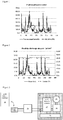
- the figure 1 shows a graph of the electrical power on a power train of an electric bicycle equipped with a 175-watt rated motor over a period of 5 minutes.
- the solid curve shows the instantaneous power and the dotted curve shows the average power over one minute.
- the instantaneous power varies from 0 to 600 Watts and the average power is about 100 Watts.
- the power train must incorporate a power battery capable of providing the maximum current required by the motor.
- the figure 2 shows a graph of the discharge profile of a battery used in the traction chain of the figure 1 .
- the battery has a nominal voltage of 24 volts and provides current peaks exceeding 25 amperes.
- the power required to provide the battery requires the use of accumulators having a power ratio on high weight (W / kg), said power type accumulators (or "power cell" in English terminology). These accumulators are capable of providing high current peaks but offer less energy than so-called energy-type accumulators. English terminology), ie having a high energy-to-weight ratio (Wh / kg), but can not provide strong currents.
- the documents FR-A-2 909 325 or GB-A-1 131 171 each describe a power supply device for an electrical machine comprising two energy sources.
- a first source includes batteries and a second source includes a fuel cell.
- the document FR-A-2,866,279 discloses a drive system of the driving wheels of a motor vehicle with electric motorization comprising two different complete power chains.
- Each drive chain comprises an electric motor and a rechargeable battery, the power of the engine of the second chain being greater than the power of the engine of the first chain.
- a high voltage network includes a high voltage battery and a low voltage network includes a low voltage battery.
- the system comprises a reversible electric energy converter arranged for, in a step-down mode, supplying electrical energy to the low-voltage grid from the electrical energy stored in the high-voltage battery, and for, in an elevator mode, supply electrical energy to the high voltage network from the electrical energy stored in the low voltage battery.
- the document FR-A-2,790,148 discloses an energy storage system which comprises at least two branches arranged in parallel, each branch comprising at least one electrochemical generator, the branches being of equal nominal voltages and different power to energy ratios.
- the document US-A-5,670,266 describes a hybrid energy storage system comprising a rechargeable battery and a capacitance.
- the capacity is adapted to meet the significant instantaneous power requirements of an electrical device.
- the documents GB-A-2,275,378 , DE-A-198 13 146 , GB-A-1,476,011 or GB-A-1,473,798 each describe a power source comprising a first energy type battery and a second power type battery.
- the known devices comprising a combination of power type and energy type batteries, are not well suited to autonomous systems for electric motorization for light vehicle or tool. Indeed, the known devices are relatively heavy and bulky and complex maintenance, in particular because the various elements of the battery device are not separable easily from the machine or the equipped device.
- the invention proposes an autonomous motorization system comprising a set of power-type accumulators associated with an engine and a set of removable and transportable energy-type accumulators.
- the invention proposes an autonomous motorization system according to claim 1.
- the invention also relates to a vehicle wheel comprising at least one autonomous motorization system according to one of claims 1 to 13 and to a tool comprising at least one autonomous motorization system according to one of claims 1 to 13.
- the invention also relates to a method of managing an electrically rechargeable battery pack according to claim 16.
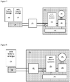
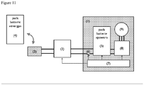
- the figure 3 shows a casing 1 serving to support an electric motor 9 and a set of power-type accumulators, hereinafter referred to as the power battery 5.
- the power battery 5 is adapted to power the motor 9, for example through a controller 8 which controls the operation of the engine, ie direction and rotation speed in particular.
- the motor 9 can be controlled by a simple switch actuated by a user; the controller 8 can then be a simple on / off type switch.
- the figure 3 also shows a central control unit 7 which supervises the management of the power battery 5 and controls the motor 9, through the controller 8 if necessary.
- the figure 3 still shows a set of energy-type accumulators, hereinafter referred to as energy battery 4.
- the energy battery 4 is removably arranged on a pedestal 3.
- a DC converter 2 connects the battery of energy 4 to the power battery 5.
- the figure 3 also shows a switching device 6 controlled by the central unit 7 and for interrupting the electrical connection between the energy battery 4 and the power battery 5.
- the electric motor 9 may be brushless DC type (BLDC for brushless DC motor in English) with permanent magnets.
- BLDC brushless DC type
- the casing 1 can be made of electrical insulating material and have mechanical properties which make it possible to guarantee the maintenance of the elements and the resistance to mechanical stresses to which the system is subjected, such as vibrations or shocks.
- the material of the housing 1 may be ABS-PC (Acrylonitrile Butadiene Styrene / Polycarbonate) or a composite material.
- the material of the casing 1 can also be plastic containing fillers (mineral particles for example) or reinforced (by glass fibers for example).
- the power battery 5 may be of Nickel Metal Hydride technology type power, or lithium-type power technology incorporating the appropriate protection functions.
- the energy battery 4 may also be of energy-type Lithium technology and integrate the appropriate protection functions (i.e. circuit breaker function and / or safety in case of overpressure for example).
- the power battery 5 supplies the instantaneous power consumed by the motor 9 and receives an average current of the energy battery 4 regulated by the converter 2.
- the converter 2 ensures that the current supplied to the power battery 5 is substantially equal to the average of the current consumed by the system over a long period.
- Converter 2 has an output profile suitable for directly charging the power battery 5.
- the charging of the power battery by the energy battery can to be controlled by the converter 2 or by the central unit 7.
- the central unit 7 can for example control the converter 2 ( figure 11 ).
- the central unit 7 can also interrupt the charging of the power battery at any time via the switching device 6.
- the central unit 7 may also include a control of the balancing of the accumulators of the power battery.
- the cut-off device 6 can be used as protection member of the power battery 5; the central unit 7 controlling the cut-off device 6 when it detects an operation of the power battery 5 outside the nominal ranges and / or when a SOC of 100% is reached. In one embodiment, the cut-off device 6 can be used to charge the power battery 5 with a pulsed load profile, for example during load balancing.
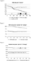
- the figure 4 illustrates the state of charge SOC of the power battery 5.
- the example of the figure 4 corresponds to the 5 minutes of operation of the system illustrated on the Figures 1 and 2 , and shows the SOC of the 5 power battery without recharging (bold line curve), the SOC of the 5 power battery with charging (curve dashed lines) and the active or inactive state of the charging device (fine line curve) .
- the state of charge of the power battery 5 without recharging decreases rapidly.
- the central unit 7 allows the charging of the power battery 5 by the energy battery 4 when the state of charge SOC is below a defined threshold, for example 80%.
- the power battery 5 is charged by the energy battery 4 through the converter 2.
- the converter 2 is a DC converter. It has an output characteristic adapted to the type of power battery 5 integrated in the system.
- the output of the converter 2 is comparable to that of a CCCV type charger (Constant Current / Constant Voltage constant current / constant voltage) with a voltage corresponding to the charging voltage of the battery (typically 4.2 V per accumulator). If the power battery 5 is of the Ni-MH type, the output of the converter 2 is of the DC (constant current) type with a current adapted to the charging regime of the accumulators and a voltage sufficient to fully charge the battery (typically 1.6 V per accumulator).
- the figure 5 illustrates the charge states SOC of the power battery 5 (solid line) and the energy battery 4 (dashed lines) and the figure 6 illustrates the voltages at the terminals of the power battery 5 (solid line) and the energy battery 4 (dashed lines).
- the state of charge of the battery energy decreases when a current is consumed on the energy battery 4, converted by the converter 2 and used to recharge the battery of power 5.
- the reading starts with a charged battery of energy 4, that is to say a 100% SOC.
- the maximum discharge current of the energy battery 4 depends on the current allowed by the accumulators that compose it.
- the energy-type accumulators can be discharged at a rate equal to 1 to 2 times their rated speed (C) equivalent to a discharge in one hour, ie 2 to 4 amperes for a battery of 2 Ah for example .
- the charging current of the power battery 5 is delivered by the converter 2 and can be greater than the discharge current of the energy battery 4 if the voltage of the power battery 5 is lower than the battery voltage d 4.
- the converter 2 is of type "buck" or step-down.
- the voltage of the energy battery 4 may also be lower than the voltage of the power battery 5, in this case the converter 2 is of the "boost" or lift type.
- the energy battery 4 consists of accumulators of 2.2 Ah and has a voltage of between 46 and 48 volts in operation.
- the power battery 5 has a voltage of about 26 volts.
- the energy battery 4 is discharged at a current of 3.3 amperes (1.5C or 1.5 times the nominal speed of the battery) when the system is active.
- the converter 2 is of the "buck" type with a yield of 95%; the charge current received by the power battery 5 is approximately 6 amperes, and decreases as the energy battery 4 discharges because its voltage decreases.
- the system according to the invention makes it possible to supply the power battery 5 with a charging current greater than the average current consumed by the motor 9 from the energy consumed on a battery of energy 4 that could not be used by it. only provide the instantaneous power demanded by the electric motor.
- the power battery 5 integrated in the system is almost never discharged, since the energy it provides to the motor 9 is on average compensated by the energy taken from the battery of energy 4.
- the energy battery 4 is removable; it can thus be recharged outside the system. Maintenance is simplified. In particular, it is possible to replace a battery of energy discharged by a new battery of energy 4 loaded, and this easily, quickly and possibly without interrupting the operation of the system. Indeed, the autonomous motorization system can operate with a reduced autonomy in the absence of the energy battery 4, the power battery 5 being sized to provide the instantaneous power required by the engine 9.
- a charger adapted to the battery of energy 4 is connected in upstream of converter 2 for charging the energy battery 4 and at the same time allow the charging of the power battery 5 via the converter 2.
- the energy battery 4 is removable and can be dissociated from the assembly without the need for a tool or complex operation, and can be connected and disconnected from the system thanks to an integrated electrical connector 3.
- the removability of the energy battery 4 allows it to be recharged on a charging station that is independent of the system, to immediately replace a battery discharged by a charged battery, or to use several batteries successively to increase the battery capacity. autonomy of the system.
- the power battery 5 can provide isolated power supply of the motor 9, which avoids stopping the system.
- the energy battery 4 can then be sized with a sufficiently low capacity to remain below the transport restriction thresholds.
- the energy battery 4 is sized to provide the average power demanded by the motor 9 instead of the maximum power required (in the example 100 Watts instead of 600 Watts). This makes possible the use of batteries of smaller power, but also of smaller energy, therefore of smaller size and lighter.
- the energy battery is of technology subject to transportation restrictions (eg Lithium)
- the possibility of using a small capacity battery allows to stay below the regulatory threshold (eg 100 Wh for restrictions "Class 9 "Lithium) and not to fall under the cover of restrictions.
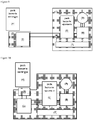
- FIG. 7 to 10 illustrate different embodiments of the autonomous motorization system according to the invention.
- the base 3 can receive several batteries of energy 4 to further increase the autonomy.
- the converter 2 is integrated in the casing 1 and according to the embodiment of the figure 9 , the converter 2 is integrated in the base 3 of the energy battery.
- the base 3 and the converter 2 are integrated in the housing 1.
- the central unit 7 controls the converter 2, for example with a setpoint device.
- the converter 2 can receive instructions from the central unit 7 so as to adapt its output to the load of the power battery 5. The control and load interruption functions can then be fully assured. by driving the converter 2 by the central unit 7.
- the cut-off device 6 can be retained to ensure redundant security.
- the motorization system according to the invention can be integrated with a wheel of a vehicle.
- the casing 1 may be secured to a chassis of the vehicle and an axis driven by the motor 9 may then be secured to the wheel.
- the wheel can be rotated by means of the axis rotated by the electric motor 9, the casing 1 remaining fixed.
- the axis driven by the motor is secured to the vehicle frame and the housing 1 is secured to the wheel.
- the wheel can be rotated through the casing 1 rotated by the electric motor 9.
- the elements supported by the casing 1 are distributed so as to avoid a swaying effect when rotating.
- the elements may be arranged around the drive shaft, so that the center of gravity of the system is in the center of the housing 1.
- the autonomous motorization system can be installed in many objects, for example in a light vehicle such as a bicycle, a scooter, a wheelbarrow, a stretcher or other; or in a tool such as a drill or other.
- a light vehicle such as a bicycle, a scooter, a wheelbarrow, a stretcher or other
- a tool such as a drill or other.
- the power battery In the case of a power-assisted bicycle equipped with a power train with a 250-watt motor, the power battery must provide power peaks up to 1 kW, and the average power consumed is 150 W.
- the power train consists of a motor and a removable battery which must be able to provide only the power demanded by the engine.
- the autonomous traction chain is composed of a motor 9 and a power battery 5 capable of providing the power demanded by the motor.
- the system further comprises a recharging device with a removable energy battery 4 capable of providing the average power demanded by the power train.
- the autonomous traction chain can be powered by two removable, compact and lightweight 100 Wh batteries.
- the casing 1 comprising the motor 9 and the power battery 5 can be arranged on the wheel and the frame must provide a housing for the battery of energy 4.
- This battery of energy 4 is capable alone to recharge the battery of power 5 and has a minimum footprint and does not require adaptation of the frame.
- Several energy batteries 4 can be used successively, one can be recharged while another is being used, and their transport is facilitated by their small size. If the batteries are Lithium batteries, they are not subject to the "Class 9" transport restrictions.
- each battery is of a size comparable to a laptop battery and does not is not subject to transportation restrictions.
- the maintenance of such a system is further facilitated by the possibility of disassociating the battery of energy from the entire system.
Landscapes
- Engineering & Computer Science (AREA)
- Power Engineering (AREA)
- Transportation (AREA)
- Mechanical Engineering (AREA)
- Life Sciences & Earth Sciences (AREA)
- Sustainable Development (AREA)
- Sustainable Energy (AREA)
- Charge And Discharge Circuits For Batteries Or The Like (AREA)
- Electric Propulsion And Braking For Vehicles (AREA)
- Control Of Multiple Motors (AREA)
- Battery Mounting, Suspending (AREA)
- Secondary Cells (AREA)
Claims (16)
- Autonomes Motorisierungssystem, das Folgendes umfasst:- mindestens einen Elektromotor (9),- eine Steuervorrichtung (8), die angepasst ist, um den Betrieb des Elektromotors (9) zu steuern,- eine Gruppe von elektrisch wiederaufladbaren Akkumulatoren des Leistungstyps (5),- einen Sockel (3), der angepasst ist, um, ohne Benötigung eines Werkzeugs, abnehmbar eine Gruppe von elektrisch wiederaufladbaren Akkumulatoren des Energietyps (4) aufzunehmen,- einen DC/DC-Wandler (2),- eine Steuerzentraleinheit (7), die angepasst ist, um den DC/DC-Wandler (2) zu steuern,wobei das autonome Motorisierungssystem dadurch gekennzeichnet ist, dass:- die Gruppe von elektrisch wiederaufladbaren Akkumulatoren des Leistungstyps (5) angepasst ist um den Motor (9) zu speisen, durch Lieferung des von dem Motor (9) verbrauchten Momentanstroms, wobei die Gruppe von elektrisch wiederaufladbaren Akkumulatoren des Leistungstyps (5) in der Lage ist, den, von dem Motor (9) geforderten Maximalstrom zu liefern,- der DC/DC-Wandler angepasst ist, um die Gruppe von elektrisch wiederaufladbaren Akkumulatoren des Energietyps (4) mit der Gruppe von elektrisch wiederaufladbaren Akkumulatoren des Leistungstyps (5) zu verbinden, um das Aufladen der elektrisch wiederaufladbaren Akkumulatoren des Leistungstyps (5) durch die Gruppe von elektrisch wiederaufladbaren Akkumulatoren des Energietyps (4) sicherzustellen, indem der Gruppe von elektrisch wiederaufladbaren Akkumulatoren des Leistungstyps (5) ein Ladestrom geliefert wird, der im Durchschnitt die an den Motor (9) gelieferte Energie ausgleicht.
- Autonomes Motorisierungssystem nach irgendeinem der vorhergehenden Ansprüche, das außerdem ein Ausschaltorgan (6) umfasst, das von der Steuerzentraleinheit (7) gesteuert wird und angepasst ist, um das Aufladen der Gruppe von elektrisch wiederaufladbaren Akkumulatoren des Leistungstyps (5) durch die Gruppe von elektrisch wiederaufladbaren Akkumulatoren des Energietyps (4) zu unterbrechen.
- Autonomes Motorisierungssystem nach Anspruch 2, wobei das Ausschaltorgan (6) so gesteuert ist, dass die Leistungsbatterie (5) mit einem gepulsten Lastprofil aufgeladen wird.
- Autonomes Motorisierungssystem nach irgendeinem der vorhergehenden Ansprüche, das außerdem ein Gehäuse (1) umfasst, das die Gruppe von elektrisch wiederaufladbaren Akkumulatoren des Leistungstyps (5), den Elektromotor (9), die Steuervorrichtung (8) und die Steuerzentraleinheit (7) trägt und fest verbindet.
- Autonomes Motorisierungssystem nach Anspruch 4, wobei das Gehäuse (1) außerdem den DC/DC-Wandler (2) trägt.
- Autonomes Motorisierungssystem nach Anspruch 4 oder 5, wobei das Gehäuse (1) außerdem den Sockel (3) trägt, der angepasst ist, um die Gruppe von elektrisch wiederaufladbaren Akkumulatoren des Energietyps (4) aufzunehmen.
- Autonomes Motorisierungssystem nach irgendeinem der vorhergehenden Ansprüche, wobei der Sockel (3) angepasst ist, um eine Vielzahl von Gruppen von elektrisch wiederaufladbaren Akkumulatoren des Energietyps (4) aufzunehmen.
- Autonomes Motorisierungssystem nach einem der Ansprüche 1 bis 7, wobei die Gruppe von elektrisch wiederaufladbaren Akkumulatoren des Leistungstyps (5) die Ni-MH-Technologie verwendet.
- Autonomes Motorisierungssystem nach Anspruch 8, wobei der DC/DC-Wandler (2) vom Typ Konstantstromausgang (CC) ist.
- Autonomes Motorisierungssystem nach einem der Ansprüche 1 bis 7, wobei die Gruppe von elektrisch wiederaufladbaren Akkumulatoren des Leistungstyps (5) die Lithium-Technologie verwendet.
- Autonomes Motorisierungssystem nach Anspruch 10, wobei der DC/DC-Wandler (2) vom Typ Konstantstromausgang und konstanter Spannung (CCCV) ist.
- Autonomes Motorisierungssystem nach irgendeinem der vorhergehenden Ansprüche, wobei die Gruppe von elektrisch wiederaufladbaren Akkumulatoren des Energietyps (4) die Lithium-Technologie verwendet.
- Autonomes Motorisierungssystem nach irgendeinem der vorhergehenden Ansprüche, wobei die Kapazität jeder Gruppe von elektrisch wiederaufladbaren Akkumulatoren (4, 5) kleiner oder gleich 100 Wh ist.
- Fahrzeugrad, das mindestens ein autonomes Motorisierungssystem nach einem der Ansprüche 1 bis 13 umfasst.
- Werkzeug, das mindestens ein autonomes Motorisierungssystem nach einem der Ansprüche 1 bis 13 umfasst.
- Verfahren zum Verwalten einer Gruppe von elektrisch wiederaufladbaren Akkumulatoren des Leistungstyps eines autonomen Motorisierungssystems nach einem der Ansprüche 1 bis 13, wobei das Verfahren dadurch gekennzeichnet ist, dass es Folgendes umfasst:- das Liefern durch die Gruppe von elektrisch wiederaufladbaren Akkumulatoren des Leistungstyps (5) des gesamten Momentanstroms, der von dem Motor (9) verbraucht wird,- das Aufladen der Gruppe von elektrisch wiederaufladbaren Akkumulatoren des Leistungstyps (5) durch einen Ladestrom, der im Durchschnitt die Energie, die an den Motor (9) geliefert wird, ausgleicht, den Wandler (2), der einen auf der Gruppe von elektrisch wiederaufladbaren Akkumulatoren des Energietyps (4) aufgenommenen Strom in den Ladestrom umwandelt, der von der Gruppe von elektrisch wiederaufladbaren Akkumulatoren des Leistungstyps (5) empfangen wird.
Priority Applications (10)
| Application Number | Priority Date | Filing Date | Title |
|---|---|---|---|
| DK10305321.1T DK2372864T3 (en) | 2010-03-29 | 2010-03-29 | Autonomous motorization system |
| EP10305321.1A EP2372864B1 (de) | 2010-03-29 | 2010-03-29 | Autonomes Motorisierungssystem |
| PL10305321T PL2372864T3 (pl) | 2010-03-29 | 2010-03-29 | Autonomiczny układ napędowy |
| ES10305321.1T ES2638299T3 (es) | 2010-03-29 | 2010-03-29 | Sistema de accionamiento autónomo |
| JP2013502014A JP2013524756A (ja) | 2010-03-29 | 2011-03-29 | 自己完結型動力供給システム |
| AU2011234086A AU2011234086A1 (en) | 2010-03-29 | 2011-03-29 | Autonomous motorization system |
| PCT/IB2011/051336 WO2011121543A2 (fr) | 2010-03-29 | 2011-03-29 | Système autonome de motorisation |
| CA2794431A CA2794431A1 (en) | 2010-03-29 | 2011-03-29 | Self-contained motorization system |
| NZ602641A NZ602641A (en) | 2010-03-29 | 2011-03-29 | Self-contained motorization system |
| US13/638,439 US9166433B2 (en) | 2010-03-29 | 2011-03-29 | Self-contained motorization system |
Applications Claiming Priority (1)
| Application Number | Priority Date | Filing Date | Title |
|---|---|---|---|
| EP10305321.1A EP2372864B1 (de) | 2010-03-29 | 2010-03-29 | Autonomes Motorisierungssystem |
Publications (2)
| Publication Number | Publication Date |
|---|---|
| EP2372864A1 EP2372864A1 (de) | 2011-10-05 |
| EP2372864B1 true EP2372864B1 (de) | 2017-05-24 |
Family
ID=42711131
Family Applications (1)
| Application Number | Title | Priority Date | Filing Date |
|---|---|---|---|
| EP10305321.1A Active EP2372864B1 (de) | 2010-03-29 | 2010-03-29 | Autonomes Motorisierungssystem |
Country Status (10)
| Country | Link |
|---|---|
| US (1) | US9166433B2 (de) |
| EP (1) | EP2372864B1 (de) |
| JP (1) | JP2013524756A (de) |
| AU (1) | AU2011234086A1 (de) |
| CA (1) | CA2794431A1 (de) |
| DK (1) | DK2372864T3 (de) |
| ES (1) | ES2638299T3 (de) |
| NZ (1) | NZ602641A (de) |
| PL (1) | PL2372864T3 (de) |
| WO (1) | WO2011121543A2 (de) |
Families Citing this family (11)
| Publication number | Priority date | Publication date | Assignee | Title |
|---|---|---|---|---|
| US9438113B2 (en) * | 2013-07-30 | 2016-09-06 | Johnson Controls Technology Company | DC-DC convertor for batteries having multiple positive terminals |
| EP3030453B1 (de) * | 2013-08-06 | 2019-06-19 | Gogoro Inc. | Systeme und verfahren zum antrieb elektrischer fahrzeuge mit einer einzelnen oder mehreren leistungszellen |
| CN104659921B (zh) * | 2013-11-26 | 2018-09-21 | 北京科易动力科技有限公司 | 车用复合储能系统 |
| DE102014201354A1 (de) * | 2014-01-27 | 2015-07-30 | Robert Bosch Gmbh | Bordnetz |
| CA2958880A1 (en) * | 2014-08-22 | 2016-02-25 | East Penn Manufacturing Co. | Control of multiple battery groups |
| GB2550954B (en) * | 2016-06-02 | 2022-02-23 | Arrival Ltd | Electric vehicle battery management apparatus and method |
| EP3678275A1 (de) * | 2017-08-30 | 2020-07-08 | Bernabé Panós, Jorge José | Wiederaufladesystem für elektrofahrzeuge |
| IT201900025813A1 (it) * | 2019-12-31 | 2021-07-01 | Valerio Torre | Struttura di bicicletta richiudibile |
| US12110217B2 (en) * | 2020-02-21 | 2024-10-08 | Michael Callahan | Chain motor power distribution and control |
| FR3114453B1 (fr) * | 2020-09-23 | 2023-08-11 | Orange | Dispositif d’alimentation |
| US20250050749A1 (en) | 2023-08-11 | 2025-02-13 | GM Global Technology Operations LLC | Cycle life management for mixed chemistry vehicle battery pack |
Citations (3)
| Publication number | Priority date | Publication date | Assignee | Title |
|---|---|---|---|---|
| US5780980A (en) * | 1995-04-14 | 1998-07-14 | Hitachi, Ltd. | Electric car drive system provided with hybrid battery and control method |
| US20040201365A1 (en) * | 2001-04-05 | 2004-10-14 | Electrovaya Inc. | Energy storage device for loads having variable power rates |
| US20050122071A1 (en) * | 2003-11-25 | 2005-06-09 | General Electric Company | Method and apparatus for producing tractive effort |
Family Cites Families (28)
| Publication number | Priority date | Publication date | Assignee | Title |
|---|---|---|---|---|
| GB1131171A (en) | 1966-10-24 | 1968-10-23 | Gen Electric | Fuel battery-rechargeable accumulator combination |
| US4056764A (en) | 1974-06-03 | 1977-11-01 | Nissan Motor Company, Limited | Power supply system having two different types of batteries and current-limiting circuit for lower output battery |
| JPS5344386B2 (de) | 1974-06-10 | 1978-11-28 | ||
| US3963976A (en) * | 1974-07-08 | 1976-06-15 | Utah Research & Development Co. | Pulsed current battery charging method and apparatus |
| GB2275378A (en) | 1993-02-22 | 1994-08-24 | Yang Tai Her | Compound battery power supply operable to deliver large pulse currents |
| US5659465A (en) * | 1994-09-23 | 1997-08-19 | Aeroviroment, Inc. | Peak electrical power conversion system |
| US5670861A (en) | 1995-01-17 | 1997-09-23 | Norvik Tractions Inc. | Battery energy monitoring circuits |
| US5670266A (en) | 1996-10-28 | 1997-09-23 | Motorola, Inc. | Hybrid energy storage system |
| JPH10271611A (ja) | 1997-03-25 | 1998-10-09 | Nissan Diesel Motor Co Ltd | 電気自動車の電源システム |
| JP3304835B2 (ja) * | 1997-08-06 | 2002-07-22 | トヨタ自動車株式会社 | ニッケルバッテリの充電方法およびその装置 |
| FR2790148B1 (fr) | 1999-02-22 | 2004-08-20 | Renault | Systeme de batterie flexible |
| JP3450220B2 (ja) * | 1999-04-16 | 2003-09-22 | 三菱電機株式会社 | 車両用電源装置 |
| JP3998118B2 (ja) * | 2000-10-10 | 2007-10-24 | 本田技研工業株式会社 | 電動車両 |
| JP2003048177A (ja) * | 2001-08-03 | 2003-02-18 | Nec Tokin Corp | 携帯型電動工具 |
| US6787951B2 (en) | 2001-10-01 | 2004-09-07 | Wavecrest Laboratories, Llc | Rotary electric motor having controller and power supply integrated therein |
| FR2836604B1 (fr) | 2002-02-22 | 2015-10-02 | Johnson Controls Automotive Electronics | Systeme d'alimentation electrique bi-tension |
| US6802385B2 (en) | 2002-05-16 | 2004-10-12 | Wavecrest Laboratories, Llc | Electrically powered vehicles having motor and power supply contained within wheels |
| WO2004050385A2 (en) | 2002-12-03 | 2004-06-17 | Radtke Jeffrey L | Self-propelled wheel for bicycles and other vehicles |
| US6791295B1 (en) * | 2003-02-20 | 2004-09-14 | Ford Global Technologies, Llc | Method and apparatus for charging a high voltage battery of an automotive vehicle having a high voltage battery and a low voltage battery |
| FR2866279B1 (fr) | 2004-02-18 | 2006-04-28 | Vehicules Electr Soc D | Systeme d'entrainement des roues motrices d'un vehicule automobile electrique, comprenant deux moteurs et deux batteries |
| JP2005245145A (ja) | 2004-02-27 | 2005-09-08 | Hitachi Koki Co Ltd | 充電装置 |
| US7148637B2 (en) * | 2005-05-12 | 2006-12-12 | Wiz Energy Technology, Co., Ltd. | Portable compound battery unit management system |
| FR2909325B1 (fr) | 2006-12-04 | 2009-03-06 | Peugeot Citroen Automobiles Sa | Dispositif d'alimentation pour une machine electrique de vehicule electrique a deux sources d'energie complementaires l'une de l'autre |
| KR100908716B1 (ko) | 2007-03-02 | 2009-07-22 | 삼성에스디아이 주식회사 | 배터리 관리 시스템 및 그의 구동 방법 |
| JP2009183074A (ja) * | 2008-01-31 | 2009-08-13 | Yokogawa Electric Corp | 外付けバッテリパックおよびこれを用いた電源装置 |
| JP2010038592A (ja) * | 2008-07-31 | 2010-02-18 | Sanyo Electric Co Ltd | パック電池 |
| US8957610B2 (en) * | 2009-07-02 | 2015-02-17 | Chong Uk Lee | Multi-port reconfigurable battery |
| WO2011050109A1 (en) * | 2009-10-20 | 2011-04-28 | Motiv Power Systems, Inc. | System and method for managing a power system with multiple power components |
-
2010
- 2010-03-29 PL PL10305321T patent/PL2372864T3/pl unknown
- 2010-03-29 ES ES10305321.1T patent/ES2638299T3/es active Active
- 2010-03-29 DK DK10305321.1T patent/DK2372864T3/en active
- 2010-03-29 EP EP10305321.1A patent/EP2372864B1/de active Active
-
2011
- 2011-03-29 WO PCT/IB2011/051336 patent/WO2011121543A2/fr not_active Ceased
- 2011-03-29 US US13/638,439 patent/US9166433B2/en not_active Expired - Fee Related
- 2011-03-29 NZ NZ602641A patent/NZ602641A/en not_active IP Right Cessation
- 2011-03-29 CA CA2794431A patent/CA2794431A1/en not_active Abandoned
- 2011-03-29 AU AU2011234086A patent/AU2011234086A1/en not_active Abandoned
- 2011-03-29 JP JP2013502014A patent/JP2013524756A/ja active Pending
Patent Citations (3)
| Publication number | Priority date | Publication date | Assignee | Title |
|---|---|---|---|---|
| US5780980A (en) * | 1995-04-14 | 1998-07-14 | Hitachi, Ltd. | Electric car drive system provided with hybrid battery and control method |
| US20040201365A1 (en) * | 2001-04-05 | 2004-10-14 | Electrovaya Inc. | Energy storage device for loads having variable power rates |
| US20050122071A1 (en) * | 2003-11-25 | 2005-06-09 | General Electric Company | Method and apparatus for producing tractive effort |
Also Published As
| Publication number | Publication date |
|---|---|
| US20130057182A1 (en) | 2013-03-07 |
| WO2011121543A3 (fr) | 2012-03-29 |
| AU2011234086A1 (en) | 2012-10-18 |
| US9166433B2 (en) | 2015-10-20 |
| DK2372864T3 (en) | 2017-09-18 |
| EP2372864A1 (de) | 2011-10-05 |
| PL2372864T3 (pl) | 2017-12-29 |
| CA2794431A1 (en) | 2011-10-06 |
| NZ602641A (en) | 2014-05-30 |
| WO2011121543A2 (fr) | 2011-10-06 |
| ES2638299T3 (es) | 2017-10-19 |
| JP2013524756A (ja) | 2013-06-17 |
Similar Documents
| Publication | Publication Date | Title |
|---|---|---|
| EP2372864B1 (de) | Autonomes Motorisierungssystem | |
| FR3006669A1 (fr) | Dispositif d’alimentation electrique pour aeronef a propulsion electrique | |
| FR3013164A1 (fr) | Procede de charge de vehicule electrique a vehicule electrique | |
| CA2875924A1 (fr) | Convertisseur reversible | |
| FR3039313B1 (fr) | Dispositif reconfigurable de stockage d'energie par effet capacitif, systeme d'alimentation et vehicule electrique integrant ce dispositif | |
| EP3947153B1 (de) | Hybridantriebseinheit für ein flugzeug | |
| EP1675744A2 (de) | Stromversorgungssysteme für ein elektromotorfahrzeug mit zwei batterien | |
| EP3771059A1 (de) | Verfahren zur stromversorgung eines elektrischen netzes und elektrische architektur | |
| EP3981056B1 (de) | Wiederaufladbare elektrische energiespeichervorrichtung und system, fahrzeug und anlage mit einem solchen system | |
| EP3472916B1 (de) | Verfahren und system zur intelligenten verwaltung von elektrochemischen batterien für ein elektrofahrzeug | |
| FR2889117A1 (fr) | Systeme d'entrainement des roues motrices d'un vehicule automobile electrique, comprenant deux moteurs, une batterie de puissance et une batterie d'energie | |
| FR2866279A1 (fr) | Systeme d'entrainement des roues motrices d'un vehicule automobile electrique, comprenant deux moteurs et deux batteries | |
| EP3377366A1 (de) | Verfahren und system zum elektrischen aufladen eines elektrofahrzeugs | |
| EP3472917B1 (de) | Verfahren und system zur verwaltung von elektrochemischen batterien eines elektrofahrzeugs im fall eines batterieausfalls | |
| EP4363321B1 (de) | Energieversorgungsmodul mit einer rückkopplungsschleife und einem dualen ausgang | |
| EP3342747B1 (de) | Zuführungsstruktur für gabelstapler | |
| FR3128580A1 (fr) | Dispositif de charge à accumulation électrique, système de charge à accumulation électrique, et batterie ion-lithium de traction rechargeable à courant élevé | |
| WO2020002820A1 (fr) | Système de stockage d'énergie embarqué | |
| FR2961131A1 (fr) | Vehicule electrique a generateur autonome extracible. | |
| FR2965123A1 (fr) | Dispositif et procede de gestion de l'alimentation en courant electrique d'une charge |
Legal Events
| Date | Code | Title | Description |
|---|---|---|---|
| PUAI | Public reference made under article 153(3) epc to a published international application that has entered the european phase |
Free format text: ORIGINAL CODE: 0009012 |
|
| AK | Designated contracting states |
Kind code of ref document: A1 Designated state(s): AT BE BG CH CY CZ DE DK EE ES FI FR GB GR HR HU IE IS IT LI LT LU LV MC MK MT NL NO PL PT RO SE SI SK SM TR |
|
| AX | Request for extension of the european patent |
Extension state: AL BA ME RS |
|
| 17P | Request for examination filed |
Effective date: 20120405 |
|
| 17Q | First examination report despatched |
Effective date: 20130715 |
|
| GRAP | Despatch of communication of intention to grant a patent |
Free format text: ORIGINAL CODE: EPIDOSNIGR1 |
|
| INTG | Intention to grant announced |
Effective date: 20161219 |
|
| GRAS | Grant fee paid |
Free format text: ORIGINAL CODE: EPIDOSNIGR3 |
|
| GRAA | (expected) grant |
Free format text: ORIGINAL CODE: 0009210 |
|
| AK | Designated contracting states |
Kind code of ref document: B1 Designated state(s): AT BE BG CH CY CZ DE DK EE ES FI FR GB GR HR HU IE IS IT LI LT LU LV MC MK MT NL NO PL PT RO SE SI SK SM TR |
|
| REG | Reference to a national code |
Ref country code: GB Ref legal event code: FG4D Free format text: NOT ENGLISH |
|
| REG | Reference to a national code |
Ref country code: CH Ref legal event code: EP |
|
| REG | Reference to a national code |
Ref country code: IE Ref legal event code: FG4D Free format text: LANGUAGE OF EP DOCUMENT: FRENCH |
|
| REG | Reference to a national code |
Ref country code: AT Ref legal event code: REF Ref document number: 896438 Country of ref document: AT Kind code of ref document: T Effective date: 20170615 |
|
| REG | Reference to a national code |
Ref country code: DE Ref legal event code: R096 Ref document number: 602010042533 Country of ref document: DE |
|
| REG | Reference to a national code |
Ref country code: NL Ref legal event code: FP |
|
| REG | Reference to a national code |
Ref country code: CH Ref legal event code: NV Representative=s name: WEINMANN ZIMMERLI, CH |
|
| REG | Reference to a national code |
Ref country code: DK Ref legal event code: T3 Effective date: 20170911 |
|
| REG | Reference to a national code |
Ref country code: SE Ref legal event code: TRGR |
|
| REG | Reference to a national code |
Ref country code: LT Ref legal event code: MG4D |
|
| REG | Reference to a national code |
Ref country code: AT Ref legal event code: MK05 Ref document number: 896438 Country of ref document: AT Kind code of ref document: T Effective date: 20170524 |
|
| REG | Reference to a national code |
Ref country code: ES Ref legal event code: FG2A Ref document number: 2638299 Country of ref document: ES Kind code of ref document: T3 Effective date: 20171019 |
|
| REG | Reference to a national code |
Ref country code: NO Ref legal event code: T2 Effective date: 20170524 |
|
| PG25 | Lapsed in a contracting state [announced via postgrant information from national office to epo] |
Ref country code: AT Free format text: LAPSE BECAUSE OF FAILURE TO SUBMIT A TRANSLATION OF THE DESCRIPTION OR TO PAY THE FEE WITHIN THE PRESCRIBED TIME-LIMIT Effective date: 20170524 Ref country code: HR Free format text: LAPSE BECAUSE OF FAILURE TO SUBMIT A TRANSLATION OF THE DESCRIPTION OR TO PAY THE FEE WITHIN THE PRESCRIBED TIME-LIMIT Effective date: 20170524 Ref country code: GR Free format text: LAPSE BECAUSE OF FAILURE TO SUBMIT A TRANSLATION OF THE DESCRIPTION OR TO PAY THE FEE WITHIN THE PRESCRIBED TIME-LIMIT Effective date: 20170825 Ref country code: LT Free format text: LAPSE BECAUSE OF FAILURE TO SUBMIT A TRANSLATION OF THE DESCRIPTION OR TO PAY THE FEE WITHIN THE PRESCRIBED TIME-LIMIT Effective date: 20170524 Ref country code: FI Free format text: LAPSE BECAUSE OF FAILURE TO SUBMIT A TRANSLATION OF THE DESCRIPTION OR TO PAY THE FEE WITHIN THE PRESCRIBED TIME-LIMIT Effective date: 20170524 |
|
| PG25 | Lapsed in a contracting state [announced via postgrant information from national office to epo] |
Ref country code: IS Free format text: LAPSE BECAUSE OF FAILURE TO SUBMIT A TRANSLATION OF THE DESCRIPTION OR TO PAY THE FEE WITHIN THE PRESCRIBED TIME-LIMIT Effective date: 20170924 Ref country code: BG Free format text: LAPSE BECAUSE OF FAILURE TO SUBMIT A TRANSLATION OF THE DESCRIPTION OR TO PAY THE FEE WITHIN THE PRESCRIBED TIME-LIMIT Effective date: 20170824 Ref country code: LV Free format text: LAPSE BECAUSE OF FAILURE TO SUBMIT A TRANSLATION OF THE DESCRIPTION OR TO PAY THE FEE WITHIN THE PRESCRIBED TIME-LIMIT Effective date: 20170524 |
|
| REG | Reference to a national code |
Ref country code: FR Ref legal event code: PLFP Year of fee payment: 9 |
|
| PG25 | Lapsed in a contracting state [announced via postgrant information from national office to epo] |
Ref country code: EE Free format text: LAPSE BECAUSE OF FAILURE TO SUBMIT A TRANSLATION OF THE DESCRIPTION OR TO PAY THE FEE WITHIN THE PRESCRIBED TIME-LIMIT Effective date: 20170524 Ref country code: RO Free format text: LAPSE BECAUSE OF FAILURE TO SUBMIT A TRANSLATION OF THE DESCRIPTION OR TO PAY THE FEE WITHIN THE PRESCRIBED TIME-LIMIT Effective date: 20170524 Ref country code: SK Free format text: LAPSE BECAUSE OF FAILURE TO SUBMIT A TRANSLATION OF THE DESCRIPTION OR TO PAY THE FEE WITHIN THE PRESCRIBED TIME-LIMIT Effective date: 20170524 Ref country code: CZ Free format text: LAPSE BECAUSE OF FAILURE TO SUBMIT A TRANSLATION OF THE DESCRIPTION OR TO PAY THE FEE WITHIN THE PRESCRIBED TIME-LIMIT Effective date: 20170524 |
|
| REG | Reference to a national code |
Ref country code: DE Ref legal event code: R097 Ref document number: 602010042533 Country of ref document: DE |
|
| PG25 | Lapsed in a contracting state [announced via postgrant information from national office to epo] |
Ref country code: SM Free format text: LAPSE BECAUSE OF FAILURE TO SUBMIT A TRANSLATION OF THE DESCRIPTION OR TO PAY THE FEE WITHIN THE PRESCRIBED TIME-LIMIT Effective date: 20170524 |
|
| PLBE | No opposition filed within time limit |
Free format text: ORIGINAL CODE: 0009261 |
|
| STAA | Information on the status of an ep patent application or granted ep patent |
Free format text: STATUS: NO OPPOSITION FILED WITHIN TIME LIMIT |
|
| 26N | No opposition filed |
Effective date: 20180227 |
|
| PG25 | Lapsed in a contracting state [announced via postgrant information from national office to epo] |
Ref country code: SI Free format text: LAPSE BECAUSE OF FAILURE TO SUBMIT A TRANSLATION OF THE DESCRIPTION OR TO PAY THE FEE WITHIN THE PRESCRIBED TIME-LIMIT Effective date: 20170524 |
|
| PG25 | Lapsed in a contracting state [announced via postgrant information from national office to epo] |
Ref country code: MT Free format text: LAPSE BECAUSE OF FAILURE TO SUBMIT A TRANSLATION OF THE DESCRIPTION OR TO PAY THE FEE WITHIN THE PRESCRIBED TIME-LIMIT Effective date: 20170524 |
|
| REG | Reference to a national code |
Ref country code: IE Ref legal event code: MM4A |
|
| PG25 | Lapsed in a contracting state [announced via postgrant information from national office to epo] |
Ref country code: IE Free format text: LAPSE BECAUSE OF NON-PAYMENT OF DUE FEES Effective date: 20180329 |
|
| PG25 | Lapsed in a contracting state [announced via postgrant information from national office to epo] |
Ref country code: TR Free format text: LAPSE BECAUSE OF FAILURE TO SUBMIT A TRANSLATION OF THE DESCRIPTION OR TO PAY THE FEE WITHIN THE PRESCRIBED TIME-LIMIT Effective date: 20170524 |
|
| PG25 | Lapsed in a contracting state [announced via postgrant information from national office to epo] |
Ref country code: HU Free format text: LAPSE BECAUSE OF FAILURE TO SUBMIT A TRANSLATION OF THE DESCRIPTION OR TO PAY THE FEE WITHIN THE PRESCRIBED TIME-LIMIT; INVALID AB INITIO Effective date: 20100329 Ref country code: PT Free format text: LAPSE BECAUSE OF FAILURE TO SUBMIT A TRANSLATION OF THE DESCRIPTION OR TO PAY THE FEE WITHIN THE PRESCRIBED TIME-LIMIT Effective date: 20170524 |
|
| PG25 | Lapsed in a contracting state [announced via postgrant information from national office to epo] |
Ref country code: CY Free format text: LAPSE BECAUSE OF FAILURE TO SUBMIT A TRANSLATION OF THE DESCRIPTION OR TO PAY THE FEE WITHIN THE PRESCRIBED TIME-LIMIT Effective date: 20170524 Ref country code: MK Free format text: LAPSE BECAUSE OF NON-PAYMENT OF DUE FEES Effective date: 20170524 |
|
| REG | Reference to a national code |
Ref country code: DK Ref legal event code: EBP Effective date: 20200331 |
|
| PGFP | Annual fee paid to national office [announced via postgrant information from national office to epo] |
Ref country code: NL Payment date: 20220331 Year of fee payment: 13 |
|
| PGFP | Annual fee paid to national office [announced via postgrant information from national office to epo] |
Ref country code: NO Payment date: 20220401 Year of fee payment: 13 |
|
| PGFP | Annual fee paid to national office [announced via postgrant information from national office to epo] |
Ref country code: IT Payment date: 20230331 Year of fee payment: 14 |
|
| REG | Reference to a national code |
Ref country code: NO Ref legal event code: MMEP |
|
| REG | Reference to a national code |
Ref country code: NL Ref legal event code: MM Effective date: 20230401 |
|
| PG25 | Lapsed in a contracting state [announced via postgrant information from national office to epo] |
Ref country code: NL Free format text: LAPSE BECAUSE OF NON-PAYMENT OF DUE FEES Effective date: 20230401 |
|
| PG25 | Lapsed in a contracting state [announced via postgrant information from national office to epo] |
Ref country code: NO Free format text: LAPSE BECAUSE OF NON-PAYMENT OF DUE FEES Effective date: 20230331 |
|
| PGFP | Annual fee paid to national office [announced via postgrant information from national office to epo] |
Ref country code: DE Payment date: 20250331 Year of fee payment: 16 |
|
| PGFP | Annual fee paid to national office [announced via postgrant information from national office to epo] |
Ref country code: FR Payment date: 20250331 Year of fee payment: 16 |
|
| PG25 | Lapsed in a contracting state [announced via postgrant information from national office to epo] |
Ref country code: IT Free format text: LAPSE BECAUSE OF NON-PAYMENT OF DUE FEES Effective date: 20240329 |
|
| PGFP | Annual fee paid to national office [announced via postgrant information from national office to epo] |
Ref country code: GB Payment date: 20250331 Year of fee payment: 16 |
|
| PGFP | Annual fee paid to national office [announced via postgrant information from national office to epo] |
Ref country code: LU Payment date: 20250731 Year of fee payment: 16 |
|
| PGFP | Annual fee paid to national office [announced via postgrant information from national office to epo] |
Ref country code: DK Payment date: 20250806 Year of fee payment: 16 |
|
| PG25 | Lapsed in a contracting state [announced via postgrant information from national office to epo] |
Ref country code: MC Free format text: LAPSE BECAUSE OF NON-PAYMENT OF DUE FEES Effective date: 20250331 |
|
| PGFP | Annual fee paid to national office [announced via postgrant information from national office to epo] |
Ref country code: PL Payment date: 20250806 Year of fee payment: 16 |
|
| PGFP | Annual fee paid to national office [announced via postgrant information from national office to epo] |
Ref country code: BE Payment date: 20250729 Year of fee payment: 16 |
|
| PGFP | Annual fee paid to national office [announced via postgrant information from national office to epo] |
Ref country code: CH Payment date: 20250805 Year of fee payment: 16 Ref country code: SE Payment date: 20250806 Year of fee payment: 16 |
|
| PGFP | Annual fee paid to national office [announced via postgrant information from national office to epo] |
Ref country code: MC Payment date: 20251003 Year of fee payment: 16 |
|
| PGFP | Annual fee paid to national office [announced via postgrant information from national office to epo] |
Ref country code: ES Payment date: 20251002 Year of fee payment: 16 |