EP3086972B1 - Véhicule comportant un groupe électrogène - Google Patents
Véhicule comportant un groupe électrogène Download PDFInfo
- Publication number
- EP3086972B1 EP3086972B1 EP14835482.2A EP14835482A EP3086972B1 EP 3086972 B1 EP3086972 B1 EP 3086972B1 EP 14835482 A EP14835482 A EP 14835482A EP 3086972 B1 EP3086972 B1 EP 3086972B1
- Authority
- EP
- European Patent Office
- Prior art keywords
- vehicle
- battery
- auxiliary connector
- distribution device
- connector
- Prior art date
- Legal status (The legal status is an assumption and is not a legal conclusion. Google has not performed a legal analysis and makes no representation as to the accuracy of the status listed.)
- Active
Links
- 230000005611 electricity Effects 0.000 title description 6
- 239000004606 Fillers/Extenders Substances 0.000 claims description 12
- 238000000034 method Methods 0.000 claims description 8
- 230000001105 regulatory effect Effects 0.000 claims description 6
- 238000013500 data storage Methods 0.000 claims description 2
- 238000001514 detection method Methods 0.000 claims description 2
- 230000006872 improvement Effects 0.000 description 5
- 238000004364 calculation method Methods 0.000 description 4
- 239000000446 fuel Substances 0.000 description 4
- 239000003638 chemical reducing agent Substances 0.000 description 2
- 238000005265 energy consumption Methods 0.000 description 2
- 230000007613 environmental effect Effects 0.000 description 2
- 238000009396 hybridization Methods 0.000 description 2
- 238000013475 authorization Methods 0.000 description 1
- 239000003795 chemical substances by application Substances 0.000 description 1
- 238000002485 combustion reaction Methods 0.000 description 1
- 238000005315 distribution function Methods 0.000 description 1
- 230000000694 effects Effects 0.000 description 1
- 238000010438 heat treatment Methods 0.000 description 1
- 238000009434 installation Methods 0.000 description 1
- 238000011176 pooling Methods 0.000 description 1
- 238000003825 pressing Methods 0.000 description 1
- 230000009467 reduction Effects 0.000 description 1
- 238000011144 upstream manufacturing Methods 0.000 description 1
Images

Classifications
-
- B—PERFORMING OPERATIONS; TRANSPORTING
- B60—VEHICLES IN GENERAL
- B60K—ARRANGEMENT OR MOUNTING OF PROPULSION UNITS OR OF TRANSMISSIONS IN VEHICLES; ARRANGEMENT OR MOUNTING OF PLURAL DIVERSE PRIME-MOVERS IN VEHICLES; AUXILIARY DRIVES FOR VEHICLES; INSTRUMENTATION OR DASHBOARDS FOR VEHICLES; ARRANGEMENTS IN CONNECTION WITH COOLING, AIR INTAKE, GAS EXHAUST OR FUEL SUPPLY OF PROPULSION UNITS IN VEHICLES
- B60K6/00—Arrangement or mounting of plural diverse prime-movers for mutual or common propulsion, e.g. hybrid propulsion systems comprising electric motors and internal combustion engines ; Control systems therefor, i.e. systems controlling two or more prime movers, or controlling one of these prime movers and any of the transmission, drive or drive units Informative references: mechanical gearings with secondary electric drive F16H3/72; arrangements for handling mechanical energy structurally associated with the dynamo-electric machine H02K7/00; machines comprising structurally interrelated motor and generator parts H02K51/00; dynamo-electric machines not otherwise provided for in H02K see H02K99/00
- B60K6/20—Arrangement or mounting of plural diverse prime-movers for mutual or common propulsion, e.g. hybrid propulsion systems comprising electric motors and internal combustion engines ; Control systems therefor, i.e. systems controlling two or more prime movers, or controlling one of these prime movers and any of the transmission, drive or drive units Informative references: mechanical gearings with secondary electric drive F16H3/72; arrangements for handling mechanical energy structurally associated with the dynamo-electric machine H02K7/00; machines comprising structurally interrelated motor and generator parts H02K51/00; dynamo-electric machines not otherwise provided for in H02K see H02K99/00 the prime-movers consisting of electric motors and internal combustion engines, e.g. HEVs
- B60K6/42—Arrangement or mounting of plural diverse prime-movers for mutual or common propulsion, e.g. hybrid propulsion systems comprising electric motors and internal combustion engines ; Control systems therefor, i.e. systems controlling two or more prime movers, or controlling one of these prime movers and any of the transmission, drive or drive units Informative references: mechanical gearings with secondary electric drive F16H3/72; arrangements for handling mechanical energy structurally associated with the dynamo-electric machine H02K7/00; machines comprising structurally interrelated motor and generator parts H02K51/00; dynamo-electric machines not otherwise provided for in H02K see H02K99/00 the prime-movers consisting of electric motors and internal combustion engines, e.g. HEVs characterised by the architecture of the hybrid electric vehicle
- B60K6/46—Series type
-
- B—PERFORMING OPERATIONS; TRANSPORTING
- B60—VEHICLES IN GENERAL
- B60K—ARRANGEMENT OR MOUNTING OF PROPULSION UNITS OR OF TRANSMISSIONS IN VEHICLES; ARRANGEMENT OR MOUNTING OF PLURAL DIVERSE PRIME-MOVERS IN VEHICLES; AUXILIARY DRIVES FOR VEHICLES; INSTRUMENTATION OR DASHBOARDS FOR VEHICLES; ARRANGEMENTS IN CONNECTION WITH COOLING, AIR INTAKE, GAS EXHAUST OR FUEL SUPPLY OF PROPULSION UNITS IN VEHICLES
- B60K15/00—Arrangement in connection with fuel supply of combustion engines or other fuel consuming energy converters, e.g. fuel cells; Mounting or construction of fuel tanks
- B60K15/03—Fuel tanks
- B60K15/063—Arrangement of tanks
- B60K15/067—Mounting of tanks
- B60K15/07—Mounting of tanks of gas tanks
-
- B—PERFORMING OPERATIONS; TRANSPORTING
- B60—VEHICLES IN GENERAL
- B60L—PROPULSION OF ELECTRICALLY-PROPELLED VEHICLES; SUPPLYING ELECTRIC POWER FOR AUXILIARY EQUIPMENT OF ELECTRICALLY-PROPELLED VEHICLES; ELECTRODYNAMIC BRAKE SYSTEMS FOR VEHICLES IN GENERAL; MAGNETIC SUSPENSION OR LEVITATION FOR VEHICLES; MONITORING OPERATING VARIABLES OF ELECTRICALLY-PROPELLED VEHICLES; ELECTRIC SAFETY DEVICES FOR ELECTRICALLY-PROPELLED VEHICLES
- B60L1/00—Supplying electric power to auxiliary equipment of vehicles
- B60L1/006—Supplying electric power to auxiliary equipment of vehicles to power outlets
-
- B—PERFORMING OPERATIONS; TRANSPORTING
- B60—VEHICLES IN GENERAL
- B60L—PROPULSION OF ELECTRICALLY-PROPELLED VEHICLES; SUPPLYING ELECTRIC POWER FOR AUXILIARY EQUIPMENT OF ELECTRICALLY-PROPELLED VEHICLES; ELECTRODYNAMIC BRAKE SYSTEMS FOR VEHICLES IN GENERAL; MAGNETIC SUSPENSION OR LEVITATION FOR VEHICLES; MONITORING OPERATING VARIABLES OF ELECTRICALLY-PROPELLED VEHICLES; ELECTRIC SAFETY DEVICES FOR ELECTRICALLY-PROPELLED VEHICLES
- B60L3/00—Electric devices on electrically-propelled vehicles for safety purposes; Monitoring operating variables, e.g. speed, deceleration or energy consumption
- B60L3/0023—Detecting, eliminating, remedying or compensating for drive train abnormalities, e.g. failures within the drive train
- B60L3/0046—Detecting, eliminating, remedying or compensating for drive train abnormalities, e.g. failures within the drive train relating to electric energy storage systems, e.g. batteries or capacitors
-
- B—PERFORMING OPERATIONS; TRANSPORTING
- B60—VEHICLES IN GENERAL
- B60L—PROPULSION OF ELECTRICALLY-PROPELLED VEHICLES; SUPPLYING ELECTRIC POWER FOR AUXILIARY EQUIPMENT OF ELECTRICALLY-PROPELLED VEHICLES; ELECTRODYNAMIC BRAKE SYSTEMS FOR VEHICLES IN GENERAL; MAGNETIC SUSPENSION OR LEVITATION FOR VEHICLES; MONITORING OPERATING VARIABLES OF ELECTRICALLY-PROPELLED VEHICLES; ELECTRIC SAFETY DEVICES FOR ELECTRICALLY-PROPELLED VEHICLES
- B60L3/00—Electric devices on electrically-propelled vehicles for safety purposes; Monitoring operating variables, e.g. speed, deceleration or energy consumption
- B60L3/0023—Detecting, eliminating, remedying or compensating for drive train abnormalities, e.g. failures within the drive train
- B60L3/0061—Detecting, eliminating, remedying or compensating for drive train abnormalities, e.g. failures within the drive train relating to electrical machines
-
- B—PERFORMING OPERATIONS; TRANSPORTING
- B60—VEHICLES IN GENERAL
- B60L—PROPULSION OF ELECTRICALLY-PROPELLED VEHICLES; SUPPLYING ELECTRIC POWER FOR AUXILIARY EQUIPMENT OF ELECTRICALLY-PROPELLED VEHICLES; ELECTRODYNAMIC BRAKE SYSTEMS FOR VEHICLES IN GENERAL; MAGNETIC SUSPENSION OR LEVITATION FOR VEHICLES; MONITORING OPERATING VARIABLES OF ELECTRICALLY-PROPELLED VEHICLES; ELECTRIC SAFETY DEVICES FOR ELECTRICALLY-PROPELLED VEHICLES
- B60L50/00—Electric propulsion with power supplied within the vehicle
- B60L50/50—Electric propulsion with power supplied within the vehicle using propulsion power supplied by batteries or fuel cells
- B60L50/60—Electric propulsion with power supplied within the vehicle using propulsion power supplied by batteries or fuel cells using power supplied by batteries
- B60L50/61—Electric propulsion with power supplied within the vehicle using propulsion power supplied by batteries or fuel cells using power supplied by batteries by batteries charged by engine-driven generators, e.g. series hybrid electric vehicles
-
- B—PERFORMING OPERATIONS; TRANSPORTING
- B60—VEHICLES IN GENERAL
- B60L—PROPULSION OF ELECTRICALLY-PROPELLED VEHICLES; SUPPLYING ELECTRIC POWER FOR AUXILIARY EQUIPMENT OF ELECTRICALLY-PROPELLED VEHICLES; ELECTRODYNAMIC BRAKE SYSTEMS FOR VEHICLES IN GENERAL; MAGNETIC SUSPENSION OR LEVITATION FOR VEHICLES; MONITORING OPERATING VARIABLES OF ELECTRICALLY-PROPELLED VEHICLES; ELECTRIC SAFETY DEVICES FOR ELECTRICALLY-PROPELLED VEHICLES
- B60L58/00—Methods or circuit arrangements for monitoring or controlling batteries or fuel cells, specially adapted for electric vehicles
- B60L58/10—Methods or circuit arrangements for monitoring or controlling batteries or fuel cells, specially adapted for electric vehicles for monitoring or controlling batteries
- B60L58/12—Methods or circuit arrangements for monitoring or controlling batteries or fuel cells, specially adapted for electric vehicles for monitoring or controlling batteries responding to state of charge [SoC]
- B60L58/14—Preventing excessive discharging
-
- B—PERFORMING OPERATIONS; TRANSPORTING
- B60—VEHICLES IN GENERAL
- B60L—PROPULSION OF ELECTRICALLY-PROPELLED VEHICLES; SUPPLYING ELECTRIC POWER FOR AUXILIARY EQUIPMENT OF ELECTRICALLY-PROPELLED VEHICLES; ELECTRODYNAMIC BRAKE SYSTEMS FOR VEHICLES IN GENERAL; MAGNETIC SUSPENSION OR LEVITATION FOR VEHICLES; MONITORING OPERATING VARIABLES OF ELECTRICALLY-PROPELLED VEHICLES; ELECTRIC SAFETY DEVICES FOR ELECTRICALLY-PROPELLED VEHICLES
- B60L58/00—Methods or circuit arrangements for monitoring or controlling batteries or fuel cells, specially adapted for electric vehicles
- B60L58/40—Methods or circuit arrangements for monitoring or controlling batteries or fuel cells, specially adapted for electric vehicles for controlling a combination of batteries and fuel cells
-
- B—PERFORMING OPERATIONS; TRANSPORTING
- B60—VEHICLES IN GENERAL
- B60W—CONJOINT CONTROL OF VEHICLE SUB-UNITS OF DIFFERENT TYPE OR DIFFERENT FUNCTION; CONTROL SYSTEMS SPECIALLY ADAPTED FOR HYBRID VEHICLES; ROAD VEHICLE DRIVE CONTROL SYSTEMS FOR PURPOSES NOT RELATED TO THE CONTROL OF A PARTICULAR SUB-UNIT
- B60W10/00—Conjoint control of vehicle sub-units of different type or different function
- B60W10/04—Conjoint control of vehicle sub-units of different type or different function including control of propulsion units
- B60W10/06—Conjoint control of vehicle sub-units of different type or different function including control of propulsion units including control of combustion engines
-
- B—PERFORMING OPERATIONS; TRANSPORTING
- B60—VEHICLES IN GENERAL
- B60W—CONJOINT CONTROL OF VEHICLE SUB-UNITS OF DIFFERENT TYPE OR DIFFERENT FUNCTION; CONTROL SYSTEMS SPECIALLY ADAPTED FOR HYBRID VEHICLES; ROAD VEHICLE DRIVE CONTROL SYSTEMS FOR PURPOSES NOT RELATED TO THE CONTROL OF A PARTICULAR SUB-UNIT
- B60W10/00—Conjoint control of vehicle sub-units of different type or different function
- B60W10/04—Conjoint control of vehicle sub-units of different type or different function including control of propulsion units
- B60W10/08—Conjoint control of vehicle sub-units of different type or different function including control of propulsion units including control of electric propulsion units, e.g. motors or generators
-
- B—PERFORMING OPERATIONS; TRANSPORTING
- B60—VEHICLES IN GENERAL
- B60W—CONJOINT CONTROL OF VEHICLE SUB-UNITS OF DIFFERENT TYPE OR DIFFERENT FUNCTION; CONTROL SYSTEMS SPECIALLY ADAPTED FOR HYBRID VEHICLES; ROAD VEHICLE DRIVE CONTROL SYSTEMS FOR PURPOSES NOT RELATED TO THE CONTROL OF A PARTICULAR SUB-UNIT
- B60W10/00—Conjoint control of vehicle sub-units of different type or different function
- B60W10/24—Conjoint control of vehicle sub-units of different type or different function including control of energy storage means
- B60W10/26—Conjoint control of vehicle sub-units of different type or different function including control of energy storage means for electrical energy, e.g. batteries or capacitors
-
- B—PERFORMING OPERATIONS; TRANSPORTING
- B60—VEHICLES IN GENERAL
- B60W—CONJOINT CONTROL OF VEHICLE SUB-UNITS OF DIFFERENT TYPE OR DIFFERENT FUNCTION; CONTROL SYSTEMS SPECIALLY ADAPTED FOR HYBRID VEHICLES; ROAD VEHICLE DRIVE CONTROL SYSTEMS FOR PURPOSES NOT RELATED TO THE CONTROL OF A PARTICULAR SUB-UNIT
- B60W10/00—Conjoint control of vehicle sub-units of different type or different function
- B60W10/30—Conjoint control of vehicle sub-units of different type or different function including control of auxiliary equipment, e.g. air-conditioning compressors or oil pumps
-
- B—PERFORMING OPERATIONS; TRANSPORTING
- B60—VEHICLES IN GENERAL
- B60W—CONJOINT CONTROL OF VEHICLE SUB-UNITS OF DIFFERENT TYPE OR DIFFERENT FUNCTION; CONTROL SYSTEMS SPECIALLY ADAPTED FOR HYBRID VEHICLES; ROAD VEHICLE DRIVE CONTROL SYSTEMS FOR PURPOSES NOT RELATED TO THE CONTROL OF A PARTICULAR SUB-UNIT
- B60W30/00—Purposes of road vehicle drive control systems not related to the control of a particular sub-unit, e.g. of systems using conjoint control of vehicle sub-units, or advanced driver assistance systems for ensuring comfort, stability and safety or drive control systems for propelling or retarding the vehicle
- B60W30/18—Propelling the vehicle
- B60W30/18009—Propelling the vehicle related to particular drive situations
-
- B—PERFORMING OPERATIONS; TRANSPORTING
- B60—VEHICLES IN GENERAL
- B60K—ARRANGEMENT OR MOUNTING OF PROPULSION UNITS OR OF TRANSMISSIONS IN VEHICLES; ARRANGEMENT OR MOUNTING OF PLURAL DIVERSE PRIME-MOVERS IN VEHICLES; AUXILIARY DRIVES FOR VEHICLES; INSTRUMENTATION OR DASHBOARDS FOR VEHICLES; ARRANGEMENTS IN CONNECTION WITH COOLING, AIR INTAKE, GAS EXHAUST OR FUEL SUPPLY OF PROPULSION UNITS IN VEHICLES
- B60K1/00—Arrangement or mounting of electrical propulsion units
- B60K2001/001—Arrangement or mounting of electrical propulsion units one motor mounted on a propulsion axle for rotating right and left wheels of this axle
-
- B—PERFORMING OPERATIONS; TRANSPORTING
- B60—VEHICLES IN GENERAL
- B60L—PROPULSION OF ELECTRICALLY-PROPELLED VEHICLES; SUPPLYING ELECTRIC POWER FOR AUXILIARY EQUIPMENT OF ELECTRICALLY-PROPELLED VEHICLES; ELECTRODYNAMIC BRAKE SYSTEMS FOR VEHICLES IN GENERAL; MAGNETIC SUSPENSION OR LEVITATION FOR VEHICLES; MONITORING OPERATING VARIABLES OF ELECTRICALLY-PROPELLED VEHICLES; ELECTRIC SAFETY DEVICES FOR ELECTRICALLY-PROPELLED VEHICLES
- B60L2210/00—Converter types
- B60L2210/40—DC to AC converters
-
- B—PERFORMING OPERATIONS; TRANSPORTING
- B60—VEHICLES IN GENERAL
- B60L—PROPULSION OF ELECTRICALLY-PROPELLED VEHICLES; SUPPLYING ELECTRIC POWER FOR AUXILIARY EQUIPMENT OF ELECTRICALLY-PROPELLED VEHICLES; ELECTRODYNAMIC BRAKE SYSTEMS FOR VEHICLES IN GENERAL; MAGNETIC SUSPENSION OR LEVITATION FOR VEHICLES; MONITORING OPERATING VARIABLES OF ELECTRICALLY-PROPELLED VEHICLES; ELECTRIC SAFETY DEVICES FOR ELECTRICALLY-PROPELLED VEHICLES
- B60L2240/00—Control parameters of input or output; Target parameters
- B60L2240/10—Vehicle control parameters
- B60L2240/12—Speed
-
- B—PERFORMING OPERATIONS; TRANSPORTING
- B60—VEHICLES IN GENERAL
- B60L—PROPULSION OF ELECTRICALLY-PROPELLED VEHICLES; SUPPLYING ELECTRIC POWER FOR AUXILIARY EQUIPMENT OF ELECTRICALLY-PROPELLED VEHICLES; ELECTRODYNAMIC BRAKE SYSTEMS FOR VEHICLES IN GENERAL; MAGNETIC SUSPENSION OR LEVITATION FOR VEHICLES; MONITORING OPERATING VARIABLES OF ELECTRICALLY-PROPELLED VEHICLES; ELECTRIC SAFETY DEVICES FOR ELECTRICALLY-PROPELLED VEHICLES
- B60L2240/00—Control parameters of input or output; Target parameters
- B60L2240/40—Drive Train control parameters
- B60L2240/54—Drive Train control parameters related to batteries
- B60L2240/545—Temperature
-
- B—PERFORMING OPERATIONS; TRANSPORTING
- B60—VEHICLES IN GENERAL
- B60L—PROPULSION OF ELECTRICALLY-PROPELLED VEHICLES; SUPPLYING ELECTRIC POWER FOR AUXILIARY EQUIPMENT OF ELECTRICALLY-PROPELLED VEHICLES; ELECTRODYNAMIC BRAKE SYSTEMS FOR VEHICLES IN GENERAL; MAGNETIC SUSPENSION OR LEVITATION FOR VEHICLES; MONITORING OPERATING VARIABLES OF ELECTRICALLY-PROPELLED VEHICLES; ELECTRIC SAFETY DEVICES FOR ELECTRICALLY-PROPELLED VEHICLES
- B60L2250/00—Driver interactions
- B60L2250/10—Driver interactions by alarm
-
- B—PERFORMING OPERATIONS; TRANSPORTING
- B60—VEHICLES IN GENERAL
- B60L—PROPULSION OF ELECTRICALLY-PROPELLED VEHICLES; SUPPLYING ELECTRIC POWER FOR AUXILIARY EQUIPMENT OF ELECTRICALLY-PROPELLED VEHICLES; ELECTRODYNAMIC BRAKE SYSTEMS FOR VEHICLES IN GENERAL; MAGNETIC SUSPENSION OR LEVITATION FOR VEHICLES; MONITORING OPERATING VARIABLES OF ELECTRICALLY-PROPELLED VEHICLES; ELECTRIC SAFETY DEVICES FOR ELECTRICALLY-PROPELLED VEHICLES
- B60L2250/00—Driver interactions
- B60L2250/16—Driver interactions by display
-
- B—PERFORMING OPERATIONS; TRANSPORTING
- B60—VEHICLES IN GENERAL
- B60Y—INDEXING SCHEME RELATING TO ASPECTS CROSS-CUTTING VEHICLE TECHNOLOGY
- B60Y2400/00—Special features of vehicle units
- B60Y2400/21—External power supplies
- B60Y2400/214—External power supplies by power from domestic supply, e.g. plug in supplies
-
- Y—GENERAL TAGGING OF NEW TECHNOLOGICAL DEVELOPMENTS; GENERAL TAGGING OF CROSS-SECTIONAL TECHNOLOGIES SPANNING OVER SEVERAL SECTIONS OF THE IPC; TECHNICAL SUBJECTS COVERED BY FORMER USPC CROSS-REFERENCE ART COLLECTIONS [XRACs] AND DIGESTS
- Y02—TECHNOLOGIES OR APPLICATIONS FOR MITIGATION OR ADAPTATION AGAINST CLIMATE CHANGE
- Y02T—CLIMATE CHANGE MITIGATION TECHNOLOGIES RELATED TO TRANSPORTATION
- Y02T10/00—Road transport of goods or passengers
- Y02T10/60—Other road transportation technologies with climate change mitigation effect
- Y02T10/62—Hybrid vehicles
-
- Y—GENERAL TAGGING OF NEW TECHNOLOGICAL DEVELOPMENTS; GENERAL TAGGING OF CROSS-SECTIONAL TECHNOLOGIES SPANNING OVER SEVERAL SECTIONS OF THE IPC; TECHNICAL SUBJECTS COVERED BY FORMER USPC CROSS-REFERENCE ART COLLECTIONS [XRACs] AND DIGESTS
- Y02—TECHNOLOGIES OR APPLICATIONS FOR MITIGATION OR ADAPTATION AGAINST CLIMATE CHANGE
- Y02T—CLIMATE CHANGE MITIGATION TECHNOLOGIES RELATED TO TRANSPORTATION
- Y02T10/00—Road transport of goods or passengers
- Y02T10/60—Other road transportation technologies with climate change mitigation effect
- Y02T10/70—Energy storage systems for electromobility, e.g. batteries
-
- Y—GENERAL TAGGING OF NEW TECHNOLOGICAL DEVELOPMENTS; GENERAL TAGGING OF CROSS-SECTIONAL TECHNOLOGIES SPANNING OVER SEVERAL SECTIONS OF THE IPC; TECHNICAL SUBJECTS COVERED BY FORMER USPC CROSS-REFERENCE ART COLLECTIONS [XRACs] AND DIGESTS
- Y02—TECHNOLOGIES OR APPLICATIONS FOR MITIGATION OR ADAPTATION AGAINST CLIMATE CHANGE
- Y02T—CLIMATE CHANGE MITIGATION TECHNOLOGIES RELATED TO TRANSPORTATION
- Y02T10/00—Road transport of goods or passengers
- Y02T10/60—Other road transportation technologies with climate change mitigation effect
- Y02T10/72—Electric energy management in electromobility
Definitions
- the present invention relates to an electric or hybrid vehicle comprising a supply battery for an electric motor for driving the vehicle and optionally a generator set for supplying electric energy by an extension supply.
- Electric vehicles have already been proposed comprising a battery for supplying an electric motor for the motorization of the vehicle.
- the battery is recharged during periods outside of vehicle use, by a recharging connection to an electrical network.
- These vehicles make it possible to control pollution at the vehicle level.
- their autonomy is still relatively modest.
- a hybrid vehicle In order to increase the range of electric vehicles, it has been proposed to construct a hybrid vehicle by equipping an electric vehicle with a range extender which is in practice a generator set supplying a battery recharging current.
- the generator set is composed of a heat engine driving an electric generator.
- the heat engine can run on various fuels, such as gasoline, diesel or gas.
- the document EP-A-0 125 320 describes a hybrid vehicle comprising an electric motor for driving the vehicle, an electric source for supplying the motor with at least one extension power supply, comprising at least one auxiliary connector for supplying an electric component, and a distribution device receiving at least one extension feed.
- the invention aims to provide a hybrid vehicle with a range extender having additional functions.
- the invention relates to an electric or hybrid vehicle comprising an electric motor for driving the vehicle, an electrical source for supplying the motor with at least one extension power supply, the vehicle comprising at least one auxiliary connector. for supplying power to an electrical component, a distribution device receiving at least one extension supply and connection information from the auxiliary connector indicating the presence of the electrical component plugged into the auxiliary connector, the distribution device comprising switching means to then connect the auxiliary connector to at least one of the available extension power supplies.
- the electric power source is chosen from among a battery, a generator set, a recharging connector and are respectively connected to the distribution device by a first extension power supply, a second extension power supply and a third extension power supply.
- the invention it is possible to have at any time thanks to the auxiliary connector, in any place and without connection to the electricity distribution network, an electricity source delivering an electric power capable of supplying an electric device.
- a vehicle is intended in particular for the use of agents who have various needs linked to the use of electrical or portable power equipment in open places, far from an accessible fixed electrical network.
- the use of a generator is particularly advantageous because the same generator can be used on the one hand to extend the autonomy of the electric vehicle and on the other hand to provide electricity for use. external.
- the connection is made, for example, directly between the generator set or the battery and the electrical component.
- the distribution device not only makes it possible to draw electrical energy from the most available source, but also to limit the use of the auxiliary connector to preserve energy reserves.
- the latter when the vehicle is equipped with a generator set, the latter comprises a gas tank for supplying the generator set with energy.
- the combustion of gas is not very polluting, even for a stationary installation.
- the gas tank is removable. It is thus possible to provide a gas recharge quickly.
- the auxiliary connector is accessible from outside the vehicle. It is thus easily accessible for needs outside the vehicle.
- the vehicle comprises a recharging connector for supplying the battery with power from an external current source, the distribution device disconnecting the external current source when the extension power supply to the battery is connected. Priority is given to power from the generator for recharging the battery. Switching takes place automatically as soon as electricity is supplied by the extension supply.
- the distribution device delivers an alternating voltage to the auxiliary connector of between 200V and 240V.
- the distribution device comprises means for regulating the voltage and means for detecting the voltage requirements of the electrical device, the voltage regulating means being arranged to deliver a voltage as a function of the voltage requirements. voltage of the electrical device detected by the detection means. It is thus possible to automatically adapt the voltage delivered as a function of the device connected.
- the auxiliary connector can have several specific plugs adapted to different standards.
- the subject of the invention is also a method for managing energy on a hybrid or electric vehicle comprising an electric motor for driving the vehicle, and at least one electric source from among an electric battery or a generator, characterized in that at least one of the electrical sources is connected to a distribution device by an extension power supply, the distribution device also connecting an extension power supply to an auxiliary connector intended to supply an electrical device when the electrical device is plugged into the connector auxiliary.
- a recharging connector supplies the battery from an external power source, and the distribution device disconnects this source when the extension power supply to the battery is connected.
- the starting of the generating set is controlled when an electrical component is connected to the auxiliary connector, and the stopping of the generating set is controlled when no electrical component is connected to the auxiliary connector and the battery does not request a load. So the generator set only works when necessary.
- the presence of an electrical device can be detected at the level of the auxiliary connector by a return of information to the distribution device.
- it also controls a gas supply to the generator set to supply it with energy synchronously with the starting or stopping of the generator set.
- the control of the gas supply increases the safety of the vehicle.
- the generator set is not started if the pressure in the gas tank is below a predetermined threshold.
- the speed of the vehicle is limited below a predetermined threshold when an electrical device is connected. to the auxiliary connector.
- the speed is limited to limit the risks of the maneuver and also to alert the driver of the connection which is still operational.
- the distribution device comprises calculation means and data storage means, said distribution device being able to limit the use of the auxiliary connector as a function of a preprogrammed mission.
- a mission is defined at least as a function of parameters chosen from: position of the vehicle, distance traveled since the last recharging, battery charge, gas reserve.
- a hybrid vehicle is shown schematically in the figure. figure 1 .
- the hybrid vehicle has four wheels 1, an electric motor 2 for driving the vehicle via two of the wheels 1 and a reduction gear 20, an electric battery 3 to power the motor 2 and a generator 4 to provide power. electrical energy by a first supply of extension 40. It further comprises an instrument panel 5 inside a vehicle cabin and placed in front of the driver and passenger seats.
- the vehicle also carries a gas tank 9 in the form of a bottle provided for supplying the generator set 4.
- the vehicle further comprises a recharging connector 7 for recharging the battery 3 and an auxiliary connector 8 accessible from outside the vehicle for supplying an electrical component A.
- a distribution device 6 is provided to manage interconnections between the devices of the vehicle. .
- the control device 6 is powered by the battery 3 by a second extension power supply 41 and can also be powered directly by the recharging connector 7 by a third extension power supply 42.
- Each of the extension power supplies 40 to 42 makes it possible to offer to the control device 6 of the electric power supply sources for electrically supplying the auxiliary connector 8.
- the extension power supplies 40 to 42 may subsequently be referred to in the text by the term “extension power supply” without reference to their power source electric because their respective roles are identical.
- the battery 3 is connected to a variator 21 to which it supplies a direct voltage.
- the variator supplies motor 2 so that it drives wheels 1 in one direction or the other according to commands from the instrument panel 5.
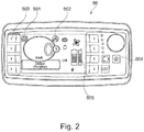
- the instrument panel 5 comprises a display 50, as shown in the figure 2 .
- the display 50 comprises a hybridization status indicator 501, indicating when it is active that the generator set 4 supplies the battery 3, and a status indicator d.
- 'auxiliary 502 which indicates when it is active that an electrical component A is connected to the auxiliary connector 8.
- the instrument panel 5 further comprises a first control button 503 to authorize hybridization, that is to say the supply of battery 3 by the generator 4, and a second control button 504 to authorize the supply of the auxiliary connector 8.
- the display 50 further comprises an indication zone of the charge level 505 of the gas tank 9.
- the display 50 is connected to a control unit 51 of the vehicle, which controls the display 50 and receives information on the state of the vehicle, not detailed here.
- the control unit 51 also communicates with other components of the vehicle via a digital bus, and in particular with the variator 21 and the distribution device 6.
- the device A can typically be a power tool such as a hedge trimmer or a 12V battery charger for recharging batteries.
- the recharging connector 7 is connected to the distribution device 6.
- the distribution device 6 comprises a relay which, on command, connects the recharging connector 7 to the battery 3.
- the relay is supplied by the voltage coming from the extension supply. 40, so that the recharging connector 7 is disconnected when the generator set 4 supplies electricity through the extension supply 40.
- the battery 3 has its own converter 30 to manage the charging of its elements.
- the recharging connector 7 can be connected by the distribution device 6 to the auxiliary connector 8 so that it is thus possible to supply the battery 3 in order to recharge it and to supply power.
- external electrical equipment for example for recharging an electrical device when the battery 3 of the vehicle is charging.
- the distribution device 6 comprises a calculation unit 60 for managing the distribution functions. It also receives the extension power supply 40 from the generator set 4 and connection information 80 from the auxiliary connector 8 indicating the presence of the electrical component A plugged into the auxiliary connector 8.
- the distribution device 6 comprises switching means for connecting the auxiliary connector 8 to the extension power supply 40.
- the auxiliary connector 8 further comprises an indicator 81 indicating the presence of a voltage which supplies the connector 8.
- the gas tank 9 which can be removable is connected to a solenoid valve 91 which makes it possible to connect or not on command a gas network on board the vehicle.
- the gas network then comprises a pressure sensor 92 sending pressure information to the calculation unit 60, then a gas pressure reducer 93 to supply the generator 4.
- the pressure reducer 93 receives a command from the control unit 60. to regulate the gas supply.
- the pressure information is sent over the digital bus for display in the charge level indication area 505.
- the battery 3 When the vehicle is running, without a network power supply connected to the recharging connector 7, the battery 3 provides information on its state of charge on the digital bus and, depending on this level of charge, the computing unit 60 can control the generator 4 so that it supplies energy to the battery 3 via the extension power supply 40. Pressing the second button 504 is received by the computing unit 60 and authorizes the use of the auxiliary connector 8. Auxiliary status indicator 502 remains inactive.
- the computing unit 60 controls the switching means for connecting the auxiliary connector 8 to the extension power supply 40. It also sends information to the display 50 so that the auxiliary status indicator 502 is active. If the generator set 4 is not started, it controls the opening of the solenoid valve 91 to supply the generator set 4 with gas. If the gas pressure is greater than a predetermined threshold, it controls the generator set 4 to obtain its starting beforehand. The generator 4 then supplies energy also to the battery 3, for example in the form of a voltage of 230V in alternating current.
- the connector 8 is supplied with an alternating voltage of between 200V and 240V.
- the distribution device 6 is provided with means for regulating the voltage and with means for detecting the voltage requirements of member A.
- the computing unit 60 can thus control the regulating means for adapt the voltage delivered to the auxiliary connector according to the needs of component A, for example in a voltage range of 6V to 220V, alternating or direct.
- the computing unit 60 When the electrical unit A is disconnected, the computing unit 60 receives the information therefrom. If the battery 3 does not need to be charged any more, the computing unit 60 controls the shutdown of the generator set 4. It also controls the switching means to disconnect the extension power supply 40 and the auxiliary connector 8 It also controls the solenoid valve 91 to cut off the gas supply to the generator 4.
- the battery 3 is supplied by the external source.
- the generator set 4 is running, the external source is disconnected and the battery 3 is supplied by the generator set 4.
- the computing unit 60 When the computing unit 60 receives the information of the presence of an electrical component A connected to the auxiliary connector 8, it sends the vehicle control unit 51 an order to limit the speed of the vehicle below d 'a predetermined threshold. For a land vehicle, this limitation is for example 3 km / h. This limitation order is removed as soon as the electrical component A is disconnected from the auxiliary connector 8.
- the pooling of a generator set is thus achieved in order to extend the autonomy of an electric vehicle and simultaneously to deliver an electric current in order to supply power to portable power tools.
- the generator 4 can receive a speed control. For example, it may have three predetermined speeds, one in reduced mode, providing little power, one in nominal mode, with high power and efficiency, and one in maximum mode, with power at a level higher than the mode. nominal but with an unfavorable return.
- the calculation unit 60 determines and controls the speeds of the generating set 4 as a function of the state of charge of the battery 3, of the demand of the electrical component A and of the engine 2. It takes into account any alarms. from the generator 4 to reduce the speed, for example when a significant heating or another anomaly is detected.
- the invention is not limited to the embodiment which has just been described. It can also be applied to a boat.
- the generator set can be based on a fuel cell.
- the vehicle could be equipped with several auxiliary connectors, outside or inside the vehicle.
- the vehicle according to the invention is an electric vehicle, which does not include a generator.
- the battery 3 is connected to the distribution member 6 by an extension power supply 41.
- the external connector 8 is supplied with power from battery 3 and no longer from generator 4.
- the battery is therefore heavily stressed by the power supply to the vehicle engine and by the external connector.
- the distribution member 6 is therefore designed to limit the use of the external connector according to missions and no longer only according to the gas reserve.
- the operation of the vehicle described above remains the same, except, of course, that the distribution 6 no longer controls the generator set but is designed to control the charge of battery 3.
- a mission is defined as a set of actions to be carried out within a given framework and for a given objective. For example, a mission consists of moving the base to a given point, then performing a task and finally returning to the base. A mission thus includes a distance to be covered on the outward journey, energy consumption, and a return.
- the computer 60 of the distribution member is arranged to calculate and / or store the outward journey, estimate and / or store the return journey and deduce therefrom the quantity of energy necessary to effect this return.
- the distribution member is thus able to limit the energy consumption by the auxiliary connector in order to guarantee the return.
Description
- La présente invention se rapporte à un véhicule électrique ou hybride comportant une batterie d'alimentation d'un moteur électrique pour l'entraînement du véhicule et optionnellement un groupe électrogène pour fournir de l'énergie électrique par une alimentation de prolongement.
- Les contraintes environnementales, la pollution urbaine, les tensions sur le pétrole et les carburants qui en dérivent, les prix des carburants traditionnels incitent aujourd'hui à trouver de nouvelles solutions de mobilité pour diminuer les impacts environnementaux et économiques des déplacements liés à la mobilité des personnes et des marchandises.
- Aussi est-il nécessaire de pouvoir disposer de véhicules peu polluants et disposant d'une autonomie suffisante pour satisfaire les besoins de mobilité tout en diminuant l'impact de ces déplacements.
- Il a déjà été proposé des véhicules électriques comportant une batterie d'alimentation d'un moteur électrique pour la motorisation du véhicule. La batterie est rechargée dans les périodes en dehors de l'utilisation du véhicule, par une connexion de recharge à un réseau électrique. Ces véhicules permettent de maîtriser la pollution au niveau du véhicule. Cependant, leur autonomie est encore relativement modeste.
- Pour augmenter l'autonomie des véhicules électriques, il a été proposé de construire un véhicule hybride en équipant un véhicule électrique d'un prolongateur d'autonomie qui est en pratique un groupe électrogène fournissant un courant de recharge de la batterie. Le groupe électrogène est composé d'un moteur thermique entraînant un générateur électrique. Le moteur thermique peut fonctionner avec divers carburants, comme de l'essence, du gazole ou du gaz.
- Le document
EP-A-0 125 320 décrit un véhicule hybride comportant un moteur électrique d'entraînement du véhicule, une source électrique pour alimenter le moteur par au moins une alimentation de prolongement, comportant au moins un connecteur auxiliaire pour alimenter un organe électrique, et un dispositif de distribution recevant au moins une alimentation de prolongement. L'invention vise à fournir un véhicule hybride à prolongateur d'autonomie ayant des fonctions complémentaires. - Avec ces objectifs en vue, l'invention a pour objet un véhicule électrique ou hybride comportant un moteur électrique d'entraînement du véhicule, une source électrique pour alimenter le moteur par au moins une alimentation de prolongement, le vehicule comportant au moins un connecteur auxiliaire pour alimenter un organe électrique, un dispositif de distribution recevant au moins une alimentation de prolongement et une information de connexion en provenance du connecteur auxiliaire indiquant la présence de l'organe électrique branché dans le connecteur auxiliaire, le dispositif de distribution comportant des moyens de commutation pour connecter alors le connecteur auxiliaire à au moins une des alimentations de prolongement disponibles.
- La source d'alimentation électrique est choisi parmi, une batterie, un groupe électrogène, un connecteur de recharge et sont connectés respectivement au dispositif de distribution par une première alimentation de prolongement, une deuxième alimentation de prolongement et une troisième alimentation de prolongement.
- Grâce à l'invention, on peut disposer à tout moment grâce au connecteur auxiliaire, en tout lieu et sans connexion au réseau de distribution d'électricité, d'une source d'électricité délivrant une puissance électrique capable d'alimenter un organe électrique. Un tel véhicule est destiné en particulier à l'usage des agents qui ont des besoins divers liés à l'utilisation d'équipements électriques ou électroportatifs dans des lieux ouverts, loin d'un réseau électrique fixe accessible. L'usage d'un groupe électrogène est particulièrement avantageux car le même groupe électrogène peut servir d'une part à la prolongation d'autonomie du véhicule électrique et d'autre part à fournir de l'électricité pour un usage externe. Le branchement est établi par exemple directement entre le groupe électrogène ou la batterie et l'organe électrique. Cependant, on peut envisager d'alimenter un convertisseur placé juste en amont du connecteur auxiliaire et qui fournit un type de courant et une tension adaptée vers le connecteur auxiliaire.
- Le dispositif de distribution permet non seulement de puiser l'énergie électrique dans la source la plus disponible, mais également de limiter l'utilisation du connecteur auxiliaire pour préserver les réserves d'énergie.
- De manière avantageuse, lorsque le véhicule est équipé d'un groupe électrogène, celui-ci comporte un réservoir de gaz pour alimenter le groupe électrogène en énergie. La combustion du gaz est peu polluante, même pour une installation immobile.
- Selon un perfectionnement, le réservoir de gaz est amovible. On peut ainsi fournir une recharge de gaz rapidement.
- De manière particulière, le connecteur auxiliaire est accessible depuis l'extérieur du véhicule. Il est ainsi facilement accessible pour des besoins à l'extérieur du véhicule.
- Selon l'invention, le véhicule comporte un connecteur de recharge pour alimenter la batterie par une source de courant extérieure, le dispositif de distribution déconnectant la source de courant extérieure lorsque l'alimentation de prolongement de la batterie est connectée. La priorité est donnée à une alimentation par le groupe électrogène pour la recharge de la batterie. La commutation est réalisée de manière automatique dès que l'électricité est fournie par l'alimentation de prolongement.
- Selon une disposition, le dispositif de distribution délivre une tension alternative au connecteur auxiliaire comprise entre 200V et 240V.
- Selon une autre disposition, le dispositif de distribution comporte des moyens de régulation de la tension et des moyens de détection des besoins en tension de l'organe électrique, les moyens de régulation de la tension étant agencés pour délivrer une tension en fonction des besoins en tension de l'organe électrique détectés par les moyens de détection. On peut ainsi adapter automatiquement la tension délivrée en fonction de l'appareil connecté. Pour cela, le connecteur auxiliaire peut disposer de plusieurs fiches spécifiques adaptées à différentes normes.
- L'invention a aussi pour objet un procédé de gestion d'énergie sur un véhicule hybride ou électrique comportant un moteur électrique d'entraînement du véhicule, et au moins une source électrique parmi, une batterie électrique, un groupe électrogène, caractérisé en ce que au moins une des sources électrique est reliée à un dispositif de distribution par une alimentation de prolongement, le dispositif de distribution connectant en outre une alimentation de prolongement à un connecteur auxiliaire destiné à alimenter un organe électrique lorsque l'organe électrique est branché dans le connecteur auxiliaire. Un connecteur de recharge alimente la batterie par une source de courant extérieure, et le dispositif de distribution déconnecte cette source lorsque l'alimentation de prolongement de la batterie est connectée.
- Selon une disposition particulière, on commande la mise en route du groupe électrogène lorsqu'un organe électrique est connecté au connecteur auxiliaire, et on commande l'arrêt du groupe électrogène lorsqu'aucun organe électrique n'est connecté au connecteur auxiliaire et que la batterie ne sollicite pas de charge. Ainsi le groupe électrogène ne fonctionne que lorsque cela est nécessaire. La présence d'un organe électrique peut être détectée au niveau du connecteur auxiliaire par un renvoi d'information vers le dispositif de distribution.
- Selon un perfectionnement, on commande en outre une arrivée de gaz vers le groupe électrogène pour l'alimenter en énergie de manière synchrone avec le démarrage ou l'arrêt du groupe électrogène. La commande de l'arrivée de gaz permet d'augmenter la sécurité du véhicule.
- Selon un perfectionnement, on ne démarre pas le groupe électrogène si la pression dans le réservoir de gaz est inférieure à un seuil prédéterminé.
- Selon un autre perfectionnement, on limite la vitesse du véhicule au-dessous d'un seuil prédéterminé lorsqu'un organe électrique est connecté au connecteur auxiliaire. Ainsi, il est possible de déplacer le véhicule lorsqu'un organe électrique est connecté. Cependant, la vitesse est limitée pour limiter les risques de la manœuvre et pour alerter également le conducteur du branchement encore opérationnel.
- Selon un autre perfectionnement, le dispositif de distribution comporte des moyens de calcul et des moyens de stockage de données, ledit dispositif de distribution pouvant limiter l'utilisation du connecteur auxiliaire en fonction d'une mission préprogrammée.
- Avantageusement, la programmation d'une mission permet ainsi de limiter l'utilisation du connecteur auxiliaire afin de garantir l'accomplissement de la mission. Une mission est définie au moins en fonction de paramètres choisis parmi : position du vehicule, distance parcourue depuis le dernier rechargement, charge de la batterie, réserve de gaz.
- L'invention sera mieux comprise et d'autres particularités et avantages apparaîtront à la lecture de la description qui va suivre, la description faisant référence aux dessins annexés parmi lesquels :
- la
figure 1 est une vue schématique de dessus d'un véhicule hybride conforme à un mode de réalisation de l'invention ; - la
figure 2 est une vue d'un afficheur placé à l'intérieur du véhicule de lafigure 1 . - Un véhicule hybride selon un mode de réalisation de l'invention est représenté de manière schématique sur la
figure 1 . Le véhicule hybride comporte quatre roues 1, un moteur 2 électrique d'entraînement du véhicule par l'intermédiaire de deux des roues 1 et d'un réducteur 20, une batterie 3 électrique pour alimenter le moteur 2 et un groupe électrogène 4 pour fournir de l'énergie électrique par une premiere alimentation de prolongement 40. Il comporte en outre un tableau de bord 5 à l'intérieur d'un habitacle du véhicule et placé devant des sièges de conducteur et de passager. Le véhicule embarque également un réservoir 9 de gaz en forme de bouteille prévu pour l'alimentation du groupe électrogène 4. - Le véhicule comporte en outre un connecteur de recharge 7 pour recharger la batterie 3 et un connecteur auxiliaire 8 accessible depuis l'extérieur du véhicule pour alimenter un organe électrique A. Un dispositif de distribution 6 est prévu pour gérer des interconnexions entre les dispositifs du véhicule.
- Le dispositif de commande 6 est alimenté par la batterie 3 par une deuxième alimentation de prolongement 41 et peut être également alimenté directement par le connecteur de recharge 7 par une troisième alimentation de prolongement 42. Chacune des alimentations de prolongement 40 à 42 permet d'offrir au dispositif de commande 6 des sources d'alimentation électrique pour alimenter électriquement le connecteur auxiliaire 8. Les alimentations de prolongements 40 à 42 pourront par la suite du texte être désignée par le terme « alimentation de prolongement » sans référence à leur source d'alimentation électrique car leur rôles respectifs sont identiques.
- La batterie 3 est connectée à un variateur 21 auquel elle fournit une tension continue. Le variateur alimente le moteur 2 pour qu'il entraîne les roues 1 dans un sens ou dans l'autre en fonction de commandes en provenance du tableau de bord 5.
- Le tableau de bord 5 comporte un afficheur 50, tel que représenté sur la
figure 2 . Outre l'affichage de fonctions classiques pour un véhicule terrestre, l'afficheur 50 comporte un indicateur d'état d'hybridation 501, indiquant lorsqu'il est actif que le groupe électrogène 4 alimente la batterie 3, et un indicateur d'état d'auxiliaire 502 qui indique lorsqu'il est actif qu'un organe électrique A est connecté au connecteur auxiliaire 8. Le tableau de bord 5 comporte en outre un premier bouton de commande 503 pour autoriser l'hybridation, c'est-à-dire l'alimentation de la batterie 3 par le groupe électrogène 4, et un deuxième bouton de commande 504 pour autoriser l'alimentation du connecteur auxiliaire 8. L'afficheur 50 comporte en outre une zone d'indication du niveau de charge 505 du réservoir 9 de gaz. L'afficheur 50 est relié à une unité de commande 51 du véhicule, qui pilote l'afficheur 50 et reçoit des informations sur l'état du véhicule, non détaillées ici. L'unité de commande 51 communique également avec d'autres composants du véhicule par l'intermédiaire d'un bus numérique, et en particulier avec le variateur 21 et le dispositif de distribution 6. - L'organe A peut être typiquement un outillage électroportatif comme un taille haie ou un chargeur de batterie 12V pour recharger des batteries.
- Le connecteur de recharge 7 est relié au dispositif de distribution 6. Le dispositif de distribution 6 comporte un relais qui connecte sur commande le connecteur de recharge 7 à la batterie 3. Le relais est alimenté par la tension en provenance de l'alimentation de prolongement 40, de telle sorte que le connecteur de recharge 7 est déconnecté lorsque le groupe électrogène 4 fournit de l'électricité par l'alimentation de prolongement 40. La batterie 3 comporte son propre convertisseur 30 pour gérer la charge de ses éléments.
- Selon un mode de réalisation particulier de l'invention, le connecteur de recharge 7 peut être connecté par le dispositif de distribution 6 au connecteur auxiliaire 8 de sorte qu'il est ainsi possible d'alimenter la batterie 3 pour la recharger et d'alimenter un équipement électrique extérieur, par exemple pour recharger un appareil electrique lorsque la batterie 3 du vehicule est en charge.
- Le dispositif de distribution 6 comporte une unité de calcul 60 pour gérer les fonctions de distribution. Il reçoit en outre l'alimentation de prolongement 40 depuis le groupe électrogène 4 et une information de connexion 80 en provenance du connecteur auxiliaire 8 indiquant la présence de l'organe électrique A branché dans le connecteur auxiliaire 8. Le dispositif de distribution 6 comporte des moyens de commutation pour connecter le connecteur auxiliaire 8 à l'alimentation de prolongement 40. Le connecteur auxiliaire 8 comporte en outre un voyant 81 indiquant la présence d'une tension qui alimente le connecteur 8.
- Le réservoir 9 de gaz qui peut être amovible est connecté à une électrovanne 91 qui permet de connecter ou non sur commande un réseau de gaz à bord du véhicule. Le réseau de gaz comporte ensuite un capteur de pression 92 envoyant une information de pression à l'unité de calcul 60, puis un détendeur 93 de gaz pour alimenter le groupe électrogène 4. Le détendeur 93 reçoit une commande de l'unité de commande 60 pour réguler l'arrivée de gaz. L'information de pression est envoyée sur le bus numérique pour qu'elle soit affichée dans la zone d'indication du niveau de charge 505.
- Lorsque le véhicule est en marche, sans alimentation de réseau connecté au connecteur de recharge 7, la batterie 3 donne une information sur son état de charge sur le bus numérique et, en fonction de ce niveau de charge, l'unité de calcul 60 peut commander le groupe électrogène 4 pour qu'il fournisse de l'énergie à la batterie 3 par l'alimentation de prolongement 40. Un appui sur le deuxième bouton 504 est reçu par l'unité de calcul 60 et autorise l'utilisation du connecteur auxiliaire 8. L'indicateur d'état auxiliaire 502 reste inactif.
- Lorsque l'on connecte un organe électrique A dans le connecteur auxiliaire 8, l'information 80 en est reçue par l'unité de calcul 60. Si le groupe électrogène 4 est déjà démarré, et à condition que l'autorisation d'alimenter le connecteur auxiliaire 8 soit donnée par le deuxième bouton 504, l'unité de calcul 60 commande les moyens de commutation pour connecter le connecteur auxiliaire 8 à l'alimentation de prolongement 40. Elle envoie également une information à l'afficheur 50 pour que l'indicateur d'état auxiliaire 502 soit actif. Si le groupe électrogène 4 n'est pas démarré, elle commande l'ouverture de l'électrovanne 91 pour alimenter le groupe électrogène 4 en gaz. Si la pression de gaz est supérieure à un seuil prédéterminé, elle commande le groupe électrogène 4 pour obtenir son démarrage au préalable. Le groupe électrogène 4 fournit alors de l'énergie également à la batterie 3, par exemple sous la forme d'une tension de 230V en courant alternatif.
- L'alimentation du connecteur 8 est réalisée sous une tension alternative comprise entre 200V et 240V. Dans une variante, non représentée, le dispositif de distribution 6 est muni de moyens de régulation de la tension et de moyens de détection des besoins en tension de l'organe A. L'unité de calcul 60 peut ainsi piloter les moyens de régulation pour adapter la tension délivrée au connecteur auxiliaire en fonction des besoins de l'organe A, par exemple dans une plage de tension de 6V à 220V, en alternatif ou en continu.
- Lorsque l'organe électrique A est débranché, l'unité de calcul 60 en reçoit l'information. Si la batterie 3 n'a pas besoin d'être chargée plus, l'unité de calcul 60 pilote l'arrêt du groupe électrogène 4. Elle pilote également les moyens de commutation pour déconnecter l'alimentation de prolongement 40 et le connecteur auxiliaire 8. Elle pilote également l'électrovanne 91 pour couper l'arrivée de gaz au groupe électrogène 4.
- Si le véhicule est connecté à une source de courant extérieure par le connecteur de recharge 7, et que le groupe électrogène 4 est à l'arrêt, la batterie 3 est alimentée par la source extérieure. Par contre, si le groupe électrogène 4 est en marche, la source extérieure est déconnectée et la batterie 3 est alimentée par le groupe électrogène 4.
- Lorsque l'unité de calcul 60 reçoit l'information de la présence d'un organe électrique A branché au connecteur auxiliaire 8, elle envoie à l'unité de commande 51 du véhicule un ordre de limitation de la vitesse du véhicule au-dessous d'un seuil prédéterminé. Pour un véhicule terrestre, cette limitation est par exemple de 3 km/h. Cet ordre de limitation est supprimé dès que l'organe électrique A est déconnecté du connecteur auxiliaire 8.
- On réalise ainsi la mutualisation d'un groupe électrogène pour étendre l'autonomie d'un véhicule électrique et simultanément pour délivrer un courant électrique afin d'alimenter des outillages électroportatifs.
- Dans une variante de l'invention, le groupe électrogène 4 peut recevoir une commande d'allure. Par exemple, il peut comporter trois allures prédéterminées, une de mode réduit, en fournissant peu de puissance, une de mode nominal, avec une puissance et un rendement élevé, et une de mode maximal, avec une puissance d'un niveau supérieur au mode nominal mais avec un rendement peu favorable. L'unité de calcul 60 détermine et pilote les allures du groupe électrogène 4 en fonction de l'état de chargement de la batterie 3, de la demande de l'organe électrique A et du moteur 2. Elle prend en compte d'éventuelles alarmes en provenance du groupe électrogène 4 pour réduire l'allure, par exemple lorsqu'un échauffement important ou une autre anomalie est détecté.
- L'invention n'est pas limitée au mode de réalisation qui vient d'être décrit. Elle peut aussi s'appliquer à un bateau. Le groupe électrogène peut être basé sur une pile à combustible. Le véhicule pourrait être équipé de plusieurs connecteurs auxiliaires, à l'extérieur ou à l'intérieur du véhicule.
- Selon un autre mode de réalisation, le véhicule selon l'invention est un véhicule électrique, qui ne comprend pas de groupe électrogène. Dans ce mode de réalisation, la batterie 3 est reliée à l'organe de distribution 6 par une alimentation de prolongement 41.
- Dans ce mode de fonctionnement, l'alimentation du connecteur extérieur 8 est effectuée à partir de la batterie 3 et non plus à partir du groupe électrogène 4. La batterie est donc fortement sollicitée par l'alimention du moteur du vehicule et par le connecteur extérieur. Selon l'invention, l'organe de distribution 6 est donc agencé pour limiter l'usage du connecteur extérieur selon des missions et non plus uniquement en fonction de la réserve de gaz. Le fonctionnement du véhicule décrit précédemment reste le même, si ce n'est, évidement, que l'organe de distribution 6 ne commande plus le groupe électrogène mais est agencé pour maitriser la charge de la batterie 3.
- Une mission est définie comme un ensemble d'actions à effectuer dans un cadre donné et pour un objectif donné. Une mission est par exemple constituée d'un déplacement de la base jusqu'à un point donné puis l'exécution d'une tache et enfin le retour à la base. Une mission comporte ainsi une distance à parcourir à l'aller, une consommation d'énergie, et un retour.
- Selon l'invention, le calculateur 60 de l'organe de distribution est agencé pour calculer et/ou stocker le trajet aller, estimer et/ou stocker le trajet retour et en déduire la quantité d'énergie nécessaire pour effectuer ce retour. L'organe de distribution est ainsi capable de limiter la consommation d'énergie par le connecteur auxiliaire afin de garantir le retour.
- Parmi les paramètres qui définissent une mission, on peut citer de manière non exhaustive : la position du vehicule en temps réel ou non, la distance parcourue depuis le dernier rechargement, la charge de la batterie, la réserve de gaz
Claims (14)
- Véhicule électrique ou hybride comportant un moteur (2) électrique d'entraînement du véhicule, une source électrique (3, 4) pour alimenter le moteur (2) par au moins une alimentation de prolongement (40, 41, 42), comportant au moins un connecteur auxiliaire (8) pour alimenter un organe électrique (A), un dispositif de distribution (6) recevant au moins une alimentation de prolongement (40, 41, 42) et une information de connexion (80) en provenance du connecteur auxiliaire (8) indiquant la présence de l'organe électrique (A) branché dans le connecteur auxiliaire (8), le dispositif de distribution (6) comportant des moyens de commutation pour connecter alors le connecteur auxiliaire (8) à au moins une des alimentations de prolongement (40, 41, 42) disponibles, et comportant un connecteur de recharge (7) pour alimenter la batterie (3) par une source de courant extérieure, le dispositif de distribution (6) déconnectant la source de courant extérieure lorsque l'alimentation de prolongement (40) de la batterie (3) est connectée.
- Véhicule hybride selon la revendication 1 caractérisé en ce que le véhicule comporte au moins une source d'alimentation électrique parmi, une batterie (3), un groupe électrogène (4), un connecteur de recharge (7) connectés respectivement au dispositif de distribution (6) par une première alimentation de prolongement (40), une deuxième alimentation de prolongement (41) et une troisième alimentation de prolongement (42).
- Véhicule selon la revendication 1, caractérisé en ce qu'il comporte un réservoir (9) de gaz pour alimenter le groupe électrogène (4) en énergie.
- Véhicule selon la revendication 3, dans lequel le réservoir (9) de gaz est amovible.
- Véhicule selon l'une des revendications 1 à 3, dans lequel le connecteur auxiliaire (8) est accessible depuis l'extérieur du véhicule.
- Véhicule selon l'une des revendications 1 à 5, dans lequel le dispositif de distribution (6) délivre une tension alternative au connecteur auxiliaire (8) comprise entre 200V et 240V.
- Véhicule selon l'une des revendication 1 à 5 dans lequel le dispositif de distribution comporte des moyens de régulation de la tension et des moyens de détection des besoins en tension de l'organe électrique (A), les moyens de régulation de la tension étant agencés pour délivrer une tension en fonction des besoins en tension de l'organe électrique (A) détectés par les moyens de détection.
- Procédé de gestion d'énergie sur un véhicule hybride ou électrique comportant un moteur (2) électrique d'entraînement du véhicule, et au moins une source électrique parmi, une batterie (3) électrique, un groupe électrogène (4), tel que au moins une des sources électrique est reliée à un dispositif de distribution (6) par une alimentation de prolongement (40, 41, 42), et en ce qu'un connecteur de recharge (7) alimente la batterie (3) par une source de courant extérieure, le dispositif de distribution (6) déconnectant la source de courant extérieure lorsque l'alimentation de prolongement (40) de la batterie (3) est connectée et connectant en outre une alimentation de prolongement (40) à un connecteur auxiliaire (8) destiné à alimenter un organe électrique (A) lorsque l'organe électrique (A) est branché dans le connecteur auxiliaire (8).
- Procédé selon la revendication 8, selon lequel on commande la mise en route du groupe électrogène (4) lorsqu'un organe électrique (A) est connecté au connecteur auxiliaire (8), et on commande l'arrêt du groupe électrogène (4) lorsqu'aucun organe électrique (A) n'est connecté au connecteur auxiliaire (8) et que la batterie (3) ne sollicite pas de charge.
- Procédé selon la revendication 9, selon lequel on commande en outre une arrivée de gaz vers le groupe électrogène (4) pour l'alimenter en énergie de manière synchrone avec le démarrage ou l'arrêt du groupe électrogène (4).
- Procédé selon la revendication 10, selon lequel on ne démarre pas le groupe électrogène (4) si la pression dans le réservoir (9) de gaz est inférieure à un seuil prédéterminé.
- Procédé selon l'une des revendications 9 à 11, selon lequel on limite la vitesse du véhicule au-dessous d'un seuil prédéterminé lorsqu'un organe électrique (A) est connecté au connecteur auxiliaire (8).
- Procédé selon l'une des revendications 9 à 12 dans lequel le dispositif de distribution (6) comporte des moyens de calcul (60) et des moyens de stockage de données, ledit dispositif de distribution (6) pouvant limiter l'utilisation du connecteur auxiliaire en fonction d'une mission préprogrammée.
- Procédé selon la revendication 13 dans lequel la mission est définie au moins en fonction de paramètres choisis parmi : position du véhicule, distance parcourue depuis le dernier rechargement, charge de la batterie, réserve de gaz.
Applications Claiming Priority (3)
| Application Number | Priority Date | Filing Date | Title |
|---|---|---|---|
| FR1363478A FR3015378B1 (fr) | 2013-12-23 | 2013-12-23 | Vehicule hybride comportant un groupe electrogene |
| FR1452928A FR3015391B1 (fr) | 2013-12-23 | 2014-04-02 | Vehicule comportant un groupe electrogene |
| PCT/FR2014/053475 WO2015097387A1 (fr) | 2013-12-23 | 2014-12-19 | Véhicule comportant un groupe électrogène |
Publications (2)
| Publication Number | Publication Date |
|---|---|
| EP3086972A1 EP3086972A1 (fr) | 2016-11-02 |
| EP3086972B1 true EP3086972B1 (fr) | 2021-03-10 |
Family
ID=50231412
Family Applications (1)
| Application Number | Title | Priority Date | Filing Date |
|---|---|---|---|
| EP14835482.2A Active EP3086972B1 (fr) | 2013-12-23 | 2014-12-19 | Véhicule comportant un groupe électrogène |
Country Status (4)
| Country | Link |
|---|---|
| EP (1) | EP3086972B1 (fr) |
| FR (2) | FR3015378B1 (fr) |
| LT (1) | LT3086972T (fr) |
| WO (1) | WO2015097387A1 (fr) |
Family Cites Families (6)
| Publication number | Priority date | Publication date | Assignee | Title |
|---|---|---|---|---|
| EP0125320B1 (fr) * | 1983-04-14 | 1990-10-03 | Götz Dipl.-Phys. Heidelberg | Utilisation d'un véhicule comme groupe électrogène autonome pour la consommation externe de courant |
| DE10107023A1 (de) * | 2001-02-15 | 2002-08-22 | Volkswagen Ag | Kraftfahrzeug-Energieversorgungseinheit |
| DE10242619A1 (de) * | 2002-09-13 | 2004-03-18 | Still Gmbh | Flurförderzeug |
| DE102007051362A1 (de) * | 2007-10-26 | 2009-04-30 | Enerday Gmbh | Kraftfahrzeug mit Schnittstelle zum Versorgen eines fahrzeugunabhängigen Stromverbrauchers |
| JP4438887B1 (ja) * | 2008-09-26 | 2010-03-24 | トヨタ自動車株式会社 | 電動車両及び電動車両の充電制御方法 |
| DE102012001174A1 (de) * | 2012-01-24 | 2013-07-25 | Volkswagen Aktiengesellschaft | Verfahren zur Steuerung eines Hybridantriebs für ein Fahrzeug und Hybridantrieb |
-
2013
- 2013-12-23 FR FR1363478A patent/FR3015378B1/fr not_active Expired - Fee Related
-
2014
- 2014-04-02 FR FR1452928A patent/FR3015391B1/fr not_active Expired - Fee Related
- 2014-12-19 WO PCT/FR2014/053475 patent/WO2015097387A1/fr active Application Filing
- 2014-12-19 EP EP14835482.2A patent/EP3086972B1/fr active Active
- 2014-12-19 LT LTEP14835482.2T patent/LT3086972T/lt unknown
Non-Patent Citations (1)
| Title |
|---|
| None * |
Also Published As
| Publication number | Publication date |
|---|---|
| FR3015378A1 (fr) | 2015-06-26 |
| LT3086972T (lt) | 2021-07-26 |
| WO2015097387A1 (fr) | 2015-07-02 |
| FR3015391A1 (fr) | 2015-06-26 |
| EP3086972A1 (fr) | 2016-11-02 |
| FR3015378B1 (fr) | 2016-02-05 |
| FR3015391B1 (fr) | 2016-02-05 |
Similar Documents
| Publication | Publication Date | Title |
|---|---|---|
| EP2207697B1 (fr) | Procede de gestion de l'energie dans un vehicule automobile | |
| EP2385755B1 (fr) | Tondeuse electrique a conducteur porte et a alimentation autonome en fonctionnement | |
| EP2074005B1 (fr) | Procédé de gestion d'énergie d'une chaîne de traction d'un véhicule hybride et véhicule hybride | |
| FR3006669A1 (fr) | Dispositif d’alimentation electrique pour aeronef a propulsion electrique | |
| EP1410481B1 (fr) | Systeme de gestion de l'energie electrique d'un vehicule hybride | |
| EP2372864B1 (fr) | Système autonome de motorisation | |
| WO2014118476A1 (fr) | Dispositif d'alimentation electrique d'un reseau de bord de vehicule automobile hybride | |
| EP3771059A1 (fr) | Procédé d'alimentation électrique d'un réseau électrique et architecture électrique | |
| EP3086972B1 (fr) | Véhicule comportant un groupe électrogène | |
| CA3044731A1 (fr) | Procede et systeme de gestion d'un vehicule electrique ou hybride rechargeable | |
| EP2589131B1 (fr) | Alimentation d'un reseau de bord d'un vehicule automobile | |
| EP3323668A1 (fr) | Système et procédé de commande d'alimentation électrique sans interruption domestique connectée à un véhicule électrique ou hybride | |
| FR3018007A1 (fr) | Dispositif pour vehicule hybride de recharge d'une batterie basse tension a partir du reseau tres basse tension | |
| FR2979293A1 (fr) | Dispositif d'alimentation en energie electrique notamment pour un vehicule automobile. | |
| EP3342747B1 (fr) | Structure d'alimentation pour chariot élévateur | |
| WO2022200497A1 (fr) | Dispositif autonome d'alimentation électrique, notamment pour charger une batterie | |
| FR2921590A1 (fr) | Dispositif et procede d'alimentation electrique multi-tension pour vehicules hybrides | |
| EP4195335A1 (fr) | Système de gestion thermique d'un système hybride pile à combustible batterie rechargeable | |
| FR2941066A1 (fr) | Dispositif d'assistance electrique destine a un vehicule hybride | |
| FR3019395A1 (fr) | Systeme d'alimentation d'une machine electrique de traction d'un vehicule hybride, pour la recharge de sa batterie par un reseau exterieur | |
| EP2965398A1 (fr) | Dispositif d'alimentation commute pour le réseau de bord d'un véhicule automobile | |
| WO2000032438A1 (fr) | Bloc generateur d'energie intelligent pour maintenir chargees les batteries d'un vehicule electrique | |
| FR2901071A1 (fr) | Systeme et procede de production d'energie electrique pour vehicule automobile a moteur de traction electrique | |
| FR3009247A1 (fr) | Vehicule atelier autonome |
Legal Events
| Date | Code | Title | Description |
|---|---|---|---|
| PUAI | Public reference made under article 153(3) epc to a published international application that has entered the european phase |
Free format text: ORIGINAL CODE: 0009012 |
|
| 17P | Request for examination filed |
Effective date: 20160701 |
|
| AK | Designated contracting states |
Kind code of ref document: A1 Designated state(s): AL AT BE BG CH CY CZ DE DK EE ES FI FR GB GR HR HU IE IS IT LI LT LU LV MC MK MT NL NO PL PT RO RS SE SI SK SM TR |
|
| AX | Request for extension of the european patent |
Extension state: BA ME |
|
| RAP1 | Party data changed (applicant data changed or rights of an application transferred) |
Owner name: FRANCE CRAFT Owner name: ENGIE |
|
| DAX | Request for extension of the european patent (deleted) | ||
| GRAP | Despatch of communication of intention to grant a patent |
Free format text: ORIGINAL CODE: EPIDOSNIGR1 |
|
| STAA | Information on the status of an ep patent application or granted ep patent |
Free format text: STATUS: GRANT OF PATENT IS INTENDED |
|
| RIC1 | Information provided on ipc code assigned before grant |
Ipc: B60K 15/07 20060101ALI20200904BHEP Ipc: B60K 6/46 20071001AFI20200904BHEP Ipc: B60W 10/18 20120101ALI20200904BHEP Ipc: B60L 1/00 20060101ALI20200904BHEP Ipc: B60W 10/30 20060101ALI20200904BHEP Ipc: B60W 10/08 20060101ALI20200904BHEP Ipc: B60W 10/06 20060101ALI20200904BHEP Ipc: B60W 10/26 20060101ALI20200904BHEP |
|
| INTG | Intention to grant announced |
Effective date: 20200928 |
|
| GRAS | Grant fee paid |
Free format text: ORIGINAL CODE: EPIDOSNIGR3 |
|
| GRAA | (expected) grant |
Free format text: ORIGINAL CODE: 0009210 |
|
| STAA | Information on the status of an ep patent application or granted ep patent |
Free format text: STATUS: THE PATENT HAS BEEN GRANTED |
|
| AK | Designated contracting states |
Kind code of ref document: B1 Designated state(s): AL AT BE BG CH CY CZ DE DK EE ES FI FR GB GR HR HU IE IS IT LI LT LU LV MC MK MT NL NO PL PT RO RS SE SI SK SM TR |
|
| REG | Reference to a national code |
Ref country code: GB Ref legal event code: FG4D Free format text: NOT ENGLISH |
|
| REG | Reference to a national code |
Ref country code: AT Ref legal event code: REF Ref document number: 1369438 Country of ref document: AT Kind code of ref document: T Effective date: 20210315 Ref country code: CH Ref legal event code: EP |
|
| REG | Reference to a national code |
Ref country code: DE Ref legal event code: R096 Ref document number: 602014075626 Country of ref document: DE |
|
| REG | Reference to a national code |
Ref country code: IE Ref legal event code: FG4D Free format text: LANGUAGE OF EP DOCUMENT: FRENCH |
|
| REG | Reference to a national code |
Ref country code: SE Ref legal event code: TRGR |
|
| PG25 | Lapsed in a contracting state [announced via postgrant information from national office to epo] |
Ref country code: FI Free format text: LAPSE BECAUSE OF FAILURE TO SUBMIT A TRANSLATION OF THE DESCRIPTION OR TO PAY THE FEE WITHIN THE PRESCRIBED TIME-LIMIT Effective date: 20210310 Ref country code: HR Free format text: LAPSE BECAUSE OF FAILURE TO SUBMIT A TRANSLATION OF THE DESCRIPTION OR TO PAY THE FEE WITHIN THE PRESCRIBED TIME-LIMIT Effective date: 20210310 Ref country code: GR Free format text: LAPSE BECAUSE OF FAILURE TO SUBMIT A TRANSLATION OF THE DESCRIPTION OR TO PAY THE FEE WITHIN THE PRESCRIBED TIME-LIMIT Effective date: 20210611 Ref country code: BG Free format text: LAPSE BECAUSE OF FAILURE TO SUBMIT A TRANSLATION OF THE DESCRIPTION OR TO PAY THE FEE WITHIN THE PRESCRIBED TIME-LIMIT Effective date: 20210610 |
|
| REG | Reference to a national code |
Ref country code: AT Ref legal event code: MK05 Ref document number: 1369438 Country of ref document: AT Kind code of ref document: T Effective date: 20210310 |
|
| REG | Reference to a national code |
Ref country code: NL Ref legal event code: MP Effective date: 20210310 |
|
| REG | Reference to a national code |
Ref country code: NO Ref legal event code: T2 Effective date: 20210310 |
|
| PG25 | Lapsed in a contracting state [announced via postgrant information from national office to epo] |
Ref country code: RS Free format text: LAPSE BECAUSE OF FAILURE TO SUBMIT A TRANSLATION OF THE DESCRIPTION OR TO PAY THE FEE WITHIN THE PRESCRIBED TIME-LIMIT Effective date: 20210310 |
|
| PG25 | Lapsed in a contracting state [announced via postgrant information from national office to epo] |
Ref country code: NL Free format text: LAPSE BECAUSE OF FAILURE TO SUBMIT A TRANSLATION OF THE DESCRIPTION OR TO PAY THE FEE WITHIN THE PRESCRIBED TIME-LIMIT Effective date: 20210310 |
|
| PG25 | Lapsed in a contracting state [announced via postgrant information from national office to epo] |
Ref country code: SM Free format text: LAPSE BECAUSE OF FAILURE TO SUBMIT A TRANSLATION OF THE DESCRIPTION OR TO PAY THE FEE WITHIN THE PRESCRIBED TIME-LIMIT Effective date: 20210310 Ref country code: AT Free format text: LAPSE BECAUSE OF FAILURE TO SUBMIT A TRANSLATION OF THE DESCRIPTION OR TO PAY THE FEE WITHIN THE PRESCRIBED TIME-LIMIT Effective date: 20210310 Ref country code: EE Free format text: LAPSE BECAUSE OF FAILURE TO SUBMIT A TRANSLATION OF THE DESCRIPTION OR TO PAY THE FEE WITHIN THE PRESCRIBED TIME-LIMIT Effective date: 20210310 Ref country code: CZ Free format text: LAPSE BECAUSE OF FAILURE TO SUBMIT A TRANSLATION OF THE DESCRIPTION OR TO PAY THE FEE WITHIN THE PRESCRIBED TIME-LIMIT Effective date: 20210310 |
|
| PG25 | Lapsed in a contracting state [announced via postgrant information from national office to epo] |
Ref country code: SK Free format text: LAPSE BECAUSE OF FAILURE TO SUBMIT A TRANSLATION OF THE DESCRIPTION OR TO PAY THE FEE WITHIN THE PRESCRIBED TIME-LIMIT Effective date: 20210310 Ref country code: PT Free format text: LAPSE BECAUSE OF FAILURE TO SUBMIT A TRANSLATION OF THE DESCRIPTION OR TO PAY THE FEE WITHIN THE PRESCRIBED TIME-LIMIT Effective date: 20210712 Ref country code: PL Free format text: LAPSE BECAUSE OF FAILURE TO SUBMIT A TRANSLATION OF THE DESCRIPTION OR TO PAY THE FEE WITHIN THE PRESCRIBED TIME-LIMIT Effective date: 20210310 Ref country code: ES Free format text: LAPSE BECAUSE OF FAILURE TO SUBMIT A TRANSLATION OF THE DESCRIPTION OR TO PAY THE FEE WITHIN THE PRESCRIBED TIME-LIMIT Effective date: 20210310 Ref country code: IS Free format text: LAPSE BECAUSE OF FAILURE TO SUBMIT A TRANSLATION OF THE DESCRIPTION OR TO PAY THE FEE WITHIN THE PRESCRIBED TIME-LIMIT Effective date: 20210710 |
|
| REG | Reference to a national code |
Ref country code: DE Ref legal event code: R097 Ref document number: 602014075626 Country of ref document: DE |
|
| PLBE | No opposition filed within time limit |
Free format text: ORIGINAL CODE: 0009261 |
|
| STAA | Information on the status of an ep patent application or granted ep patent |
Free format text: STATUS: NO OPPOSITION FILED WITHIN TIME LIMIT |
|
| PG25 | Lapsed in a contracting state [announced via postgrant information from national office to epo] |
Ref country code: DK Free format text: LAPSE BECAUSE OF FAILURE TO SUBMIT A TRANSLATION OF THE DESCRIPTION OR TO PAY THE FEE WITHIN THE PRESCRIBED TIME-LIMIT Effective date: 20210310 Ref country code: AL Free format text: LAPSE BECAUSE OF FAILURE TO SUBMIT A TRANSLATION OF THE DESCRIPTION OR TO PAY THE FEE WITHIN THE PRESCRIBED TIME-LIMIT Effective date: 20210310 |
|
| PGFP | Annual fee paid to national office [announced via postgrant information from national office to epo] |
Ref country code: LT Payment date: 20211117 Year of fee payment: 8 Ref country code: NO Payment date: 20211118 Year of fee payment: 8 Ref country code: DE Payment date: 20211117 Year of fee payment: 8 Ref country code: RO Payment date: 20211220 Year of fee payment: 8 Ref country code: SE Payment date: 20211119 Year of fee payment: 8 Ref country code: FR Payment date: 20211118 Year of fee payment: 8 |
|
| 26N | No opposition filed |
Effective date: 20211213 |
|
| PG25 | Lapsed in a contracting state [announced via postgrant information from national office to epo] |
Ref country code: SI Free format text: LAPSE BECAUSE OF FAILURE TO SUBMIT A TRANSLATION OF THE DESCRIPTION OR TO PAY THE FEE WITHIN THE PRESCRIBED TIME-LIMIT Effective date: 20210310 |
|
| PGFP | Annual fee paid to national office [announced via postgrant information from national office to epo] |
Ref country code: LV Payment date: 20211117 Year of fee payment: 8 Ref country code: IT Payment date: 20211117 Year of fee payment: 8 |
|
| PG25 | Lapsed in a contracting state [announced via postgrant information from national office to epo] |
Ref country code: IS Free format text: LAPSE BECAUSE OF FAILURE TO SUBMIT A TRANSLATION OF THE DESCRIPTION OR TO PAY THE FEE WITHIN THE PRESCRIBED TIME-LIMIT Effective date: 20210710 |
|
| PG25 | Lapsed in a contracting state [announced via postgrant information from national office to epo] |
Ref country code: MC Free format text: LAPSE BECAUSE OF FAILURE TO SUBMIT A TRANSLATION OF THE DESCRIPTION OR TO PAY THE FEE WITHIN THE PRESCRIBED TIME-LIMIT Effective date: 20210310 |
|
| REG | Reference to a national code |
Ref country code: CH Ref legal event code: PL |
|
| GBPC | Gb: european patent ceased through non-payment of renewal fee |
Effective date: 20211219 |
|
| REG | Reference to a national code |
Ref country code: BE Ref legal event code: MM Effective date: 20211231 |
|
| PG25 | Lapsed in a contracting state [announced via postgrant information from national office to epo] |
Ref country code: LU Free format text: LAPSE BECAUSE OF NON-PAYMENT OF DUE FEES Effective date: 20211219 Ref country code: IE Free format text: LAPSE BECAUSE OF NON-PAYMENT OF DUE FEES Effective date: 20211219 Ref country code: GB Free format text: LAPSE BECAUSE OF NON-PAYMENT OF DUE FEES Effective date: 20211219 |
|
| PG25 | Lapsed in a contracting state [announced via postgrant information from national office to epo] |
Ref country code: BE Free format text: LAPSE BECAUSE OF NON-PAYMENT OF DUE FEES Effective date: 20211231 |
|
| PG25 | Lapsed in a contracting state [announced via postgrant information from national office to epo] |
Ref country code: LI Free format text: LAPSE BECAUSE OF NON-PAYMENT OF DUE FEES Effective date: 20211231 Ref country code: CH Free format text: LAPSE BECAUSE OF NON-PAYMENT OF DUE FEES Effective date: 20211231 |
|
| PG25 | Lapsed in a contracting state [announced via postgrant information from national office to epo] |
Ref country code: HU Free format text: LAPSE BECAUSE OF FAILURE TO SUBMIT A TRANSLATION OF THE DESCRIPTION OR TO PAY THE FEE WITHIN THE PRESCRIBED TIME-LIMIT; INVALID AB INITIO Effective date: 20141219 |
|
| PG25 | Lapsed in a contracting state [announced via postgrant information from national office to epo] |
Ref country code: CY Free format text: LAPSE BECAUSE OF FAILURE TO SUBMIT A TRANSLATION OF THE DESCRIPTION OR TO PAY THE FEE WITHIN THE PRESCRIBED TIME-LIMIT Effective date: 20210310 |
|
| REG | Reference to a national code |
Ref country code: DE Ref legal event code: R119 Ref document number: 602014075626 Country of ref document: DE |
|
| REG | Reference to a national code |
Ref country code: LT Ref legal event code: MM4D Effective date: 20221219 |
|
| REG | Reference to a national code |
Ref country code: NO Ref legal event code: MMEP |
|
| PG25 | Lapsed in a contracting state [announced via postgrant information from national office to epo] |
Ref country code: RO Free format text: LAPSE BECAUSE OF NON-PAYMENT OF DUE FEES Effective date: 20221219 Ref country code: LV Free format text: LAPSE BECAUSE OF NON-PAYMENT OF DUE FEES Effective date: 20221219 |
|
| REG | Reference to a national code |
Ref country code: SE Ref legal event code: EUG |
|
| PG25 | Lapsed in a contracting state [announced via postgrant information from national office to epo] |
Ref country code: SE Free format text: LAPSE BECAUSE OF NON-PAYMENT OF DUE FEES Effective date: 20221220 Ref country code: NO Free format text: LAPSE BECAUSE OF NON-PAYMENT OF DUE FEES Effective date: 20221231 Ref country code: DE Free format text: LAPSE BECAUSE OF NON-PAYMENT OF DUE FEES Effective date: 20230701 |
|
| PG25 | Lapsed in a contracting state [announced via postgrant information from national office to epo] |
Ref country code: LT Free format text: LAPSE BECAUSE OF NON-PAYMENT OF DUE FEES Effective date: 20221219 Ref country code: FR Free format text: LAPSE BECAUSE OF NON-PAYMENT OF DUE FEES Effective date: 20221231 |
|
| PG25 | Lapsed in a contracting state [announced via postgrant information from national office to epo] |
Ref country code: IT Free format text: LAPSE BECAUSE OF NON-PAYMENT OF DUE FEES Effective date: 20221219 |
|
| PG25 | Lapsed in a contracting state [announced via postgrant information from national office to epo] |
Ref country code: MK Free format text: LAPSE BECAUSE OF FAILURE TO SUBMIT A TRANSLATION OF THE DESCRIPTION OR TO PAY THE FEE WITHIN THE PRESCRIBED TIME-LIMIT Effective date: 20210310 |