EP2385755B1 - Elektrischer rasenmäher mit fahrer und mit autonom arbeitender stromversorgung - Google Patents
Elektrischer rasenmäher mit fahrer und mit autonom arbeitender stromversorgung Download PDFInfo
- Publication number
- EP2385755B1 EP2385755B1 EP10706285A EP10706285A EP2385755B1 EP 2385755 B1 EP2385755 B1 EP 2385755B1 EP 10706285 A EP10706285 A EP 10706285A EP 10706285 A EP10706285 A EP 10706285A EP 2385755 B1 EP2385755 B1 EP 2385755B1
- Authority
- EP
- European Patent Office
- Prior art keywords
- mower
- electric
- motors
- ride
- motor
- Prior art date
- Legal status (The legal status is an assumption and is not a legal conclusion. Google has not performed a legal analysis and makes no representation as to the accuracy of the status listed.)
- Active
Links
Images

Classifications
-
- A—HUMAN NECESSITIES
- A01—AGRICULTURE; FORESTRY; ANIMAL HUSBANDRY; HUNTING; TRAPPING; FISHING
- A01D—HARVESTING; MOWING
- A01D69/00—Driving mechanisms or parts thereof for harvesters or mowers
- A01D69/02—Driving mechanisms or parts thereof for harvesters or mowers electric
Definitions
- the present invention relates to the field of mowers, especially electric lawn mowers, and relates to a mower ride, electric and self-powered operation.
- towed or pushed merchantable mowers are not suitable for large surfaces, for which ride-on mowers (more commonly known as riding mowers) are preferred.
- the present invention is intended in particular to overcome the aforementioned drawbacks, by proposing an electric ride mower with a constitution and performance substantially identical to those of an equivalent thermal model and having improved comfort of use and a increased operational safety, in particular by limiting power consumption, limiting current peaks that are detrimental to autonomy and optimizing the lifetime of the electrical storage means.
- the subject of the present invention is an electric mower with a self-driving conductor and an operating autonomous power supply, essentially comprising a chassis mounted on rolling means, at least some of which are connected to a steering means, and supporting a means for the user and at least one cutting device with one or more cutting members, said driving mower further comprising, on the one hand, an onboard electrical energy storage means, such as at least one battery or at least one accumulator, d.
- At least one first electric drive motor moving said riding mower and finally at least one second electric motor driving said at least one cutting member, riding mower characterized in that each of the electric motors is controlled by an associated drive, adapted to the type of engine considered, as a function of control signals delivered by corresponding control members and status signals and / or provided by corresponding sensor and / or detector means, the states and / or modes of operation of said motors being also at least partially interdependent and dependent on the state of charge of the electrical energy storage means, the operation management the different motors being carried out either by a specific electronic processing unit, or by electronic processing units integrated with the different variators and co-operating in a complementary manner, this management being carried out on the basis of a predetermined programming and taking into account the various signals supra.
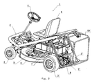
- the mower 1 with an electric powered conductor has a general structure substantially similar to that of a mower with a thermal reach conductor and essentially comprises a chassis 2 mounted on rolling means 3, 3 ', at least some of which are connected to a means 4, and supporting a seating means (seat) 5 for the user and at least one cutting device 6 with one or more cutting members (blades) 6 '.
- This mower 1 electric conductor further comprises, on the one hand, an onboard means 7 for accumulating electrical energy, such as at least one battery or at least one accumulator (for example, several lead-acid batteries connected in series and / or in parallel), on the other hand, at least a first electric motor 8 driving in displacement of said mower 1 and, finally, at least a second electric motor 9 for driving said at least one cutting member 6 '.
- an onboard means 7 for accumulating electrical energy such as at least one battery or at least one accumulator (for example, several lead-acid batteries connected in series and / or in parallel)
- at least a first electric motor 8 driving in displacement of said mower 1
- at least a second electric motor 9 for driving said at least one cutting member 6 '.
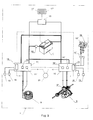
- each of the electric motors 8, 9 is controlled by an associated variator 10, 11, adapted to the type of motor 8, 9 considered, as a function of control signals delivered by control members 12, 12 ' , 13, 20 corresponding and status signals and / or measurement provided by corresponding sensor and / or sensor members 14, 14 ', 18, 19, the states and / or modes of operation of said motors 8, 9 being also at least partially interdependent and dependent on the state of charge of the means 7 of accumulation of electrical energy, the management of the operation of the various motors 8, 9 being carried out either by a specific electronic processing unit, or by electronic units of processing 10 ', 11' integrated in the various variators 10, 11 and cooperating in a complementary manner, this management being performed on the basis of a predetermined programming and taking into account the different if mentioned above.
- the mower 1 reports means for an optimized management of its operation, the management mode can be at least partially predefined by prior programming.
- the electric motors 8, 9 may be of different types, namely direct current, synchronous or asynchronous, the motors 8 possibly being of a different type than the motors 9, this depending on the cost, power requirements, operational priorities and / or specificities of use.
- the motor 8 may be of the asynchronous type and the motor 9 of the synchronous type (in particular if only one driving speed of the one or more cutting members is envisaged).
- the drives 10 and 11 used are of course chosen according to the type of the motors 8, 9, the power to be supplied to the latter, and, where appropriate, particular operating specificities.
- these drives 10, 11 may be of the vector control type.
- These drives can be in the form of electronic / electrotechnical modules mounted in independent boxes or grouped together in the same housing.
- the accumulation means 7 is positioned centrally relative to the frame 2 and relatively low (for example substantially under the seat 5) and consists of several elements placed in series, their cumulative capacity being determined according to the desired mowing autonomy (for example 1500 m 2 ).
- the loading of the accumulation means 7 can be done conventionally by means of a charger connected to the sector, but alternative charging solutions of the photovoltaic or wind type can also be envisaged (renewable energy sources installed at the local level of storage of the lawn mower 1), possibly additionally, for the leveling loadings.
- an automatic limitation of the maximum speed of displacement is achieved when said at least one cutting device 6 is put into operation, the mechanical stroke of the one or more members 12, 12 'of displacement control remaining preferably unchanged, thereby maintaining a constant range of motion for the driver.
- the maximum advance speed can be 8 km / h and in mowing mode the maximum feed speed can be set at 5 km / h.
- the maximum speed of the latter is automatically reduced to 5 km / h.
- the maximum travel speed can be automatically increased if the mowing function is cut off.
- the displacement control members 12, 12 ' consist of two pedals (for example tilting or pivoting) associated with a common potentiometer or each with a corresponding potentiometer 12 ", delivering a control signal which is a function of the position of the pedal or associated pedal 12, 12 ', a first pedal 12 controlling the moving forward and the second pedal 12 'controlling the movement in reverse.
- the ride-on mower 1 may also comprise a displacement speed regulation means, preferentially integrated with the variator associated with the engine (s) under consideration, said regulating means being controlled by an organ 13 activation and deactivation maneuverable by the user (for example a push button implusion).
- This regulating means thus makes it possible to limit sudden variations and peaks in absorbed power, and furthermore ensures user comfort for the user over long distances.
- the ride-on mower 1 comprises, possibly integrated in the variators 10, 11, sensors 14, 14 'for measuring the inrush currents of the various motors 8, 9, each of the measured values and their sum being compared with respectively corresponding upper limit values, the excess of which results in a reduction of the rotational speeds, or even a stop, of the motor 8 or 9 concerned or all of said motors 8, 9.
- T3 40 volts.
- the drives 10, 11 have a reversible operation (by integrating, for example, reversible inverters) and are associated with respective capacitors 15, thus making it possible to absorb the electrical energy delivered. by the motors 8, 9 associated when they operate as generators, to send it in a controlled manner to the accumulation means 7 and / or to one or more other motors 8, 9.
- This arrangement not only allows recovery of beneficial energy in certain operating contexts (downward sloping movement, braking phase, during deceleration of the member or cutting members 6 'after cutting off the engine power supply 9), but also to avoid undesirable heating of the electronic components and circuits resulting from the unused energy converted into calories.
- the mower driver 1 may comprise at least one AC source 16, possibly with different adjustable voltages, connected to the means 7 of accumulation of electrical energy, integrating at least one chopper circuit and provided with at least one external connection device, such as a plug and / or a cable 17.
- This source 16 may in particular be adapted to provide, depending on the user's choice, alternating voltages of 48 volts, 110 volts and 230 volts.
- the riding mower 1 thus constitutes an automotive generator for locally powering various tools or electrical equipment, especially used in green areas, such as secateurs, saws, pumps, hedge trimmers, trimmers or the like.
- the ride-on mower may also comprise at least one cable reel 17 ', one of the ends of said cable 17 being preferably connected, possibly removably, to the source AC 16 on board.
- the specific processing unit or the complementary processing units 10 ', 11' permanently produce a a real-time diagnostic function of the state and operating mode of the mower 1 and its various functions, based on the signals supplied by the various sensors and detectors, the results of said diagnosis being visualized, possibly coded, through one or more display means 21, comprising for example at least one liquid crystal display, which can be easily apprehended by the user in the driving position .
- the displacement control members are automatically positioned in neutral (verification of this provision during diagnosis).
- the rolling means are composed of two front steering wheels 3 and two rear driving wheels 3 ', the cutting member 6' being driven directly by the corresponding motor 9 and the driving wheels 3 'being driven through a differential gearing 3 "by the corresponding motor 8.
- the rolling means are composed of two idlers and two driving wheels each driven by a corresponding clean engine, the relative speeds of rotation. the latter being regulated by the steering means (the direction of movement results from the speed differential between the two drive wheels).
- the riding mower 1 may alternatively comprise a plurality of cutting devices 6 with one or more cutting members 6' or a single device 6 with a plurality of cutting members 6 ', such that it comprises at least two cutting members driven by at least one corresponding motor and mounted mutually shifted transversely.
- the present invention also relates to a method of controlling the operation of a mower electric conductor self-powered operation.
- This mower 1 essentially comprises a frame 2 mounted on rolling means 3, 3 ', at least some of which are connected to a steering means 4, and supporting a seating means 5 for the user and at least one section 6 with one or more cutting members 6 ', this mower 1 further comprising, on the one hand, an onboard means 7 for storing electrical energy, such as at least one battery or at least one at least one accumulator, on the other hand, at least a first electric motor 8 driving in displacement of said mower and, finally, at least a second electric motor 9 for driving said at least one cutting member.
- an onboard means 7 for storing electrical energy, such as at least one battery or at least one at least one accumulator, on the other hand, at least a first electric motor 8 driving in displacement of said mower and, finally, at least a second electric motor 9 for driving said at least one cutting member.
- the method characterized in that it consists in controlling each of the electric motors 8, 9 by means of an associated variator 10, 11, adapted to the type of motor 8, 9 considered, as a function of control signals delivered by corresponding control members 12, 12 ', 13, 20 and state and / or measurement signals delivered by corresponding sensor and / or detector elements 14, 14', 18, 19, the states and / or modes of operation of said motors 8, 9 also being at least partially interdependent and dependent on the state of charge of the means 7 of accumulation of electrical energy, the management of the operation of the various motors 8, 9 being carried out either by an electronic processing unit specific, or by electronic processing units 10 ', 11' integrated in the various variators 10, 11 and cooperating in a complementary manner, this management being carried out on the basis of a predetermined programming and taking into account the different signals mentioned above.
- the mower 1 controlled in operation advantageously has one or more of the characteristics described above and, where appropriate, shown in the accompanying drawings.
Landscapes
- Life Sciences & Earth Sciences (AREA)
- Environmental Sciences (AREA)
- Harvester Elements (AREA)
Claims (19)
- Elektrischer Aufsitz-Rasenmäher (1) mit autonom arbeitender Stromversorgung, im Wesentlichen aufweisend ein Traggerüst (2), welches auf Rollmittel (3) montiert ist, von denen zumindest einige mit einem Lenkmittel (4) verbunden sind, welches Traggerüst eine Sitzmöglichkeit (5) für den Benutzer und mindestens eine Schneidevorrichtung (6) mit einem oder mehreren Schneideorganen trägt, welcher Aufsitz-Rasenmäher (1) des Weiteren einerseits ein mitgeführtes Akkumulatormittel (7) für elektrische Energie, wie mindestens eine Batterie oder mindestens einen Akkumulator, andererseits mindestens einen ersten Elektromotor (8) zur Antriebsbewegung des Aufsitz-Rasenmähers (1) und schließlich mindestens einen zweiten Elektromotor (9) zum Antreiben des wenigstens einen Schneideorgans (6) aufweist, welcher elektrische Aufsitz-Rasenmäher (1) dadurch gekennzeichnet ist, dass jeder der Elektromotoren (8, 9) durch einen zugeordneten Variator (10, 11) gesteuert ist, der an den betreffenden Motortyp (8, 9) angepasst ist, dies in Abhängigkeit von Steuerungssignalen, die von entsprechenden Steuerungsorganen (12, 12', 13, 20) bereitgestellt werden, und von Zustands- und/oder Messsignalen, die von entsprechenden Sensor- und/oder Detektororganen (14, 14', 18, 19) bereitgestellt werden, wobei die Betriebszustände und/oder -arten der genannten Motoren (8, 9) auch zumindest teilweise interdependent und abhängig vom Ladezustand des Akkumulatormittels (7) für elektrische Energie sind, wobei die Steuerung des Betriebs der verschiedenen Motoren (8, 9) entweder durch eine spezifische elektronische Auswertungseinheit oder durch in den verschiedenen Variatoren (10, 11) integrierte elektronische Auswertungseinheiten (10', 11') realisiert ist, welche Auswertungseinheiten sich ergänzend zusammenarbeiten, wobei die genannte Steuerung auf der Basis einer vorbestimmten Programmierung und unter Berücksichtigung der verschiedenen vorgenannten Signale realisiert ist.
- Elektrischer Aufsitz-Rasenmäher nach Anspruch 1, dadurch gekennzeichnet, dass
eine automatische Begrenzung der maximalen Bewegungsgeschwindigkeit realisiert ist im Falle eines Ingangsetzens der mindestens einer Schneidevorrichtung (6), wobei der mechanische Hub des Bewegungssteuerungsorgans oder der Bewegungssteuerungsorgane (12, 12') vorzugsweise unverändert bleibt. - Elektrischer Aufsitz-Rasenmäher nach Anspruch 1 oder 2, dadurch gekennzeichnet, dass
die Bewegungssteuerungsorgane (12, 12') aus zwei Pedalen gebildet sind, die mit einem gemeinsamen Potentiometer oder jeweils mit einem entsprechenden Potentiometer (12") verbunden sind, welche/s ein Steuerungssignal in Abhängigkeit von der Stellung der Pedale (12, 12') oder des zugeordneten Pedals (12, 12') liefert, wobei ein erstes Pedal (12) die Vorwärtsbewegung und das zweite Pedal (12') die Rückwärtsbewegung steuert. - Elektrischer Aufsitz-Rasenmäher nach einem der Ansprüche 1 bis 3, dadurch gekennzeichnet, dass
er auch ein Regulierungsmittel für die Bewegungsgeschwindigkeit aufweist, das vorzugsweise in demjenigen Variator integriert ist, welcher dem betreffenden Motor oder den betreffenden Motoren zugeordnet ist, welches Regulierungsmittel durch ein vom Benutzer betätigbares Aktivierungs- und Deaktivierungsorgan (13) gesteuert ist. - Elektrischer Aufsitz-Rasenmäher nach einem der Ansprüche 1 bis 4, dadurch gekennzeichnet, dass
er, insbesondere in die Variatoren (10, 11) integriert, Sensoren (14, 14') zum Messen der Einschaltströme der verschiedenen Motoren (8, 9) aufweist, wobei jeder der gemessenen Werte und ihre Summe mit jeweils entsprechenden oberen Grenzwerten verglichen wird, deren Überschreitung eine Reduzierung der Rotationsgeschwindigkeiten oder eine Abschaltung des betroffenen Motors (8 oder 9) oder der Gesamtheit der genannten Motoren (8, 9) bewirkt. - Elektrischer Aufsitz-Rasenmäher nach einem der Ansprüche 1 bis 5, dadurch gekennzeichnet, dass,
wenn eine erhebliche Entladung des Akkumulatormittels (7) für elektrische Energie festgestellt wird, der Betrieb des Rasenmähers (1) verlangsamt oder eingeschränkt ist, wobei verschiedene verlangsamte Betriebsarten mit wachsenden funktionellen Einschränkungen vorgesehen sein können, von denen jede einem Entladungszustand oder -grad zugeordnet ist. - Elektrischer Aufsitz-Rasenmäher nach Anspruch 6, dadurch gekennzeichnet, dass
in Abhängigkeit von der an den Anschlüssen des Akkumulatormittels (7) für elektrische Energie gemessenen Spannung (t), welche Spannung den Ladezustand des besagten Mittels anzeigt, folgende Betriebsarten 1) bis 4) durch die Auswertungseinheit oder -einheiten (10', 11') vorgegeben sind:- 1) t ≥T1: normaler Betrieb möglich;- 2) T2 ≤ t < T1: die Versorgung des Antriebsmotors oder der Antriebsmotoren (9) des Schneideorgans oder der Schneideorgane (6') ist unterbrochen;- 3) T3 ≤ t < T2: die Versorgung des Antriebsmotors oder der Antriebsmotoren (9) des Schneideorgans oder der Schneideorgane (6') ist unterbrochen und die maximale Rotationsgeschwindigkeit des Motors oder der Motoren (8) zur Antriebsbewegung ist eingeschränkt;- 4) t < T3: Unterbrechung der Stromversorgung aller Motoren (8 und 9) und komplette Abschaltung des Rasenmähers (1);wobei T1, T2 und T3 Spannungswerte darstellen, die niedriger sind als die Nenn-spannung des Akkumulatormittels (7) für elektrische Energie, wobei T1 > T2 > T3. - Elektrischer Aufsitz-Rasenmäher nach einem der Ansprüche 1 bis 7, dadurch gekennzeichnet, dass
die Variatoren (10, 11) einen umkehrbaren Betrieb aufweisen und jeweiligen Kondensatoren (15) zugeordnet sind, was es ermöglicht, die elektrische Energie, die von den zugeordneten Motoren (8, 9) bereitgestellt wird, wenn diese als Generatoren funktionieren, aufzunehmen und auf kontrollierte Weise zum Akkumulatormittel (7) und/oder zu einem oder mehreren anderen Motoren (8, 9) zu leiten. - Elektrischer Aufsitz-Rasenmäher nach einem der Ansprüche 1 bis 8, dadurch gekennzeichnet, dass
er mindestens eine Wechselstromquelle (16), insbesondere mit verschiedenen einstellbaren Spannungen, aufweist, die mit dem Akkumulatormittel (7) für elektrische Energie verbunden ist, umfassend mindestens eine Zerhackerschaltung und ausgestattet mit mindestens einer Vorrichtung für einen externen Anschluss, wie zum Beispiel eine Steckdose und/oder ein Kabel (17). - Elektrischer Aufsitz-Rasenmäher nach einem der Ansprüche 1 bis 9, dadurch gekennzeichnet, dass
er mindestens eine Kabelaufwickelung (17') aufweist, wobei das eine Ende des Kabels (17) vorzugsweise und insbesondere auf abnehmbare Art mit der mitgeführten Wechselstromquelle (16) verbunden ist. - Elektrischer Aufsitz-Rasenmäher nach einem der Ansprüche 1 bis 10, dadurch gekennzeichnet, dass
er mindestens einen Detektor (18) für die Anwesenheit eines Fahrers auf der Sitzmöglichkeit (5) aufweist, beispielsweise in Form eines Sitzkontaktschalters. - Elektrischer Aufsitz-Rasenmäher nach einem der Ansprüche 1 bis 11, dadurch gekennzeichnet, dass
er mindestens einen Detektor (19) für das Vorhandensein und/oder die Schließung eines Sammelkorbs (19') aufweist, welcher beweglich und/oder abnehmbar an dem Traggerüst (2) des Rasenmähers (1) montiert ist. - Elektrischer Aufsitz-Rasenmäher nach einem der Ansprüche 1 bis 12, dadurch gekennzeichnet, dass
er ein Notabschaltmittel (20) aufweist, welches dafür geeignet ist, eine komplette Abschaltung der Stromversorgung ab dem Akkumulatormittel (7) für elektrische Energie zu realisieren, zum Beispiel nach Art eines Druckknopfs. - Elektrischer Aufsitz-Rasenmäher nach einem der Ansprüche 1 bis 13, dadurch gekennzeichnet, dass
die spezifische Auswertungseinheit oder die komplementären Auswertungseinheiten (10', 11') laufend eine Echtzeit-Diagnosefunktion des Zustands und der Betriebsart des Rasenmähers (1) und seiner verschiedenen Funktionen realisieren, dies auf der Basis der von den verschiedenen Sensoren und Detektoren bereitgestellten Signale, wobei die Ergebnisse der Diagnose visualisiert werden, insbesondere in kodierter Form, über ein bzw. mehrere Anzeigemittel (21), umfassend zum Beispiel mindestens eine FlüssigkristallAnzeige. - Elektrischer Aufsitz-Rasenmäher nach einem der Ansprüche 1 bis 14, dadurch gekennzeichnet, dass
die Rollmittel aus zwei vorderen Lenkrädern (3) und zwei hinteren Antriebsrädern (3') gebildet sind, wobei das Schneideorgan (6') direkt vom dazugehörigen Motor (9) und die Antriebsräder (3') über ein Differentialgetriebe (3") vom dazugehörigen Motor (8) angetrieben sind. - Elektrischer Aufsitz-Rasenmäher nach einem der Ansprüche 1 bis 14, dadurch gekennzeichnet, dass
die Rollmittel zwei freilaufende Räder und zwei Antriebsräder umfassen, die jeweils von einem zugeordneten eigenen Motor angetrieben sind, wobei die relativen Rotationsgeschwindigkeiten der Motoren vom Lenkmittel reguliert werden. - Elektrischer Aufsitz-Rasenmäher nach einem der Ansprüche 1 bis 16, dadurch gekennzeichnet, dass
er mindestens zwei Schneideorgane aufweist, die von mindestens einem zugeordneten Motor angetrieben und gegeneinander quer versetzt angeordnet sind. - Verfahren zur Betriebsteuerung eines elektrischen Aufsitz-Rasenmähers mit autonom arbeitender Stromversorgung; wobei der Rasenmäher im Wesentlichen aufweist ein Traggerüst, welches auf Rollmitteln montiert ist, von denen zumindest einige mit einem Lenkmittel verbunden sind, welches Traggerüst eine Sitzmöglichkeit für den Benutzer und mindestens eine Schneidevorrichtung mit einem oder mehreren Schneideorganen trägt, wobei der Rasenmäher des Weiteren einerseits ein mitgeführtes Akkumulatormittel für elektrische Energie, wie mindestens eine Batterie oder mindestens einen Akkumulator, andererseits mindestens einen ersten Elektromotor zur Antriebsbewegung des Aufsitz-Rasenmähers und schließlich mindestens einen zweiten Elektromotor zum Antreiben des wenigstens einen Schneideorgans aufweist, welches Verfahren dadurch gekennzeichnet ist, dass
jeder der Elektromotoren (8,9) durch einen zugeordneten Variator (10, 11) gesteuert wird, der an den betreffenden Motortyp (8, 9) angepasst ist, dies in Abhängigkeit von Steuerungssignalen, die von entsprechenden Steuerungsorganen (12, 12', 13, 20) bereitgestellt werden, und von Zustands- und/oder Messsignalen, die von entsprechenden Sensor- und/oder Detektororganen (14, 14', 18, 19) bereitgestellt werden, wobei die Betriebszustände und/oder-arten der genannten Motoren (8, 9) auch zumindest teilweise interdependent und abhängig vom Ladezustand des Akkumulatormittels (7) für elektrische Energie sind, wobei die Steuerung des Betriebs der verschiedenen Motoren (8, 9) entweder durch eine spezifische elektronische Auswertungseinheit oder durch in den verschiedenen Variatoren (10, 11) integrierte elektronische Auswertungseinheiten (10', 11') realisiert ist, welche Auswertungseinheiten sich ergänzend zusammenarbeiten, wobei die genannte Steuerung auf der Basis einer vorbestimmten Programmierung und unter Berücksichtigung der verschiedenen vorgenannten Signale realisiert ist. - Steuerungsverfahren nach Anspruch 18, dadurch gekennzeichnet, dass
der elektrische Aufsitz-Rasenmäher (1) als Rasenmäher gemäß einem der Ansprüche 2 bis 17 ausgebildet ist.
Applications Claiming Priority (2)
| Application Number | Priority Date | Filing Date | Title |
|---|---|---|---|
| FR0950110A FR2940881B1 (fr) | 2009-01-09 | 2009-01-09 | Tondeuse electrique a conducteur porte et a alimentation autonome en fonctionnement |
| PCT/FR2010/050015 WO2010079301A1 (fr) | 2009-01-09 | 2010-01-07 | Tondeuse electrique a conducteur porte et a alimentation autonome en fonctionnement |
Publications (2)
| Publication Number | Publication Date |
|---|---|
| EP2385755A1 EP2385755A1 (de) | 2011-11-16 |
| EP2385755B1 true EP2385755B1 (de) | 2013-03-13 |
Family
ID=41010564
Family Applications (1)
| Application Number | Title | Priority Date | Filing Date |
|---|---|---|---|
| EP10706285A Active EP2385755B1 (de) | 2009-01-09 | 2010-01-07 | Elektrischer rasenmäher mit fahrer und mit autonom arbeitender stromversorgung |
Country Status (3)
| Country | Link |
|---|---|
| EP (1) | EP2385755B1 (de) |
| FR (1) | FR2940881B1 (de) |
| WO (1) | WO2010079301A1 (de) |
Cited By (7)
| Publication number | Priority date | Publication date | Assignee | Title |
|---|---|---|---|---|
| US11102925B2 (en) | 2012-02-13 | 2021-08-31 | Husqvarna Ab | All wheel drive, walk behind mower |
| EP3715167B1 (de) | 2019-03-29 | 2022-04-20 | Deere & Company | Modul zur steuerung der motordrehzahl von aufsitzrasenausrüstungen |
| EP4231813A4 (de) * | 2021-09-18 | 2024-01-24 | Nanjing Chervon Industry Co., Ltd. | Aufsitzrasenmäher, anzeigeschnittstelle eines elektrowerkzeugs und aufsitzmaschine |
| USD1014568S1 (en) | 2022-02-14 | 2024-02-13 | Techtronic Cordless Gp | Lawn mower |
| USD1015381S1 (en) | 2022-02-14 | 2024-02-20 | Techtronic Cordless Gp | Lawn mower |
| US12296694B2 (en) | 2021-03-10 | 2025-05-13 | Techtronic Cordless Gp | Lawnmowers |
| US12472839B2 (en) | 2019-10-11 | 2025-11-18 | Ariens Co. | Power source and control system for a lawn mower |
Families Citing this family (8)
| Publication number | Priority date | Publication date | Assignee | Title |
|---|---|---|---|---|
| JP2013048608A (ja) * | 2011-08-31 | 2013-03-14 | Kokusan Denki Co Ltd | 電動式作業車両 |
| US10259287B2 (en) | 2013-07-18 | 2019-04-16 | Orvell B. Reynolds | Air conditioning system for an open motorized vehicle |
| WO2017013602A1 (en) | 2015-07-21 | 2017-01-26 | Husqvarna Ab | Lawn care vehicle with on board battery charging |
| WO2019078873A1 (en) * | 2017-10-19 | 2019-04-25 | B & D Technologies, LLC | CLIMATIC CONTROL SYSTEM FOR NON-CLOSED MOWER |
| US11052723B2 (en) | 2017-10-19 | 2021-07-06 | B & D Technologies, LLC | Air conditioning system for use with unenclosed mowers |
| CN112838656A (zh) * | 2019-11-25 | 2021-05-25 | 南京德朔实业有限公司 | 骑乘式割草机及其充电方法 |
| US20220294242A1 (en) * | 2021-03-10 | 2022-09-15 | Techtronic Cordless Gp | Lawnmowers |
| WO2023060562A1 (en) * | 2021-10-15 | 2023-04-20 | Nanjing Chervon Industry Co., Ltd. | Riding lawn mower |
Family Cites Families (4)
| Publication number | Priority date | Publication date | Assignee | Title |
|---|---|---|---|---|
| US3732671A (en) * | 1971-08-31 | 1973-05-15 | Deere & Co | Electric drive riding mower |
| US6082084A (en) * | 1995-11-13 | 2000-07-04 | Ransomes America Corporation | Electric riding mower with electric steering system |
| EP0959660B1 (de) * | 1996-02-09 | 2003-06-25 | The Toro Company | Mäher mit elektromotorischem antrieb |
| US20060059879A1 (en) * | 2004-09-20 | 2006-03-23 | Edmond Brian W | Multifunction electric tractor |
-
2009
- 2009-01-09 FR FR0950110A patent/FR2940881B1/fr not_active Expired - Fee Related
-
2010
- 2010-01-07 WO PCT/FR2010/050015 patent/WO2010079301A1/fr not_active Ceased
- 2010-01-07 EP EP10706285A patent/EP2385755B1/de active Active
Cited By (8)
| Publication number | Priority date | Publication date | Assignee | Title |
|---|---|---|---|---|
| US11102925B2 (en) | 2012-02-13 | 2021-08-31 | Husqvarna Ab | All wheel drive, walk behind mower |
| EP3715167B1 (de) | 2019-03-29 | 2022-04-20 | Deere & Company | Modul zur steuerung der motordrehzahl von aufsitzrasenausrüstungen |
| US12472839B2 (en) | 2019-10-11 | 2025-11-18 | Ariens Co. | Power source and control system for a lawn mower |
| US12296694B2 (en) | 2021-03-10 | 2025-05-13 | Techtronic Cordless Gp | Lawnmowers |
| EP4231813A4 (de) * | 2021-09-18 | 2024-01-24 | Nanjing Chervon Industry Co., Ltd. | Aufsitzrasenmäher, anzeigeschnittstelle eines elektrowerkzeugs und aufsitzmaschine |
| US12035654B2 (en) | 2021-09-18 | 2024-07-16 | Nanjing Chervon Industry Co., Ltd. | Riding lawn mower, display interface of a power tool and riding machine |
| USD1014568S1 (en) | 2022-02-14 | 2024-02-13 | Techtronic Cordless Gp | Lawn mower |
| USD1015381S1 (en) | 2022-02-14 | 2024-02-20 | Techtronic Cordless Gp | Lawn mower |
Also Published As
| Publication number | Publication date |
|---|---|
| WO2010079301A1 (fr) | 2010-07-15 |
| FR2940881A1 (fr) | 2010-07-16 |
| FR2940881B1 (fr) | 2011-01-21 |
| EP2385755A1 (de) | 2011-11-16 |
Similar Documents
| Publication | Publication Date | Title |
|---|---|---|
| EP2385755B1 (de) | Elektrischer rasenmäher mit fahrer und mit autonom arbeitender stromversorgung | |
| CA2144042C (fr) | Systeme de traction pour vehicule et methode de controle du systeme de traction | |
| EP2009982B1 (de) | Elektrisches motor-bearbeitungsgerät | |
| WO1998041081A1 (fr) | Ameliorations a une tondeuse robotique | |
| EP2207697B1 (de) | Verfahren zur energieverwaltung in einem kraftfahrzeug | |
| FR2742300A1 (fr) | Tondeuse a gazon electrique | |
| WO2008000980A1 (fr) | Systeme micro-hybride pour vehicule automobile incorporant un module de strategies de pilotage | |
| EP1428712B1 (de) | Serieller Hybridantriebsstrang und Steuerungsverfahren dafür | |
| WO2005039918A2 (fr) | Systeme d'alimentation electrique d'un vehicule automobile electrique a deux batteries | |
| FR3062094A1 (fr) | Vehicule utilitaire terrestre a propulsion electrique et a sources d'alimentation electrique multiples | |
| FR2746352A1 (fr) | Vehicule automobile electrique avec moteur thermique d'appoint | |
| WO1999024280A1 (fr) | Vehicule automobile a motorisation hybride | |
| FR2995839A1 (fr) | Systeme de gestion d'un prolongateur d'autonomie d'un vehicule a propulsion electrique | |
| FR2958580A1 (fr) | Vehicule quadricycle electrique leger ou lourd a autonomie amelioree | |
| FR2889117A1 (fr) | Systeme d'entrainement des roues motrices d'un vehicule automobile electrique, comprenant deux moteurs, une batterie de puissance et une batterie d'energie | |
| FR2745243A1 (fr) | Vehicule hybride electrique avec coupleur electromagnetique | |
| FR2790428A1 (fr) | Procede de gestion de l'energie et vehicule a propulsion hybride | |
| FR2810166A1 (fr) | Dispositif d'alimentation electrique des moyens moteurs de propulsion d'un vehicule electrique | |
| EP1174304A1 (de) | Elektronische Drehmomentübertragungsvorrichtung ohne Hochleistungsbatterie | |
| EP3452324A1 (de) | Verfahren zur steuerung einer elektrischen maschine eines hybridantriebsstrangs auf basis des vom fahrer ausgewählten sollwerts | |
| FR2806979A1 (fr) | Groupe motopropulseur comportant un dispositif d'accumulation d'energie a haute puissance specifique | |
| FR3078204A1 (fr) | Gestion de l’energie electrique dans un vehicule automobile hybride | |
| FR3140585A1 (fr) | Procede de controle de charge d’un systeme de stockage de vehicule electrifie en freinage regeneratif | |
| FR2961131A1 (fr) | Vehicule electrique a generateur autonome extracible. | |
| FR3134399A1 (fr) | Procédé de commande d'une pile à combustible d'une machine de travail |
Legal Events
| Date | Code | Title | Description |
|---|---|---|---|
| PUAI | Public reference made under article 153(3) epc to a published international application that has entered the european phase |
Free format text: ORIGINAL CODE: 0009012 |
|
| 17P | Request for examination filed |
Effective date: 20110803 |
|
| AK | Designated contracting states |
Kind code of ref document: A1 Designated state(s): AT BE BG CH CY CZ DE DK EE ES FI FR GB GR HR HU IE IS IT LI LT LU LV MC MK MT NL NO PL PT RO SE SI SK SM TR |
|
| DAX | Request for extension of the european patent (deleted) | ||
| GRAP | Despatch of communication of intention to grant a patent |
Free format text: ORIGINAL CODE: EPIDOSNIGR1 |
|
| GRAS | Grant fee paid |
Free format text: ORIGINAL CODE: EPIDOSNIGR3 |
|
| GRAA | (expected) grant |
Free format text: ORIGINAL CODE: 0009210 |
|
| AK | Designated contracting states |
Kind code of ref document: B1 Designated state(s): AT BE BG CH CY CZ DE DK EE ES FI FR GB GR HR HU IE IS IT LI LT LU LV MC MK MT NL NO PL PT RO SE SI SK SM TR |
|
| REG | Reference to a national code |
Ref country code: GB Ref legal event code: FG4D Free format text: NOT ENGLISH |
|
| REG | Reference to a national code |
Ref country code: CH Ref legal event code: EP Ref country code: AT Ref legal event code: REF Ref document number: 600235 Country of ref document: AT Kind code of ref document: T Effective date: 20130315 |
|
| REG | Reference to a national code |
Ref country code: IE Ref legal event code: FG4D Free format text: LANGUAGE OF EP DOCUMENT: FRENCH |
|
| REG | Reference to a national code |
Ref country code: DE Ref legal event code: R096 Ref document number: 602010005450 Country of ref document: DE Effective date: 20130508 |
|
| PG25 | Lapsed in a contracting state [announced via postgrant information from national office to epo] |
Ref country code: BG Free format text: LAPSE BECAUSE OF FAILURE TO SUBMIT A TRANSLATION OF THE DESCRIPTION OR TO PAY THE FEE WITHIN THE PRESCRIBED TIME-LIMIT Effective date: 20130613 Ref country code: SE Free format text: LAPSE BECAUSE OF FAILURE TO SUBMIT A TRANSLATION OF THE DESCRIPTION OR TO PAY THE FEE WITHIN THE PRESCRIBED TIME-LIMIT Effective date: 20130313 Ref country code: ES Free format text: LAPSE BECAUSE OF FAILURE TO SUBMIT A TRANSLATION OF THE DESCRIPTION OR TO PAY THE FEE WITHIN THE PRESCRIBED TIME-LIMIT Effective date: 20130624 Ref country code: LT Free format text: LAPSE BECAUSE OF FAILURE TO SUBMIT A TRANSLATION OF THE DESCRIPTION OR TO PAY THE FEE WITHIN THE PRESCRIBED TIME-LIMIT Effective date: 20130313 Ref country code: NO Free format text: LAPSE BECAUSE OF FAILURE TO SUBMIT A TRANSLATION OF THE DESCRIPTION OR TO PAY THE FEE WITHIN THE PRESCRIBED TIME-LIMIT Effective date: 20130613 |
|
| REG | Reference to a national code |
Ref country code: AT Ref legal event code: MK05 Ref document number: 600235 Country of ref document: AT Kind code of ref document: T Effective date: 20130313 |
|
| REG | Reference to a national code |
Ref country code: NL Ref legal event code: VDEP Effective date: 20130313 |
|
| REG | Reference to a national code |
Ref country code: LT Ref legal event code: MG4D |
|
| PG25 | Lapsed in a contracting state [announced via postgrant information from national office to epo] |
Ref country code: FI Free format text: LAPSE BECAUSE OF FAILURE TO SUBMIT A TRANSLATION OF THE DESCRIPTION OR TO PAY THE FEE WITHIN THE PRESCRIBED TIME-LIMIT Effective date: 20130313 Ref country code: GR Free format text: LAPSE BECAUSE OF FAILURE TO SUBMIT A TRANSLATION OF THE DESCRIPTION OR TO PAY THE FEE WITHIN THE PRESCRIBED TIME-LIMIT Effective date: 20130614 Ref country code: LV Free format text: LAPSE BECAUSE OF FAILURE TO SUBMIT A TRANSLATION OF THE DESCRIPTION OR TO PAY THE FEE WITHIN THE PRESCRIBED TIME-LIMIT Effective date: 20130313 Ref country code: SI Free format text: LAPSE BECAUSE OF FAILURE TO SUBMIT A TRANSLATION OF THE DESCRIPTION OR TO PAY THE FEE WITHIN THE PRESCRIBED TIME-LIMIT Effective date: 20130313 |
|
| PG25 | Lapsed in a contracting state [announced via postgrant information from national office to epo] |
Ref country code: HR Free format text: LAPSE BECAUSE OF FAILURE TO SUBMIT A TRANSLATION OF THE DESCRIPTION OR TO PAY THE FEE WITHIN THE PRESCRIBED TIME-LIMIT Effective date: 20130313 |
|
| PG25 | Lapsed in a contracting state [announced via postgrant information from national office to epo] |
Ref country code: SK Free format text: LAPSE BECAUSE OF FAILURE TO SUBMIT A TRANSLATION OF THE DESCRIPTION OR TO PAY THE FEE WITHIN THE PRESCRIBED TIME-LIMIT Effective date: 20130313 Ref country code: RO Free format text: LAPSE BECAUSE OF FAILURE TO SUBMIT A TRANSLATION OF THE DESCRIPTION OR TO PAY THE FEE WITHIN THE PRESCRIBED TIME-LIMIT Effective date: 20130313 Ref country code: NL Free format text: LAPSE BECAUSE OF FAILURE TO SUBMIT A TRANSLATION OF THE DESCRIPTION OR TO PAY THE FEE WITHIN THE PRESCRIBED TIME-LIMIT Effective date: 20130313 Ref country code: IS Free format text: LAPSE BECAUSE OF FAILURE TO SUBMIT A TRANSLATION OF THE DESCRIPTION OR TO PAY THE FEE WITHIN THE PRESCRIBED TIME-LIMIT Effective date: 20130713 Ref country code: CZ Free format text: LAPSE BECAUSE OF FAILURE TO SUBMIT A TRANSLATION OF THE DESCRIPTION OR TO PAY THE FEE WITHIN THE PRESCRIBED TIME-LIMIT Effective date: 20130313 Ref country code: EE Free format text: LAPSE BECAUSE OF FAILURE TO SUBMIT A TRANSLATION OF THE DESCRIPTION OR TO PAY THE FEE WITHIN THE PRESCRIBED TIME-LIMIT Effective date: 20130313 Ref country code: AT Free format text: LAPSE BECAUSE OF FAILURE TO SUBMIT A TRANSLATION OF THE DESCRIPTION OR TO PAY THE FEE WITHIN THE PRESCRIBED TIME-LIMIT Effective date: 20130313 Ref country code: PT Free format text: LAPSE BECAUSE OF FAILURE TO SUBMIT A TRANSLATION OF THE DESCRIPTION OR TO PAY THE FEE WITHIN THE PRESCRIBED TIME-LIMIT Effective date: 20130715 |
|
| PG25 | Lapsed in a contracting state [announced via postgrant information from national office to epo] |
Ref country code: PL Free format text: LAPSE BECAUSE OF FAILURE TO SUBMIT A TRANSLATION OF THE DESCRIPTION OR TO PAY THE FEE WITHIN THE PRESCRIBED TIME-LIMIT Effective date: 20130313 |
|
| PLBE | No opposition filed within time limit |
Free format text: ORIGINAL CODE: 0009261 |
|
| STAA | Information on the status of an ep patent application or granted ep patent |
Free format text: STATUS: NO OPPOSITION FILED WITHIN TIME LIMIT |
|
| PG25 | Lapsed in a contracting state [announced via postgrant information from national office to epo] |
Ref country code: DK Free format text: LAPSE BECAUSE OF FAILURE TO SUBMIT A TRANSLATION OF THE DESCRIPTION OR TO PAY THE FEE WITHIN THE PRESCRIBED TIME-LIMIT Effective date: 20130313 |
|
| 26N | No opposition filed |
Effective date: 20131216 |
|
| PG25 | Lapsed in a contracting state [announced via postgrant information from national office to epo] |
Ref country code: IT Free format text: LAPSE BECAUSE OF FAILURE TO SUBMIT A TRANSLATION OF THE DESCRIPTION OR TO PAY THE FEE WITHIN THE PRESCRIBED TIME-LIMIT Effective date: 20130313 |
|
| REG | Reference to a national code |
Ref country code: DE Ref legal event code: R097 Ref document number: 602010005450 Country of ref document: DE Effective date: 20131216 |
|
| PG25 | Lapsed in a contracting state [announced via postgrant information from national office to epo] |
Ref country code: LU Free format text: LAPSE BECAUSE OF FAILURE TO SUBMIT A TRANSLATION OF THE DESCRIPTION OR TO PAY THE FEE WITHIN THE PRESCRIBED TIME-LIMIT Effective date: 20140107 |
|
| REG | Reference to a national code |
Ref country code: CH Ref legal event code: PL |
|
| PG25 | Lapsed in a contracting state [announced via postgrant information from national office to epo] |
Ref country code: CH Free format text: LAPSE BECAUSE OF NON-PAYMENT OF DUE FEES Effective date: 20140131 Ref country code: LI Free format text: LAPSE BECAUSE OF NON-PAYMENT OF DUE FEES Effective date: 20140131 |
|
| REG | Reference to a national code |
Ref country code: IE Ref legal event code: MM4A |
|
| PG25 | Lapsed in a contracting state [announced via postgrant information from national office to epo] |
Ref country code: IE Free format text: LAPSE BECAUSE OF NON-PAYMENT OF DUE FEES Effective date: 20140107 |
|
| PG25 | Lapsed in a contracting state [announced via postgrant information from national office to epo] |
Ref country code: MC Free format text: LAPSE BECAUSE OF FAILURE TO SUBMIT A TRANSLATION OF THE DESCRIPTION OR TO PAY THE FEE WITHIN THE PRESCRIBED TIME-LIMIT Effective date: 20130313 |
|
| REG | Reference to a national code |
Ref country code: FR Ref legal event code: PLFP Year of fee payment: 7 |
|
| PG25 | Lapsed in a contracting state [announced via postgrant information from national office to epo] |
Ref country code: MT Free format text: LAPSE BECAUSE OF FAILURE TO SUBMIT A TRANSLATION OF THE DESCRIPTION OR TO PAY THE FEE WITHIN THE PRESCRIBED TIME-LIMIT Effective date: 20130313 |
|
| PG25 | Lapsed in a contracting state [announced via postgrant information from national office to epo] |
Ref country code: SM Free format text: LAPSE BECAUSE OF FAILURE TO SUBMIT A TRANSLATION OF THE DESCRIPTION OR TO PAY THE FEE WITHIN THE PRESCRIBED TIME-LIMIT Effective date: 20130313 |
|
| PG25 | Lapsed in a contracting state [announced via postgrant information from national office to epo] |
Ref country code: CY Free format text: LAPSE BECAUSE OF FAILURE TO SUBMIT A TRANSLATION OF THE DESCRIPTION OR TO PAY THE FEE WITHIN THE PRESCRIBED TIME-LIMIT Effective date: 20130313 |
|
| PG25 | Lapsed in a contracting state [announced via postgrant information from national office to epo] |
Ref country code: TR Free format text: LAPSE BECAUSE OF FAILURE TO SUBMIT A TRANSLATION OF THE DESCRIPTION OR TO PAY THE FEE WITHIN THE PRESCRIBED TIME-LIMIT Effective date: 20130313 Ref country code: HU Free format text: LAPSE BECAUSE OF FAILURE TO SUBMIT A TRANSLATION OF THE DESCRIPTION OR TO PAY THE FEE WITHIN THE PRESCRIBED TIME-LIMIT; INVALID AB INITIO Effective date: 20100107 |
|
| REG | Reference to a national code |
Ref country code: FR Ref legal event code: PLFP Year of fee payment: 8 |
|
| REG | Reference to a national code |
Ref country code: FR Ref legal event code: PLFP Year of fee payment: 9 |
|
| PGFP | Annual fee paid to national office [announced via postgrant information from national office to epo] |
Ref country code: GB Payment date: 20180123 Year of fee payment: 9 |
|
| PGFP | Annual fee paid to national office [announced via postgrant information from national office to epo] |
Ref country code: BE Payment date: 20180126 Year of fee payment: 9 |
|
| PG25 | Lapsed in a contracting state [announced via postgrant information from national office to epo] |
Ref country code: MK Free format text: LAPSE BECAUSE OF FAILURE TO SUBMIT A TRANSLATION OF THE DESCRIPTION OR TO PAY THE FEE WITHIN THE PRESCRIBED TIME-LIMIT Effective date: 20130313 |
|
| GBPC | Gb: european patent ceased through non-payment of renewal fee |
Effective date: 20190107 |
|
| REG | Reference to a national code |
Ref country code: BE Ref legal event code: MM Effective date: 20190131 |
|
| PG25 | Lapsed in a contracting state [announced via postgrant information from national office to epo] |
Ref country code: BE Free format text: LAPSE BECAUSE OF NON-PAYMENT OF DUE FEES Effective date: 20190131 |
|
| PG25 | Lapsed in a contracting state [announced via postgrant information from national office to epo] |
Ref country code: GB Free format text: LAPSE BECAUSE OF NON-PAYMENT OF DUE FEES Effective date: 20190107 |
|
| P01 | Opt-out of the competence of the unified patent court (upc) registered |
Effective date: 20230529 |
|
| PGFP | Annual fee paid to national office [announced via postgrant information from national office to epo] |
Ref country code: DE Payment date: 20240130 Year of fee payment: 15 |
|
| PGFP | Annual fee paid to national office [announced via postgrant information from national office to epo] |
Ref country code: FR Payment date: 20250127 Year of fee payment: 16 |
|
| REG | Reference to a national code |
Ref country code: DE Ref legal event code: R119 Ref document number: 602010005450 Country of ref document: DE |
|
| PG25 | Lapsed in a contracting state [announced via postgrant information from national office to epo] |
Ref country code: DE Free format text: LAPSE BECAUSE OF NON-PAYMENT OF DUE FEES Effective date: 20250801 |