EP0959660B1 - Mäher mit elektromotorischem antrieb - Google Patents
Mäher mit elektromotorischem antrieb Download PDFInfo
- Publication number
- EP0959660B1 EP0959660B1 EP97905781A EP97905781A EP0959660B1 EP 0959660 B1 EP0959660 B1 EP 0959660B1 EP 97905781 A EP97905781 A EP 97905781A EP 97905781 A EP97905781 A EP 97905781A EP 0959660 B1 EP0959660 B1 EP 0959660B1
- Authority
- EP
- European Patent Office
- Prior art keywords
- machine
- electric
- mower
- recited
- frame
- Prior art date
- Legal status (The legal status is an assumption and is not a legal conclusion. Google has not performed a legal analysis and makes no representation as to the accuracy of the status listed.)
- Expired - Lifetime
Links
- 238000012423 maintenance Methods 0.000 claims description 18
- 230000033001 locomotion Effects 0.000 claims description 15
- 238000002485 combustion reaction Methods 0.000 claims description 12
- 244000025254 Cannabis sativa Species 0.000 claims description 8
- 230000009699 differential effect Effects 0.000 claims description 4
- 230000000694 effects Effects 0.000 claims description 4
- 238000004804 winding Methods 0.000 claims description 3
- 239000003981 vehicle Substances 0.000 description 17
- 239000003921 oil Substances 0.000 description 8
- 235000019198 oils Nutrition 0.000 description 8
- 241000526960 Amaranthus acanthochiton Species 0.000 description 4
- 239000012530 fluid Substances 0.000 description 4
- 235000021384 green leafy vegetables Nutrition 0.000 description 4
- 230000006378 damage Effects 0.000 description 3
- 230000000994 depressogenic effect Effects 0.000 description 3
- 238000010586 diagram Methods 0.000 description 3
- 231100000252 nontoxic Toxicity 0.000 description 3
- 230000003000 nontoxic effect Effects 0.000 description 3
- 239000000725 suspension Substances 0.000 description 3
- 230000009977 dual effect Effects 0.000 description 2
- 241000380131 Ammophila arenaria Species 0.000 description 1
- 241000258957 Asteroidea Species 0.000 description 1
- 239000002253 acid Substances 0.000 description 1
- 230000005540 biological transmission Effects 0.000 description 1
- 230000001680 brushing effect Effects 0.000 description 1
- 239000000828 canola oil Substances 0.000 description 1
- 235000019519 canola oil Nutrition 0.000 description 1
- CRQQGFGUEAVUIL-UHFFFAOYSA-N chlorothalonil Chemical compound ClC1=C(Cl)C(C#N)=C(Cl)C(C#N)=C1Cl CRQQGFGUEAVUIL-UHFFFAOYSA-N 0.000 description 1
- 230000009194 climbing Effects 0.000 description 1
- 230000003370 grooming effect Effects 0.000 description 1
- 230000001771 impaired effect Effects 0.000 description 1
- 238000012544 monitoring process Methods 0.000 description 1
- 210000003205 muscle Anatomy 0.000 description 1
- 230000007935 neutral effect Effects 0.000 description 1
- -1 other turf cutters Substances 0.000 description 1
- 230000001141 propulsive effect Effects 0.000 description 1
- 238000005086 pumping Methods 0.000 description 1
- 230000001172 regenerating effect Effects 0.000 description 1
- 238000005096 rolling process Methods 0.000 description 1
- 239000004576 sand Substances 0.000 description 1
- 230000011664 signaling Effects 0.000 description 1
- 239000007787 solid Substances 0.000 description 1
- 238000009966 trimming Methods 0.000 description 1
Images


Classifications
-
- A—HUMAN NECESSITIES
- A01—AGRICULTURE; FORESTRY; ANIMAL HUSBANDRY; HUNTING; TRAPPING; FISHING
- A01D—HARVESTING; MOWING
- A01D34/00—Mowers; Mowing apparatus of harvesters
- A01D34/01—Mowers; Mowing apparatus of harvesters characterised by features relating to the type of cutting apparatus
- A01D34/412—Mowers; Mowing apparatus of harvesters characterised by features relating to the type of cutting apparatus having rotating cutters
- A01D34/63—Mowers; Mowing apparatus of harvesters characterised by features relating to the type of cutting apparatus having rotating cutters having cutters rotating about a vertical axis
- A01D34/81—Casings; Housings
-
- A—HUMAN NECESSITIES
- A01—AGRICULTURE; FORESTRY; ANIMAL HUSBANDRY; HUNTING; TRAPPING; FISHING
- A01D—HARVESTING; MOWING
- A01D34/00—Mowers; Mowing apparatus of harvesters
- A01D34/01—Mowers; Mowing apparatus of harvesters characterised by features relating to the type of cutting apparatus
- A01D34/412—Mowers; Mowing apparatus of harvesters characterised by features relating to the type of cutting apparatus having rotating cutters
- A01D34/42—Mowers; Mowing apparatus of harvesters characterised by features relating to the type of cutting apparatus having rotating cutters having cutters rotating about a horizontal axis, e.g. cutting-cylinders
- A01D34/43—Mowers; Mowing apparatus of harvesters characterised by features relating to the type of cutting apparatus having rotating cutters having cutters rotating about a horizontal axis, e.g. cutting-cylinders mounted on a vehicle, e.g. a tractor, or drawn by an animal or a vehicle
- A01D34/44—Mowers; Mowing apparatus of harvesters characterised by features relating to the type of cutting apparatus having rotating cutters having cutters rotating about a horizontal axis, e.g. cutting-cylinders mounted on a vehicle, e.g. a tractor, or drawn by an animal or a vehicle with two or more cutters
-
- A—HUMAN NECESSITIES
- A01—AGRICULTURE; FORESTRY; ANIMAL HUSBANDRY; HUNTING; TRAPPING; FISHING
- A01D—HARVESTING; MOWING
- A01D34/00—Mowers; Mowing apparatus of harvesters
- A01D34/01—Mowers; Mowing apparatus of harvesters characterised by features relating to the type of cutting apparatus
- A01D34/412—Mowers; Mowing apparatus of harvesters characterised by features relating to the type of cutting apparatus having rotating cutters
- A01D34/63—Mowers; Mowing apparatus of harvesters characterised by features relating to the type of cutting apparatus having rotating cutters having cutters rotating about a vertical axis
- A01D34/64—Mowers; Mowing apparatus of harvesters characterised by features relating to the type of cutting apparatus having rotating cutters having cutters rotating about a vertical axis mounted on a vehicle, e.g. a tractor, or drawn by an animal or a vehicle
- A01D34/66—Mowers; Mowing apparatus of harvesters characterised by features relating to the type of cutting apparatus having rotating cutters having cutters rotating about a vertical axis mounted on a vehicle, e.g. a tractor, or drawn by an animal or a vehicle with two or more cutters
- A01D34/661—Mounting means
- A01D34/662—Mounting means to the front of the vehicle
-
- A—HUMAN NECESSITIES
- A01—AGRICULTURE; FORESTRY; ANIMAL HUSBANDRY; HUNTING; TRAPPING; FISHING
- A01D—HARVESTING; MOWING
- A01D69/00—Driving mechanisms or parts thereof for harvesters or mowers
- A01D69/02—Driving mechanisms or parts thereof for harvesters or mowers electric
-
- A—HUMAN NECESSITIES
- A01—AGRICULTURE; FORESTRY; ANIMAL HUSBANDRY; HUNTING; TRAPPING; FISHING
- A01D—HARVESTING; MOWING
- A01D75/00—Accessories for harvesters or mowers
- A01D75/30—Arrangements for trailing two or more mowers
-
- A—HUMAN NECESSITIES
- A01—AGRICULTURE; FORESTRY; ANIMAL HUSBANDRY; HUNTING; TRAPPING; FISHING
- A01D—HARVESTING; MOWING
- A01D2101/00—Lawn-mowers
-
- Y—GENERAL TAGGING OF NEW TECHNOLOGICAL DEVELOPMENTS; GENERAL TAGGING OF CROSS-SECTIONAL TECHNOLOGIES SPANNING OVER SEVERAL SECTIONS OF THE IPC; TECHNICAL SUBJECTS COVERED BY FORMER USPC CROSS-REFERENCE ART COLLECTIONS [XRACs] AND DIGESTS
- Y10—TECHNICAL SUBJECTS COVERED BY FORMER USPC
- Y10S—TECHNICAL SUBJECTS COVERED BY FORMER USPC CROSS-REFERENCE ART COLLECTIONS [XRACs] AND DIGESTS
- Y10S903/00—Hybrid electric vehicles, HEVS
- Y10S903/902—Prime movers comprising electrical and internal combustion motors
- Y10S903/903—Prime movers comprising electrical and internal combustion motors having energy storing means, e.g. battery, capacitor
- Y10S903/93—Conjoint control of different elements
Definitions
- This invention relates to a hybrid internal combustion engine/electric drive system for turf maintenance vehicles such as riding mowers, to a steering system for such vehicles, and to a lift and lower system for the turf maintenance operating units, such as cutting units, carried on such vehicles.
- U.S. Patent 2,057,417 to Clapper discloses a riding mower having electrically driven cutting reels.
- An internal combustion engine drives a generator which supplies the electrical current for operating the electric motors that power the cutting reels.
- the drive wheels of the mower are mechanically driven from the engine. Accordingly, the engine must be continuously operated to drive the vehicle, which is undesirable in certain circumstances because of the noise and/or pollution generated by the engine.
- U.S. Patent 5,406,778 to Lamb et al. shows a riding mower in which the cutting reels and the traction drive are both electrically operated from batteries carried on the mower. There is no internal combustion engine provided on the mower, the only source of power being the batteries. While the mower is quiet during operation, it has limited range and usefulness due to the battery power source. This is particularly true because of the large energy drain imposed on the batteries to operate the traction drive.
- Neither of the riding mowers disclosed in these patents is as effective as is desired for meeting the need for a quiet mower having adequate range and usefulness.
- the Clapper mower requires the use of an internal combustion engine sized sufficiently large to meet the peak horsepower needs of the mower, as when the mower is being driven at relatively high speed up a hill. Thus, the relatively large engine on the Clapper device generates a high level of undesirable noise. While the Lamb et al. mower may be quiet, it must be frequently recharged, limiting its usefulness.
- One aspect of this invention is to provide a turf maintenance machine which includes a frame.
- a plurality of ground engaging wheels are attached to the frame for supporting the frame for movement over the ground.
- At least one electric motor is operatively connected to at least one of the ground engaging wheels for propelling the wheel to provide traction for the frame.
- At least one operating unit is carried on the frame for performing a turf maintenance operation.
- At least one electric motor is operatively connected to at least one operating unit for powering the operating unit.
- an electric drive system is carried on the frame for providing electric power to the electric motors.
- the electric drive system comprises an internal combustion engine, an electric power generating device mechanically driven by the engine for supplying electric power, a battery power source for supplying electric power; and means for connecting the electric motors to the electric power generating device and to the battery power source to allow electric power to be supplied to the electric motors from either or both of the electric power generating device and battery power source.
- a turf maintenance machine which includes a frame.
- a plurality of ground engaging wheels are attached to the frame for supporting the frame for movement over the ground, wherein at least one of the wheels is steerable to allow the frame to be turned.
- a steering system for steering the steerable wheel is provided, which comprises at least one steering control adapted to be selectively moved by a user of the machine, a pump operatively connected to the steering control such that movement of the steering control serves as a motive force for pumping a fluid out of one side or the other of the pump as the user operates the steering control, and a cylinder having a piston mechanically linked to the steerable wheel, the cylinder being fluidically coupled to the pump such that fluid flow from the pump acts on the piston to cause the piston to move in and out of the cylinder to thereby steer the steerable wheel.
- a third aspect of this invetion relates to a turf maintenance machine which includes a frame.
- a plurality of ground engaging wheels are attached to the frame for supporting the frame for movement over the ground.
- a plurality of operating units are carried on the frame for performing a turf maintenance operation.
- a lift and lower system is carried on the frame for raising and lowering the operating units, wherein the lift and lower system comprises a rotatable crankshaft, a plurality of crankarm and connecting rod linkages for connecting each of the operating units to the crankshaft, and means for rotating the crankshaft such that rotation of the crankshaft in a first increment of rotation raises the operating units and rotation of the crankshaft in a second increment of rotation lowers the operating units.
- This invention relates to a self-propelled lawn mower having an electric drive for powering the drive or traction wheels as well as powering the cutting unit(s) carried on the lawn mower.
- mower 2 includes a frame 4 which carries a plurality of ground engaging wheels 6 for allowing frame 4 to traverse over the ground.
- wheels 6 are arranged in a tricycle configuration, with two wheels 6a and 6b being arranged at a forward portion of frame 4 and a single wheel 6c being arranged at a rearward portion of frame 4.
- Front wheels 6a and 6b are rotatably carried on frame 4 by stub axles 7 while rear wheel 6c is rotatably carried on a pivotal yoke 16 by a through axle 8.
- Frame 4 carries an operator seat 10 for allowing an operator to ride on mower 2.
- Foot rests 12 are provided on frame 4 for the operator's feet.
- a treadle type traction pedal 13 can be provided on one foot rest 12 for allowing the speed and direction of movement of frame 4 to be controlled by the operator, e.g. stepping on the front of the pedal obtains forward motion of frame 4 and stepping on the rear of pedal obtains reverse motion of frame 4.
- Traction pedal 13 is shown in Fig. 2.
- a brake pedal (not shown in Fig. 1) can be provided on one of the foot rests for allowing the operator to stop the movement of frame 4 using any conventional braking system.
- Other conventional controls can also be provided, e.g. a control for starting and stopping the cutting units, a control for raising the cutting units off the ground, a parking brake, etc.
- a steering wheel 14 is provided on frame 4 which the operator can grip and turn to guide the movement of mower 2.
- Steering wheel 14 is preferably linked by any conventional steering linkage or system (e.g. a mechanical or hydraulic steering system) to a yoke 16 which carries rear wheel 6c with yoke 16 being rotatable on frame 4 about a generally vertical axis.
- a steering linkage or system e.g. a mechanical or hydraulic steering system
- Front wheels 6a and 6b comprise the drive or traction wheels that are used to propel the frame in forward and reverse directions.
- Separate electric drive motors 18, one for each wheel 6a and 6b, are carried on frame 4 and are linked to each wheel 6a and 6b through a mechanical drive reduction 20 of any known type.
- each front drive wheel 6a and 6b is independently driven by its own separate electric drive motor 18 and mechanical drive reduction 20 (e.g. a 30:1 chain or gear reduction drive).
- Drive motors 18 for drive wheels 6a and 6b can comprise General Electric BC58 series wound DC electric motors that develop 1.5 HP at 4200 RPM.
- a plurality of cutting units 30 are carried on frame 4.
- such cutting units are arranged in a triplex configuration of the type often used in riding greens mowers.
- Two cutting units 30a and 30b are arranged forwardly of frame 4 in advance of front wheels 6a and 6b.
- a third cutting unit 30c is also arranged at the forward portion of frame 4 to be located generally betweenfront wheels 6a and 6b.
- Each of the cutting units 30a-30c as shown herein preferably comprise reel type cutting units having a rotatable cutting reel 32 that sweeps grass against a sharpened bedknife (not shown) for cutting.
- Such cutting units have front and rear rollers (also not shown) that allow the cutting units to rest on and roll over the ground during operation of the cutting units as the cutting units are pushed forwardly by the propulsive force of frame 4.
- Cutting units 30a-30c are suspended from frame by any suitable suspensions 34 to allow the cutting units to float relative to the ground during operation, and to raise cutting units 30a-30c up above the ground into a raised non-operative position for higher speed transport of frame 4.
- Each cutting unit 30 includes a grass collection basket 35 releasably carried on the front thereof in any known manner. Basket 35 collects the grass clippings cut by the cutting unit and may be periodically lifted up and removed from the cutting unit for dumping such clippings.
- Each cutting unit 30a-30c is also electrically driven.
- An individual electric motor 36 is carried on the frame of each cutting unit and is operatively connected to the shaft of cutting reel 32 by a mechanical drive reduction 38.
- the cutting reel 32 is also rotated but at a slower speed due to the mechanical drive reduction 38 interposed between reel 32 and motor 36.
- a drive reduction 38 may be used, a 1:1 drive arrangement may also be used between cutting reel 32 and motor 36 such that reel 32 rotates at the same speed as motor 36.
- Each cutting unit 30 has its own electric motor 36 and drive reduction 38, though the motor 36 for cutting unit 30c is not visible in Fig. 1 as it is hidden in that view.
- Motors 36 for cutting reels 32 can comprise Scott Motors 4BB-X835 permanent magnet 48V DC motors that develop 3/4 HP at 3000 RPM.
- Each cutting unit motor 36 is preferably mounted on the frame of cutting unit 30 at the back thereof. This mounting arrangement is possible due to the drive reduction 38 or other 1:1 drive transmission that connects motor 36 to reel 32. This mounting arrangement is advantageous in that cutting unit 30 is better balanced than if motor 36 were mounted sticking out to one side or the other of the cutting unit. Placing motor 36 on the cutting unit frame between the sides of the cutting unit, and preferably placing such motor 36 about midway between the sides of the cutting unit, does not significantly disturb the cutting unit balance and thus does not affect the quality of cut provided by the cutting unit. In addition, mounting motor 36 in the fashion shown in Fig. 1 and as described herein does not increase the width of mower 2 or interfere with close trimming by mower 2 in which one of the front cutting units 30a or 30b is located close to an obstruction.
- Fig. 2 is a block diagram of the drive system for mower 2
- an internal combustion engine 40 is carried on frame 4 along with a generator or alternator 42 coupled to the engine 40 for generating electrical power, the engine/generator combination typically being known and referred to as a genset and illustrated herein as genset 43.
- Engine 40 is coupled only to generator 42. It does not drive the traction wheels 6a and 6b or any of the cutting units 30 directly.
- genset 43 can be mounted to frame 4 in any convenient manner, e.g. by being slung or suspended from beneath frame 4 as shown or being enclosed inside some type of shroud or body that is carried on frame 4.
- One type of genset 43 that can be used is an Onan Microlite 48V DC genset developing 4000 watts of power with a 9 HP internal combustion engine 40.
- a plurality of electrical storage batteries are also carried on frame 4 in a battery pack 44.
- Battery pack 44 is not shown in Fig. 1, but again is carried on frame 4 in any convenient location.
- battery pack 44 will be enclosed in a shroud or pod that is part of or attached to some portion of frame 4.
- the battery pack 44 is connected to generator 42 to allow generator 42 to charge the batteries during operation of engine 40.
- the drive motors 36 for cutting units 30 and drive motors 18 for front wheels 6 are wired to generator 42 and battery pack 44 to allow electrical energy to be supplied to the motors 18 and 36 directly from the generator 42, directly from battery pack 44, or from both simultaneously, as needed during the operation of mower 2.
- a DC dual motor electronic controller 50 receives inputs from traction pedal 13 and steering wheel 14 to determine how much power (and in what proportion and direction) to send each wheel motor.
- input from traction pedal 13 is used to regulate the speed of rotation and direction of rotation of each wheel motor 18.
- the operator can manipulate traction pedal 13 to signal forward movement in which case the motor controller 50 causes the wheel motors 18 to rotate in a forward direction and at a speed as signalled by the relative position of traction pedal 13.
- traction pedal 13 If the operator steps on the back of traction pedal 13 rotating it reversely from neutral, then traction pedal 13 is signalling for reverse movement and the motor controller 50 will reverse the direction of the wheel motors 18 and regulate their speed in accordance with how far back traction pedal 13 is pushed in its reverse direction.
- the motor controller 50 also receives an input from steering wheel 14, or from some other portion of the steering system, indicating whether or not a turn is being attempted and the degree of the turn. While steering wheel 14 is linked to the rear wheel yoke 16 to effect turning or steering of mower 2, it is preferable to vary the relative wheel speeds of the front wheel motors 18 during a turn to effect a differential like action and allow the wheel 6a or 6b on the outside of the turn to rotate faster than the wheel 6a or 6b on the inside of the turn. This is done in mower 2 through motor controller 50 which varies the wheel speeds of the individual wheel motors 18 in the right proportion during a turn to effect a differential action during a turn and thereby prevent skidding of the wheels 6a and 6b and the consequent tearing up or destruction of the turf. Preferably, during a turn, the outside wheel 6 is kept rotating at the same speed as before the turn while the inside wheel 6 is slowed by motor controller 2, thus effectively slowing mower 2 down during a turn, to enhance safety and stability of mower 2.
- a feedback control system is employed in which the actual RPM of the each wheel motor 18 is sensed and reported back to motor controller 50 as indicated by the feedback loops at 52 in Fig. 2. This information is used to ensure that the instantaneous speed of each wheel motor 18 is what it should be to thereby ensure that the wheel motors 18 are turning at the right speeds.
- feedback loops 52 could be dispensed with if so desired and an "open loop" system used.
- Motor controller 50 can comprise a ZAPI model B1 controller which can be used to control two 48V DC wheel motors 18.
- a controller includes means for effecting the electronic differential action referred to above, is programmable, and also provides for regenerative braking. With such a controller, when the drive wheels 6a and 6b are turning faster than the programmed speed, i.e. when going down a hill, the wheels motors 18 are braked to reduce their speed with the energy derived from such braking being used to recharge battery pack 44.
- a separate motor controller 50 could be used to control only one motor 18 with a microprocessor receiving the input information and coordinating the electrical power distribution. Such a system is shown in Fig. 5 and will be described more fully in conjunction with that figure.
- Controller 60 is used to control the application of electrical power to the cutting unit drive motors 36.
- Controller 60 can comprise a Curtis Model 1204-1146 48V, 175 Amp electronic controller. This controller can receive an input from the operator to allow the motors 36 to be started and stopped and to allow the speed of the motors 36 to be adjusted up or down.
- Drive motors 36 could be driven in reverse for backlapping.
- drive motors 36 could be driven at variable speeds during operation, under the control of a programmable microprocessor, to match the instantaneous speed of the reels 32 to the instantaneous forward speed of mower 2 for clip control.
- While a single controller 60 has been shown for controlling cutting units 30, in some cases it may be desirable to allow the speed of the motors 36 to be adjusted separately from one another (e.g. the drive motor 36 for cutting unit 30c could be adjusted to rotate at a different speed from the drive motors 36 for the other cutting units). In this case, a separate electronic controller 60 would be used for each motor 36. Moreover, drive motors 36 could be run at a single speed with no electronic controller 60 being used. Instead, an on/off switch or similar control would be used simply to allow the motors 36 to start and stop their operation.
- a feature of mower 2 is the use of a genset 43 which is large enough to supply substantially all and preferably slightly more than the average energy needed for operation of mower 2, i.e. for operation of cutting units 30 and for propelling frame 4 over flat terrain and in normal cutting conditions at an average cutting speed.
- genset 43 is preferably made too small to supply all the energy needed during peak energy usage, i.e. when mower 2 is climbing hills, travelling at a high rate of speed, cutting in extremely difficult cutting conditions (long and wet grass), or dethatching or brushing a green.
- the battery pack 44 then supplies the additional electrical energy that is required to make up the difference between the instantaneous peak usage of mower 2 and the energy output from genset 43 alone.
- One advantage of this arrangement is that it allows for a smaller and less costly engine to be used in genset 43 as the engine is not by itself required to have sufficient power for the highest peak energy usage conditions. For example, if a 14-16 HP engine would normally be required, a 6-10 HP engine may now suffice.
- the engine should be sized to substantially meet and slightly exceed the average energy needs experienced by mower 2 during operation with peak needs then being met by stored energy from the battery pack 44.
- a larger engine is still used, i.e. the same 14-16 HP engine used on a conventional mower is still used on mower 2, such an engine can be run at much reduced load, e.g. at half speed, which is also much quieter than an engine that must run at full load.
- genset 43/battery pack 44 arrangement Another advantage of the genset 43/battery pack 44 arrangement is that engine 40 is sized such that the battery pack 44 will often be recharged during the usual operation of the mower 2 and need not await completion of the mowing operation for recharging.
- the excess energy i.e. the amount by which the genset output is then exceeding the energy draw from mower 2
- the battery pack 44 will flow into and recharge the battery pack 44.
- the energy draw from mower 2 will at times be less than the output of genset 43 (i.e.
- the mower 2 may well finish a mowing operation with the batteries being more charged, or as well charged, as when the mowing operation began.
- a charger it would not be necessary to plug the battery pack 44 into a charger, or to plug an onboard charger into an outlet, at the conclusion of a mowing operation.
- the genset combination just referred to is one in which the engine 40 runs continuously during operation of mower 2. This is one approach envisioned in the mower 2 of this invention. Because engine 40 is smaller than what would normally be required, it is somewhat easier to enclose and/or muffle such engine so that the noise generated thereby satisfies even stringent conditions. Such a "full time" genset with a small, highly muffled engine 40 could be used even when the extreme quiet of an all electric mower might be preferred.
- Another approach envisioned in the mower 2 of this invention is to use a genset 43 in which the engine 40 can be selectively turned off with operation of mower 2 then proceeding only on the basis of the energy stored in the battery pack 44.
- Some selective control means would be available to the operator for doing this, i.e. the operator would have a switch or button for shutting off genset 43 and going to all electric operation.
- the engine may not have to be as heavily muffled.
- the mower 2 could be operated solely from the battery pack 44.
- genset 43 will be operable most of the time with the engine 40 being run with the consequent advantage of being able to recharge the battery pack 44 during operation. Even when all battery operation is needed, e.g. when mowing greens late at night or early in the morning, such quiet operation may be interspersed with periods when noisy operation is permissible, e.g. during transport from one green to another. Thus, genset 43 can be switched on and off to convert from battery operation alone to operation using both genset 43 and the battery pack with the battery pack 44 then being recharged during the periods of genset operation.
- Fig. 3 is a perspective view of another embodiment of a mower 102 according to this invention.
- Fig. 3 is a mower 102 that is adapted to convert from genset to all battery operation, i.e. a mower having a "part time" genset as described above.
- Fig. 4 is a top plan view of the face of an energy management control console 170 that is desirably used on such a mower 102.
- Mower 102 as shown in Fig. 3 is very similar in most respects to mower 2 shown in Fig. 1. Accordingly, the same reference numerals will be used in mower 102 with a 100 prefix to refer to the same or corresponding parts that were described for mower 2, e.g. mower 102 vs mower 2, frame 104 vs frame 4, etc.
- Mower 102 in Fig. 3 has a somewhat differently shaped frame 104 with the operator being seated more forwardly on frame 104.
- An upwardly inclined floor deck 111 is included mounting traction pedal 113 and a brake pedal 115.
- a control console 70 rotatably mounts steering wheel 114 and includes various displays and controls to be described.
- Console 70 is mounted in a cantilevered fashion by a support arm 72 so as to be located in front of the operator as the operator sits on seat 110.
- the arrangement of wheels 106a-106c, and cutting units 130a-130c, and their manner of being electrically driven, are identical between mowers 2 and 102 with the block diagram of Fig. 2 being applicable to mower 102 to control the components of mower 102 in the same manner that such components are controlled in mower 2.
- the individual electric motors 136 that drive cutting units 130a-130c are mounted on the frames of the cutting units, this time on the top of the cutting unit frames rather than on the rear, to allow the cutting units to remain balanced.
- console 70 includes a rocker arm or switch 74 for selecting genset operation or all battery operation.
- switch 74 When switch 74 is depressed towards the symbol 76 representing the internal combustion engine, genset 143 is activated so that energy is available to the electric motors 118 and 136 from both genset 143 and the battery pack 144. Conversely, when switch 74 is depressed towards the symbol 78 representing a battery, genset 143 is deactivated so that energy is available to the electric motors 118 and 136 only from battery pack 144. Accordingly, switch 74 may be selectively manipulated by the operator to switch from one mode of operation to another.
- console 70 will include some means for reporting the state of charge of the battery pack to the operator to let him know whether it is safe or appropriate to switch from genset operation to all battery operation.
- This means is indicated generally as 80 in Fig. 4 and comprises a row of green, yellow and red indicator lights 82g, 82y and 82r located next to some graphical indicators 84 printed on console 70.
- the graphical indicator 84g next to the green indicator light 82g depicts a battery separated from an IC engine by a slash
- the graphical indicator 84y next to the yellow indicator light 82y depicts a battery separated from an IC engine by an arrow with the arrow pointing from the battery to the IC engine
- the graphical indicator 84r next to the red indicator light 82r depicts a battery separated from an IC engine by an addition sign.
- the graphical indicators 84 are printed on green, yellow and red bands in a manner similar to the indicator lights, i.e. the band of the graphical indicator 84g next to the green light 82g is also colored green, the band of the graphical indicator 84y next to the yellow light 82y is also colored yellow, etc.
- the state of charge of the battery pack is sensed by any appropriate means and reported to console 70.
- Any suitable logic and control means within console 70 i.e. a local microprocessor that may be part of the drive or cutting unit controllers or a separate microprocessor, will receive the sensed state of charge information and determine which light 82 to activate. If the battery pack is fully charged such that all battery operation would be appropriate, then the green indicator light 82g will be lit. If the battery pack is adequately but not fully charged such that all battery operation would be appropriate but that such battery operation will become impaired relatively soon, then the yellow indicator light 82y will be lit. If the battery pack is relatively discharged such that all battery operation would be inappropriate, then the red indicator light 82r will be lit.
- the purpose of the indicator lights 82 is to let the operator know if it is permissible to enter into an all battery mode of operation. If the green light 82g is lit, the operator knows that he has plenty of capacity to conduct all battery operation and can use switch 74 to select the all battery mode with confidence. If the yellow light 82y is lit, the operator knows that he can enter and conduct some all battery operation, but that at some point he will have to switch the genset 143 back on as his time in the all battery mode is somewhat limited. If the red indicator light 82r is lit, the operator knows that he should not select the all battery mode of operation as he will have no or little time in which the battery pack can provide sufficient power to operate mower 102. In addition, a lock-out feature could be provided such that operation of mower 102 in its all battery mode is prohibited whenever the red indicator light 82r is lit. In this event, the operator would be compelled to start the genset 143 to operate mower 102.
- the use of the graphical indicators 84 next to the indicator lights 82 is preferred since it serves to explain the meaning of the indicator lights to the operator.
- graphical indicators 84 with a different arrangement of symbols meant to convey the same ideas could be used in place of the symbols shown in Fig. 4.
- the indicators 84 themselves help explain the significance of the lights 82 so that the operator need only see which light 82 is lit and then look at the adjacent indicator 84 to explain the meaning. If no indicators 84 are used as would be possible, then the use of red, yellow and green lights 82 would be required.
- console 70 Another desirable feature of console 70, and one which could be used even in a mower 2 with a "full time” genset, is a display indicating how much current is being drawn by each of the cutting reels.
- a display is shown at 90 in Fig. 4.
- the display includes a graphical representation 92 of each cutting unit and an adjacent horizontal indicator light or band 94, one for each reel, that functions like a thermometer, i.e. each band 94 will extend away from the cutting unit representation 92 by a distance proportional to the current draw such that the larger the current draw, the longer the band 94 and vise versa.
- the indicator bands 94 desirably also project through vertical green, yellow and red stripes 96g, 96y and 96r, respectively, with the green stripe 96g being nearest the representation 92 of the cutting unit, the yellow stripe 96y being next, and the red stripe 96r being furthest away from the cutting unit representation 92.
- the current being drawn by the motor driving each reel can be monitored by the cutting unit controller 50 or 150 which information is used to activate the indicator bands 94.
- the operator will know the relative current usage of each cutting reel. If all of the indicator bands 94 for all of the reels are within the green vertical stripe 96g, the operator will know that the current draw from the reels is acceptable, indicating proper reel to bedknife adjustment on the cutting units.
- display 90 illustrates horizontally arranged indicator bands 94
- the entire display 90 could be reoriented by 90° until the reel representations 92 are at the top and the indicator bands 94 extend vertically down away from the reel representations 92. This may be preferred since this arrangement more naturally mimics the configuration of the cutting units on the mower as the operator sits on the seat and looks at display 90.
- the indicator bands 94 extend into the yellow or red stripes 96y or 96r, this is sensed and used to activate the adjusters to automatically loosen the reel to bedknife adjustment for the affected reel until the band 94 drops back into the green stripe 96g.
- the sensed current draw that forms the basis of display 90 would be used to automatically control the reel to bedknife adjusters to keep all the indicator bands 94 at a desired level, e.g. preferably within green stripe 96g.
- Another way of using an automatic reel to bedknife system would be to allow the system to normally maintain the reel to bedknife adjustment at a desired preset value. Then, whenever the operator activates switch 74 to place the mower into its all battery mode of operation, this would be sensed and the reel to bedknife adjustment for all the cutting reels would be automatically loosened by a predetermined amount from its preset value. In other words, placing the mower into all battery operation would automatically loosen the reel to bedknife adjustment on the reels to thereby decrease the current draw.
- Fig. 5 illustrates a slightly different drive system that may be used with either of the mowers shown in Figs. 1 or 3 in place of the drive system of Fig. 2.
- the single DC motor controller 50 of Fig. 2 has been replaced with dual DC motor controllers 50a and 50b.
- Motor controller 50a is connected to electric motor 18 for traction wheel 6a, while motor controller 50b is similarly connected to electric motor 18 for traction wheel 6b.
- Motor controllers 50a and 50b control the application of 48 Volt electrical power from genset 43 and battery pack 44.
- Each motor controller 50a and 50b can comprise a Curtis PMC controller.
- master electronic controller 51 is used to receive the operational inputs and to then in turn control the motor controllers 50a and 50b along with the cutting unit controller 60 and other machine components.
- master electronic controller 51 is powered separately by its own 12 V battery power source 53, which power source may also be recharged by the operation of genset 43.
- Fig. 5 drive system will work quite similarly to that of Fig. 2.
- master controller 51 which then commands the motor controllers 50a and 50b to apply power to traction motors 18 in just the right amounts and in the right polarity to achieve forward or reverse direction of mower 2.
- Ground speed feedback from one or both of the traction motors 18 can be applied in a closed loop fashion back to master controller 51 or by IR feedback directly to each controller 50a and 50b.
- controller 51 can be sensed by controller 51 from the position of steering wheel 14, and the controller 51 will then command the motor controllers 50a and 50b to vary the speed of the motors 18 to achieve a differential effect in the turn.
- a separate master electronic controller 51 provides mower 2 with many possible sophisticated control features.
- a seat switch can be installed under the seat 10 on which the operator sits to determine the presence of the operator on the seat. If the seat is empty, then controller 51 can disable operation of the motor controllers 50a and 50b and motors 18 even if the traction pedal 13 is inadvertently depressed.
- Fig. 6 illustrates a DC genset of the Applicants' own design which can be assembled relatively inexpensively.
- FIG. 6 the master electronic controller 51 powered by its own 12 V battery power source 53 is illustrated.
- a 48 Volt truck alternator 200 is used as the electrical current generating portion of the genset.
- truck alternators 200 are relatively inexpensive and easily available.
- the magnetic field windings 202 of alternator 200 are controlled by a variable 0-12 Volt signal from controller 51.
- Controller 51 is used to control the output of alternator 200 in accordance with the voltage in the 48 Volt system used to power the mower traction drive and cutting units. As the system voltage drops below the 48 Volt nominal full power value due to loads imposed on the system or as battery pack 44 is discharged, this voltage drop is sensed by controller 51 along the input line 204. Controller 51 then controls the magnetic field windings 202 of alternator 200 to allow alternator 200 to begin supplying enough power to the drive system to maintain the desired voltage in the drive system.
- controller 51 also serves as the voltage regulator of the genset and allows an inexpensive truck alternator 200 to be controlled with the 12 Volt control voltage available to controller 51 to avoid having to purchase a commercial DC genset.
- a steering system 210 for mower 2 or 102 which comprises a closed fluid containing system preferably using a non-toxic, bio-degradable oil, such as Canola oil.
- a first rotary pump 212 is linked to steering wheel 14 or 114.
- Pump 212 preferably comprises a Teleflex HH5762 Seastar 2.4 Helm unit of the type used for the steering of boats.
- a second linear cylinder 214 has its piston rod 216 linked to some linkage 218 for effecting steering of the pivotal yoke 16 or 116 carrying the steerable wheel 6c or 116c of mower 2 or 102.
- Cylinder 214 preferably comprises a Teleflex HC5314 cylinder.
- Two hoses 220 lead from pump 212 to opposite ends of second cylinder 214 with the whole system being filled with a suitable oil, preferably a non-toxic, bio-degradable oil.
- a suitable oil preferably a non-toxic, bio-degradable oil.
- the advantage of using this type of steering system 210 in mower 2 or 102 is that it avoids the need for having a power operated pump that pumps a more conventional oil from a reservoir for power steering purposes. Such a power operated pump and oil become hot. The hot oil will damage the turf if a leak develops.
- a steering system 210 which avoids the use of a powered pump which heats the oil, means that the non-toxic oil contained in system 210 will remain at or close to ambient temperature and will not damage the turf even if a leak develops in system 210. This is a major advantage.
- system 210 is easy to fit on mower 2 or 102since the flexible hoses 220 can be easily routed from steering wheel 14 or 114 to steerable wheel 6c or 106c in a manner that is not true of rigid mechanical linkages.
- steering system 210 can be used on any turf maintenance vehicle for the same reasons pertaining to its use in mower 2 or 102, namely to avoid damaging the turf in the event of a leak. Accordingly, steering system 210 is not limited for use with a mower 2 or 102 having electrically driven cutting reels or an electric traction drive system. However, steering system 210 does have particular applicability to a vehicle such as the mowers 2 or 102 disclosed herein which avoid using conventional hydraulic systems for either powering the mower itself or the cutting units. Steering system 210 further adds to the environmentally friendly nature of such a mower.
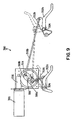
- Figs. 8 and 9 illustrate a lift and lower system 300 for raising and lowering the cutting units 30 of mower 2 or 102.
- Lift and lower system 300 accomplishes this task using only a single electric drive motor 301 and a novel linkage between motor 301 and cutting units 30. This linkage allows cutting units 30 to raise and lower in a timed sequence - some cutting units 30 will raise and/or lower before others.
- System 300 is simple and durable.
- a lift arm 302 rotatable about a horizontal axis 304 is normally provided for each cutting unit 30 as part of mower 2 or 102.
- Lift arm 302 engages beneath a portion of suspension 34 to lift upwardly on suspension 34, and hence on the cutting unit, when lift arm 302 rotates about horizontal axis 304.
- One such lift arm 302a for cutting unit 30a is shown in Fig. 1, but there is a similar lift arm 302 for each cutting unit.
- the same timing relationship is also true for lowering.
- the two front cutting units 30a and 30b desirably lower before center cutting unit 30c lowers.
- Lift and lower system 300 includes a single rotatable crankshaft 306 mounted by bearings 308 to some portion of mower 2 or 102.
- Crankshaft 306 includes a plurality of crankarms 309a, 309b and 309c which are connected to one end of connecting rods 310a, 310b and 310c, respectively.
- the other end of the connecting rods are connected to links 312a, 312b and 312c carried on lift arms 302 of cutting units 30a, 30b and 30c, respectively.
- the crankarm and connecting rod linkages to the two front cutting units 30a and 30b are identically connected to crankshaft 306 so that these two cutting units will lift and lower together.
- the crankarm and connecting rod linkage to the center cutting unit 30c is different so that the lifting and lowering of this cutting unit is timed to occur at different times than that of the front cutting units 30a and 30b.
- This means includes a drive wheel 314 mounted on crankshaft 306.
- Drive wheel 306 is engaged by a worm 316 that is rotated by a single electric drive motor 301.
- Drive motor 301 is designed to rotate worm 316 and drive wheel 314 to rotate crankshaft 306 in a first increment of rotation to raise cutting units 30, i.e. from 0 to 180°, and to then subsequently rotate crankshaft 306 in a second increment of rotation to lower cutting units 30, i.e. from 180 to 360°.
- FIG. 9 the operation of lift and lower system 300 is illustrated by the solid and phantom lines of the components.
- the components are shown in solid lines in the position they would have when cutting units 30 are lowered onto the ground.
- the components are shown in phantom lines in the position they would have when cutting units 30 have been raised from the ground for the purpose of transport or the like.
- crankshaft 306 is rotated counter-clockwise 180° by motor 301, worm 316 and drive wheel 314.
- the connecting rods 310a and 310b to the two front cutting units almost immediately begin to rise due to where they connect to their respective crankarms 309a and 309b and the orientation of these crankarms on crankshaft 306.
- the lift arms 302 for the two front cutting units begin to rotate counter-clockwise quite soon during the initial portion of this increment of rotation of crankshaft 306 to raise the two front cutting units.
- mower 2 has been illustrated as a riding mower herein, it is obvious that the principles thereof can be applied to walk behind mowers as well.
- cutting units 30 can have other forms than that shown herein, e.g. cutting units having rotary blades.
- the principles of this invention can be applied to turf maintenance vehicles other than mowers or to turf maintenance operating units other than cutting units.
- the lift and lower system 300 shown in Figs. 8 and 9 can be used to lift and lower other types of turf maintenance operating units carried on a vehicle, such as other turf cutters, sand trap rakes, or grooming, thatching or rolling implements. Accordingly, the scope of this invention is to be limited only by the appended claims.
Landscapes
- Life Sciences & Earth Sciences (AREA)
- Environmental Sciences (AREA)
- Harvester Elements (AREA)
Claims (13)
- Elektrisch betriebene Raseninstandhaltungsmaschine (2), umfassend:a) einen Rahmen (4);b) mehrere bodenkontaktierende Räder (6a-6d), befestigt am Rahmen (4) zum Tragen des Rahmens (4) für eine Bewegung über dem Boden;c) zumindest einen Elektromotor (18), der mit zumindest einem der bodenkontaktierenden Räder (6a-6d) zum Drehen zusammenwirkt, um eine Beförderung des Rahmens (4) zugewährleisten;d) zumindest eine Betriebseinheit (30a-30c), die vom Rahmen (4) getragen ist zur Ausführung der Raseninstandhaltung;e) zumindest einen Elektromotor (36), der mit der Betriebseinheit (30a-30c) zusammenwirkt, um die Betriebseinheit (30a-30c) anzutreiben; undf) ein elektrisches Antriebssystem (43), dass am Rahmen (4) befestigt ist, um die elektrischen Motoren (36) mit elektrischer Energie zu versorgen, wobei das elektrische Antriebssystem (43) umfasst:(i) einen internen Verbrennungsmotor (40);(ii) einen elektrischen Generator (42), mechanisch angetrieben durch den Motor (40) zur Erzeugung elektrischer Energie;(iii) eine Batterie (44) zur Speicherung der elektrischen Energie; und(iv) Mittel zur Verbindung des Elektromotors (36) mit dem elektrischen Generator (42) und mit der Batterie (44), um elektrische Energie zur Versorgung des Elektromotors (36) vom elektrischen Generator (42) und/oder der Batterie (44) zu nutzen.
- Rasensinstandhaltungsmaschine gemäß Anspruch 1,
dadurch gekennzeichnet, dass ein Schalter zum Abschalten des internen Verbrennungsmotors vorgesehen ist, wodurch der elektrische Generator abschaltet, so dass die Batterie die alleinige Quelle für elektrische Energie zur Versorgung des Elektromotors darstellt. - Raseninstandhaltungsmaschine gemäß Anspruch 2,
dadurch gekennzeichnet, dass der Schalter selektiv vom Bediener der Maschine betätigbar ist, damit der Bediener über die Betätigung entscheiden kann, um die Batterie als alleinige Quelle für elektrische Energie für den Elektromotor auszuwählen. - Raseninstandhaltungsmaschine nach Anspruch 2,
dadurch gekennzeichnet, dass Mittel zur Sensierung des Ladezustandes der Batterie vorgesehen sind, und dass Mittel zur Auswertung des Ladezustandes der Batterie für einen Bediener der Maschine vorhanden sind. - Raseninstandhaltungsmaschine nach Anspruch 4,
dadurch gekennzeichnet, dass eine Anzeige zum Signalisieren des Ladezustandes der Batterie bei Unterschreiten eines definierten Minimums für den Bediener der Maschine vorgesehen ist. - Raseninstandhaltungsmaschine nach Anspruch 5,
dadurch gekennzeichnet, dass Mittel zur Verhinderung eines ausschließlichen Betriebs über die Batterie vorgesehen sind, wenn der Ladezustand der Batterie unter dem definierten Minimum liegt. - Raseninstandhaltungsmaschine nach Anspruch 1,
dadurch gekennzeichnet, dass der elektrische Generator mit der Batterie in Verbindung steht, um die Batterie während des Betriebs des Verbrennungsmotors wieder aufzuladen. - Raseninstandhaltungsmaschine nach Anspruch 1,
dadurch gekennzeichnet, dass der elektrische Generator ein Wechselstromgenerator ist. - Raseninstandhaltungsmaschine nach Anspruch 8,
dadurch gekennzeichnet, dass eine Steuerung zum Steuern der Elektroenergie des Elektromotors vorgesehen ist, wobei die Steuerung weiterhin mit den Magnetfeldspulenwindungen des Wechselstromgenerators in Verbindung steht, um den Betrieb des Wechselstromgenerators zu steuern. - Raseninstandhaltungsmaschine nach Anspruch 1,
dadurch gekennzeichnet, dass zwei der am Rahmen befestigten Räder individuell durch separate Elektromotoren angetrieben sind, die mit dem elektrischen Antriebssystem in Verbindung stehen. - Raseninstandhaltungsmaschine nach Anspruch 10,
dadurch gekennzeichnet, dass ein Lenkrad vorgesehen ist, um die Maschine zu lenken, wobei ferner eine Steuerung zum Steuern der Elektroenergie vom elektrischen Antriebssystem zu den Elektromotoren vorgesehen ist, wobei die Steuerung Mittel zum Reagieren auf eine Lenkbewegung aufweist, um die zu den elektrischen Motoren zugeführte elektrische Energie entsprechend der Lenkbewegung zu beeinflussen. - Raseninstandhaltungsmaschine nach Anspruch 1.
dadurch gekennzeichnet, dass die Maschine nach Art einer Grasmähmaschine ausgebildet ist, wobei die Betriebseinheit eine Schneideeinheit darstellt. - Raseninstandhaltungsmaschine nach Anspruch 12,
dadurch gekennzeichnet, dass die Grasmähmaschine ein bemannter Rasenmäher ist.
Applications Claiming Priority (3)
| Application Number | Priority Date | Filing Date | Title |
|---|---|---|---|
| US1145096P | 1996-02-09 | 1996-02-09 | |
| US11450P | 1996-02-09 | ||
| PCT/US1997/001853 WO1997028681A2 (en) | 1996-02-09 | 1997-02-07 | Electric drive riding mower |
Publications (2)
| Publication Number | Publication Date |
|---|---|
| EP0959660A2 EP0959660A2 (de) | 1999-12-01 |
| EP0959660B1 true EP0959660B1 (de) | 2003-06-25 |
Family
ID=21750431
Family Applications (1)
| Application Number | Title | Priority Date | Filing Date |
|---|---|---|---|
| EP97905781A Expired - Lifetime EP0959660B1 (de) | 1996-02-09 | 1997-02-07 | Mäher mit elektromotorischem antrieb |
Country Status (5)
| Country | Link |
|---|---|
| US (2) | US7610975B1 (de) |
| EP (1) | EP0959660B1 (de) |
| CA (1) | CA2245772A1 (de) |
| DE (1) | DE69723109T2 (de) |
| WO (1) | WO1997028681A2 (de) |
Cited By (1)
| Publication number | Priority date | Publication date | Assignee | Title |
|---|---|---|---|---|
| US7735592B2 (en) | 2008-01-28 | 2010-06-15 | Textron Innovations Inc. | Regulated output voltage generator-set applied to mobile equipment in the turf industry |
Families Citing this family (90)
| Publication number | Priority date | Publication date | Assignee | Title |
|---|---|---|---|---|
| US6082084A (en) | 1995-11-13 | 2000-07-04 | Ransomes America Corporation | Electric riding mower with electric steering system |
| US6571542B1 (en) * | 1999-03-25 | 2003-06-03 | Textron Inc. | Electric drive mower with interchangeable power sources |
| US7533747B2 (en) | 2000-01-26 | 2009-05-19 | E-Traction Europe B.V. | Wheel provided with driving means |
| NL1014182C2 (nl) * | 2000-01-26 | 2001-07-27 | Special Products For Industry | Wiel voorzien van aandrijfmiddelen. |
| DE10027531A1 (de) * | 2000-06-02 | 2001-01-18 | Johannes Hanusch | Ferngesteuerte und progammierbare Bodenbearbeitungsmaschine (Rasenmäher) mit Hybrid-Allradantrieb |
| US6729117B2 (en) * | 2000-08-31 | 2004-05-04 | David S. Frazer | Spindle assembly for rotary mower |
| US7007446B2 (en) | 2000-10-26 | 2006-03-07 | Textron Inc. | Battery-powered walk-behind greensmower |
| US6523334B1 (en) | 2000-10-26 | 2003-02-25 | Textron Inc. | Battery-powered walk-behind greensmower |
| US6604348B2 (en) * | 2001-02-06 | 2003-08-12 | Deere & Company | Mower with engine-driven blade and electrical propulsion |
| US6487837B1 (en) * | 2001-06-05 | 2002-12-03 | Textron Inc. | Articularly mounted battery-powered walk-behind reel lawnmower |
| US7340877B2 (en) * | 2001-09-19 | 2008-03-11 | Crosstech Manufacturing, Inc. | Cutter unit support roller |
| EP1391370A1 (de) * | 2002-08-23 | 2004-02-25 | Rapid Technic AG | Selbstfahrende, lenkbare Arbeitsmaschine |
| JP2006507447A (ja) | 2002-11-22 | 2006-03-02 | 本田技研工業株式会社 | 発電システムを備える動力装置 |
| WO2004057166A2 (en) * | 2002-11-22 | 2004-07-08 | Honda Motor Company, Ltd. | Hybrid power equipment |
| US6904740B2 (en) | 2003-02-11 | 2005-06-14 | Textron Inc. | Articulating handle for a walk-behind mower |
| US7237374B2 (en) | 2003-09-26 | 2007-07-03 | Scag Power Equipment, Inc. | Roller assembly for striping a lawn |
| US7051498B2 (en) * | 2004-05-21 | 2006-05-30 | Textron Inc. | Traction enhancement system for turf mowers |
| US7240756B2 (en) | 2004-05-21 | 2007-07-10 | Textron Inc. | Method of operator presence control on walk behind powered equipment |
| JP2006238723A (ja) * | 2005-02-28 | 2006-09-14 | Mitsuwa:Kk | 枝豆収穫機 |
| US7677017B2 (en) | 2005-06-28 | 2010-03-16 | Textron Innovations Inc. | Modular power source for walk-behind mower |
| US7392869B2 (en) * | 2005-11-01 | 2008-07-01 | Textron Inc. | Modular power source for riding mower |
| DE602008001256D1 (de) | 2007-01-15 | 2010-07-01 | Kanzaki Kokyukoki Mfg Co Ltd | Rasenmäher |
| US7437864B2 (en) * | 2007-02-16 | 2008-10-21 | Deere & Company | Shift mechanism for trim mower cutting units |
| WO2009036211A2 (en) | 2007-09-11 | 2009-03-19 | Hydro-Gear Limited Partnership | Electric drive vehicle control system |
| US8207693B2 (en) * | 2007-09-11 | 2012-06-26 | Hydro-Gear Limited Partnership | Controller assemblies for electric drive utility vehicles |
| US8091332B2 (en) * | 2007-09-26 | 2012-01-10 | John Deere Enschede B.V. | Mower deck with air inlets |
| US7954308B2 (en) * | 2008-01-25 | 2011-06-07 | Deere & Company | Frequency of clip adjustment system and method for reel mower cutting unit |
| US8275502B2 (en) | 2008-01-28 | 2012-09-25 | Textron Innovations Inc. | Braking regeneration energy shunt system |
| US20090277149A1 (en) * | 2008-05-07 | 2009-11-12 | University Of Delaware | High lift mower for plastic mulch |
| FR2940881B1 (fr) * | 2009-01-09 | 2011-01-21 | Etesia | Tondeuse electrique a conducteur porte et a alimentation autonome en fonctionnement |
| US8099936B2 (en) * | 2009-01-27 | 2012-01-24 | Textron Innovations Inc. | Electrically powered flail mower |
| CN101861781B (zh) * | 2009-04-17 | 2013-04-03 | 苏州宝时得电动工具有限公司 | 自驱式割草机 |
| EP2448394B1 (de) | 2009-06-01 | 2021-01-06 | Husqvarna AB | Rasenmäher |
| US8191343B1 (en) | 2009-06-26 | 2012-06-05 | Hydro-Gear Limited Partnership | Systems and methods for cooling a controller assembly |
| JP2011079510A (ja) | 2009-09-10 | 2011-04-21 | Makita Corp | 電動車 |
| US8161720B1 (en) * | 2009-12-03 | 2012-04-24 | Humphrey John L | Grass treatment unit for walk behind greensmower |
| US20110179779A1 (en) * | 2010-01-28 | 2011-07-28 | Cummins Power Generation, Inc. | Emissions treatment in genset engines through air injection into the exhaust system of a genset |
| US8104252B1 (en) * | 2010-02-04 | 2012-01-31 | Godley Jr James E | Multi-functional tool heads for lawn mowers and associated method |
| GB201007566D0 (en) * | 2010-05-06 | 2010-06-23 | Agco Sa | Tractor with hybrid power system |
| EP2666347B1 (de) * | 2011-01-19 | 2018-10-10 | Yanmar Co., Ltd. | Aufsitzrasenmäher |
| WO2012132564A1 (ja) * | 2011-03-31 | 2012-10-04 | 株式会社マキタ | ハイブリッド駆動方式の携帯型作業機 |
| US9210839B2 (en) | 2011-07-14 | 2015-12-15 | Husqvarna Ab | Riding lawn mower including battery powered cutting system |
| US20140165524A1 (en) * | 2011-07-14 | 2014-06-19 | Husqvarna Ab | Riding Lawn Mower Including Battery Powered Drive System |
| WO2013009323A2 (en) | 2011-07-14 | 2013-01-17 | Husqvarna Ab | Battery powered lawn care vehicle with efficient drive controller |
| EP2731815A4 (de) | 2011-07-14 | 2015-10-07 | Husqvarna Ab | Fahrender rasenmäher mit verteiltem batteriesystem |
| EP2731413B1 (de) * | 2011-07-14 | 2017-10-04 | Husqvarna AB | Batteriebetriebenes rasenpflegefahrzeug mit motoreffizienzanzeige |
| US8490371B2 (en) | 2011-12-20 | 2013-07-23 | Cnh Canada, Ltd. | Modular electric disc cutterbar and controller |
| US8863485B2 (en) | 2012-01-05 | 2014-10-21 | Briggs & Stratton Corporation | Hybrid lawn mower drive system |
| DE102012100541A1 (de) * | 2012-01-23 | 2013-07-25 | As-Motor Germany Gmbh & Co. Kg | Fahrbare Vorrichtung zum Zerkleinern von Pflanzen |
| US20130207611A1 (en) * | 2012-02-09 | 2013-08-15 | Timothy P. Sosnowski | System and method of managing a lithium ion battery pack in a walk mower |
| JP2013252073A (ja) * | 2012-06-05 | 2013-12-19 | Kubota Corp | 対地作業ユニットを装備した作業車 |
| US9027317B2 (en) | 2012-08-31 | 2015-05-12 | Deere & Company | Reel mower grass catcher carrier |
| JP2014073566A (ja) * | 2012-10-05 | 2014-04-24 | Makita Corp | 動力工具 |
| CA2888220C (en) | 2012-10-17 | 2017-01-17 | Husqvarna Ab | Smart ignition system |
| US9637000B2 (en) | 2012-11-06 | 2017-05-02 | Agco Sa | Tractor with hybrid power system |
| US9241440B2 (en) | 2013-03-01 | 2016-01-26 | Cnh Industrial Canada Ltd. | Control system for a disc cutterbar using stubble cut quality feedback |
| US9113596B2 (en) * | 2013-03-15 | 2015-08-25 | The Toro Company | Hybrid electric turf mower with power shed and power boost |
| US9872438B2 (en) | 2013-03-15 | 2018-01-23 | Mtd Products Inc | Battery-electric and internal-combustion engine assist hybrid propulsion and implement drive work systems |
| WO2014203422A1 (ja) * | 2013-06-19 | 2014-12-24 | ヤンマー株式会社 | 電動作業車両 |
| JP6141161B2 (ja) * | 2013-09-25 | 2017-06-07 | 株式会社クボタ | 走行車両 |
| US9499199B1 (en) | 2014-04-23 | 2016-11-22 | Hydro-Gear Limited Partnership | Hybrid vehicle |
| US10368485B2 (en) * | 2014-06-13 | 2019-08-06 | Wright Manufacturing, Inc. | Lawn mower with improved cutting structure |
| WO2016057837A1 (en) * | 2014-10-10 | 2016-04-14 | Autonomous Tractor Corporation | Contour following mowing module |
| EP3217779B1 (de) * | 2014-11-14 | 2021-09-08 | Techtronic Industries Company Limited | Hybrider wechselstrom/gleichstrom-rasenmäher mit wechselstrom/gleichstrom-umschaltsystem |
| US9775288B2 (en) | 2015-02-27 | 2017-10-03 | Deere & Company | Rotary cutting deck with asymmetric rear discharge opening |
| US10148202B2 (en) | 2015-10-16 | 2018-12-04 | Kohler Co. | Hybrid device with segmented waveform converter |
| US10063097B2 (en) | 2015-10-16 | 2018-08-28 | Kohler Co. | Segmented waveform converter on controlled field variable speed generator |
| US10778123B2 (en) | 2015-10-16 | 2020-09-15 | Kohler Co. | Synchronous inverter |
| US10148207B2 (en) | 2015-10-16 | 2018-12-04 | Kohler Co. | Segmented waveform converter on controlled field variable speed generator |
| FR3054774B1 (fr) | 2016-08-02 | 2019-05-17 | Rousseau | Dispositif de fauchage de type epareuse comportant un equipement de coupe/broyage mis en action a l'aide d'un moteur electrique |
| US10820500B2 (en) * | 2017-04-11 | 2020-11-03 | Diamond Mowers, Llc | Mower deck dual wedge system |
| US11206759B2 (en) * | 2017-11-21 | 2021-12-28 | The Toro Company | Mower quick height of cut adjustment |
| US12342761B2 (en) | 2017-12-28 | 2025-07-01 | Nanjing Chervon Industry Co., Ltd. | Outdoor moving device |
| EP4570055A3 (de) | 2017-12-28 | 2025-08-27 | Nanjing Chervon Industry Co., Ltd. | Elektrischer rasenmäher |
| US11173780B2 (en) | 2018-01-04 | 2021-11-16 | Delta Systems, Inc. | Hybrid mower with electric blade control system |
| US10863669B2 (en) * | 2018-01-17 | 2020-12-15 | Victor Lartey | Lawn mowing assembly |
| US11071250B2 (en) * | 2018-02-08 | 2021-07-27 | Firefly Automatix, Inc. | Mower deck roller assembly |
| WO2019180851A1 (ja) * | 2018-03-20 | 2019-09-26 | 本田技研工業株式会社 | 作業機 |
| US11191209B2 (en) * | 2018-03-26 | 2021-12-07 | Deere & Company | Mower deck level adjuster |
| CN210610342U (zh) | 2018-09-27 | 2020-05-26 | 南京德朔实业有限公司 | 割草机 |
| CA3114468C (en) | 2018-09-27 | 2022-04-12 | Nanjing Chervon Industry Co., Ltd. | Lawn mower |
| GB2578586B (en) * | 2018-10-31 | 2021-12-22 | Allett Ltd | Mower with switch |
| US11785885B2 (en) * | 2019-01-31 | 2023-10-17 | The Toro Company | Mower with ganged reel cutting units having automatic clip control in both straight ahead motion and in turns |
| USD995569S1 (en) | 2019-04-18 | 2023-08-15 | Nanjing Chervon Industry Co., Ltd. | Mower blade assembly |
| US11122738B2 (en) * | 2019-04-23 | 2021-09-21 | Honda Motor Co., Ltd. | Cutter housing assembly for a lawnmower, lawnmower having same, and convertible lawnmower |
| US11427091B1 (en) | 2019-04-29 | 2022-08-30 | Parker-Hannifin Corporation | Electric drive system for a mower |
| CN218998877U (zh) * | 2021-06-25 | 2023-05-12 | 南京泉峰科技有限公司 | 骑乘式割草机 |
| SE546957C2 (en) * | 2021-12-21 | 2025-03-18 | Husqvarna Ab | Cutting Assembly and Lawnmower |
| EP4381927A1 (de) * | 2022-08-23 | 2024-06-12 | Black & Decker, Inc. | Steuermodul für hochleistungsmotor |
| US12527251B2 (en) | 2022-10-05 | 2026-01-20 | Deere & Company | Radial frequency of clip control system |
Family Cites Families (43)
| Publication number | Priority date | Publication date | Assignee | Title |
|---|---|---|---|---|
| US1790635A (en) * | 1931-01-27 | arendt | ||
| US2057417A (en) | 1931-07-18 | 1936-10-13 | Toro Mfg Company | Gang lawn mower |
| US2578880A (en) * | 1945-10-03 | 1951-12-18 | Rpm Mfg Company | Rotating cutting disk-type mower |
| US2731007A (en) * | 1953-01-22 | 1956-01-17 | Toro Mfg Corp Of Minnesota | Gasoline motor starting device |
| US3028717A (en) * | 1957-07-31 | 1962-04-10 | Scott & Sons Co O M | Power mower |
| US2972218A (en) | 1958-05-23 | 1961-02-21 | Toro Mfg Corp | Power mower with full floating cutting unit |
| US2968906A (en) | 1958-09-08 | 1961-01-24 | Toro Mfg Corp | Lawn mower roller and support |
| US3496707A (en) * | 1968-01-15 | 1970-02-24 | Philip B Kobey | Hinged rotary mower housing |
| JPS4930648B1 (de) * | 1969-12-12 | 1974-08-15 | ||
| AU1346370A (en) | 1970-04-06 | 1971-10-07 | Francis Ian' Showell | Accompanied by a provisional specification improved ganged mower |
| DE2049609A1 (de) * | 1970-10-09 | 1972-04-13 | Zündapp-Werke GmbH, 8000 München | Rasenmäher mit motorischem, insbesondere elektromotorischem Antrieb |
| US3680295A (en) * | 1971-08-20 | 1972-08-01 | Harry T Rutherford | Safety rotary mower |
| US3732671A (en) * | 1971-08-31 | 1973-05-15 | Deere & Co | Electric drive riding mower |
| US4196785A (en) * | 1977-02-16 | 1980-04-08 | Downing James H Jr | All-electric A.C. tractor |
| US4113045A (en) | 1977-02-16 | 1978-09-12 | Downing Jr James H | All-electric a.c. tractor |
| FR2387813A1 (fr) * | 1977-04-18 | 1978-11-17 | Lacombe Jacques | Dispositif de traction pour vehicules agricoles |
| NZ184157A (en) * | 1977-05-19 | 1979-11-01 | Whimp Rg | Gang mower with reels powered by individual electric motors or all powered by one electric motor |
| US4378668A (en) * | 1979-09-17 | 1983-04-05 | Brad Gullett | Lawnmower-edge trimmer |
| US4333302A (en) * | 1981-03-13 | 1982-06-08 | Ronald Thomas | Combined A.C./D.C. electric lawn mower |
| US4443997A (en) * | 1982-03-03 | 1984-04-24 | Bahram Namdari | Apparatus for vacuum collection and compacting of leaves and grass clippings |
| US4466235A (en) * | 1983-01-10 | 1984-08-21 | Cole Denver C | Rotary mower |
| US4968941A (en) * | 1988-07-13 | 1990-11-06 | Rogers Wesley A | Apparatus for monitoring the state of charge of a battery |
| US4870811A (en) * | 1988-11-28 | 1989-10-03 | Steele Robert M | Gasoline powered electrical lawn mower |
| US4964265A (en) | 1989-09-11 | 1990-10-23 | Young Carl W | Remotely controlled lawn mower |
| US4987729A (en) * | 1990-04-10 | 1991-01-29 | Paytas Anthony R | Solar powered mower |
| US5117616A (en) * | 1990-07-23 | 1992-06-02 | Mclane Frank E | Mulching lawn mower |
| US5133176A (en) | 1990-07-27 | 1992-07-28 | The Toro Company | Multi-bladed mulching mower |
| JPH04166475A (ja) | 1990-10-30 | 1992-06-12 | Kubota Corp | 乗用型芝刈機 |
| US5195311A (en) * | 1991-09-04 | 1993-03-23 | Holland Charles R | Collapsible discharge deflecting chute for rotary mowers |
| JP3044880B2 (ja) * | 1991-11-22 | 2000-05-22 | トヨタ自動車株式会社 | シリーズハイブリッド車の駆動制御装置 |
| JP3000804B2 (ja) * | 1992-10-21 | 2000-01-17 | 日産自動車株式会社 | ハイブリッド型電気自動車 |
| US5356238A (en) * | 1993-03-10 | 1994-10-18 | Cedarapids, Inc. | Paver with material supply and mat grade and slope quality control apparatus and method |
| US5406778A (en) * | 1994-02-03 | 1995-04-18 | Ransomes America Corporation | Electric drive riding greens mower |
| US5442901A (en) * | 1994-07-22 | 1995-08-22 | Ryobi North America | Self-propelled mower |
| CA2150663A1 (en) * | 1994-07-22 | 1996-01-23 | William Ishmael | Control system |
| US5465564A (en) * | 1994-12-12 | 1995-11-14 | Moridge Manufacturing, Inc. | Convertible mower deck |
| US5502957A (en) * | 1995-03-29 | 1996-04-02 | Robertson; Charles W. | Electric lawn mower with intelligent control |
| US5667029A (en) * | 1995-05-31 | 1997-09-16 | New York Institute Of Technology | Drive system for hybrid electric vehicle |
| US5794422A (en) * | 1995-11-13 | 1998-08-18 | Ransomes America Corporation | Electric drive mower with motor generator set |
| US5656919A (en) * | 1995-11-14 | 1997-08-12 | Cruising Equipment, Inc. | Accurate battery state-of-charge monitoring and indicating apparatus and method |
| US5845475A (en) * | 1995-11-16 | 1998-12-08 | Exmark Mfg. Co., Inc. | Lawn mower having flow control baffles and removable mulching baffles |
| US6047530A (en) | 1997-02-03 | 2000-04-11 | Textron, Inc. | Gang-type rotary lawn mower |
| US6032441A (en) * | 1997-11-13 | 2000-03-07 | The Toro Company | Triplex trim mower with laterally adjustable cutting units |
-
1997
- 1997-02-07 EP EP97905781A patent/EP0959660B1/de not_active Expired - Lifetime
- 1997-02-07 DE DE69723109T patent/DE69723109T2/de not_active Expired - Lifetime
- 1997-02-07 WO PCT/US1997/001853 patent/WO1997028681A2/en not_active Ceased
- 1997-02-07 CA CA002245772A patent/CA2245772A1/en not_active Abandoned
-
2000
- 2000-01-10 US US09/480,044 patent/US7610975B1/en not_active Expired - Fee Related
- 2000-01-21 US US09/489,180 patent/US6484481B1/en not_active Expired - Lifetime
Cited By (1)
| Publication number | Priority date | Publication date | Assignee | Title |
|---|---|---|---|---|
| US7735592B2 (en) | 2008-01-28 | 2010-06-15 | Textron Innovations Inc. | Regulated output voltage generator-set applied to mobile equipment in the turf industry |
Also Published As
| Publication number | Publication date |
|---|---|
| US7610975B1 (en) | 2009-11-03 |
| US6484481B1 (en) | 2002-11-26 |
| AU2259697A (en) | 1997-08-28 |
| EP0959660A2 (de) | 1999-12-01 |
| DE69723109D1 (de) | 2003-07-31 |
| WO1997028681A2 (en) | 1997-08-14 |
| WO1997028681A3 (en) | 1997-11-20 |
| AU705432B2 (en) | 1999-05-20 |
| CA2245772A1 (en) | 1997-08-14 |
| DE69723109T2 (de) | 2003-11-27 |
Similar Documents
| Publication | Publication Date | Title |
|---|---|---|
| EP0959660B1 (de) | Mäher mit elektromotorischem antrieb | |
| WO1997028681A9 (en) | Electric drive riding mower | |
| US5540037A (en) | Control system for electric drive riding mower | |
| US6109009A (en) | Constant speed control for electric greens mower | |
| EP1457104B9 (de) | Elektrisch-selbstfahrender Rasenmäher | |
| EP1541446B1 (de) | Nutzfahrzeug | |
| US6857253B2 (en) | Electric riding mower with motor generator set and noise abatement | |
| US8544570B2 (en) | Riding lawn mower | |
| US20240081177A1 (en) | Mower with ganged reel cutting units having automatic clip control in both straight ahead motion and in turns | |
| US20080289309A1 (en) | Mower with Hybrid Prime Mover Having Fuel Cell, Brushless Electric Motors for Driving Cutting Units, and Electric/Hydraulic Actuator for Lift and Lower System | |
| AU705432C (en) | Electric drive riding mower | |
| JP2023124355A (ja) | 乗用型芝刈り機 |
Legal Events
| Date | Code | Title | Description |
|---|---|---|---|
| PUAI | Public reference made under article 153(3) epc to a published international application that has entered the european phase |
Free format text: ORIGINAL CODE: 0009012 |
|
| 17P | Request for examination filed |
Effective date: 19980819 |
|
| AK | Designated contracting states |
Kind code of ref document: A2 Designated state(s): DE FR GB |
|
| GRAH | Despatch of communication of intention to grant a patent |
Free format text: ORIGINAL CODE: EPIDOS IGRA |
|
| GRAH | Despatch of communication of intention to grant a patent |
Free format text: ORIGINAL CODE: EPIDOS IGRA |
|
| GRAA | (expected) grant |
Free format text: ORIGINAL CODE: 0009210 |
|
| AK | Designated contracting states |
Designated state(s): DE FR GB |
|
| REG | Reference to a national code |
Ref country code: GB Ref legal event code: FG4D |
|
| REF | Corresponds to: |
Ref document number: 69723109 Country of ref document: DE Date of ref document: 20030731 Kind code of ref document: P |
|
| ET | Fr: translation filed | ||
| PLBE | No opposition filed within time limit |
Free format text: ORIGINAL CODE: 0009261 |
|
| STAA | Information on the status of an ep patent application or granted ep patent |
Free format text: STATUS: NO OPPOSITION FILED WITHIN TIME LIMIT |
|
| 26N | No opposition filed |
Effective date: 20040326 |
|
| PGFP | Annual fee paid to national office [announced via postgrant information from national office to epo] |
Ref country code: DE Payment date: 20140219 Year of fee payment: 18 |
|
| PGFP | Annual fee paid to national office [announced via postgrant information from national office to epo] |
Ref country code: FR Payment date: 20140219 Year of fee payment: 18 |
|
| REG | Reference to a national code |
Ref country code: DE Ref legal event code: R119 Ref document number: 69723109 Country of ref document: DE |
|
| REG | Reference to a national code |
Ref country code: FR Ref legal event code: ST Effective date: 20151030 |
|
| PG25 | Lapsed in a contracting state [announced via postgrant information from national office to epo] |
Ref country code: DE Free format text: LAPSE BECAUSE OF NON-PAYMENT OF DUE FEES Effective date: 20150901 |
|
| PG25 | Lapsed in a contracting state [announced via postgrant information from national office to epo] |
Ref country code: FR Free format text: LAPSE BECAUSE OF NON-PAYMENT OF DUE FEES Effective date: 20150302 |
|
| PGFP | Annual fee paid to national office [announced via postgrant information from national office to epo] |
Ref country code: GB Payment date: 20160217 Year of fee payment: 20 |
|
| REG | Reference to a national code |
Ref country code: GB Ref legal event code: PE20 Expiry date: 20170206 |
|
| PG25 | Lapsed in a contracting state [announced via postgrant information from national office to epo] |
Ref country code: GB Free format text: LAPSE BECAUSE OF EXPIRATION OF PROTECTION Effective date: 20170206 |