EP3085861A1 - Schliesszylinder - Google Patents
Schliesszylinder Download PDFInfo
- Publication number
- EP3085861A1 EP3085861A1 EP16161395.5A EP16161395A EP3085861A1 EP 3085861 A1 EP3085861 A1 EP 3085861A1 EP 16161395 A EP16161395 A EP 16161395A EP 3085861 A1 EP3085861 A1 EP 3085861A1
- Authority
- EP
- European Patent Office
- Prior art keywords
- key
- core
- cylinder
- output
- cylinder according
- Prior art date
- Legal status (The legal status is an assumption and is not a legal conclusion. Google has not performed a legal analysis and makes no representation as to the accuracy of the status listed.)
- Granted
Links
- 230000008878 coupling Effects 0.000 claims abstract description 11
- 238000010168 coupling process Methods 0.000 claims abstract description 11
- 238000005859 coupling reaction Methods 0.000 claims abstract description 11
- 230000004913 activation Effects 0.000 claims abstract description 3
- 238000013475 authorization Methods 0.000 claims description 3
- 238000011156 evaluation Methods 0.000 claims description 3
- 230000005672 electromagnetic field Effects 0.000 claims 1
- 230000002441 reversible effect Effects 0.000 claims 1
- 230000005540 biological transmission Effects 0.000 description 1
- 235000013339 cereals Nutrition 0.000 description 1
Images
Classifications
-
- E—FIXED CONSTRUCTIONS
- E05—LOCKS; KEYS; WINDOW OR DOOR FITTINGS; SAFES
- E05B—LOCKS; ACCESSORIES THEREFOR; HANDCUFFS
- E05B47/00—Operating or controlling locks or other fastening devices by electric or magnetic means
- E05B47/06—Controlling mechanically-operated bolts by electro-magnetically-operated detents
- E05B47/0611—Cylinder locks with electromagnetic control
- E05B47/0638—Cylinder locks with electromagnetic control by disconnecting the rotor
- E05B47/0646—Cylinder locks with electromagnetic control by disconnecting the rotor radially
- E05B47/0649—Cylinder locks with electromagnetic control by disconnecting the rotor radially with a rectilinearly moveable coupling element
-
- E—FIXED CONSTRUCTIONS
- E05—LOCKS; KEYS; WINDOW OR DOOR FITTINGS; SAFES
- E05B—LOCKS; ACCESSORIES THEREFOR; HANDCUFFS
- E05B11/00—Devices preventing keys from being removed from the lock ; Devices preventing falling or pushing out of keys
-
- E—FIXED CONSTRUCTIONS
- E05—LOCKS; KEYS; WINDOW OR DOOR FITTINGS; SAFES
- E05B—LOCKS; ACCESSORIES THEREFOR; HANDCUFFS
- E05B15/00—Other details of locks; Parts for engagement by bolts of fastening devices
- E05B15/0053—Other details of locks; Parts for engagement by bolts of fastening devices means providing a stable, i.e. indexed, position of lock parts
- E05B15/006—Spring-biased ball or roller entering a notch
-
- E—FIXED CONSTRUCTIONS
- E05—LOCKS; KEYS; WINDOW OR DOOR FITTINGS; SAFES
- E05B—LOCKS; ACCESSORIES THEREFOR; HANDCUFFS
- E05B17/00—Accessories in connection with locks
- E05B17/04—Devices for coupling the turning cylinder of a single or a double cylinder lock with the bolt operating member
- E05B17/047—Devices for coupling the turning cylinder of a single or a double cylinder lock with the bolt operating member with rotating output elements forming part of cylinder locks, e.g. locking cams of double cylinder locks
-
- E—FIXED CONSTRUCTIONS
- E05—LOCKS; KEYS; WINDOW OR DOOR FITTINGS; SAFES
- E05B—LOCKS; ACCESSORIES THEREFOR; HANDCUFFS
- E05B47/00—Operating or controlling locks or other fastening devices by electric or magnetic means
- E05B47/06—Controlling mechanically-operated bolts by electro-magnetically-operated detents
- E05B47/0611—Cylinder locks with electromagnetic control
- E05B47/0638—Cylinder locks with electromagnetic control by disconnecting the rotor
- E05B47/0646—Cylinder locks with electromagnetic control by disconnecting the rotor radially
-
- E—FIXED CONSTRUCTIONS
- E05—LOCKS; KEYS; WINDOW OR DOOR FITTINGS; SAFES
- E05B—LOCKS; ACCESSORIES THEREFOR; HANDCUFFS
- E05B15/00—Other details of locks; Parts for engagement by bolts of fastening devices
- E05B15/16—Use of special materials for parts of locks
- E05B15/1614—Use of special materials for parts of locks of hard materials, to prevent drilling
- E05B2015/1628—Free-rotating protecting covers or discs
Definitions
- the invention relates to a lock cylinder, with a cylinder core rotatably mounted in the lock cylinder housing, which has a keyway for inserting a flat key and which has a clutch which can be activated by the key, which produces the rotary connection of the cylinder core with an output.
- the object of the invention is to provide a lock cylinder having a simplified structure, a high protection against manipulation and also core pull protection.
- the mechanism on the end remote from the electric drive end of the spindle can be designed as a conical slide, with the help of ball elements can be brought radially into positive engagement with the output, the output of the Schloisbartring.
- the drive may be an electromagnet that moves the conical slider between its two end positions.
- the power source for the electronics and the drive is housed either in the cylinder housing or in the key.
- the power source in the cylinder housing it is arranged accessible from the housing front side (outside of the door).
- the core head on a detent, which serves as a key trigger security or key withdrawal positioning.
- the cam has a detent that locks it in the coupling position.
- an evaluation is arranged in the cylinder core, which checks the key code and activates the electric drive with appropriate access authorization.
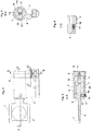
- FIG. 1 shows a side view of the lock cylinder housing 3 with a stuck key.
- the key has in the key cereal a battery 2 serving as a power supply as well as the electronic key coding.
- FIG. 2 shows a section through the lock cylinder housing 3 and introduced into the keyway of the cylinder core key 1.
- the cylinder core is divided into the core head 6, which has no connection to the actual cylinder core 7. The connection is made only by the key inserted in the keyway.
- the electronics 8 is brought to check the access authorization. Before the drive 9, a drill protection 20 can still be positioned.
- a drive 9 is non-rotatably arranged in the cylinder core 7 and - in the embodiment shown - provided with a threaded spindle 10 on which a conical slider 11 can be moved back and forth.
- the slider 11 has moved forward in driving position.
- the slider pushes two disposed in the cylinder core 7 balls 12 outwardly to the Schstedbartring 5.
- the Sch askedbartring has corresponding recesses 13 to allow torque transmission from the cylinder core or rather, the key on the Sch sautultring.
- a detent by means of ball 18 and lowering in the key shank 19 allows a simple key withdrawal protection, or key withdrawal position and also protection against false keys (lowering in the wrong position or in the wrong depth).
- the ball is pressed by the spring-loaded pin combination 16,17 in the direction of the closing channel and prevents the rotation of the core head 6.
- FIG. 4 shows the opposite recesses 15 in the cam 5 and the cam - latching position. After the closing operation of the lock pin 5 snaps when removing the key in a ball detent 14,15 and holds the cam in this position.
Landscapes
- Physics & Mathematics (AREA)
- Electromagnetism (AREA)
- Lock And Its Accessories (AREA)
Abstract
Description
- Die Erfindung betrifft einen Schließzylinder, mit einem im Schließzylindergehäuse drehbar gelagerten Zylinderkern, der einen Schlüsselkanal zum Einführen eines Flachschlüssels aufweist und der eine durch den Schlüssel aktivierbare Kupplung aufweist, die die Drehverbindung des Zylinderkerns mit einem Abtrieb herstellt.
- Es ist ein sehr großer Aufwand erforderlich, um die Kernposition bei rein elektronischen Zylindern gegen Verdrehen zu sichern (siehe DIN 1303: bis zu 30Nm), wenn man ein Design mit fester Kernposition wählt.
- Aufgabe der Erfindung ist es, einen Schließzylinder bereitzustellen, der einen vereinfachten Aufbau, einen hohen Manipulationsschutz und auch Kernziehschutz aufweist.
- Gelöst wird diese Aufgabe erfindungsgemäß mit einem Schließzylinder, mit einem im Schließzylindergehäuse drehbar gelagerten Zylinderkern, der einen Schlüsselkanal zum Einführen eines Flachschlüssels aufweist und der eine durch den Schlüssel aktivierbare Kupplung aufweist, die die Drehverbindung des Zylinderkerns mit einem Abtrieb herstellt, der dadurch gekennzeichnet ist,
- dass in der Stirnseite des Schließzylindergehäuses ein Kernkopf drehbar angeordnet ist,
- dass der Zylinderkern gegenüber dem Kernkopf frei drehbar hinter dem Kernkopf angeordnet ist,
- dass im Zylinderkern ein Elektroantrieb angeordnet ist, mit dessen Hilfe Kupplungselemente in einen Formschluss mit dem Abtrieb bringbar sind, um die Drehverbindung zwischen Zylinderkern und Abtrieb herzustellen,
- und dass die Aktivierung des Elektroantriebes durch den in den Schlüsselkanal eingeführten Schlüssel erfolgt,
- und dass der Schlüssel Kernkopf und Zylinderkern drehfest miteinander verbindet.
- Der Mechanismus am vom Elektroantrieb abgewandten Ende der Spindel kann als konischer Schieber ausgebildet sein, mit dessen Hilfe Kugelelemente radial in den Formschluss mit dem Abtrieb bringbar sind, wobei der Abtrieb der Schließbartring ist. In einer weiteren Ausführungsform kann der Antrieb ein Elektromagnet sein, der den konischen Schieber zwischen seinen beiden Endpositionen bewegt.
- Weiterhin ist eine Ausführung denkbar, bei der die Kugeln magnetisch sind und dadurch ständig am magnetischen Abtrieb (Schließbartring) anliegen. Jetzt kann der Schieber lastfrei um nur 90° gedreht werden, um die Kupplungsposition zu erreichen.
- Die Energiequelle für die Elektronik und den Antrieb ist wahlweise im Zylindergehäuse oder im Schlüssel untergebracht. Bei Anordnung der Energiequelle im Zylindergehäuse ist sie von der Gehäusestirnseite (Türaußenseite) her erreichbar angeordnet.
- Gemäß einer Weiterbildung der Erfindung weist der Kernkopf eine Rastung auf, die als Schlüsselabzugssicherung bzw. Schlüsselabzugspositionierung dient.
- Vorzugsweise weist auch der Schließbart eine Rastung auf, die ihn in der Kupplungsposition arretiert.
- Vorzugsweise ist im Zylinderkern eine Auswerteelektronik angeordnet ist, die den Schlüsselcode prüft und bei passender Zugangsberechtigung den Elektroantrieb aktiviert.
- Es gibt bisher kein Schließsystem, dass einen frei drehenden Zylinderkern hat; d.h. wo der Zylinderkern so lange frei drehend bleibt, bis mit einem berechtigten Schlüssel der Zylinderkern an den Schließbart gekuppelt wird. Dabei trägt der Schlüssel eine elektronische Codierung und die Spannungsversorgung für den im Kern befindlichen kuppelnden, elektromechanischen Mechanismus, sofern diese nicht im Zylindergehäuse untergebracht ist.
Hier kann noch angefügt werden, dass der Schlüssel trotzdem (obwohl der Kern frei drehend ist) nur horizontal oder vertikal in den Kern eingeführt werden kann (Abzugsposition). Dies kann mittels einer Kugelrastung einfach erreicht werden. Der Schließkanal kann zentrisch zum Kern sein, oder exzentrisch. - Die Erfindung soll nachfolgend mit Bezug auf ein in den Zeichnungen dargestelltes Ausführungsbeispiel näher erläutert werden.
-
-
Fig. 1 eine Seitenansicht eines Teils eines Schließzylindergehäuses mit eingestecktem Schlüssel, -
Fig. 2 den Schnitt A-A gemäßFigur 1 , -
Fig. 3 den Schnitt B-B gemäßFigur 1 und -
Fig. 4 den Schnitt C-C gemäßFigur 1 - Die
Figur 1 zeigt eine Seitenansicht des Schließzylindergehäuses 3 mit steckendem Schlüssel 1.
Der Schlüssel weist in der Schlüsselreide eine der Energieversorgung dienende Batterie 2 sowie die elektronische Schlüsselcodierung auf. -
Figur 2 zeigt einen Schnitt durch das Schließzylindergehäuse 3 und den in den Schlüsselkanal des Zylinderkerns eingeführten Schlüssel 1. Der Zylinderkern ist unterteilt in den Kernkopf 6, der keine Verbindung zum eigentlichen Zylinderkern 7 hat. Hergestellt wird die Verbindung erst durch den in den Schlüsselkanal eingeführten Schlüssel. Im Zylinderkern 7 ist die Elektronik 8 zur Prüfung der Zugangsberechtigung unter gebracht. Vor dem Antrieb 9 kann noch ein Bohrschutz 20 positioniert sein. - Ein Antrieb 9 ist drehfest im Zylinderkern 7 angeordnet und - bei dem gezeigten Ausführungsbeispiel - mit einer Gewindespindel 10 versehen, auf der ein konischer Schieber 11 vor und zurück bewegt werden kann. In der
Figur 2 ist der Schieber 11 nach vorne in Mitnahmeposition gefahren. Der Schieber drückt zwei in dem Zylinderkern 7 angeordnete Kugeln 12 nach außen an den Schließbartring 5. Der Schließbartring hat entsprechende Ausnehmungen 13, um eine Drehmomentübertragung vom Zylinderkern oder besser gesagt, vom Schlüssel auf den Schließbartring zu ermöglichen. - Eine Rastung mittels Kugel 18 und Senkung im Schlüsselschaft 19 ermöglicht eine einfache Schlüsselabzugssicherung, bzw. Schlüsselabzugsposition und auch Sicherung vor falschen Schlüsseln (Senkung an falscher Position oder in falscher Tiefe). Bei abgezogenem Schlüssel wird die Kugel durch die gefederte Stiftkombination 16,17 in Richtung Schließkanal gedrückt und die Verdrehung des Kernkopfes 6 verhindert.
-
Figur 4 zeigt die gegenüber liegenden Ausnehmungen 15 im Schließbart 5 und die Schließbart - Rastposition. Nach dem Schließvorgang rastet der Schließbart 5 beim Abziehen des Schlüssels in eine Kugelrastung 14,15 und hält den Schließbart in dieser Position.
Claims (10)
- Schließzylinder, mit einem im Schließzylindergehäuse (3) drehbar gelagerten Zylinderkern (7), der einen Schlüsselkanal zum Einführen eines Flachschlüssels (1) aufweist und der eine durch den Schlüssel aktivierbare Kupplung aufweist, die die Drehverbindung des Zylinderkerns mit einem Abtrieb herstellt,
dadurch gekennzeichnet,- dass in der Stirnseite des Schließzylindergehäuses ein Kernkopf (6) drehbar angeordnet ist,- dass der Zylinderkern (7) gegenüber dem Kernkopf (6) frei drehbar hinter dem Kernkopf angeordnet ist,- dass im Zylinderkern (7) ein Elektroantrieb (9) angeordnet ist, mit dessen Hilfe Kupplungselemente (11,12) in einen Formschluss mit dem Abtrieb (5) bringbar sind, um die Drehverbindung zwischen Zylinderkern (7) und Abtrieb (5) herzustellen,- und dass die Aktivierung des Elektroantriebs (9) durch den in den Schlüsselkanal eingeführten Schlüssel (1) erfolgt,- und dass der Schlüssel Kernkopf (6) und Zylinderkern (7) drehfest miteinander verbindet. - Schließzylinder nach Anspruch 1,
dadurch gekennzeichnet,
dass das Kupplungselement am vom Elektroantrieb abgewandten Ende einer Spindel (10) als konischer Schieber (11) ausgebildet ist, mit dessen Hilfe Kugelelemente (12) radial in den Formschluss mit dem Abtrieb (5) bringbar sind. - Schließzylinder nach einem der vorstehenden Ansprüche,
dadurch gekennzeichnet,
dass der Abtrieb (5) der Schließbartring ist. - Schließzylinder nach Anspruch 1 bis 3,
dadurch gekennzeichnet,
dass der Kernkopf (6) eine Rastung (16-19) aufweist, die als Schlüsselabzugssicherung bzw. Schlüsselabzugspositionierung dient. - Schließzylinder nach einem der vorstehenden Ansprüche,
dadurch gekennzeichnet,
dass der Abtrieb (5) eine Rastung (14,15) aufweist, die ihn in der Schlüsselabzugsposition arretiert. - Schließzylinder nach einem der vorstehenden Ansprüche,
dadurch gekennzeichnet,
dass im Zylinderkern (7) eine Auswerteelektronik (8) angeordnet ist, die den Schlüsselcode prüft und bei passender Zugangsberechtigung den Elektroantrieb (9) aktiviert. - Schließzylinder nach einem der vorstehenden Ansprüche,
dadurch gekennzeichnet,
dass der Schlüssel kontaktlos mit der im Zylinderkern (7) befindlichen Auswerteelektronik (8) kommuniziert und auch die benötigte Energie kontaktlos mittels elektromagnetischen Feldern überträgt. - Schließzylinder nach einem der vorstehenden Ansprüche,
dadurch gekennzeichnet,
dass der Flachschlüssel auch als Wendeschlüssel einsetzbar ist. - Schließzylinder nach einem der vorstehenden Ansprüche,
dadurch gekennzeichnet,
dass die Energiequelle im Zylindergehäuse oder im Schlüssel angeordnet ist. - Schließzylinder nach einem der vorstehenden Ansprüche,
dadurch gekennzeichnet,
dass die Kupplungselemente magnetische Kugeln sind, die an dem magnetischen Schließbartring ständig haften und der unmagnetische Schieber durch den Antrieb in der hinteren Position um 90° gedreht wird, um die formschlüssige Kupplung mit dem Abtrieb (Schließbartring) herzustellen.
Priority Applications (2)
| Application Number | Priority Date | Filing Date | Title |
|---|---|---|---|
| SI201630108T SI3085861T1 (sl) | 2015-04-09 | 2016-03-21 | Zaklepni cilinder |
| PL16161395T PL3085861T3 (pl) | 2015-04-09 | 2016-03-21 | Wkładka bębenkowa |
Applications Claiming Priority (1)
| Application Number | Priority Date | Filing Date | Title |
|---|---|---|---|
| DE102015105412.4A DE102015105412B3 (de) | 2015-04-09 | 2015-04-09 | Schließzylinder |
Publications (2)
| Publication Number | Publication Date |
|---|---|
| EP3085861A1 true EP3085861A1 (de) | 2016-10-26 |
| EP3085861B1 EP3085861B1 (de) | 2018-10-03 |
Family
ID=55587189
Family Applications (1)
| Application Number | Title | Priority Date | Filing Date |
|---|---|---|---|
| EP16161395.5A Active EP3085861B1 (de) | 2015-04-09 | 2016-03-21 | Schliesszylinder |
Country Status (6)
| Country | Link |
|---|---|
| EP (1) | EP3085861B1 (de) |
| DE (1) | DE102015105412B3 (de) |
| DK (1) | DK3085861T3 (de) |
| ES (1) | ES2704284T3 (de) |
| PL (1) | PL3085861T3 (de) |
| SI (1) | SI3085861T1 (de) |
Families Citing this family (1)
| Publication number | Priority date | Publication date | Assignee | Title |
|---|---|---|---|---|
| SE544858C2 (en) * | 2020-12-22 | 2022-12-13 | Zyax Ab | Locking device with a plunger, a driver and a transmission construction with a central ball and two outer balls and cavities |
Citations (7)
| Publication number | Priority date | Publication date | Assignee | Title |
|---|---|---|---|---|
| DE10065155A1 (de) * | 2000-12-23 | 2002-06-27 | Schulte Zylinderschl Gmbh | Kupplungsanordnung in einem Schließzylinder |
| WO2005001224A1 (de) * | 2003-06-23 | 2005-01-06 | Buga Technologies Gmbh | Elektromechanischer schliesszylinder |
| US20060156771A1 (en) * | 2002-12-23 | 2006-07-20 | Peter Hauri | Locking device |
| EP1717761A2 (de) * | 2005-04-25 | 2006-11-02 | CEStronics GmbH | Schließzylinder für einen ein elektronisches Schließgeheimnis tragenden Schlüssel |
| WO2012004734A1 (en) * | 2010-07-07 | 2012-01-12 | Giussani Techniques S.P.A. | Electronic lock, preferably of the reprogrammable type |
| EP2535487A1 (de) * | 2011-06-14 | 2012-12-19 | OMEC Serrature S.P.A. | Schliesszylinder |
| DE102013104366A1 (de) * | 2013-04-29 | 2014-10-30 | Uhlmann & Zacher Gmbh | Kupplung für ein elektromechanisches Schloss |
-
2015
- 2015-04-09 DE DE102015105412.4A patent/DE102015105412B3/de not_active Expired - Fee Related
-
2016
- 2016-03-21 PL PL16161395T patent/PL3085861T3/pl unknown
- 2016-03-21 EP EP16161395.5A patent/EP3085861B1/de active Active
- 2016-03-21 ES ES16161395T patent/ES2704284T3/es active Active
- 2016-03-21 DK DK16161395.5T patent/DK3085861T3/en active
- 2016-03-21 SI SI201630108T patent/SI3085861T1/sl unknown
Patent Citations (7)
| Publication number | Priority date | Publication date | Assignee | Title |
|---|---|---|---|---|
| DE10065155A1 (de) * | 2000-12-23 | 2002-06-27 | Schulte Zylinderschl Gmbh | Kupplungsanordnung in einem Schließzylinder |
| US20060156771A1 (en) * | 2002-12-23 | 2006-07-20 | Peter Hauri | Locking device |
| WO2005001224A1 (de) * | 2003-06-23 | 2005-01-06 | Buga Technologies Gmbh | Elektromechanischer schliesszylinder |
| EP1717761A2 (de) * | 2005-04-25 | 2006-11-02 | CEStronics GmbH | Schließzylinder für einen ein elektronisches Schließgeheimnis tragenden Schlüssel |
| WO2012004734A1 (en) * | 2010-07-07 | 2012-01-12 | Giussani Techniques S.P.A. | Electronic lock, preferably of the reprogrammable type |
| EP2535487A1 (de) * | 2011-06-14 | 2012-12-19 | OMEC Serrature S.P.A. | Schliesszylinder |
| DE102013104366A1 (de) * | 2013-04-29 | 2014-10-30 | Uhlmann & Zacher Gmbh | Kupplung für ein elektromechanisches Schloss |
Also Published As
| Publication number | Publication date |
|---|---|
| DE102015105412B3 (de) | 2016-07-07 |
| DK3085861T3 (en) | 2018-12-10 |
| ES2704284T3 (es) | 2019-03-15 |
| EP3085861B1 (de) | 2018-10-03 |
| SI3085861T1 (sl) | 2018-12-31 |
| PL3085861T3 (pl) | 2019-03-29 |
Similar Documents
| Publication | Publication Date | Title |
|---|---|---|
| DE3632904C2 (de) | ||
| EP2473690B1 (de) | Schliesseinrichtung | |
| EP2436858A2 (de) | Schließzylinder für ein Schloss | |
| EP2287423B1 (de) | Knaufzylinder | |
| EP0668422A1 (de) | Sperrmechanismus für ein Schloss | |
| EP1443162A2 (de) | Schliesszylinder und Schliessanordnung | |
| DE102007011554B4 (de) | Koppeleinheit für elektronische Schließ-Systeme | |
| EP3085861B1 (de) | Schliesszylinder | |
| EP2870310A2 (de) | Schliesszylinder-schlüssel-system | |
| DE202008007068U1 (de) | Vorrichtung zur Notentriegelung von elektronisch betätigten Schliesszylindern | |
| DE8104059U1 (de) | Zylinderschloss | |
| EP2931995B1 (de) | Schliesszylinder und wende-schlüssel mit schlüsselabzugssperre | |
| DE102004009992A1 (de) | Handhabe für ein Türschloss und Schloss mit derartiger Handhabe | |
| DE2902578C2 (de) | Mittels Permanentmagnetschlüssel betätigbarer Schließzylinder | |
| DE102005041974B3 (de) | Schliesszylinder mit Kupplung | |
| EP1164238A1 (de) | Schliesszylinder | |
| DE102013103051A1 (de) | Kupplungsvorrichtung | |
| DE102022119106B3 (de) | Schließzylinder mit gegen Drehung sperrbarem Zylinderkern | |
| CH334964A (de) | Einbaudoppelzylinder für Einsteckschlösser mit Schlüssel- und Handgriffbetätigung | |
| EP1338733B1 (de) | Schliesszylinder | |
| EP2952656B1 (de) | Profilzylinder mit einem zylindergehäuse | |
| WO2014000721A1 (de) | Schliessvorrichtung mit elektroaktivem polymer | |
| DE1728621C3 (de) | Drehzylinderschloß mit permanentmagnetischen, federlosen Zuhaltungsstiften | |
| DE102004030051B3 (de) | Schließvorrichtung | |
| DE202014104448U1 (de) | Schloss |
Legal Events
| Date | Code | Title | Description |
|---|---|---|---|
| PUAI | Public reference made under article 153(3) epc to a published international application that has entered the european phase |
Free format text: ORIGINAL CODE: 0009012 |
|
| AK | Designated contracting states |
Kind code of ref document: A1 Designated state(s): AL AT BE BG CH CY CZ DE DK EE ES FI FR GB GR HR HU IE IS IT LI LT LU LV MC MK MT NL NO PL PT RO RS SE SI SK SM TR |
|
| AX | Request for extension of the european patent |
Extension state: BA ME |
|
| 17P | Request for examination filed |
Effective date: 20170426 |
|
| RBV | Designated contracting states (corrected) |
Designated state(s): AL AT BE BG CH CY CZ DE DK EE ES FI FR GB GR HR HU IE IS IT LI LT LU LV MC MK MT NL NO PL PT RO RS SE SI SK SM TR |
|
| STAA | Information on the status of an ep patent application or granted ep patent |
Free format text: STATUS: REQUEST FOR EXAMINATION WAS MADE |
|
| GRAP | Despatch of communication of intention to grant a patent |
Free format text: ORIGINAL CODE: EPIDOSNIGR1 |
|
| STAA | Information on the status of an ep patent application or granted ep patent |
Free format text: STATUS: GRANT OF PATENT IS INTENDED |
|
| INTG | Intention to grant announced |
Effective date: 20180509 |
|
| GRAS | Grant fee paid |
Free format text: ORIGINAL CODE: EPIDOSNIGR3 |
|
| GRAA | (expected) grant |
Free format text: ORIGINAL CODE: 0009210 |
|
| STAA | Information on the status of an ep patent application or granted ep patent |
Free format text: STATUS: THE PATENT HAS BEEN GRANTED |
|
| AK | Designated contracting states |
Kind code of ref document: B1 Designated state(s): AL AT BE BG CH CY CZ DE DK EE ES FI FR GB GR HR HU IE IS IT LI LT LU LV MC MK MT NL NO PL PT RO RS SE SI SK SM TR |
|
| REG | Reference to a national code |
Ref country code: GB Ref legal event code: FG4D Free format text: NOT ENGLISH |
|
| REG | Reference to a national code |
Ref country code: CH Ref legal event code: EP Ref country code: AT Ref legal event code: REF Ref document number: 1048768 Country of ref document: AT Kind code of ref document: T Effective date: 20181015 |
|
| REG | Reference to a national code |
Ref country code: IE Ref legal event code: FG4D Free format text: LANGUAGE OF EP DOCUMENT: GERMAN Ref country code: DE Ref legal event code: R096 Ref document number: 502016002133 Country of ref document: DE |
|
| REG | Reference to a national code |
Ref country code: DK Ref legal event code: T3 Effective date: 20181203 |
|
| REG | Reference to a national code |
Ref country code: SE Ref legal event code: TRGR |
|
| REG | Reference to a national code |
Ref country code: NL Ref legal event code: FP |
|
| REG | Reference to a national code |
Ref country code: NO Ref legal event code: T2 Effective date: 20181003 |
|
| REG | Reference to a national code |
Ref country code: LT Ref legal event code: MG4D |
|
| REG | Reference to a national code |
Ref country code: GR Ref legal event code: EP Ref document number: 20180402888 Country of ref document: GR Effective date: 20190225 |
|
| REG | Reference to a national code |
Ref country code: ES Ref legal event code: FG2A Ref document number: 2704284 Country of ref document: ES Kind code of ref document: T3 Effective date: 20190315 |
|
| PG25 | Lapsed in a contracting state [announced via postgrant information from national office to epo] |
Ref country code: LT Free format text: LAPSE BECAUSE OF FAILURE TO SUBMIT A TRANSLATION OF THE DESCRIPTION OR TO PAY THE FEE WITHIN THE PRESCRIBED TIME-LIMIT Effective date: 20181003 Ref country code: LV Free format text: LAPSE BECAUSE OF FAILURE TO SUBMIT A TRANSLATION OF THE DESCRIPTION OR TO PAY THE FEE WITHIN THE PRESCRIBED TIME-LIMIT Effective date: 20181003 Ref country code: BG Free format text: LAPSE BECAUSE OF FAILURE TO SUBMIT A TRANSLATION OF THE DESCRIPTION OR TO PAY THE FEE WITHIN THE PRESCRIBED TIME-LIMIT Effective date: 20190103 Ref country code: HR Free format text: LAPSE BECAUSE OF FAILURE TO SUBMIT A TRANSLATION OF THE DESCRIPTION OR TO PAY THE FEE WITHIN THE PRESCRIBED TIME-LIMIT Effective date: 20181003 Ref country code: IS Free format text: LAPSE BECAUSE OF FAILURE TO SUBMIT A TRANSLATION OF THE DESCRIPTION OR TO PAY THE FEE WITHIN THE PRESCRIBED TIME-LIMIT Effective date: 20190203 |
|
| PG25 | Lapsed in a contracting state [announced via postgrant information from national office to epo] |
Ref country code: RS Free format text: LAPSE BECAUSE OF FAILURE TO SUBMIT A TRANSLATION OF THE DESCRIPTION OR TO PAY THE FEE WITHIN THE PRESCRIBED TIME-LIMIT Effective date: 20181003 Ref country code: PT Free format text: LAPSE BECAUSE OF FAILURE TO SUBMIT A TRANSLATION OF THE DESCRIPTION OR TO PAY THE FEE WITHIN THE PRESCRIBED TIME-LIMIT Effective date: 20190203 Ref country code: AL Free format text: LAPSE BECAUSE OF FAILURE TO SUBMIT A TRANSLATION OF THE DESCRIPTION OR TO PAY THE FEE WITHIN THE PRESCRIBED TIME-LIMIT Effective date: 20181003 |
|
| REG | Reference to a national code |
Ref country code: DE Ref legal event code: R097 Ref document number: 502016002133 Country of ref document: DE |
|
| PLBE | No opposition filed within time limit |
Free format text: ORIGINAL CODE: 0009261 |
|
| STAA | Information on the status of an ep patent application or granted ep patent |
Free format text: STATUS: NO OPPOSITION FILED WITHIN TIME LIMIT |
|
| PG25 | Lapsed in a contracting state [announced via postgrant information from national office to epo] |
Ref country code: SK Free format text: LAPSE BECAUSE OF FAILURE TO SUBMIT A TRANSLATION OF THE DESCRIPTION OR TO PAY THE FEE WITHIN THE PRESCRIBED TIME-LIMIT Effective date: 20181003 Ref country code: SM Free format text: LAPSE BECAUSE OF FAILURE TO SUBMIT A TRANSLATION OF THE DESCRIPTION OR TO PAY THE FEE WITHIN THE PRESCRIBED TIME-LIMIT Effective date: 20181003 Ref country code: RO Free format text: LAPSE BECAUSE OF FAILURE TO SUBMIT A TRANSLATION OF THE DESCRIPTION OR TO PAY THE FEE WITHIN THE PRESCRIBED TIME-LIMIT Effective date: 20181003 Ref country code: EE Free format text: LAPSE BECAUSE OF FAILURE TO SUBMIT A TRANSLATION OF THE DESCRIPTION OR TO PAY THE FEE WITHIN THE PRESCRIBED TIME-LIMIT Effective date: 20181003 |
|
| 26N | No opposition filed |
Effective date: 20190704 |
|
| PG25 | Lapsed in a contracting state [announced via postgrant information from national office to epo] |
Ref country code: MC Free format text: LAPSE BECAUSE OF FAILURE TO SUBMIT A TRANSLATION OF THE DESCRIPTION OR TO PAY THE FEE WITHIN THE PRESCRIBED TIME-LIMIT Effective date: 20181003 |
|
| PG25 | Lapsed in a contracting state [announced via postgrant information from national office to epo] |
Ref country code: IE Free format text: LAPSE BECAUSE OF NON-PAYMENT OF DUE FEES Effective date: 20190321 |
|
| PG25 | Lapsed in a contracting state [announced via postgrant information from national office to epo] |
Ref country code: MT Free format text: LAPSE BECAUSE OF FAILURE TO SUBMIT A TRANSLATION OF THE DESCRIPTION OR TO PAY THE FEE WITHIN THE PRESCRIBED TIME-LIMIT Effective date: 20181003 |
|
| PGFP | Annual fee paid to national office [announced via postgrant information from national office to epo] |
Ref country code: FR Payment date: 20210225 Year of fee payment: 6 Ref country code: GR Payment date: 20210211 Year of fee payment: 6 Ref country code: IT Payment date: 20210211 Year of fee payment: 6 Ref country code: CZ Payment date: 20210225 Year of fee payment: 6 Ref country code: FI Payment date: 20210309 Year of fee payment: 6 Ref country code: NL Payment date: 20210312 Year of fee payment: 6 Ref country code: LU Payment date: 20210310 Year of fee payment: 6 Ref country code: NO Payment date: 20210309 Year of fee payment: 6 |
|
| PG25 | Lapsed in a contracting state [announced via postgrant information from national office to epo] |
Ref country code: CY Free format text: LAPSE BECAUSE OF FAILURE TO SUBMIT A TRANSLATION OF THE DESCRIPTION OR TO PAY THE FEE WITHIN THE PRESCRIBED TIME-LIMIT Effective date: 20181003 |
|
| PGFP | Annual fee paid to national office [announced via postgrant information from national office to epo] |
Ref country code: GB Payment date: 20210310 Year of fee payment: 6 Ref country code: DK Payment date: 20210310 Year of fee payment: 6 Ref country code: BE Payment date: 20210217 Year of fee payment: 6 Ref country code: SI Payment date: 20210218 Year of fee payment: 6 Ref country code: SE Payment date: 20210311 Year of fee payment: 6 Ref country code: PL Payment date: 20210212 Year of fee payment: 6 Ref country code: TR Payment date: 20210318 Year of fee payment: 6 |
|
| PG25 | Lapsed in a contracting state [announced via postgrant information from national office to epo] |
Ref country code: HU Free format text: LAPSE BECAUSE OF FAILURE TO SUBMIT A TRANSLATION OF THE DESCRIPTION OR TO PAY THE FEE WITHIN THE PRESCRIBED TIME-LIMIT; INVALID AB INITIO Effective date: 20160321 |
|
| PGFP | Annual fee paid to national office [announced via postgrant information from national office to epo] |
Ref country code: ES Payment date: 20210402 Year of fee payment: 6 |
|
| PG25 | Lapsed in a contracting state [announced via postgrant information from national office to epo] |
Ref country code: MK Free format text: LAPSE BECAUSE OF FAILURE TO SUBMIT A TRANSLATION OF THE DESCRIPTION OR TO PAY THE FEE WITHIN THE PRESCRIBED TIME-LIMIT Effective date: 20181003 |
|
| REG | Reference to a national code |
Ref country code: FI Ref legal event code: MAE |
|
| REG | Reference to a national code |
Ref country code: NO Ref legal event code: MMEP Ref country code: DK Ref legal event code: EBP Effective date: 20220331 |
|
| PG25 | Lapsed in a contracting state [announced via postgrant information from national office to epo] |
Ref country code: FI Free format text: LAPSE BECAUSE OF NON-PAYMENT OF DUE FEES Effective date: 20220321 Ref country code: CZ Free format text: LAPSE BECAUSE OF NON-PAYMENT OF DUE FEES Effective date: 20220321 |
|
| REG | Reference to a national code |
Ref country code: NL Ref legal event code: MM Effective date: 20220401 |
|
| GBPC | Gb: european patent ceased through non-payment of renewal fee |
Effective date: 20220321 |
|
| REG | Reference to a national code |
Ref country code: BE Ref legal event code: MM Effective date: 20220331 |
|
| REG | Reference to a national code |
Ref country code: SI Ref legal event code: KO00 Effective date: 20221122 |
|
| PG25 | Lapsed in a contracting state [announced via postgrant information from national office to epo] |
Ref country code: SE Free format text: LAPSE BECAUSE OF NON-PAYMENT OF DUE FEES Effective date: 20220322 Ref country code: NO Free format text: LAPSE BECAUSE OF NON-PAYMENT OF DUE FEES Effective date: 20220331 Ref country code: NL Free format text: LAPSE BECAUSE OF NON-PAYMENT OF DUE FEES Effective date: 20220401 Ref country code: LU Free format text: LAPSE BECAUSE OF NON-PAYMENT OF DUE FEES Effective date: 20220321 Ref country code: GB Free format text: LAPSE BECAUSE OF NON-PAYMENT OF DUE FEES Effective date: 20220321 Ref country code: FR Free format text: LAPSE BECAUSE OF NON-PAYMENT OF DUE FEES Effective date: 20220331 |
|
| PG25 | Lapsed in a contracting state [announced via postgrant information from national office to epo] |
Ref country code: SI Free format text: LAPSE BECAUSE OF NON-PAYMENT OF DUE FEES Effective date: 20220322 Ref country code: GR Free format text: LAPSE BECAUSE OF NON-PAYMENT OF DUE FEES Effective date: 20221006 Ref country code: BE Free format text: LAPSE BECAUSE OF NON-PAYMENT OF DUE FEES Effective date: 20220331 |
|
| PG25 | Lapsed in a contracting state [announced via postgrant information from national office to epo] |
Ref country code: DK Free format text: LAPSE BECAUSE OF NON-PAYMENT OF DUE FEES Effective date: 20220331 |
|
| REG | Reference to a national code |
Ref country code: ES Ref legal event code: FD2A Effective date: 20230428 |
|
| PG25 | Lapsed in a contracting state [announced via postgrant information from national office to epo] |
Ref country code: IT Free format text: LAPSE BECAUSE OF NON-PAYMENT OF DUE FEES Effective date: 20220321 |
|
| PG25 | Lapsed in a contracting state [announced via postgrant information from national office to epo] |
Ref country code: ES Free format text: LAPSE BECAUSE OF NON-PAYMENT OF DUE FEES Effective date: 20220322 |
|
| PGFP | Annual fee paid to national office [announced via postgrant information from national office to epo] |
Ref country code: CH Payment date: 20230401 Year of fee payment: 8 |
|
| PG25 | Lapsed in a contracting state [announced via postgrant information from national office to epo] |
Ref country code: PL Free format text: LAPSE BECAUSE OF NON-PAYMENT OF DUE FEES Effective date: 20220321 |
|
| PGFP | Annual fee paid to national office [announced via postgrant information from national office to epo] |
Ref country code: AT Payment date: 20240226 Year of fee payment: 9 |
|
| PGFP | Annual fee paid to national office [announced via postgrant information from national office to epo] |
Ref country code: DE Payment date: 20240213 Year of fee payment: 9 |