EP3084332B1 - Reservoir a chauffer une liquide avec tuyauterie d'échange de chaleur et procédé de fabrication de la meme - Google Patents
Reservoir a chauffer une liquide avec tuyauterie d'échange de chaleur et procédé de fabrication de la meme Download PDFInfo
- Publication number
- EP3084332B1 EP3084332B1 EP14873070.8A EP14873070A EP3084332B1 EP 3084332 B1 EP3084332 B1 EP 3084332B1 EP 14873070 A EP14873070 A EP 14873070A EP 3084332 B1 EP3084332 B1 EP 3084332B1
- Authority
- EP
- European Patent Office
- Prior art keywords
- tubing
- end portion
- fluid
- outer tube
- inner tube
- Prior art date
- Legal status (The legal status is an assumption and is not a legal conclusion. Google has not performed a legal analysis and makes no representation as to the accuracy of the status listed.)
- Active
Links
- 239000007788 liquid Substances 0.000 title claims description 15
- 238000010438 heat treatment Methods 0.000 title claims description 14
- 238000004519 manufacturing process Methods 0.000 title claims description 3
- 238000000034 method Methods 0.000 title claims 4
- 239000012530 fluid Substances 0.000 claims description 43
- 238000004891 communication Methods 0.000 claims description 4
- 230000003014 reinforcing effect Effects 0.000 claims 1
- XLYOFNOQVPJJNP-UHFFFAOYSA-N water Substances O XLYOFNOQVPJJNP-UHFFFAOYSA-N 0.000 description 14
- 238000007789 sealing Methods 0.000 description 5
- 238000012360 testing method Methods 0.000 description 3
- 239000000853 adhesive Substances 0.000 description 1
- 230000001070 adhesive effect Effects 0.000 description 1
- 230000000052 comparative effect Effects 0.000 description 1
- 238000001514 detection method Methods 0.000 description 1
- 230000000694 effects Effects 0.000 description 1
- 238000004880 explosion Methods 0.000 description 1
- 230000005484 gravity Effects 0.000 description 1
- 238000007689 inspection Methods 0.000 description 1
- 239000000463 material Substances 0.000 description 1
- 239000002184 metal Substances 0.000 description 1
- 230000000149 penetrating effect Effects 0.000 description 1
- 239000007787 solid Substances 0.000 description 1
- 238000011179 visual inspection Methods 0.000 description 1
- 238000003466 welding Methods 0.000 description 1
Images

Classifications
-
- F—MECHANICAL ENGINEERING; LIGHTING; HEATING; WEAPONS; BLASTING
- F28—HEAT EXCHANGE IN GENERAL
- F28F—DETAILS OF HEAT-EXCHANGE AND HEAT-TRANSFER APPARATUS, OF GENERAL APPLICATION
- F28F1/00—Tubular elements; Assemblies of tubular elements
- F28F1/003—Multiple wall conduits, e.g. for leak detection
-
- F—MECHANICAL ENGINEERING; LIGHTING; HEATING; WEAPONS; BLASTING
- F28—HEAT EXCHANGE IN GENERAL
- F28D—HEAT-EXCHANGE APPARATUS, NOT PROVIDED FOR IN ANOTHER SUBCLASS, IN WHICH THE HEAT-EXCHANGE MEDIA DO NOT COME INTO DIRECT CONTACT
- F28D1/00—Heat-exchange apparatus having stationary conduit assemblies for one heat-exchange medium only, the media being in contact with different sides of the conduit wall, in which the other heat-exchange medium is a large body of fluid, e.g. domestic or motor car radiators
- F28D1/02—Heat-exchange apparatus having stationary conduit assemblies for one heat-exchange medium only, the media being in contact with different sides of the conduit wall, in which the other heat-exchange medium is a large body of fluid, e.g. domestic or motor car radiators with heat-exchange conduits immersed in the body of fluid
- F28D1/0206—Heat exchangers immersed in a large body of liquid
- F28D1/0213—Heat exchangers immersed in a large body of liquid for heating or cooling a liquid in a tank
-
- F—MECHANICAL ENGINEERING; LIGHTING; HEATING; WEAPONS; BLASTING
- F28—HEAT EXCHANGE IN GENERAL
- F28D—HEAT-EXCHANGE APPARATUS, NOT PROVIDED FOR IN ANOTHER SUBCLASS, IN WHICH THE HEAT-EXCHANGE MEDIA DO NOT COME INTO DIRECT CONTACT
- F28D1/00—Heat-exchange apparatus having stationary conduit assemblies for one heat-exchange medium only, the media being in contact with different sides of the conduit wall, in which the other heat-exchange medium is a large body of fluid, e.g. domestic or motor car radiators
- F28D1/02—Heat-exchange apparatus having stationary conduit assemblies for one heat-exchange medium only, the media being in contact with different sides of the conduit wall, in which the other heat-exchange medium is a large body of fluid, e.g. domestic or motor car radiators with heat-exchange conduits immersed in the body of fluid
- F28D1/04—Heat-exchange apparatus having stationary conduit assemblies for one heat-exchange medium only, the media being in contact with different sides of the conduit wall, in which the other heat-exchange medium is a large body of fluid, e.g. domestic or motor car radiators with heat-exchange conduits immersed in the body of fluid with tubular conduits
- F28D1/047—Heat-exchange apparatus having stationary conduit assemblies for one heat-exchange medium only, the media being in contact with different sides of the conduit wall, in which the other heat-exchange medium is a large body of fluid, e.g. domestic or motor car radiators with heat-exchange conduits immersed in the body of fluid with tubular conduits the conduits being bent, e.g. in a serpentine or zig-zag
- F28D1/0472—Heat-exchange apparatus having stationary conduit assemblies for one heat-exchange medium only, the media being in contact with different sides of the conduit wall, in which the other heat-exchange medium is a large body of fluid, e.g. domestic or motor car radiators with heat-exchange conduits immersed in the body of fluid with tubular conduits the conduits being bent, e.g. in a serpentine or zig-zag the conduits being helically or spirally coiled
-
- F—MECHANICAL ENGINEERING; LIGHTING; HEATING; WEAPONS; BLASTING
- F28—HEAT EXCHANGE IN GENERAL
- F28D—HEAT-EXCHANGE APPARATUS, NOT PROVIDED FOR IN ANOTHER SUBCLASS, IN WHICH THE HEAT-EXCHANGE MEDIA DO NOT COME INTO DIRECT CONTACT
- F28D20/00—Heat storage plants or apparatus in general; Regenerative heat-exchange apparatus not covered by groups F28D17/00 or F28D19/00
- F28D20/0034—Heat storage plants or apparatus in general; Regenerative heat-exchange apparatus not covered by groups F28D17/00 or F28D19/00 using liquid heat storage material
-
- F—MECHANICAL ENGINEERING; LIGHTING; HEATING; WEAPONS; BLASTING
- F28—HEAT EXCHANGE IN GENERAL
- F28D—HEAT-EXCHANGE APPARATUS, NOT PROVIDED FOR IN ANOTHER SUBCLASS, IN WHICH THE HEAT-EXCHANGE MEDIA DO NOT COME INTO DIRECT CONTACT
- F28D7/00—Heat-exchange apparatus having stationary tubular conduit assemblies for both heat-exchange media, the media being in contact with different sides of a conduit wall
- F28D7/02—Heat-exchange apparatus having stationary tubular conduit assemblies for both heat-exchange media, the media being in contact with different sides of a conduit wall the conduits being helically coiled
- F28D7/022—Heat-exchange apparatus having stationary tubular conduit assemblies for both heat-exchange media, the media being in contact with different sides of a conduit wall the conduits being helically coiled the conduits of two or more media in heat-exchange relationship being helically coiled, the coils having a cylindrical configuration
-
- F—MECHANICAL ENGINEERING; LIGHTING; HEATING; WEAPONS; BLASTING
- F28—HEAT EXCHANGE IN GENERAL
- F28D—HEAT-EXCHANGE APPARATUS, NOT PROVIDED FOR IN ANOTHER SUBCLASS, IN WHICH THE HEAT-EXCHANGE MEDIA DO NOT COME INTO DIRECT CONTACT
- F28D7/00—Heat-exchange apparatus having stationary tubular conduit assemblies for both heat-exchange media, the media being in contact with different sides of a conduit wall
- F28D7/02—Heat-exchange apparatus having stationary tubular conduit assemblies for both heat-exchange media, the media being in contact with different sides of a conduit wall the conduits being helically coiled
- F28D7/024—Heat-exchange apparatus having stationary tubular conduit assemblies for both heat-exchange media, the media being in contact with different sides of a conduit wall the conduits being helically coiled the conduits of only one medium being helically coiled tubes, the coils having a cylindrical configuration
-
- F—MECHANICAL ENGINEERING; LIGHTING; HEATING; WEAPONS; BLASTING
- F28—HEAT EXCHANGE IN GENERAL
- F28F—DETAILS OF HEAT-EXCHANGE AND HEAT-TRANSFER APPARATUS, OF GENERAL APPLICATION
- F28F27/00—Control arrangements or safety devices specially adapted for heat-exchange or heat-transfer apparatus
-
- F—MECHANICAL ENGINEERING; LIGHTING; HEATING; WEAPONS; BLASTING
- F28—HEAT EXCHANGE IN GENERAL
- F28D—HEAT-EXCHANGE APPARATUS, NOT PROVIDED FOR IN ANOTHER SUBCLASS, IN WHICH THE HEAT-EXCHANGE MEDIA DO NOT COME INTO DIRECT CONTACT
- F28D21/00—Heat-exchange apparatus not covered by any of the groups F28D1/00 - F28D20/00
- F28D2021/0019—Other heat exchangers for particular applications; Heat exchange systems not otherwise provided for
- F28D2021/0035—Other heat exchangers for particular applications; Heat exchange systems not otherwise provided for for domestic or space heating, e.g. heating radiators
-
- F—MECHANICAL ENGINEERING; LIGHTING; HEATING; WEAPONS; BLASTING
- F28—HEAT EXCHANGE IN GENERAL
- F28F—DETAILS OF HEAT-EXCHANGE AND HEAT-TRANSFER APPARATUS, OF GENERAL APPLICATION
- F28F2265/00—Safety or protection arrangements; Arrangements for preventing malfunction
- F28F2265/12—Safety or protection arrangements; Arrangements for preventing malfunction for preventing overpressure
-
- F—MECHANICAL ENGINEERING; LIGHTING; HEATING; WEAPONS; BLASTING
- F28—HEAT EXCHANGE IN GENERAL
- F28F—DETAILS OF HEAT-EXCHANGE AND HEAT-TRANSFER APPARATUS, OF GENERAL APPLICATION
- F28F2265/00—Safety or protection arrangements; Arrangements for preventing malfunction
- F28F2265/16—Safety or protection arrangements; Arrangements for preventing malfunction for preventing leakage
-
- Y—GENERAL TAGGING OF NEW TECHNOLOGICAL DEVELOPMENTS; GENERAL TAGGING OF CROSS-SECTIONAL TECHNOLOGIES SPANNING OVER SEVERAL SECTIONS OF THE IPC; TECHNICAL SUBJECTS COVERED BY FORMER USPC CROSS-REFERENCE ART COLLECTIONS [XRACs] AND DIGESTS
- Y02—TECHNOLOGIES OR APPLICATIONS FOR MITIGATION OR ADAPTATION AGAINST CLIMATE CHANGE
- Y02E—REDUCTION OF GREENHOUSE GAS [GHG] EMISSIONS, RELATED TO ENERGY GENERATION, TRANSMISSION OR DISTRIBUTION
- Y02E60/00—Enabling technologies; Technologies with a potential or indirect contribution to GHG emissions mitigation
- Y02E60/14—Thermal energy storage
Definitions
- the present invention relates to a tank for heating a liquid with a heat-exchanger tubing. More particularly, it relates to a tubing for heat exchange between a first fluid which is in the tubing and a second fluid which is outside the tubing, the tubing being surrounded by the second fluid between a first end portion and a second end portion.
- the fluid in the tubing may be an energy-carrier that forms part of a heat-pump system.
- the fluid may thus be a liquid under high pressure, typically in the order of 25-30 bar.
- the water in the tank will normally have a pressure in the order of 4-7 bar, depending on the pressure in a water-supply network.
- a tank for heating consumption water will normally be provided with a safety valve that opens if the pressure exceeds a predetermined level, typically 9 bar.
- the tubing may be a spiral tube, for example. If said energy-carrier in the form of a liquid under pressure is released from the spiral tube and enters the water of the tank, the entering liquid will immediately change into a gaseous form, thereby creating a considerable pressure increase in the tank. The immediate and considerable pressure increase will not be drainable by said safety valve or other known safety devices. Thereby an explosion with a considerable damage potential may occur.
- the energy-carrier is not a liquid under high pressure, it may be unfavourable, from a health perspective, if it should mix with the consumption water in the tank.
- a heating tube for example a heating coil, that contains a gas or a liquid and that is placed submergedly in a closed tank for consumption water
- a so-called water heater that is, shall be subject to regular visual inspection and leakage-testing.
- Such inspection cannot possibly be carried out for a heating coil which is placed in a tank that has been closed by means of welding, without extensive and expensive interventions having to be carried out in the tank.
- the invention has for its object to remedy or reduce at least one of the drawbacks of the prior art or at least provide a useful alternative to the prior art.
- the invention is defined by a tank with the features according to claim 1 and a method of manufacturing such a tank according to claim 4.
- the outer tube is thus connected to the inner tube, whereas, at the second end portion of the tubing, there is one or more open portions between the inner tube and the outer tube.
- the inner tube, the seal between the inner tube and the outer tube, and the outer tube thus form an oblong, U-shaped body, the bottom of the U being positioned at the first end portion of the tubing, and the top of the U being positioned at the second end portion of the tubing.
- both tubes are exposed to, for example, air present between the outer tube and the inner tube.
- the external diameter of the inner tube is smaller than the internal diameter of the outer tube.
- the tubing is arranged in a tank which is provided with a first opening for receiving the first end portion of the tubing and a second opening for receiving the second end portion of the tubing.
- the tank may be, for example, but is not limited to, a tank for heating a liquid.
- the liquid may be consumption water, for example.
- At least a portion of the tubing is arranged in a helix between the first end portion and the second end portion.
- the first end portion is placed at a higher elevation than the second end portion.
- Positional indications such as “over”, “under”, “lower”, “upper”, “right” and “left” refer to the positions shown in the figures.
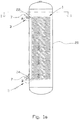
- the reference numeral 1 indicates a tubing according to the present invention for heat exchange between a first fluid which is in the tubing 1 and a second fluid which is outside the tubing 1.
- the tubing 1 has a first end portion 3 and a second end portion 5.
- the tubing 1 is arranged inside a closed tank 20.
- the tank may be, for example, a tank for heating consumption water and/or for heating buildings by means of so-called radiators or by means of a pipe system for so-called waterborne heat.
- the present invention is well suited for use together with the applicant's invention according to NO326440 .
- the first end portion 3 of the tubing 1 projects through an upper cut-out 22 in a side portion of the tank 20, whereas the second end portion 5 of the tubing 1 projects through a lower cut-out 24 in the side portion of the tank 20.
- the tubing 1 is arranged in a helix between the end portions 3, 5.
- the tubing 1 may be relatively thin-walled, for example 0.8 mm for a tubing with an external diameter of 22 mm.
- the tubing 1 is connected to a sleeve 7.
- the sleeve 7 surrounds an end portion of the tubing 1 as is shown in figure 2 showing a tubing 1 according to the prior art.
- the sleeve 7, which in this document constitutes part of the supply pipe or return pipe, has a thickness that is several times the thickness of the tubing 1.
- the internal diameter of the sleeve 7 is complementarily adapted to the external diameter of the tubing 1 so that a tight fit is provided between these when the end portion of the tubing 1 has been inserted in the sleeve 7.
- Figure 2 shows a tubing 1 which is attached to the sleeve 7 by means of a welded connection in the form of a fillet weld 9.
- Figure 2 illustrates both a typical inlet portion and a typical outlet portion for a tubing for heat exchange between a first fluid which is in the tubing 1 and a second fluid which is outside the tubing 1.
- the tubing 1 shown in figure 2 is encumbered with the considerable drawbacks that are discussed above. It is also known that instead of, or in addition to, the welded connection shown, the tubing 1 and the sleeve 7 may be connected by threads.
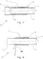
- Figure 3 shows an inlet portion of, for example, the tank 20 that is shown in figure 1 , but without the tank wall itself being shown.
- a sleeve 7 surrounds the first end portion 3 of the tubing 1.
- the tubing according to the present invention is substantially different from the prior-art tubing that is shown in figure 2 .
- the tubing 1 consists of an inner tube 1' and an outer tube 1", the outer tube 1" being arranged on the outside of the inner tube 1'.
- the end face of the inner tube 1' is adapted, in terms of length, to the outer tube 1", so that in the first end portion 3, the tubes 1', 1" substantially have the same axial extent.
- sealing means 11 One of the purposes of the sealing means 11 is to prevent fluid from entering the space between the inner tube 1' and the outer tube 1". Said fluid thus flows from the sleeve 7 into the inner tube 1' as shown by the arrow Fi in figure 3 .
- the sealing means 11 is provided by a welded connection which is shown as a butt weld in figure 3 .
- the inner tube 1' has an axial extent (not shown) different from that of the outer tube 1", for example by the outer tube 1" extending further into the sleeve 7 than the inner tube 1', a fillet weld, for example, could be used to provide a seal between the tubes 1', 1".
- the external diameter of the inner tube 1' is smaller than the internal diameter of the outer tube 1". This is necessary in order to, among other things, be able to drain any fluid, such as a liquid, that might enter the space defined by the tubes 1', 1" and the fluid-tight connection at the first end portion 3 of the tubing out through the open passage at the second end portion 1" of the tubing 1.
- the open passage will be described in more detail in what follows, in the description of figure 4 .
- Such drainage could give a warning about the inner tube 1' or the outer tube 1" being damaged.
- the warning may be provided by means of a sensor device of a kind known per se, which is arranged to be able to emit a signal on the detection of one or both of the fluids of the kind that is inside the inner tube 1' or the liquid in the tank 20.
- Figure 4 shows an outlet portion of, for example, the tank 20 that is shown in figure 1a , but without the tank wall itself being shown.
- a sleeve 7 surrounds the second end portion 5 of the tubing 1.
- the tubing 1 according to the present invention is substantially different from the prior-art tubing 1 that is shown in figure 2 .
- the end portion of the inner tube 1' has a larger axial extent than the end portion of the outer tube 1". Besides, the inner tube 1' extends through the sleeve 7 and thus projects from both end portions of the sleeve 7. The end portion of the inner tube 1' is formed with a larger diameter than the rest of the tube so that the inner tube 1' can surround a portion of a return pipe not shown.
- a sensor device 26 may sense and give a signal to a signal transceiver 26' which may give a warning that a leakage has occurred.
- a sensor device 26 and signal transceiver 26' are shown in principle in figure 4 .
- the signal from the signal transceiver 26' may be transmitted to a control device of, for example, a heat pump (not shown) or some other device providing circulation of fluid through the spiral tube 1, so that the circulation stops and the heat exchange ceases.
- a control device of, for example, a heat pump (not shown) or some other device providing circulation of fluid through the spiral tube 1, so that the circulation stops and the heat exchange ceases.
- a user may be warned in some other way, for example by means of an SMS.
- the second end portion of the tubing 1 is attached to the sleeve 7 by means of a welded connection 9 between the outer tube 1" and the end portion of the sleeve 7.
- the outer tube 1" extends only a limited distance into the sleeve 7.
- the purpose of not extending the outer tube 1" through the whole or the major part of the sleeve is to provide a smallest possible contact surface between the sleeve 7 and the outer tube 1".
- heat transfer between, for example, heated water in the tank 20 shown in figure 1 and the outside of the tank 20 will be the least possible.
- connection between the outer tube 1" and the sleeve 7 may be provided by means of, for example, a threaded connection or by means of an adhesive.
Claims (6)
- Un réservoir à chauffer un liquide, avec une tuyauterie (1), la tuyauterie étant capable d'être en communication fluidique avec
un compresseurd'un système d'échange de chaleur, la tuyauterie ayant une première partie d'extrémité (3) et une seconde partie d'extrémité (5), la tuyauterie (1) s'étendant depuis une première ouverture (22) dans une paroi du réservoir (20) jusqu'à une seconde ouverture (24) dans la paroi du réservoir (20), au moins une partie de la tuyauterie (1) s'étendant en hélice entre la première partie d'extrémité (3) et la seconde partie d'extrémité (5), la tuyauterie (1) étant agencée pour un échange de chaleur entre un premier fluide étant un source d'énergie circulant dans le système d'échange de chaleur, et un second fluide se trouvant dans le réservoir (20) à l'extérieur de la tuyauterie (1), la première partie d'extrémité (3) de la tuyauterie étant disposée au niveau de la première ouverture (22) dans le réservoir (20), et la seconde partie d'extrémité (5) étant disposée au niveau de la seconde ouverture (24) dans le réservoir (20), dans lequel la tuyauterie (1) comprend un tube intérieur lisse (1') et un tube extérieur lisse (1") qui est disposé sur le côté extérieur du tube intérieur lisse (1'), le tube intérieur (1') étant relié au tube extérieur (1") d'une manière étanche aux fluides au niveau de la première partie d'extrémité (3), la première partie d'extrémité (3) étant attachée à une conduite d'alimentation étant en communication fluidique avec le compresseur, et un passage entre le tube intérieur (1') et le tube extérieur (1") se trouvant dans la seconde partie d'extrémité (5),
un pont conducteur de chaleur étant formé entre le tube intérieur (1') et le tube extérieur (1") au niveau de la première partie d'extrémité (3), et le diamètre externe du tube intérieur (1') étant inférieur au diamètre intérieur du tube extérieur (1"), ainsi réalisant un espace entre au moins des parties du tube intérieur (1') et du tube extérieur (1") le long de la longueur entière de la tuyauterie (1) de sorte que le fluide présent entre le tube intérieur (1') et le tube extérieur (1") de la connexion étanche aux fluides au niveau de la première partie d'extrémité (3) de la tuyauterie (1) peut être mis en communication dehors à travers le passage au niveau de la seconde partie d'extrémité (5) de la tuyauterie (1), caractérisée en ce que
la première partie d'extrémité (3) est entourée par la dite conduite d'alimentation, la conduite d'alimentation étant attachée au tube extérieur (1 ") au moyen d'une soudure (9), et la connexion étanche aux fluides entre le tube intérieur (1) et le tube extérieur (1") est réalisée au moyen d'une soudure (11). - La tuyauterie (1) selon la revendication 1, dans laquelle la conduite d'alimentation (7) comprend un manchon de renforcement (7) qui est connecté au tube extérieur (1") au moyen de la soudure (9).
- La tuyauterie (1) selon l'une quelconque des revendications précédentes, dans laquelle le tube intérieur (1') est connecté à une conduite de retour de fluide au niveau de la seconde partie d'extrémité (5), et dans laquelle la conduite d'alimentation en fluide et la conduite de de retour de fluide font partie d'un circuit fermé.
- Un procédé de fabrication d'un réservoir selon la revendication 1, pour améliorer un échange de chaleur entre un premier fluide qui se trouve dans un tube intérieur (1') et un second fluide qui se trouve à l'extérieur d'un tube extérieur (1"), la majeure partie du tube extérieur (1") étant disposée à l'extérieur du tube intérieur (1'), caractérisé en ce que le procédé inclut:- former une tuyauterie en U (1) en insérant un tube intérieur lisse (1') dans un tube extérieur lisse (1"), le diamètre externe du tube intérieur (1 ") étant doté d'un diamètre inférieur au diamètre intérieur du tube extérieur (1") de sorte qu'un espace entre au moins des parties du tube intérieur (1') et du tube extérieur (1") le long de la longueur entière de la tuyauterie (1) est réalisé, la tuyauterie (1) ayant une première partie d'extrémité (3) et seconde partie d'extrémité (5), et attacher au niveau de la première partie d'extrémité (3) le tube intérieur (1') au tube extérieur (1") au moyen d'une soudure (11) pour former une connexion étanche aux fluides et dans une seconde partie d'extrémité (5) de la tuyauterie (1', 1"), maintenir un passage entre la surface intérieur du tube extérieur (1") et la surface externe du tube intérieur (1'),- insérer la première partie d'extrémité (3) de la tuyauterie en U (1) dans un manchon (7)- connecter le tube extérieur (1") au manchon (7) au moyen d'une soudure (9) connectant une partie d'extrémité du manchon (7) à une surface extérieure du tube extérieur (1"), de sorte que les connexions soudées (11, 9) et le manchon (7) réalisent un pont conducteur de chaleur depuis le tube intérieur (1') jusqu'au tube extérieur (1').
- Le procédé selon la revendication 4, dans lequel, dans la seconde partie d'extrémité (5), le tube intérieur (1') est mis en communication fluidique avec une conduite de retour de fluide.
- Le procédé selon la revendication 4 ou 5, dans lequel un dispositif capteur (26), qui répond à au moins un des fluides dans le tube intérieur (1') et sur le côté extérieur du tube extérieur (1") est connecté à un émetteur de signal.
Applications Claiming Priority (2)
| Application Number | Priority Date | Filing Date | Title |
|---|---|---|---|
| NO20131687A NO337174B1 (no) | 2013-12-19 | 2013-12-19 | Varmevekslerrør og framgangsmåte ved bruk av samme |
| PCT/NO2014/050245 WO2015093977A1 (fr) | 2013-12-19 | 2014-12-18 | Tuyauterie d'échange de chaleur et procédé d'amélioration d'échange de chaleur |
Publications (3)
| Publication Number | Publication Date |
|---|---|
| EP3084332A1 EP3084332A1 (fr) | 2016-10-26 |
| EP3084332A4 EP3084332A4 (fr) | 2017-10-18 |
| EP3084332B1 true EP3084332B1 (fr) | 2020-06-24 |
Family
ID=53403183
Family Applications (1)
| Application Number | Title | Priority Date | Filing Date |
|---|---|---|---|
| EP14873070.8A Active EP3084332B1 (fr) | 2013-12-19 | 2014-12-18 | Reservoir a chauffer une liquide avec tuyauterie d'échange de chaleur et procédé de fabrication de la meme |
Country Status (8)
| Country | Link |
|---|---|
| US (1) | US10077950B2 (fr) |
| EP (1) | EP3084332B1 (fr) |
| JP (1) | JP2017502242A (fr) |
| CN (1) | CN105849493B (fr) |
| CA (1) | CA2934347C (fr) |
| ES (1) | ES2815567T3 (fr) |
| NO (1) | NO337174B1 (fr) |
| WO (1) | WO2015093977A1 (fr) |
Families Citing this family (8)
| Publication number | Priority date | Publication date | Assignee | Title |
|---|---|---|---|---|
| SE536722C2 (sv) * | 2012-11-01 | 2014-06-17 | Skanska Sverige Ab | Energilager |
| DE102015206114A1 (de) * | 2015-04-07 | 2016-05-25 | Carl Zeiss Smt Gmbh | Kühler zur Verwendung in einer Vorrichtung im Vakuum |
| CN108036137A (zh) * | 2017-12-05 | 2018-05-15 | 苏州水博士建材科技有限公司 | 一种利用热水加热的管道结构及花洒、水龙头 |
| CN110425919B (zh) * | 2019-07-12 | 2020-12-04 | 泰兴市梅兰化工有限公司 | 一种液氯汽化器 |
| CN112524989A (zh) * | 2019-09-17 | 2021-03-19 | 光和科股份有限公司 | 用于热交换系统的连接器及其制造方法 |
| WO2023000011A1 (fr) * | 2021-07-21 | 2023-01-26 | Robert Laabmayr | Accumulateur de chaleur et échangeur de chaleur pour cet accumulateur de chaleur |
| FR3126034A1 (fr) * | 2021-08-05 | 2023-02-10 | Airbus (S.A.S.) | Echangeur thermique limitant les risques de contamination entre deux fluides et aéronef comprenant au moins un tel échangeur thermique |
| CN114485220B (zh) * | 2022-01-21 | 2024-01-02 | 江苏双立制氧机械有限公司 | 一种带有管板密封补偿结构的碳化硅列管换热器 |
Family Cites Families (24)
| Publication number | Priority date | Publication date | Assignee | Title |
|---|---|---|---|---|
| DE1501531B2 (de) * | 1965-09-22 | 1971-12-02 | Kabel- und Metallwerke Gutehoffnungshütte AG, 3000 Hannover | Mehrlagen waermeaustauscherrohr und verwendung desselben1 |
| US3934618A (en) | 1974-08-26 | 1976-01-27 | Controls Southeast, Inc. | Jacketed pipe assembly formed of corrugated metal tubes |
| DK574476A (da) * | 1976-12-21 | 1978-06-22 | H P Joergensen | Dobbeltvaegget varmeveksler |
| US4428106A (en) * | 1978-08-04 | 1984-01-31 | Uop Inc. | Method of making double wall tubing assembly |
| US4343350A (en) * | 1978-08-04 | 1982-08-10 | Uop Inc. | Double wall tubing assembly and method of making same |
| JPS56151855A (en) * | 1980-04-28 | 1981-11-25 | Hitachi Ltd | Protective apparatus for cooler/hot water feeder |
| US4328683A (en) * | 1981-01-12 | 1982-05-11 | Aluminum Company Of America | Water heating system |
| SE8107698L (en) * | 1981-12-22 | 1983-06-23 | Edgar Johansson | Heat exchanger with several pipe units - has each unit comprised of outer and inner pipes, with channel between pipes connected to pressure control |
| FR2528557A1 (fr) | 1982-06-11 | 1983-12-16 | Damois Michel | Echangeur de chaleur a detection de fuites multitubulaire rectiligne |
| US4870734A (en) | 1987-04-03 | 1989-10-03 | Tui Industries | Method of manufacturing high efficiency heat exchange tube |
| US5343937A (en) * | 1989-04-24 | 1994-09-06 | Micron Technology, Inc. | Thermal control of concentric tube liquid source gas lines |
| US6000434A (en) * | 1989-09-11 | 1999-12-14 | Dayco Products, Inc. | Flexible hose construction and method of making the same |
| US5129428A (en) * | 1989-09-11 | 1992-07-14 | Dayco Products, Inc. | Flexible hose constuction |
| US5102012A (en) * | 1990-08-31 | 1992-04-07 | Dayco Products, Inc. | Fuel dispensing system having a flexible hose with a static dissipater and a fuel leak detector |
| US5398976A (en) * | 1992-08-03 | 1995-03-21 | Environ Products, Inc. | Connecting device for pipe assemblies |
| JPH06323777A (ja) * | 1993-05-18 | 1994-11-25 | Toshiba Corp | 熱交換器とその製造方法 |
| US6131615A (en) * | 1997-10-30 | 2000-10-17 | Bundy Corporation | Tube assembly for auxiliary heating and air conditioning system |
| NL1012676C2 (nl) | 1999-07-22 | 2001-01-23 | Spiro Research Bv | Werkwijze voor het vervaardigen van een dubbelwandige warmtewisselbuis met lekdetectie alsmede een dergelijke warmtewisselbuis. |
| US7063132B2 (en) * | 2003-12-29 | 2006-06-20 | Bradford White Corporation | Multi-wall heat exchanger for a water heater |
| NO326440B1 (no) | 2006-07-14 | 2008-12-08 | Lars Hansen | Arrangement og fremgangsmate for styring av temperaturendring av fluid |
| JP2008190858A (ja) * | 2007-01-10 | 2008-08-21 | Kobelco & Materials Copper Tube Inc | 漏洩検知管 |
| JP4978301B2 (ja) * | 2007-05-09 | 2012-07-18 | パナソニック株式会社 | 熱交換器 |
| JP2011075154A (ja) | 2009-09-29 | 2011-04-14 | Daikin Industries Ltd | 熱交換ユニット |
| EP2591851A1 (fr) | 2011-11-08 | 2013-05-15 | Alfa Laval Corporate AB | Module de tuyau |
-
2013
- 2013-12-19 NO NO20131687A patent/NO337174B1/no unknown
-
2014
- 2014-12-18 US US15/103,729 patent/US10077950B2/en active Active
- 2014-12-18 ES ES14873070T patent/ES2815567T3/es active Active
- 2014-12-18 JP JP2016539996A patent/JP2017502242A/ja active Pending
- 2014-12-18 EP EP14873070.8A patent/EP3084332B1/fr active Active
- 2014-12-18 CA CA2934347A patent/CA2934347C/fr active Active
- 2014-12-18 CN CN201480068982.6A patent/CN105849493B/zh active Active
- 2014-12-18 WO PCT/NO2014/050245 patent/WO2015093977A1/fr active Application Filing
Non-Patent Citations (1)
| Title |
|---|
| None * |
Also Published As
| Publication number | Publication date |
|---|---|
| NO337174B1 (no) | 2016-02-01 |
| ES2815567T3 (es) | 2021-03-30 |
| JP2017502242A (ja) | 2017-01-19 |
| US20160320146A1 (en) | 2016-11-03 |
| US10077950B2 (en) | 2018-09-18 |
| CN105849493A (zh) | 2016-08-10 |
| EP3084332A4 (fr) | 2017-10-18 |
| CN105849493B (zh) | 2018-09-25 |
| NO20131687A1 (no) | 2015-06-22 |
| CA2934347A1 (fr) | 2015-06-25 |
| CA2934347C (fr) | 2021-10-26 |
| EP3084332A1 (fr) | 2016-10-26 |
| WO2015093977A1 (fr) | 2015-06-25 |
Similar Documents
| Publication | Publication Date | Title |
|---|---|---|
| EP3084332B1 (fr) | Reservoir a chauffer une liquide avec tuyauterie d'échange de chaleur et procédé de fabrication de la meme | |
| JP4839216B2 (ja) | 排出部内の弁を備えた分離弁 | |
| RU2616728C2 (ru) | Змеевиковый теплообменник | |
| CN111712698B (zh) | 管泄漏检测装置以及管泄漏检测方法 | |
| WO2006105370A3 (fr) | Procedes pour surveiller le salissement de systemes aqueux, y compris des tubes d'echangeur de chaleur ameliores | |
| WO2009135310A8 (fr) | Pompe autoalimentée pour liquide chauffé, réservoir de chauffage et de stockage de fluide et système de chauffage de fluide les utilisant | |
| US6837303B2 (en) | Internal water tank solar heat exchanger | |
| US4153043A (en) | Apparatus for solar hot water system and method of making same | |
| US4416222A (en) | Hot water heater circuitry | |
| RU2315247C1 (ru) | Предохранительное устройство для водогрейной системы (варианты) | |
| EP1767888A2 (fr) | Raccord pour connection d'un échangeur de chaleur | |
| JP2020501106A (ja) | 使用済み燃料プールからの液体漏れの監視システム | |
| US9022243B2 (en) | Vessel having a hose coupling | |
| CN205482535U (zh) | 单罐多管束蒸汽水浴换热器 | |
| ES2711787T3 (es) | Sistema de distribución de tubo | |
| GB1595190A (en) | Heat exchanger | |
| US20200224977A1 (en) | Heat recovery unit for gray water | |
| JP4564264B2 (ja) | 漏液発生予測方法、及び、漏液モニタ装置 | |
| TH2001004564A (th) | อุปกรณ์ตรวจหารอยรั่วของท่อและวิธีการตรวจหารอยรั่วของท่อ | |
| DK176316B1 (da) | Fremgangsmåde til fremstilling af en vandvarmer samt en vandvarmer | |
| BG106470A (bg) | Водонагревателен котел за промишлена вода | |
| CN213809495U (zh) | 带前置过滤的暖通漏水保护装置 | |
| US20180051909A1 (en) | Sealed Refrigeration System and Appliance | |
| JP2009243855A (ja) | 風呂設備 | |
| US10166420B1 (en) | Sensor reservoir with probe to monitor, measure, and control fire sprinkler and other systems and method of constructing and using the same |
Legal Events
| Date | Code | Title | Description |
|---|---|---|---|
| PUAI | Public reference made under article 153(3) epc to a published international application that has entered the european phase |
Free format text: ORIGINAL CODE: 0009012 |
|
| 17P | Request for examination filed |
Effective date: 20160607 |
|
| AK | Designated contracting states |
Kind code of ref document: A1 Designated state(s): AL AT BE BG CH CY CZ DE DK EE ES FI FR GB GR HR HU IE IS IT LI LT LU LV MC MK MT NL NO PL PT RO RS SE SI SK SM TR |
|
| AX | Request for extension of the european patent |
Extension state: BA ME |
|
| DAX | Request for extension of the european patent (deleted) | ||
| REG | Reference to a national code |
Ref country code: DE Ref legal event code: R079 Ref document number: 602014067106 Country of ref document: DE Free format text: PREVIOUS MAIN CLASS: F28D0007100000 Ipc: F28D0007020000 |
|
| A4 | Supplementary search report drawn up and despatched |
Effective date: 20170918 |
|
| RIC1 | Information provided on ipc code assigned before grant |
Ipc: F28D 20/00 20060101ALI20170912BHEP Ipc: F28D 7/02 20060101AFI20170912BHEP Ipc: F28D 1/047 20060101ALI20170912BHEP Ipc: F28D 1/02 20060101ALI20170912BHEP Ipc: F28F 1/00 20060101ALI20170912BHEP Ipc: F28F 27/00 20060101ALI20170912BHEP |
|
| GRAP | Despatch of communication of intention to grant a patent |
Free format text: ORIGINAL CODE: EPIDOSNIGR1 |
|
| STAA | Information on the status of an ep patent application or granted ep patent |
Free format text: STATUS: GRANT OF PATENT IS INTENDED |
|
| INTG | Intention to grant announced |
Effective date: 20200130 |
|
| GRAS | Grant fee paid |
Free format text: ORIGINAL CODE: EPIDOSNIGR3 |
|
| GRAA | (expected) grant |
Free format text: ORIGINAL CODE: 0009210 |
|
| STAA | Information on the status of an ep patent application or granted ep patent |
Free format text: STATUS: THE PATENT HAS BEEN GRANTED |
|
| AK | Designated contracting states |
Kind code of ref document: B1 Designated state(s): AL AT BE BG CH CY CZ DE DK EE ES FI FR GB GR HR HU IE IS IT LI LT LU LV MC MK MT NL NO PL PT RO RS SE SI SK SM TR |
|
| REG | Reference to a national code |
Ref country code: GB Ref legal event code: FG4D |
|
| REG | Reference to a national code |
Ref country code: CH Ref legal event code: EP |
|
| REG | Reference to a national code |
Ref country code: DE Ref legal event code: R096 Ref document number: 602014067106 Country of ref document: DE |
|
| REG | Reference to a national code |
Ref country code: AT Ref legal event code: REF Ref document number: 1284306 Country of ref document: AT Kind code of ref document: T Effective date: 20200715 |
|
| REG | Reference to a national code |
Ref country code: IE Ref legal event code: FG4D |
|
| REG | Reference to a national code |
Ref country code: SE Ref legal event code: TRGR |
|
| PG25 | Lapsed in a contracting state [announced via postgrant information from national office to epo] |
Ref country code: GR Free format text: LAPSE BECAUSE OF FAILURE TO SUBMIT A TRANSLATION OF THE DESCRIPTION OR TO PAY THE FEE WITHIN THE PRESCRIBED TIME-LIMIT Effective date: 20200925 Ref country code: FI Free format text: LAPSE BECAUSE OF FAILURE TO SUBMIT A TRANSLATION OF THE DESCRIPTION OR TO PAY THE FEE WITHIN THE PRESCRIBED TIME-LIMIT Effective date: 20200624 Ref country code: LT Free format text: LAPSE BECAUSE OF FAILURE TO SUBMIT A TRANSLATION OF THE DESCRIPTION OR TO PAY THE FEE WITHIN THE PRESCRIBED TIME-LIMIT Effective date: 20200624 |
|
| REG | Reference to a national code |
Ref country code: NO Ref legal event code: T2 Effective date: 20200624 |
|
| REG | Reference to a national code |
Ref country code: LT Ref legal event code: MG4D |
|
| PG25 | Lapsed in a contracting state [announced via postgrant information from national office to epo] |
Ref country code: HR Free format text: LAPSE BECAUSE OF FAILURE TO SUBMIT A TRANSLATION OF THE DESCRIPTION OR TO PAY THE FEE WITHIN THE PRESCRIBED TIME-LIMIT Effective date: 20200624 Ref country code: BG Free format text: LAPSE BECAUSE OF FAILURE TO SUBMIT A TRANSLATION OF THE DESCRIPTION OR TO PAY THE FEE WITHIN THE PRESCRIBED TIME-LIMIT Effective date: 20200924 Ref country code: RS Free format text: LAPSE BECAUSE OF FAILURE TO SUBMIT A TRANSLATION OF THE DESCRIPTION OR TO PAY THE FEE WITHIN THE PRESCRIBED TIME-LIMIT Effective date: 20200624 Ref country code: LV Free format text: LAPSE BECAUSE OF FAILURE TO SUBMIT A TRANSLATION OF THE DESCRIPTION OR TO PAY THE FEE WITHIN THE PRESCRIBED TIME-LIMIT Effective date: 20200624 |
|
| REG | Reference to a national code |
Ref country code: NL Ref legal event code: MP Effective date: 20200624 |
|
| REG | Reference to a national code |
Ref country code: AT Ref legal event code: MK05 Ref document number: 1284306 Country of ref document: AT Kind code of ref document: T Effective date: 20200624 |
|
| PG25 | Lapsed in a contracting state [announced via postgrant information from national office to epo] |
Ref country code: NL Free format text: LAPSE BECAUSE OF FAILURE TO SUBMIT A TRANSLATION OF THE DESCRIPTION OR TO PAY THE FEE WITHIN THE PRESCRIBED TIME-LIMIT Effective date: 20200624 Ref country code: AL Free format text: LAPSE BECAUSE OF FAILURE TO SUBMIT A TRANSLATION OF THE DESCRIPTION OR TO PAY THE FEE WITHIN THE PRESCRIBED TIME-LIMIT Effective date: 20200624 |
|
| PG25 | Lapsed in a contracting state [announced via postgrant information from national office to epo] |
Ref country code: PT Free format text: LAPSE BECAUSE OF FAILURE TO SUBMIT A TRANSLATION OF THE DESCRIPTION OR TO PAY THE FEE WITHIN THE PRESCRIBED TIME-LIMIT Effective date: 20201026 Ref country code: SM Free format text: LAPSE BECAUSE OF FAILURE TO SUBMIT A TRANSLATION OF THE DESCRIPTION OR TO PAY THE FEE WITHIN THE PRESCRIBED TIME-LIMIT Effective date: 20200624 Ref country code: AT Free format text: LAPSE BECAUSE OF FAILURE TO SUBMIT A TRANSLATION OF THE DESCRIPTION OR TO PAY THE FEE WITHIN THE PRESCRIBED TIME-LIMIT Effective date: 20200624 Ref country code: EE Free format text: LAPSE BECAUSE OF FAILURE TO SUBMIT A TRANSLATION OF THE DESCRIPTION OR TO PAY THE FEE WITHIN THE PRESCRIBED TIME-LIMIT Effective date: 20200624 Ref country code: RO Free format text: LAPSE BECAUSE OF FAILURE TO SUBMIT A TRANSLATION OF THE DESCRIPTION OR TO PAY THE FEE WITHIN THE PRESCRIBED TIME-LIMIT Effective date: 20200624 Ref country code: CZ Free format text: LAPSE BECAUSE OF FAILURE TO SUBMIT A TRANSLATION OF THE DESCRIPTION OR TO PAY THE FEE WITHIN THE PRESCRIBED TIME-LIMIT Effective date: 20200624 |
|
| PG25 | Lapsed in a contracting state [announced via postgrant information from national office to epo] |
Ref country code: IS Free format text: LAPSE BECAUSE OF FAILURE TO SUBMIT A TRANSLATION OF THE DESCRIPTION OR TO PAY THE FEE WITHIN THE PRESCRIBED TIME-LIMIT Effective date: 20201024 Ref country code: PL Free format text: LAPSE BECAUSE OF FAILURE TO SUBMIT A TRANSLATION OF THE DESCRIPTION OR TO PAY THE FEE WITHIN THE PRESCRIBED TIME-LIMIT Effective date: 20200624 Ref country code: SK Free format text: LAPSE BECAUSE OF FAILURE TO SUBMIT A TRANSLATION OF THE DESCRIPTION OR TO PAY THE FEE WITHIN THE PRESCRIBED TIME-LIMIT Effective date: 20200624 |
|
| REG | Reference to a national code |
Ref country code: DE Ref legal event code: R097 Ref document number: 602014067106 Country of ref document: DE |
|
| REG | Reference to a national code |
Ref country code: ES Ref legal event code: FG2A Ref document number: 2815567 Country of ref document: ES Kind code of ref document: T3 Effective date: 20210330 |
|
| PG25 | Lapsed in a contracting state [announced via postgrant information from national office to epo] |
Ref country code: DK Free format text: LAPSE BECAUSE OF FAILURE TO SUBMIT A TRANSLATION OF THE DESCRIPTION OR TO PAY THE FEE WITHIN THE PRESCRIBED TIME-LIMIT Effective date: 20200624 |
|
| PLBE | No opposition filed within time limit |
Free format text: ORIGINAL CODE: 0009261 |
|
| STAA | Information on the status of an ep patent application or granted ep patent |
Free format text: STATUS: NO OPPOSITION FILED WITHIN TIME LIMIT |
|
| 26N | No opposition filed |
Effective date: 20210325 |
|
| REG | Reference to a national code |
Ref country code: CH Ref legal event code: PL |
|
| PG25 | Lapsed in a contracting state [announced via postgrant information from national office to epo] |
Ref country code: SI Free format text: LAPSE BECAUSE OF FAILURE TO SUBMIT A TRANSLATION OF THE DESCRIPTION OR TO PAY THE FEE WITHIN THE PRESCRIBED TIME-LIMIT Effective date: 20200624 Ref country code: MC Free format text: LAPSE BECAUSE OF FAILURE TO SUBMIT A TRANSLATION OF THE DESCRIPTION OR TO PAY THE FEE WITHIN THE PRESCRIBED TIME-LIMIT Effective date: 20200624 |
|
| REG | Reference to a national code |
Ref country code: BE Ref legal event code: MM Effective date: 20201231 |
|
| PG25 | Lapsed in a contracting state [announced via postgrant information from national office to epo] |
Ref country code: IE Free format text: LAPSE BECAUSE OF NON-PAYMENT OF DUE FEES Effective date: 20201218 Ref country code: LU Free format text: LAPSE BECAUSE OF NON-PAYMENT OF DUE FEES Effective date: 20201218 |
|
| PG25 | Lapsed in a contracting state [announced via postgrant information from national office to epo] |
Ref country code: LI Free format text: LAPSE BECAUSE OF NON-PAYMENT OF DUE FEES Effective date: 20201231 Ref country code: CH Free format text: LAPSE BECAUSE OF NON-PAYMENT OF DUE FEES Effective date: 20201231 |
|
| PG25 | Lapsed in a contracting state [announced via postgrant information from national office to epo] |
Ref country code: TR Free format text: LAPSE BECAUSE OF FAILURE TO SUBMIT A TRANSLATION OF THE DESCRIPTION OR TO PAY THE FEE WITHIN THE PRESCRIBED TIME-LIMIT Effective date: 20200624 Ref country code: MT Free format text: LAPSE BECAUSE OF FAILURE TO SUBMIT A TRANSLATION OF THE DESCRIPTION OR TO PAY THE FEE WITHIN THE PRESCRIBED TIME-LIMIT Effective date: 20200624 Ref country code: CY Free format text: LAPSE BECAUSE OF FAILURE TO SUBMIT A TRANSLATION OF THE DESCRIPTION OR TO PAY THE FEE WITHIN THE PRESCRIBED TIME-LIMIT Effective date: 20200624 |
|
| PG25 | Lapsed in a contracting state [announced via postgrant information from national office to epo] |
Ref country code: MK Free format text: LAPSE BECAUSE OF FAILURE TO SUBMIT A TRANSLATION OF THE DESCRIPTION OR TO PAY THE FEE WITHIN THE PRESCRIBED TIME-LIMIT Effective date: 20200624 |
|
| PG25 | Lapsed in a contracting state [announced via postgrant information from national office to epo] |
Ref country code: BE Free format text: LAPSE BECAUSE OF NON-PAYMENT OF DUE FEES Effective date: 20201231 |
|
| PGFP | Annual fee paid to national office [announced via postgrant information from national office to epo] |
Ref country code: ES Payment date: 20230216 Year of fee payment: 9 |
|
| P01 | Opt-out of the competence of the unified patent court (upc) registered |
Effective date: 20230524 |
|
| PGFP | Annual fee paid to national office [announced via postgrant information from national office to epo] |
Ref country code: GB Payment date: 20231213 Year of fee payment: 10 |
|
| PGFP | Annual fee paid to national office [announced via postgrant information from national office to epo] |
Ref country code: SE Payment date: 20231214 Year of fee payment: 10 Ref country code: NO Payment date: 20231206 Year of fee payment: 10 Ref country code: IT Payment date: 20231120 Year of fee payment: 10 Ref country code: FR Payment date: 20231221 Year of fee payment: 10 Ref country code: DE Payment date: 20231220 Year of fee payment: 10 |
|
| PGFP | Annual fee paid to national office [announced via postgrant information from national office to epo] |
Ref country code: ES Payment date: 20240226 Year of fee payment: 10 |