EP3084046B1 - Procédé de fabrication d'une pièce revêtue d'un revêtement protecteur - Google Patents
Procédé de fabrication d'une pièce revêtue d'un revêtement protecteur Download PDFInfo
- Publication number
- EP3084046B1 EP3084046B1 EP14821803.5A EP14821803A EP3084046B1 EP 3084046 B1 EP3084046 B1 EP 3084046B1 EP 14821803 A EP14821803 A EP 14821803A EP 3084046 B1 EP3084046 B1 EP 3084046B1
- Authority
- EP
- European Patent Office
- Prior art keywords
- current
- micro
- positive
- duration
- charge applied
- Prior art date
- Legal status (The legal status is an assumption and is not a legal conclusion. Google has not performed a legal analysis and makes no representation as to the accuracy of the status listed.)
- Active
Links
- 238000000034 method Methods 0.000 title claims description 21
- 239000011253 protective coating Substances 0.000 title claims description 17
- 238000004519 manufacturing process Methods 0.000 title claims description 3
- 230000006641 stabilisation Effects 0.000 claims description 38
- 238000011105 stabilization Methods 0.000 claims description 29
- 239000003792 electrolyte Substances 0.000 claims description 25
- 238000007745 plasma electrolytic oxidation reaction Methods 0.000 claims description 24
- 239000010955 niobium Substances 0.000 claims description 20
- 229910052758 niobium Inorganic materials 0.000 claims description 16
- GUCVJGMIXFAOAE-UHFFFAOYSA-N niobium atom Chemical compound [Nb] GUCVJGMIXFAOAE-UHFFFAOYSA-N 0.000 claims description 16
- 239000011159 matrix material Substances 0.000 claims description 10
- 229910021332 silicide Inorganic materials 0.000 claims description 9
- BPQQTUXANYXVAA-UHFFFAOYSA-N Orthosilicate Chemical compound [O-][Si]([O-])([O-])[O-] BPQQTUXANYXVAA-UHFFFAOYSA-N 0.000 claims description 5
- FVBUAEGBCNSCDD-UHFFFAOYSA-N silicide(4-) Chemical compound [Si-4] FVBUAEGBCNSCDD-UHFFFAOYSA-N 0.000 claims 1
- 229910045601 alloy Inorganic materials 0.000 description 13
- 239000000956 alloy Substances 0.000 description 13
- 238000007254 oxidation reaction Methods 0.000 description 13
- PXHVJJICTQNCMI-UHFFFAOYSA-N Nickel Chemical compound [Ni] PXHVJJICTQNCMI-UHFFFAOYSA-N 0.000 description 12
- 230000003647 oxidation Effects 0.000 description 10
- 229910000601 superalloy Inorganic materials 0.000 description 7
- 239000011248 coating agent Substances 0.000 description 6
- 238000000576 coating method Methods 0.000 description 6
- 229910052751 metal Inorganic materials 0.000 description 6
- 239000002184 metal Substances 0.000 description 6
- 229910052759 nickel Inorganic materials 0.000 description 6
- 230000015572 biosynthetic process Effects 0.000 description 4
- 238000005260 corrosion Methods 0.000 description 4
- 230000007797 corrosion Effects 0.000 description 4
- 230000003247 decreasing effect Effects 0.000 description 4
- 239000000463 material Substances 0.000 description 4
- 239000000203 mixture Substances 0.000 description 4
- 150000004760 silicates Chemical class 0.000 description 4
- 239000000758 substrate Substances 0.000 description 4
- HEMHJVSKTPXQMS-UHFFFAOYSA-M Sodium hydroxide Chemical compound [OH-].[Na+] HEMHJVSKTPXQMS-UHFFFAOYSA-M 0.000 description 3
- 230000001464 adherent effect Effects 0.000 description 3
- 239000011651 chromium Substances 0.000 description 3
- 238000001816 cooling Methods 0.000 description 3
- XUIMIQQOPSSXEZ-UHFFFAOYSA-N Silicon Chemical compound [Si] XUIMIQQOPSSXEZ-UHFFFAOYSA-N 0.000 description 2
- 229910052782 aluminium Inorganic materials 0.000 description 2
- 238000002844 melting Methods 0.000 description 2
- 230000008018 melting Effects 0.000 description 2
- 230000000737 periodic effect Effects 0.000 description 2
- 239000003870 refractory metal Substances 0.000 description 2
- 238000004626 scanning electron microscopy Methods 0.000 description 2
- 229910052710 silicon Inorganic materials 0.000 description 2
- 239000010703 silicon Substances 0.000 description 2
- 239000000243 solution Substances 0.000 description 2
- 239000002904 solvent Substances 0.000 description 2
- 239000010936 titanium Substances 0.000 description 2
- XLYOFNOQVPJJNP-UHFFFAOYSA-N water Substances O XLYOFNOQVPJJNP-UHFFFAOYSA-N 0.000 description 2
- 239000010964 304L stainless steel Substances 0.000 description 1
- VYZAMTAEIAYCRO-UHFFFAOYSA-N Chromium Chemical compound [Cr] VYZAMTAEIAYCRO-UHFFFAOYSA-N 0.000 description 1
- ZOKXTWBITQBERF-UHFFFAOYSA-N Molybdenum Chemical compound [Mo] ZOKXTWBITQBERF-UHFFFAOYSA-N 0.000 description 1
- 229910000676 Si alloy Inorganic materials 0.000 description 1
- 229910004298 SiO 2 Inorganic materials 0.000 description 1
- ATJFFYVFTNAWJD-UHFFFAOYSA-N Tin Chemical compound [Sn] ATJFFYVFTNAWJD-UHFFFAOYSA-N 0.000 description 1
- RTAQQCXQSZGOHL-UHFFFAOYSA-N Titanium Chemical compound [Ti] RTAQQCXQSZGOHL-UHFFFAOYSA-N 0.000 description 1
- XAGFODPZIPBFFR-UHFFFAOYSA-N aluminium Chemical compound [Al] XAGFODPZIPBFFR-UHFFFAOYSA-N 0.000 description 1
- 239000007864 aqueous solution Substances 0.000 description 1
- QVGXLLKOCUKJST-UHFFFAOYSA-N atomic oxygen Chemical compound [O] QVGXLLKOCUKJST-UHFFFAOYSA-N 0.000 description 1
- 230000010455 autoregulation Effects 0.000 description 1
- 230000004888 barrier function Effects 0.000 description 1
- 230000008033 biological extinction Effects 0.000 description 1
- 230000015556 catabolic process Effects 0.000 description 1
- 238000005524 ceramic coating Methods 0.000 description 1
- 229910052804 chromium Inorganic materials 0.000 description 1
- 239000002131 composite material Substances 0.000 description 1
- 238000009792 diffusion process Methods 0.000 description 1
- 230000008034 disappearance Effects 0.000 description 1
- 230000000694 effects Effects 0.000 description 1
- 230000001747 exhibiting effect Effects 0.000 description 1
- 229910052735 hafnium Inorganic materials 0.000 description 1
- VBJZVLUMGGDVMO-UHFFFAOYSA-N hafnium atom Chemical compound [Hf] VBJZVLUMGGDVMO-UHFFFAOYSA-N 0.000 description 1
- 238000010438 heat treatment Methods 0.000 description 1
- 229910052750 molybdenum Inorganic materials 0.000 description 1
- 239000011733 molybdenum Substances 0.000 description 1
- LIZIAPBBPRPPLV-UHFFFAOYSA-N niobium silicon Chemical compound [Si].[Nb] LIZIAPBBPRPPLV-UHFFFAOYSA-N 0.000 description 1
- 229910052760 oxygen Inorganic materials 0.000 description 1
- 239000001301 oxygen Substances 0.000 description 1
- 239000002244 precipitate Substances 0.000 description 1
- 230000000750 progressive effect Effects 0.000 description 1
- 230000001681 protective effect Effects 0.000 description 1
- 239000007787 solid Substances 0.000 description 1
- 239000006104 solid solution Substances 0.000 description 1
- 229910052719 titanium Inorganic materials 0.000 description 1
- 230000004222 uncontrolled growth Effects 0.000 description 1
Images

Classifications
-
- C—CHEMISTRY; METALLURGY
- C25—ELECTROLYTIC OR ELECTROPHORETIC PROCESSES; APPARATUS THEREFOR
- C25D—PROCESSES FOR THE ELECTROLYTIC OR ELECTROPHORETIC PRODUCTION OF COATINGS; ELECTROFORMING; APPARATUS THEREFOR
- C25D11/00—Electrolytic coating by surface reaction, i.e. forming conversion layers
- C25D11/02—Anodisation
- C25D11/26—Anodisation of refractory metals or alloys based thereon
-
- C—CHEMISTRY; METALLURGY
- C25—ELECTROLYTIC OR ELECTROPHORETIC PROCESSES; APPARATUS THEREFOR
- C25D—PROCESSES FOR THE ELECTROLYTIC OR ELECTROPHORETIC PRODUCTION OF COATINGS; ELECTROFORMING; APPARATUS THEREFOR
- C25D11/00—Electrolytic coating by surface reaction, i.e. forming conversion layers
- C25D11/02—Anodisation
- C25D11/024—Anodisation under pulsed or modulated current or potential
-
- C—CHEMISTRY; METALLURGY
- C25—ELECTROLYTIC OR ELECTROPHORETIC PROCESSES; APPARATUS THEREFOR
- C25D—PROCESSES FOR THE ELECTROLYTIC OR ELECTROPHORETIC PRODUCTION OF COATINGS; ELECTROFORMING; APPARATUS THEREFOR
- C25D11/00—Electrolytic coating by surface reaction, i.e. forming conversion layers
- C25D11/02—Anodisation
- C25D11/026—Anodisation with spark discharge
-
- C—CHEMISTRY; METALLURGY
- C25—ELECTROLYTIC OR ELECTROPHORETIC PROCESSES; APPARATUS THEREFOR
- C25D—PROCESSES FOR THE ELECTROLYTIC OR ELECTROPHORETIC PRODUCTION OF COATINGS; ELECTROFORMING; APPARATUS THEREFOR
- C25D21/00—Processes for servicing or operating cells for electrolytic coating
- C25D21/12—Process control or regulation
Definitions
- the invention relates to parts coated with a protective coating as well as methods of making such parts.
- RMICs refractory matrix composite materials
- niobium-based alloys appear to be particularly promising in order to replace or be used in addition to existing nickel-based superalloys. These various alloys have the advantage of exhibiting higher melting points than existing superalloys. Moreover, the niobium-based alloys can also advantageously have relatively low densities (6.5-7 g / cm 3 compared to 8-9 g / cm 3 for nickel-based superalloys). Such alloys can therefore advantageously make it possible to significantly reduce the mass of parts of turbomachines, for example of high pressure turbine blades, due to their low density and their mechanical properties close to those of nickel-based superalloys at temperatures around 1100 ° C.
- Niobium-based alloys can generally contain many additional elements such as silicon (Si), titanium (Ti), chromium (Cr), aluminum (Al), hafnium (Hf), molybdenum (Mo), or tin (Sn), for example.
- These alloys have a microstructure consisting of a niobium (Nb ss ) matrix reinforced by addition elements dissolved in solid solution. This phase ensures the toughness of the alloys at low temperature. With this refractory matrix are associated precipitates of refractory metal silicides, the composition and structure of which may vary according to the addition elements (M 3 Si, M 5 Si 3 ).
- alloys can exhibit particularly advantageous mechanical properties at high temperature (T> 1100 ° C.).
- T> 1100 ° C. high temperature
- their behavior in hot oxidation can now limit their use on a large scale.
- alloys based on niobium silicides when exposed to high temperature (> 1000 ° C), they can oxidize by internal oxidation via the diffusion of oxygen through the alloy (mainly in the solution niobium solid).
- a layer may then form on the surface comprising a mixture of oxides resulting from the elements contained in the substrate.
- the oxide layer formed may be poorly adherent and unprotective due to the uncontrolled growth of unwanted oxides.
- More or less complex silicates can be formed. Without outside assistance, the silicon content in the alloys may be insufficient to generate enough silicates to develop a sufficiently protective oxide layer upon exposure to high temperature.
- the present invention relates to a method according to claim 1.
- the present invention advantageously makes it possible to achieve a self-regulatory regime during the micro-arc oxidation treatment.
- the fact of reaching such a regime is characterized by a progressive disappearance of the electric arcs when one observes with the naked eye the part subjected to the imposed cycles of current.
- the invention advantageously makes it possible to form on the surface of the part a dense protective coating of oxides which may contain a relatively high silicate content.
- a protective coating advantageously makes it possible to improve protection against oxidation and hot corrosion as well as the wear resistance of the material.
- Another advantage associated with the implementation of a treatment by micro-arc oxidation lies in the possibility of producing ceramic coatings electrochemically in aqueous solution and at low temperature.
- the ratio (amount of positive charge applied to the part) / (amount of negative charge applied to the part) may, for all or part of the current cycles, be between 0.8 and 0.9.
- the part can first be subjected to a succession of current cycles for which the ratio (amount of positive charge applied to the part) / (amount of negative charge applied to the part) is between 0.9 and 1.6, the part can then be subjected to a succession of current cycles for which the ratio ( amount of positive charge applied to the part) / (amount of negative charge applied to the part) is between 0.8 and 0.9.
- Such a modulation of the ratio (amount of positive charge applied to the part) / (amount of negative charge applied to the part) advantageously makes it possible to accelerate the formation of the protective coating.
- the ratio (amount of positive charge applied to the part) / (amount of negative charge applied to the part) may, for all or part of the current cycles, be between 0.85 and 0.90 .
- the part may, for example, comprise, in particular consist of, a niobium matrix in which inclusions of metal silicides chosen from: Nb 5 Si 3 and / or Nb 3 Si are present.
- Each current cycle includes a positive stabilization phase during which a constant current of positive intensity passes through the part, the duration of the positive stabilization phase being between 15% and 50%, for example between 17% and 23%, of the total duration of said cycle.
- Each current cycle includes a negative stabilization phase during which a constant current of negative intensity passes through the part, the duration of the negative stabilization phase being between 30% and 80%, for example between 55% and 65%, of the total duration of said cycle.
- the density of the current flowing through the part during the positive stabilization phase can be between 10 A / dm 2 and 100 A / dm 2 , for example between 50 A / dm 2 and 70 A / dm 2 .
- the density of the current flowing through the part during the negative stabilization phase can, in absolute value, be between 10 A / dm 2 and 100 A / dm 2 .
- the ratio (density of the current passing through the part during the negative stabilization phase) / (density of the current passing through the part during the positive stabilization phase) can, in absolute value, be between 30% and 80 %, for example between 50% and 60%.
- the part may be present in an electrolyte and the electrolyte may comprise, before the start of the micro-arc oxidation treatment, a silicate for example present in a concentration greater than or equal to 1 g / L, for example greater or equal to 15 g / L.
- the silicate may, before the start of the micro-arc oxidation treatment, be present in the electrolyte in a concentration of between 1 g / L and Cs where Cs denotes the limiting solubility concentration of the silicate in the electrolyte.
- Cs can, for example, be equal to 300 g / L.
- Such electrolytes advantageously make it possible to further increase the content of silicates present in the protective coating obtained and thus to further improve the corrosion resistance of the coated part.
- the electrolyte solvent can, for example, be water.
- the pH of the electrolyte can, for example, be between 10 and 14 during all or part of the micro-arc oxidation treatment.
- the part is present in an electrolyte and the electrolyte can be maintained at a temperature less than or equal to 40 ° C, for example less than or equal to 20 ° C, during all or part of the treatment by micro oxidation. -bows.
- a cooling system can help maintain the electrolyte at such temperatures. It is general knowledge of those skilled in the art to adapt the cooling carried out in order to maintain the electrolyte at these temperatures.
- the time during which the part is treated by micro-arc oxidation may be greater than or equal to 10 minutes, for example between 10 minutes and 60 minutes.
- the part can be treated by a micro-arc oxidation treatment making it possible to achieve a self-regulation regime, the self-regulation regime then being able to be maintained for a period of less than or equal to 10 minutes, for example example for a period of between 3 minutes and 10 minutes.
- each current cycle includes a positive current rise phase during which the intensity of the current flowing through the part is positive and strictly increasing, the duration of the positive current rise phase being able to be between 3% and 15%, for example between 9% and 13%, of the total duration of said cycle.
- each current cycle includes a positive current descent phase during which the intensity of the current flowing through the part is positive and strictly decreasing, the duration of the positive current descent phase being able to be between 1% and 10%, for example between 1.5% and 2.5%, of the total duration of said cycle.
- each current cycle includes a zero current stabilization phase during which the part is not traversed by any current, the duration of the zero current stabilization phase being able to be between 0.5% and 1. , 5% of the total duration of said cycle.
- each current cycle includes a negative current descent phase during which the intensity of the current flowing through the part is negative and strictly decreasing, the duration of the negative current descent phase being able to be between 1% and 10%, for example 2.5% and 3.5%, of the total duration of said cycle.
- each current cycle includes a negative current rise phase during which the intensity of the current flowing through the part is negative and strictly increasing, the duration of the negative current rise phase being able to be between 1% and 10%, for example between 1.5% and 2.5%, of the total duration of said cycle.
- the part is present in an electrolyte and the current can pass during the micro-arc oxidation treatment through the part as well as a counter-electrode present in the electrolyte, the counter-electrode having the same shape. than the room.
- a counter-electrode of shape adapted to that of the part advantageously allows for parts of relatively complex to overcome the problems of distribution of current lines. More generally, whatever the shape of the counter-electrode, the latter can be located at a distance of between 1 cm and 20 cm from the part. For example, the counter electrode is located 2.5 cm from the workpiece.
- the part is advantageous for the part to be separated from the counter-electrode by a distance less than or equal to 20 cm in order to reduce the current losses in the electrolyte and to increase the efficiency of the process.
- the cycles of current applied can be periodic.
- the frequency of the current cycles may be between 50 Hz and 1000 Hz, and for example be between 50 Hz and 150 Hz.
- the thickness of the coating formed may be greater than or equal to 20 ⁇ m, preferably 50 ⁇ m.
- the thickness of the coating formed is, for example, between 100 ⁇ m and 150 ⁇ m.
- the part can, for example, constitute a turbine engine blade.
- the part can also, for example, constitute a valve or a turbine engine distributor.
- the present invention also relates to a part coated with a protective coating capable of being obtained by implementing a method as described above as well as a turbomachine comprising such a part.
- the patent further describes the use for improving the resistance to oxidation of a part of a micro-arc oxidation treatment in which a part comprising a niobium matrix in which inclusions of metal silicides are present is subjected to a succession of current cycles, the ratio (quantity of positive charge applied to the part) / (amount of negative charge applied to the part) being, for each current cycle, between 0.80 and 1.6.
- the patent further describes the use for improving the wear resistance of a part of a micro-arc oxidation treatment in which a part comprising a niobium matrix in which inclusions of metal silicides are present is subjected to a succession of current cycles, the ratio (quantity of positive charge applied to the part) / (quantity of negative charge applied to the part) being, for each current cycle, between 0.80 and 1.6.
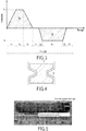
- a protective coating 3 is formed on the outer surface S of a part 2 comprising a niobium matrix in which inclusions of metal silicides are present.
- the thickness e of the coating 3 formed may, for example, be between 20 ⁇ m and 150 ⁇ m.
- FIG. 2 We represented at the figure 2 an experimental device for implementing a micro-arc oxidation treatment which can be used within the framework of the present invention.
- Part 2 is immersed in an electrolyte 10 comprising silicates.
- a counter-electrode 6 is present opposite the part 2 and is also immersed in electrolyte 10.
- counter-electrodes are present on either side of the part.
- the counter electrode 6 can, for example, be cylindrical in shape and, for example, be made of 304L stainless steel.
- the part 2 and the counter-electrode 6 are connected to a generator 5 which subjects them to a succession of current cycles.
- a first oxide layer is first formed on the external surface S of the part 2 treated.
- a sufficient current is applied in order to reach the dielectric breakdown point of the first oxide layer initially formed on the surface S of the part 2. Electric arcs are then generated and lead to the formation of a plasma on the surface S of part 2 treated.
- the protective coating 3 is then formed by converting the elements contained in the part 2 but also by incorporating elements contained in the electrolyte 10.
- the experimental device used further comprises a cooling system (not shown) making it possible to limit heating of the electrolyte during the micro-arc oxidation treatment.
- a succession of periodic current cycles is applied to part 2.
- the form of one of the applied current cycles is supplied to the figure 3 .
- the parameters are given in Table 1 shown below: ⁇ u> Table 1 ⁇ /u> I p : Intensity of the current flowing through the part during the positive stabilization phase T 1 : duration of the positive current rise phase T 2 : duration of the positive stabilization phase I n : Intensity of the current flowing through the part during the negative stabilization phase T 3 : duration of the decay phase of the positive current Q p : amount of positive charge applied to the part during the current cycle T 4 : duration of the stabilization phase at zero current T 5 : duration of the descent phase of the negative current Q n : amount of negative charge applied to the part during the current cycle T 6 : duration of the negative stabilization phase T: Period of current cycles T 7 : duration of the negative current rise phase F: Frequency of current cycles T 8 : duration of the stabilization phase at zero current
- the counter-electrode 6 can, as illustrated, have a shape similar to that of the part 2 and match its shape.
- the part and the counter-electrode can also both be of cylindrical shape or of planar shape.
- a substrate has been treated by a method according to the invention.
- Table 2 details the operating conditions below (the times are expressed in% of the total duration of the current cycle).
- the imposed cycle comprises the same succession of phases as the current cycle shown in figure 3 .
- a self-regulatory regime characterized by a gradual extinction of the electric arcs was reached after about 30 minutes of treatment.
- the sample was further treated for a further 5 minutes in an autoregulation regime so as to grow the oxide layer formed and improve its compactness.
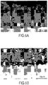
- the layer formed on the surface of the substrate was characterized by scanning electron microscopy (see figures 6A and 6B ).
- the layer formed turns out to be uniform in appearance over the entire circumference of the bar and at the level of the two areas analyzed.
- the coating formed by micro-arc anodic oxidation is perfectly adherent.
- the coating formed by micro-arc anodic oxidation is perfectly adherent.
Description
- L'invention concerne des pièces revêtues d'un revêtement protecteur ainsi que des procédés de fabrication de telles pièces.
- Actuellement au sein des parties les plus chaudes des turbomachines seuls les superalliages à base de nickel sont utilisés à l'échelle industrielle. Bien que ces superalliages à base de nickel soient revêtus d'un système de barrière thermique, leur température d'utilisation peut être limitée à 1150°C en raison de la proximité de leur point de fusion.
- De récents travaux de recherche se sont focalisés sur la mise en œuvre de nouveaux matériaux à base de métaux réfractaires capables d'être utilisés à des températures supérieures aux températures d'utilisation des superalliages à base de nickel. Ces familles de matériaux sont couramment appelées : matériaux composites à matrice réfractaire (RMICs).
- Parmi les solutions mises en évidence, les alliages à base de niobium apparaissent comme particulièrement prometteurs afin de remplacer ou d'être utilisés en complément des superalliages à base de nickel existants. Ces différents alliages ont l'avantage de présenter des points de fusion supérieurs aux superalliages existants. Par ailleurs, les alliages à base de niobium peuvent aussi avantageusement présenter des densités relativement faibles (6,5-7 g/cm3 à comparer à 8-9 g/cm3 pour les superalliages à base de nickel). De tels alliages peuvent donc avantageusement permettre de réduire significativement la masse de pièces de turbomachines, par exemple d'aubages de turbine haute pression, en raison de leur faible densité et de leurs propriétés mécaniques proches de celles des superalliages à base de nickel à des températures voisines de 1100°C.
- Les alliages à base de niobium peuvent généralement comporter de nombreux éléments d'additions tels que le silicium (Si), le titane (Ti), le chrome (Cr), l'aluminium (Al), le hafnium (Hf), le molybdène (Mo), ou l'étain (Sn), par exemple. Ces alliages présentent une microstructure constituée d'une matrice de niobium (Nbss) renforcée par des éléments d'additions dissous en solution solide. Cette phase assure la ténacité des alliages à basse température. A cette matrice réfractaire sont associés des précipités de siliciures de métaux réfractaires dont la composition et la structure peuvent varier selon les éléments d'additions (M3Si, M5Si3).
- Ces alliages peuvent présenter à haute température (T>1100°C) des propriétés mécaniques particulièrement intéressantes. Toutefois, leur comportement en oxydation à chaud peut aujourd'hui limiter leur utilisation à grande échelle. En effet, lorsque les alliages à base de siliciures de niobium sont exposés à haute température (>1000°C), ils peuvent s'oxyder par oxydation interne via la diffusion de l'oxygène au travers de l'alliage (principalement dans la solution solide de niobium). Il peut alors se former en surface une couche comportant un mélange d'oxydes issus des éléments contenus dans le substrat. La couche d'oxydes formée peut être peu adhérente et non protectrice en raison de la croissance anarchique d'oxydes non souhaités. Des silicates plus ou moins complexes peuvent être formés. Sans assistance extérieure, la teneur en silicium dans les alliages peut être insuffisante pour générer suffisamment de silicates afin de développer une couche d'oxydes suffisamment protectrice lors de l'exposition à haute température.
- On connaît en particulier
DE 10 2006 017820 qui divulgue des pièces de turbine formées d'un alliage niobium-silicium. On connaît en outreFR 2 877 018 - Il existe donc un besoin pour améliorer la résistance à la corrosion et à l'oxydation à chaud présentée par ce type d'alliages à base de niobium.
- Il existe encore un besoin pour disposer de nouveaux matériaux présentant à la fois de bonnes propriétés mécaniques (ténacité à froid et fluage à haute température pour les pièces mobiles) ainsi qu'une bonne résistance à la corrosion et à l'oxydation à haute température.
- La présente invention vise un procédé selon la revendication 1.
- La présente invention permet avantageusement d'atteindre durant le traitement par oxydation micro-arcs un régime d'autorégulation. Le fait d'atteindre un tel régime est caractérisé par une disparition progressive des arcs électriques lorsque l'on observe à l'œil nu la pièce soumise aux cycles de courant imposés.
- L'invention permet avantageusement de former à la surface de la pièce un revêtement d'oxydes protecteur dense et pouvant comporter une teneur en silicates relativement élevée. Un tel revêtement protecteur permet avantageusement d'améliorer la protection contre l'oxydation et la corrosion à chaud ainsi que la résistance à l'usure du matériau.
- Un autre avantage lié à la mise en œuvre d'un traitement par oxydation micro-arcs réside dans la possibilité de réaliser des revêtements céramiques par voie électrochimique en solution aqueuse et à basse température.
- De préférence, le rapport (quantité de charge positive appliquée à la pièce) / (quantité de charge négative appliquée à la pièce) peut, pour tout ou partie des cycles de courant, être compris entre 0,8 et 0,9.
- Dans un exemple de réalisation, la pièce peut d'abord être soumise à une succession de cycles de courant pour lesquels le rapport (quantité de charge positive appliquée à la pièce) / (quantité de charge négative appliquée à la pièce) est compris entre 0,9 et 1,6, la pièce pouvant ensuite être soumise à une succession de cycles de courant pour lesquels le rapport (quantité de charge positive appliquée à la pièce) / (quantité de charge négative appliquée à la pièce) est compris entre 0,8 et 0,9.
- Une telle modulation du rapport (quantité de charge positive appliquée à la pièce) / (quantité de charge négative appliquée à la pièce) permet avantageusement d'accélérer la formation du revêtement protecteur.
- Dans un exemple de réalisation, le rapport (quantité de charge positive appliquée à la pièce) / (quantité de charge négative appliquée à la pièce) peut, pour tout ou partie des cycles de courant, être compris entre 0,85 et 0,90.
- La pièce peut, par exemple, comporter, notamment consister en, une matrice de niobium dans laquelle sont présentes des inclusions de siliciures métalliques choisis parmi : Nb5Si3 et/ou Nb3Si.
- Chaque cycle de courant comporte une phase de stabilisation positive durant laquelle un courant constant d'intensité positive traverse la pièce, la durée de la phase de stabilisation positive étant comprise entre 15 % et 50 %, par exemple entre 17 % et 23 %, de la durée totale dudit cycle.
- Chaque cycle de courant comporte une phase de stabilisation négative durant laquelle un courant constant d'intensité négative traverse la pièce, la durée de la phase de stabilisation négative étant comprise entre 30% et 80 %, par exemple entre 55 % et 65 %, de la durée totale dudit cycle.
- Dans un exemple de réalisation, la densité du courant traversant la pièce durant la phase de stabilisation positive peut être comprise entre 10 A/dm2 et 100 A/dm2, par exemple entre 50 A/dm2 et 70 A/dm2.
- Dans un exemple de réalisation, la densité du courant traversant la pièce durant la phase de stabilisation négative peut, en valeur absolue, être comprise entre 10 A/dm2 et 100 A/dm2.
- Dans un exemple de réalisation, le rapport (densité du courant traversant la pièce durant la phase de stabilisation négative)/(densité du courant traversant la pièce durant la phase de stabilisation positive) peut, en valeur absolue, être compris entre 30 % et 80 %, par exemple entre 50 % et 60 %.
- De préférence, la pièce peut être présente dans un électrolyte et l'électrolyte peut comporter, avant le début du traitement d'oxydation micro-arcs, un silicate par exemple présent en une concentration supérieure ou égale à 1 g/L, par exemple supérieure ou égale à 15 g/L. Le silicate peut, avant le début du traitement d'oxydation micro-arcs, être présent dans l'électrolyte en une concentration comprise entre 1 g/L et Cs où Cs désigne la concentration limite de solubilité du silicate dans l'électrolyte. Cs peut, par exemple, être égal à 300 g/L.
- De tels électrolytes permettent avantageusement d'augmenter encore la teneur en silicates présents dans le revêtement protecteur obtenu et ainsi d'améliorer encore la résistance à la corrosion de la pièce revêtue.
- Le solvant de l'électrolyte peut, par exemple, être de l'eau.
- Le pH de l'électrolyte peut, par exemple, être compris entre 10 et 14 durant tout ou partie du traitement d'oxydation micro-arcs.
- Dans un exemple de réalisation, la pièce est présente dans un électrolyte et l'électrolyte peut être maintenu à une température inférieure ou égale à 40°C, par exemple inférieure ou égale à 20 °C, durant tout ou partie du traitement par oxydation micro-arcs.
- Dans ce cas, un système de refroidissement peut permettre de maintenir l'électrolyte à de telles températures. Il va des connaissances générales de l'homme du métier d'adapter le refroidissement réalisé afin de maintenir l'électrolyte à ces températures.
- Dans un exemple de réalisation, la durée pendant laquelle la pièce est traitée par oxydation micro-arcs peut être supérieure ou égale à 10 minutes, par exemple comprise entre 10 minutes et 60 minutes.
- Dans un exemple de réalisation, la pièce peut être traitée par un traitement d'oxydation micro-arcs permettant d'atteindre un régime d'autorégulation, le régime d'autorégulation pouvant alors être maintenu pendant une durée inférieure ou égale à 10 minutes, par exemple pendant une durée comprise entre 3 minutes et 10 minutes.
- Dans un exemple de réalisation, chaque cycle de courant comporte une phase de montée du courant positif durant laquelle l'intensité du courant traversant la pièce est positive et strictement croissante, la durée de la phase de montée du courant positif pouvant être comprise entre 3 % et 15 %, par exemple entre 9 % et 13 %, de la durée totale dudit cycle.
- Dans un exemple de réalisation, chaque cycle de courant comporte une phase de descente du courant positif durant laquelle l'intensité du courant traversant la pièce est positive et strictement décroissante, la durée de la phase de descente du courant positif pouvant être comprise entre 1 % et 10 %, par exemple entre 1,5 % et 2,5 %, de la durée totale dudit cycle.
- Dans un exemple de réalisation, chaque cycle de courant comporte une phase de stabilisation à courant nul durant laquelle la pièce n'est traversée par aucun courant, la durée de la phase de stabilisation à courant nul pouvant être comprise entre 0,5 % et 1,5 % de la durée totale dudit cycle.
- Dans un exemple de réalisation, chaque cycle de courant comporte une phase de descente du courant négatif durant laquelle l'intensité du courant traversant la pièce est négative et strictement décroissante, la durée de la phase de descente du courant négatif pouvant être comprise entre 1% et 10 %, par exemple 2,5 % et 3,5 %, de la durée totale dudit cycle.
- Dans un exemple de réalisation, chaque cycle de courant comporte une phase de montée du courant négatif durant laquelle l'intensité du courant traversant la pièce est négative et strictement croissante, la durée de la phase de montée du courant négatif pouvant être comprise entre 1 % et 10 %, par exemple entre 1,5 % et 2,5 %, de la durée totale dudit cycle.
- Dans un exemple de réalisation, chaque cycle de courant comporte :
- une phase de montée du courant positif durant laquelle l'intensité du courant traversant la pièce est positive et strictement croissante, la durée de la phase de montée du courant positif étant par exemple comprise entre 3 % et 15 %, par exemple entre 9 % et 13 %, de la durée totale dudit cycle, puis
- une phase de stabilisation positive durant laquelle un courant constant d'intensité positive traverse la pièce, la durée de la phase de stabilisation positive étant comprise entre 15 % et 50 %, par exemple entre 17 % et 23 %, de la durée totale dudit cycle, puis
- une phase de descente du courant positif durant laquelle l'intensité du courant traversant la pièce est positive et strictement décroissante, la durée de la phase de descente du courant positif étant, par exemple, comprise entre 1 % et 10 %, par exemple entre 1,5 % et 2,5 %, de la durée totale dudit cycle, puis
- éventuellement une phase de stabilisation à courant nul durant laquelle la pièce n'est traversée par aucun courant, la durée de la phase de stabilisation à courant nul pouvant être comprise entre 0,5 % et 1,5 % de la durée totale dudit cycle, puis
- une phase de descente du courant négatif durant laquelle l'intensité du courant traversant la pièce est négative et strictement décroissante, la durée de la phase de descente du courant négatif étant, par exemple, comprise entre 1% et 10 %, par exemple 2,5 % et 3,5 %, de la durée totale dudit cycle, puis
- une phase de stabilisation négative durant laquelle un courant constant d'intensité négative traverse la pièce, la durée de la phase de stabilisation négative étant comprise entre 30 % et 80 %, par exemple entre 55 % et 65 %, de la durée totale dudit cycle, puis
- une phase de montée du courant négatif durant laquelle l'intensité du courant traversant la pièce est négative et strictement croissante, la durée de la phase de montée du courant négatif étant, par exemple, comprise entre 1 % et 10 %, par exemple entre 1,5 % et 2,5 %, de la durée totale dudit cycle.
- Dans un exemple de réalisation, la pièce est présente dans un électrolyte et le courant peut traverser durant le traitement d'oxydation micro-arcs la pièce ainsi qu'une contre-électrode présente dans l'électrolyte, la contre-électrode ayant la même forme que la pièce.
- L'utilisation d'une contre-électrode de forme adaptée à celle de la pièce permet avantageusement pour des pièces de forme relativement complexe de s'affranchir des problèmes de répartition des lignes de courant. Plus généralement, quelle que soit la forme de la contre-électrode, celle-ci peut être située à une distance comprise entre 1 cm et 20 cm de la pièce. Par exemple, la contre-électrode est située à 2,5 cm de la pièce.
- Il est avantageux que la pièce soit séparée de la contre-électrode par une distance inférieure ou égale à 20 cm afin de diminuer les pertes de courant dans l'électrolyte et d'augmenter l'efficacité du procédé. En outre, il est avantageux que la pièce soit séparée de la contre-électrode par une distance supérieure ou égale à 1 cm afin de limiter l'impact des effets de bord.
- Dans un exemple de réalisation, les cycles de courant appliqués peuvent être périodiques. Dans un exemple de réalisation, la fréquence des cycles de courant peut être comprise entre 50 Hz et 1000 Hz, et par exemple être comprise entre 50 Hz et 150 Hz.
- L'épaisseur du revêtement formé peut être supérieure ou égale à 20 µm, de préférence à 50 µm. L'épaisseur du revêtement formé est, par exemple, comprise entre 100 µm et 150 µm.
- La pièce peut, par exemple, constituer une aube de turbomachine. La pièce peut encore, par exemple, constituer une vanne ou un distributeur de turbomachine.
- La présente invention vise également une pièce revêtue par un revêtement protecteur susceptible d'être obtenue par mise en œuvre d'un procédé tel que décrit plus haut ainsi qu'une turbomachine comportant une telle pièce.
- Le brevet décrit encore l'utilisation pour améliorer la résistance à l'oxydation d'une pièce d'un traitement d'oxydation micro-arcs dans lequel une pièce comportant une matrice de niobium dans laquelle des inclusions de siliciures métalliques sont présentes est soumise à une succession de cycles de courant, le rapport (quantité de charge positive appliquée à la pièce) / (quantité de charge négative appliquée à la pièce) étant, pour chaque cycle de courant, compris entre 0,80 et 1,6.
- Le brevet décrit encore l'utilisation pour améliorer la résistance à l'usure d'une pièce d'un traitement d'oxydation micro-arcs dans lequel une pièce comportant une matrice de niobium dans laquelle des inclusions de siliciures métalliques sont présentes est soumise à une succession de cycles de courant, le rapport (quantité de charge positive appliquée à la pièce) / (quantité de charge négative appliquée à la pièce) étant, pour chaque cycle de courant, compris entre 0,80 et 1,6.
- Le brevet décrit encore un procédé de fabrication d'une pièce revêtue d'un revêtement protecteur, le procédé comportant l'étape suivante :
- formation par traitement d'oxydation micro-arcs d'un revêtement protecteur sur la surface externe d'une pièce, la pièce comportant une matrice de niobium dans laquelle des inclusions de siliciures métalliques sont présentes, un régime d'autorégulation étant atteint durant le traitement d'oxydation micro-arcs.
- Les caractéristiques et avantages décrits plus haut s'appliquent à ce dernier aspect de l'invention.
- D'autres caractéristiques et avantages de l'invention ressortiront de la description suivante de modes particuliers de réalisation de l'invention, donnés à titre d'exemples non limitatifs, en référence aux dessins annexés, sur lesquels :
- la
figure 1 représente, de manière schématique et partielle, une section d'une pièce revêtue par un revêtement protecteur obtenue par mise en œuvre d'un procédé selon l'invention, - la
figure 2 représente de manière schématique et partielle un dispositif expérimental pour la mise en œuvre d'un procédé selon l'invention, - la
figure 3 représente de manière schématique un exemple de cycle de courant utilisable dans un traitement d'oxydation micro-arcs selon l'invention, - la
figure 4 représente de manière schématique et partielle une variante de réalisation d'une contre-électrode utilisable dans le cadre d'un procédé selon l'invention, - la
figure 5 est une photographie du résultat obtenu après traitement par un procédé selon l'invention d'une pièce comportant une matrice de niobium dans laquelle des inclusions de siliciures métalliques sont présentes, et - les
figures 6A et 6B sont des observations en section par microscopie électronique à balayage du revêtement protecteur formé à la surface de la pièce de lafigure 5 . - On a représenté, à la
figure 1 , une section d'une pièce 1 revêtue d'un revêtement protecteur. Un revêtement protecteur 3 est formé sur la surface externe S d'une pièce 2 comportant une matrice de niobium dans laquelle des inclusions de siliciures métalliques sont présentes. - L'épaisseur e du revêtement 3 formé peut, par exemple, être comprise entre 20 µm et 150 µm.
- On a représenté à la
figure 2 un dispositif expérimental pour la mise en œuvre d'un traitement d'oxydation micro-arcs utilisable dans le cadre de la présente invention. La pièce 2 est immergée dans un électrolyte 10 comportant des silicates. Une contre-électrode 6 est présente en regard de la pièce 2 et est elle aussi immergée dans l'électrolyte 10. Dans une variante non illustrée, des contre-électrodes sont présentes de part et d'autre de la pièce. La contre-électrode 6 peut, par exemple, être de forme cylindrique et, par exemple, être constituée d'un acier inoxydable 304L. La pièce 2 et la contre-électrode 6 sont reliées à un générateur 5 lequel les soumet à une succession de cycles de courant. - Lors de la mise en œuvre du procédé selon l'invention, une première couche d'oxyde se forme tout d'abord sur la surface externe S de la pièce 2 traitée. Un courant suffisant est appliqué afin d'atteindre le point de claquage diélectrique de la première couche d'oxyde initialement formée à la surface S de la pièce 2. Des arcs électriques sont alors générés et conduisent à la formation d'un plasma en surface S de la pièce 2 traitée. Le revêtement protecteur 3 est alors formé par conversion des éléments contenus dans la pièce 2 mais aussi par incorporation d'éléments contenus dans l'électrolyte 10. Le dispositif expérimental utilisé comporte, en outre, un système de refroidissement (non représenté) permettant de limiter l'échauffement de l'électrolyte durant le traitement d'oxydation micro-arcs.
- On applique à la pièce 2 une succession de cycles de courant périodiques. La forme d'un des cycles de courant appliqué est fournie à la
figure 3 . Les paramètres sont donnés dans le tableau 1 figurant ci-dessous :Tableau 1 Ip : Intensité du courant traversant la pièce durant la phase de stabilisation positive T1 : durée de la phase de montée du courant positif T2 : durée de la phase de stabilisation positive In : Intensité du courant traversant la pièce durant la phase de stabilisation négative T3 : durée de la phase de descente du courant positif Qp : quantité de charge positive appliquée à la pièce durant le cycle de courant T4 : durée de la phase de stabilisation à courant nul T5 : durée de la phase de descente du courant négatif Qn : quantité de charge négative appliquée à la pièce durant le cycle de courant T6 : durée de la phase de stabilisation négative T : Période des cycles de courant T7 : durée de la phase de montée du courant négatif F : Fréquence des cycles de courant T8 : durée de la phase de stabilisation à courant nul - Comme illustré à la
figure 3 , chacun des cycles de courant appliqués peut comporter la succession suivante de phases : - phase de montée du courant positif, puis
- phase de stabilisation positive, puis
- phase de descente du courant positif, puis
- éventuellement phase de stabilisation à courant nul, puis
- phase de descente du courant négatif, puis
- phase de stabilisation négative, puis
- phase de montée du courant négatif.
- La durée totale du cycle de courant correspond à la somme suivante :

- On a représenté à la
figure 4 une variante de réalisation dans laquelle la contre-électrode 6 a une forme adaptée à celle de la pièce 2. - La contre-électrode 6 peut, comme illustré, avoir une forme similaire à celle de la pièce 2 et épouser sa forme. La pièce et la contre-électrode peuvent encore être toutes les deux de forme cylindrique ou de forme plane.
- Un substrat a été traité par un procédé selon l'invention. Le tableau 2 détaille ci-dessous les conditions opératoires (les temps sont exprimés en % de la durée totale du cycle de courant). Le cycle imposé comporte la même succession de phases que le cycle de courant représenté à la
figure 3 .Tableau 2 Paramètres électriques Composition de l'électrolyte avant le début du traitement d'oxydation micro-arcs Composition du substrat de base avant le début du traitement d'oxydation micro-arcs (%atomique) : alliage MASC (décrit dans US 5942055 )I (A) = 11 NaOH = 0,4 g/L Nb = 47% R = In/Ip = 55% Na2SiO2,5H2O = 15g/L Ti = 25 % Fréquence = 100 Hz pH 12-13 Hf = 8 % Qp/Qn = 0,87 solvant = eau Cr = 2 % T1 =11% Al = 2 % T2 = 20 % Si = 16 % T3 = 2 % T4 = 1 % T5 = 3 % T6 = 61 % T7 = 2 % - Un régime d'autorégulation caractérisé par une extinction progressive des arcs électriques a été atteint après environ 30 minutes de traitement. L'échantillon a encore traité 5 minutes supplémentaires en régime d'autorégulation de manière à faire croître la couche d'oxyde formée et améliorer sa compacité.
- Ces conditions opératoires ont avantageusement permis de former un revêtement protecteur relativement dense d'épaisseur environ égale à 150 µm à la surface de l'éprouvette traitée.
- Après traitement, le barreau apparait parfaitement revêtu. Son aspect macroscopique est donné à la
figure 5 . - La couche formée à la surface du substrat a été caractérisée par microscopie électronique à balayage (voir
figures 6A et 6B ). La couche formée s'avère d'un aspect uniforme sur l'ensemble de la circonférence du barreau et au niveau des deux zones analysées. - Le revêtement formé par oxydation anodique micro-arcs est parfaitement adhérent.
- L'expression « comportant/contenant un(e) » doit se comprendre comme « comportant/contenant au moins un(e) ».
- L'expression « compris(e) entre ... et ... » ou « allant de ... à ... » doit se comprendre comme incluant les bornes.
- Le revêtement formé par oxydation anodique micro-arcs est parfaitement adhérent.
- L'expression « comportant/contenant un(e) » doit se comprendre comme « comportant/contenant au moins un(e) ».
- L'expression « compris(e) entre ... et ... » ou « allant de ... à ... » doit se comprendre comme incluant les bornes.
Claims (8)
- Procédé de fabrication d'une pièce (1) revêtue d'un revêtement protecteur, le procédé comportant l'étape suivante :- formation par traitement d'oxydation micro-arcs d'un revêtement protecteur (3) sur la surface externe (S) d'une pièce (2), la pièce (2) comportant une matrice de niobium dans laquelle des inclusions de siliciures métalliques sont présentes, le courant traversant la pièce (2) étant contrôlé durant le traitement d'oxydation micro-arcs afin de soumettre la pièce (2) à une succession de cycles de courant, le rapport (quantité de charge positive appliquée à la pièce) / (quantité de charge négative appliquée à la pièce) étant, pour chaque cycle de courant, compris entre 0,80 et 1,6,dans lequel chaque cycle de courant comporte :- une phase de stabilisation positive durant laquelle un courant constant d'intensité positive (Ip) traverse la pièce, la durée de la phase de stabilisation positive (T2) étant comprise entre 15 % et 50 % de la durée totale dudit cycle, et- une phase de stabilisation négative durant laquelle un courant constant d'intensité négative (In) traverse la pièce, la durée de la phase de stabilisation négative (T6) étant comprise entre 30 % et 80 % de la durée totale dudit cycle.
- Procédé selon la revendication 1, caractérisé en ce que la pièce (2) est présente dans un électrolyte (10) et en ce que l'électrolyte (10) comporte, avant le début du traitement d'oxydation micro-arcs, un silicate.
- Procédé selon la revendication 1 ou 2, caractérisé en ce que la pièce (2) est présente dans un électrolyte (10) et en ce que l'électrolyte (10) est maintenu à une température inférieure ou égale à 40°C durant tout ou partie du traitement par oxydation micro-arcs.
- Procédé selon l'une quelconque des revendications 1 à 3, caractérisé en ce que la pièce (2) est présente dans un électrolyte (10) et en ce que le courant traverse durant le traitement d'oxydation micro-arcs la pièce (2) ainsi qu'une contre-électrode (6) présente dans l'électrolyte (10), la contre-électrode (6) ayant la même forme que la pièce (2).
- Procédé selon l'une quelconque des revendications 1 à 4, caractérisé en ce que la durée pendant laquelle la pièce (2) est traitée par oxydation micro-arcs est supérieure ou égale à 10 minutes.
- Procédé selon l'une quelconque des revendications 1 à 5, caractérisé en ce que la pièce (2) est traitée par un traitement d'oxydation micro-arcs permettant d'atteindre un régime d'autorégulation, ledit régime d'autorégulation étant alors maintenu pendant une durée comprise entre 3 minutes et 10 minutes.
- Procédé selon l'une quelconque des revendications 1 à 6, caractérisé en ce que le rapport (quantité de charge positive appliquée à la pièce) / (quantité de charge négative appliquée à la pièce) est, pour tout ou partie des cycles de courant, compris entre 0,8 et 0,9.
- Procédé selon l'une quelconque des revendications 1 à 7, caractérisé en ce que la pièce (2) est d'abord soumise à une succession de cycles de courant pour lesquels le rapport (quantité de charge positive appliquée à la pièce) / (quantité de charge négative appliquée à la pièce) est compris entre 0,9 et 1,6, la pièce étant ensuite soumise à une succession de cycles de courant pour lesquels le rapport (quantité de charge positive appliquée à la pièce) / (quantité de charge négative appliquée à la pièce) est compris entre 0,8 et 0,9.
Applications Claiming Priority (2)
| Application Number | Priority Date | Filing Date | Title |
|---|---|---|---|
| FR1362707A FR3014912B1 (fr) | 2013-12-16 | 2013-12-16 | Procede de fabrication d'une piece revetue d'un revetement protecteur |
| PCT/FR2014/053206 WO2015092205A1 (fr) | 2013-12-16 | 2014-12-08 | Procédé de fabrication d'une pièce revêtue d'un revêtement protecteur |
Publications (2)
| Publication Number | Publication Date |
|---|---|
| EP3084046A1 EP3084046A1 (fr) | 2016-10-26 |
| EP3084046B1 true EP3084046B1 (fr) | 2020-07-22 |
Family
ID=50489233
Family Applications (1)
| Application Number | Title | Priority Date | Filing Date |
|---|---|---|---|
| EP14821803.5A Active EP3084046B1 (fr) | 2013-12-16 | 2014-12-08 | Procédé de fabrication d'une pièce revêtue d'un revêtement protecteur |
Country Status (7)
| Country | Link |
|---|---|
| US (1) | US10233558B2 (fr) |
| EP (1) | EP3084046B1 (fr) |
| JP (1) | JP6509869B2 (fr) |
| CN (1) | CN105829584B (fr) |
| CA (1) | CA2933952C (fr) |
| FR (1) | FR3014912B1 (fr) |
| WO (1) | WO2015092205A1 (fr) |
Families Citing this family (3)
| Publication number | Priority date | Publication date | Assignee | Title |
|---|---|---|---|---|
| CN108368632B (zh) * | 2015-12-16 | 2020-09-25 | 汉高股份有限及两合公司 | 用于在铝上沉积钛基保护涂层的方法 |
| FR3110605B1 (fr) | 2020-05-20 | 2023-06-30 | Lag2M | Procede et installation de traitement de pieces metalliques par oxydation micro-arc |
| FR3111146A1 (fr) | 2021-06-03 | 2021-12-10 | Lag2M | Installation de traitement de pieces metalliques par oxydation micro-arc |
Family Cites Families (15)
| Publication number | Priority date | Publication date | Assignee | Title |
|---|---|---|---|---|
| US3956080A (en) * | 1973-03-01 | 1976-05-11 | D & M Technologies | Coated valve metal article formed by spark anodizing |
| US5720866A (en) * | 1996-06-14 | 1998-02-24 | Ara Coating, Inc. | Method for forming coatings by electrolyte discharge and coatings formed thereby |
| AT1669U1 (de) * | 1996-11-22 | 1997-09-25 | Plansee Ag | Oxidationsschutzschicht für refraktärmetalle |
| KR20020042642A (ko) * | 1999-08-17 | 2002-06-05 | 추후제출 | 경합금계 복합 재료 보호용 다기능 코팅 |
| JP3321600B2 (ja) * | 1999-11-25 | 2002-09-03 | 独立行政法人産業技術総合研究所 | 高耐酸化性Nb−Al−Si系金属間化合物 |
| JP2001226734A (ja) | 2000-02-15 | 2001-08-21 | Chokoon Zairyo Kenkyusho:Kk | ニオブ基複合材料およびその製造方法 |
| US20060016690A1 (en) * | 2004-07-23 | 2006-01-26 | Ilya Ostrovsky | Method for producing a hard coating with high corrosion resistance on articles made anodizable metals or alloys |
| FR2877018B1 (fr) * | 2004-10-25 | 2007-09-21 | Snecma Moteurs Sa | Procede d'oxydation micro arc pour la fabrication d'un revetement sur un substrat metallique, et son utilisation |
| WO2005118919A1 (fr) * | 2004-11-05 | 2005-12-15 | Nihon Parkerizing Co., Ltd. | Procédé de revêtement céramique électrolytique pour métal, électrolyte pour utilisation dans un revêtement céramique électrolytique pour métal et materiau de metal |
| DE102006017820A1 (de) * | 2006-04-13 | 2007-10-18 | General Electric Co. | Zusammensetzungen auf Niob-Siliziumbasis und entsprechende Gegenstände |
| CN101605929B (zh) * | 2006-09-27 | 2011-11-09 | Zypro株式会社 | 陶瓷被覆金属材料及其制造方法 |
| EP2371996B1 (fr) * | 2008-12-26 | 2016-03-09 | Nihon Parkerizing Co., Ltd. | Procédé de revêtement électrolytique céramique pour métaux, solution d'électrolyse pour revêtement électrolytique céramique, et matériau métallique |
| CA2824541A1 (fr) * | 2011-02-08 | 2012-08-16 | Cambridge Nanotherm Limited | Substrat metallique isole |
| CN102877104A (zh) * | 2012-10-09 | 2013-01-16 | 西南石油大学 | 一种低压快速微弧氧化技术 |
| CN103233257B (zh) * | 2013-03-27 | 2015-05-27 | 西南石油大学 | 一种微弧氧化膜掺杂金属氧化物的制备技术 |
-
2013
- 2013-12-16 FR FR1362707A patent/FR3014912B1/fr active Active
-
2014
- 2014-12-08 CN CN201480068205.1A patent/CN105829584B/zh active Active
- 2014-12-08 WO PCT/FR2014/053206 patent/WO2015092205A1/fr active Application Filing
- 2014-12-08 US US15/104,457 patent/US10233558B2/en active Active
- 2014-12-08 JP JP2016539954A patent/JP6509869B2/ja active Active
- 2014-12-08 CA CA2933952A patent/CA2933952C/fr active Active
- 2014-12-08 EP EP14821803.5A patent/EP3084046B1/fr active Active
Non-Patent Citations (1)
| Title |
|---|
| None * |
Also Published As
| Publication number | Publication date |
|---|---|
| US20170002476A1 (en) | 2017-01-05 |
| FR3014912B1 (fr) | 2016-01-01 |
| CN105829584A (zh) | 2016-08-03 |
| CA2933952C (fr) | 2022-02-22 |
| WO2015092205A1 (fr) | 2015-06-25 |
| JP6509869B2 (ja) | 2019-05-08 |
| JP2016540894A (ja) | 2016-12-28 |
| CA2933952A1 (fr) | 2015-06-25 |
| CN105829584B (zh) | 2019-11-05 |
| EP3084046A1 (fr) | 2016-10-26 |
| FR3014912A1 (fr) | 2015-06-19 |
| US10233558B2 (en) | 2019-03-19 |
Similar Documents
| Publication | Publication Date | Title |
|---|---|---|
| WO2016042262A1 (fr) | Gaine de combustible nucléaire composite, procédé de fabrication et utilisations contre l'oxydation/ hydruration | |
| EP3084046B1 (fr) | Procédé de fabrication d'une pièce revêtue d'un revêtement protecteur | |
| EP3161187B1 (fr) | Matériau d'électrode et son utilisation pour la fabrication d'anode inerte | |
| EP3377680B1 (fr) | Pièce de moteur d'aéronef comportant un revêtement de protection contre l'érosion et procédé de fabrication d'une telle pièce | |
| FR2593114A1 (fr) | Materiau composite stratifie muni d'une couche d'arret de diffusion, en particulier pour elements de glissement et de frottement, et procede pour sa fabrication. | |
| FR3030577B1 (fr) | Alliage intermetallique a base de titane | |
| EP3277855B1 (fr) | Matériau cermet d'electrode | |
| EP3469111B1 (fr) | Procédé de fabrication d'une pièce en superalliage à base de nickel contenant de l'hafnium | |
| EP3227468B1 (fr) | Procédé de fabrication d'une pièce revêtue d'un revêtement protecteur | |
| EP3320287B1 (fr) | Procédé de traitement thermique d'une préforme en poudre en alliage à base de titane | |
| EP3287857B1 (fr) | Procédé d'obtention d'un article à base de zircone ayant un aspect métallique | |
| CH515622A (fr) | Ensemble électrode-électrolyte pour pile à combustible à électrolyte solide fonctionnant à haute température et procédé pour sa fabrication | |
| EP3109339B1 (fr) | Procede de traitement d'une pièce en tantale ou en un alliage de tantale | |
| FR2974659A1 (fr) | Conducteur thermique a faible temperature | |
| EP0885980B1 (fr) | Procédé pour la formation, par traitement thermochimique sans plasma, d'une couche superficielle présentant une dureté élevée | |
| FR3031989A1 (fr) | Procede de traitement d'une piece et piece comportant un revetement | |
| FR3071272B1 (fr) | Piece de turbine en superalliage comprenant du rhenium et/ou du ruthenium et procede de fabrication associe | |
| WO2023161576A1 (fr) | Poudre d'alliage, procédé de fabrication d'une pièce à base de cet alliage et pièce ainsi obtenue | |
| FR3113254A1 (fr) | Protection contre l’oxydation ou la corrosion d’une pièce creuse en superalliage | |
| WO2023161577A1 (fr) | Poudre d'alliage, procédé de fabrication d'une pièce à base de cet alliage et pièce ainsi obtenue | |
| WO2018114963A1 (fr) | Procede de traitement chimique d'une paroi reduisant la formation de coke. | |
| OA18425A (fr) | Matériau cermet d'électrode. | |
| FR3051806A1 (fr) | Procede de chromage par voie electrolytique d'un substrat a partir d'un bain de chrome trivalent | |
| FR2974658A1 (fr) | Materiau de cablage pour aimant supraconducteur |
Legal Events
| Date | Code | Title | Description |
|---|---|---|---|
| PUAI | Public reference made under article 153(3) epc to a published international application that has entered the european phase |
Free format text: ORIGINAL CODE: 0009012 |
|
| 17P | Request for examination filed |
Effective date: 20160608 |
|
| AK | Designated contracting states |
Kind code of ref document: A1 Designated state(s): AL AT BE BG CH CY CZ DE DK EE ES FI FR GB GR HR HU IE IS IT LI LT LU LV MC MK MT NL NO PL PT RO RS SE SI SK SM TR |
|
| AX | Request for extension of the european patent |
Extension state: BA ME |
|
| DAX | Request for extension of the european patent (deleted) | ||
| STAA | Information on the status of an ep patent application or granted ep patent |
Free format text: STATUS: EXAMINATION IS IN PROGRESS |
|
| 17Q | First examination report despatched |
Effective date: 20180322 |
|
| RAP1 | Party data changed (applicant data changed or rights of an application transferred) |
Owner name: SAFRAN AIRCRAFT ENGINES |
|
| GRAP | Despatch of communication of intention to grant a patent |
Free format text: ORIGINAL CODE: EPIDOSNIGR1 |
|
| STAA | Information on the status of an ep patent application or granted ep patent |
Free format text: STATUS: GRANT OF PATENT IS INTENDED |
|
| INTG | Intention to grant announced |
Effective date: 20200303 |
|
| GRAS | Grant fee paid |
Free format text: ORIGINAL CODE: EPIDOSNIGR3 |
|
| GRAA | (expected) grant |
Free format text: ORIGINAL CODE: 0009210 |
|
| STAA | Information on the status of an ep patent application or granted ep patent |
Free format text: STATUS: THE PATENT HAS BEEN GRANTED |
|
| AK | Designated contracting states |
Kind code of ref document: B1 Designated state(s): AL AT BE BG CH CY CZ DE DK EE ES FI FR GB GR HR HU IE IS IT LI LT LU LV MC MK MT NL NO PL PT RO RS SE SI SK SM TR |
|
| REG | Reference to a national code |
Ref country code: GB Ref legal event code: FG4D Free format text: NOT ENGLISH |
|
| REG | Reference to a national code |
Ref country code: CH Ref legal event code: EP |
|
| REG | Reference to a national code |
Ref country code: DE Ref legal event code: R096 Ref document number: 602014068082 Country of ref document: DE |
|
| REG | Reference to a national code |
Ref country code: AT Ref legal event code: REF Ref document number: 1293469 Country of ref document: AT Kind code of ref document: T Effective date: 20200815 |
|
| REG | Reference to a national code |
Ref country code: IE Ref legal event code: FG4D Free format text: LANGUAGE OF EP DOCUMENT: FRENCH |
|
| REG | Reference to a national code |
Ref country code: SE Ref legal event code: TRGR |
|
| REG | Reference to a national code |
Ref country code: LT Ref legal event code: MG4D |
|
| REG | Reference to a national code |
Ref country code: AT Ref legal event code: MK05 Ref document number: 1293469 Country of ref document: AT Kind code of ref document: T Effective date: 20200722 |
|
| PG25 | Lapsed in a contracting state [announced via postgrant information from national office to epo] |
Ref country code: PT Free format text: LAPSE BECAUSE OF FAILURE TO SUBMIT A TRANSLATION OF THE DESCRIPTION OR TO PAY THE FEE WITHIN THE PRESCRIBED TIME-LIMIT Effective date: 20201123 Ref country code: AT Free format text: LAPSE BECAUSE OF FAILURE TO SUBMIT A TRANSLATION OF THE DESCRIPTION OR TO PAY THE FEE WITHIN THE PRESCRIBED TIME-LIMIT Effective date: 20200722 Ref country code: BG Free format text: LAPSE BECAUSE OF FAILURE TO SUBMIT A TRANSLATION OF THE DESCRIPTION OR TO PAY THE FEE WITHIN THE PRESCRIBED TIME-LIMIT Effective date: 20201022 Ref country code: LT Free format text: LAPSE BECAUSE OF FAILURE TO SUBMIT A TRANSLATION OF THE DESCRIPTION OR TO PAY THE FEE WITHIN THE PRESCRIBED TIME-LIMIT Effective date: 20200722 Ref country code: FI Free format text: LAPSE BECAUSE OF FAILURE TO SUBMIT A TRANSLATION OF THE DESCRIPTION OR TO PAY THE FEE WITHIN THE PRESCRIBED TIME-LIMIT Effective date: 20200722 Ref country code: HR Free format text: LAPSE BECAUSE OF FAILURE TO SUBMIT A TRANSLATION OF THE DESCRIPTION OR TO PAY THE FEE WITHIN THE PRESCRIBED TIME-LIMIT Effective date: 20200722 Ref country code: GR Free format text: LAPSE BECAUSE OF FAILURE TO SUBMIT A TRANSLATION OF THE DESCRIPTION OR TO PAY THE FEE WITHIN THE PRESCRIBED TIME-LIMIT Effective date: 20201023 Ref country code: ES Free format text: LAPSE BECAUSE OF FAILURE TO SUBMIT A TRANSLATION OF THE DESCRIPTION OR TO PAY THE FEE WITHIN THE PRESCRIBED TIME-LIMIT Effective date: 20200722 Ref country code: NO Free format text: LAPSE BECAUSE OF FAILURE TO SUBMIT A TRANSLATION OF THE DESCRIPTION OR TO PAY THE FEE WITHIN THE PRESCRIBED TIME-LIMIT Effective date: 20201022 |
|
| PG25 | Lapsed in a contracting state [announced via postgrant information from national office to epo] |
Ref country code: IS Free format text: LAPSE BECAUSE OF FAILURE TO SUBMIT A TRANSLATION OF THE DESCRIPTION OR TO PAY THE FEE WITHIN THE PRESCRIBED TIME-LIMIT Effective date: 20201122 Ref country code: LV Free format text: LAPSE BECAUSE OF FAILURE TO SUBMIT A TRANSLATION OF THE DESCRIPTION OR TO PAY THE FEE WITHIN THE PRESCRIBED TIME-LIMIT Effective date: 20200722 Ref country code: RS Free format text: LAPSE BECAUSE OF FAILURE TO SUBMIT A TRANSLATION OF THE DESCRIPTION OR TO PAY THE FEE WITHIN THE PRESCRIBED TIME-LIMIT Effective date: 20200722 Ref country code: PL Free format text: LAPSE BECAUSE OF FAILURE TO SUBMIT A TRANSLATION OF THE DESCRIPTION OR TO PAY THE FEE WITHIN THE PRESCRIBED TIME-LIMIT Effective date: 20200722 |
|
| PG25 | Lapsed in a contracting state [announced via postgrant information from national office to epo] |
Ref country code: NL Free format text: LAPSE BECAUSE OF FAILURE TO SUBMIT A TRANSLATION OF THE DESCRIPTION OR TO PAY THE FEE WITHIN THE PRESCRIBED TIME-LIMIT Effective date: 20200722 |
|
| REG | Reference to a national code |
Ref country code: DE Ref legal event code: R097 Ref document number: 602014068082 Country of ref document: DE |
|
| PG25 | Lapsed in a contracting state [announced via postgrant information from national office to epo] |
Ref country code: SM Free format text: LAPSE BECAUSE OF FAILURE TO SUBMIT A TRANSLATION OF THE DESCRIPTION OR TO PAY THE FEE WITHIN THE PRESCRIBED TIME-LIMIT Effective date: 20200722 Ref country code: RO Free format text: LAPSE BECAUSE OF FAILURE TO SUBMIT A TRANSLATION OF THE DESCRIPTION OR TO PAY THE FEE WITHIN THE PRESCRIBED TIME-LIMIT Effective date: 20200722 Ref country code: EE Free format text: LAPSE BECAUSE OF FAILURE TO SUBMIT A TRANSLATION OF THE DESCRIPTION OR TO PAY THE FEE WITHIN THE PRESCRIBED TIME-LIMIT Effective date: 20200722 Ref country code: DK Free format text: LAPSE BECAUSE OF FAILURE TO SUBMIT A TRANSLATION OF THE DESCRIPTION OR TO PAY THE FEE WITHIN THE PRESCRIBED TIME-LIMIT Effective date: 20200722 Ref country code: CZ Free format text: LAPSE BECAUSE OF FAILURE TO SUBMIT A TRANSLATION OF THE DESCRIPTION OR TO PAY THE FEE WITHIN THE PRESCRIBED TIME-LIMIT Effective date: 20200722 |
|
| PLBE | No opposition filed within time limit |
Free format text: ORIGINAL CODE: 0009261 |
|
| STAA | Information on the status of an ep patent application or granted ep patent |
Free format text: STATUS: NO OPPOSITION FILED WITHIN TIME LIMIT |
|
| PG25 | Lapsed in a contracting state [announced via postgrant information from national office to epo] |
Ref country code: AL Free format text: LAPSE BECAUSE OF FAILURE TO SUBMIT A TRANSLATION OF THE DESCRIPTION OR TO PAY THE FEE WITHIN THE PRESCRIBED TIME-LIMIT Effective date: 20200722 |
|
| 26N | No opposition filed |
Effective date: 20210423 |
|
| PG25 | Lapsed in a contracting state [announced via postgrant information from national office to epo] |
Ref country code: SK Free format text: LAPSE BECAUSE OF FAILURE TO SUBMIT A TRANSLATION OF THE DESCRIPTION OR TO PAY THE FEE WITHIN THE PRESCRIBED TIME-LIMIT Effective date: 20200722 |
|
| REG | Reference to a national code |
Ref country code: CH Ref legal event code: PL |
|
| PG25 | Lapsed in a contracting state [announced via postgrant information from national office to epo] |
Ref country code: SI Free format text: LAPSE BECAUSE OF FAILURE TO SUBMIT A TRANSLATION OF THE DESCRIPTION OR TO PAY THE FEE WITHIN THE PRESCRIBED TIME-LIMIT Effective date: 20200722 Ref country code: MC Free format text: LAPSE BECAUSE OF FAILURE TO SUBMIT A TRANSLATION OF THE DESCRIPTION OR TO PAY THE FEE WITHIN THE PRESCRIBED TIME-LIMIT Effective date: 20200722 |
|
| REG | Reference to a national code |
Ref country code: BE Ref legal event code: MM Effective date: 20201231 |
|
| REG | Reference to a national code |
Ref country code: NL Ref legal event code: MP Effective date: 20200722 |
|
| PG25 | Lapsed in a contracting state [announced via postgrant information from national office to epo] |
Ref country code: IE Free format text: LAPSE BECAUSE OF NON-PAYMENT OF DUE FEES Effective date: 20201208 Ref country code: LU Free format text: LAPSE BECAUSE OF NON-PAYMENT OF DUE FEES Effective date: 20201208 |
|
| PG25 | Lapsed in a contracting state [announced via postgrant information from national office to epo] |
Ref country code: LI Free format text: LAPSE BECAUSE OF NON-PAYMENT OF DUE FEES Effective date: 20201231 Ref country code: CH Free format text: LAPSE BECAUSE OF NON-PAYMENT OF DUE FEES Effective date: 20201231 |
|
| PG25 | Lapsed in a contracting state [announced via postgrant information from national office to epo] |
Ref country code: TR Free format text: LAPSE BECAUSE OF FAILURE TO SUBMIT A TRANSLATION OF THE DESCRIPTION OR TO PAY THE FEE WITHIN THE PRESCRIBED TIME-LIMIT Effective date: 20200722 Ref country code: MT Free format text: LAPSE BECAUSE OF FAILURE TO SUBMIT A TRANSLATION OF THE DESCRIPTION OR TO PAY THE FEE WITHIN THE PRESCRIBED TIME-LIMIT Effective date: 20200722 Ref country code: CY Free format text: LAPSE BECAUSE OF FAILURE TO SUBMIT A TRANSLATION OF THE DESCRIPTION OR TO PAY THE FEE WITHIN THE PRESCRIBED TIME-LIMIT Effective date: 20200722 |
|
| PG25 | Lapsed in a contracting state [announced via postgrant information from national office to epo] |
Ref country code: MK Free format text: LAPSE BECAUSE OF FAILURE TO SUBMIT A TRANSLATION OF THE DESCRIPTION OR TO PAY THE FEE WITHIN THE PRESCRIBED TIME-LIMIT Effective date: 20200722 |
|
| PG25 | Lapsed in a contracting state [announced via postgrant information from national office to epo] |
Ref country code: BE Free format text: LAPSE BECAUSE OF NON-PAYMENT OF DUE FEES Effective date: 20201231 |
|
| PGFP | Annual fee paid to national office [announced via postgrant information from national office to epo] |
Ref country code: IT Payment date: 20221122 Year of fee payment: 9 |
|
| PGFP | Annual fee paid to national office [announced via postgrant information from national office to epo] |
Ref country code: GB Payment date: 20231121 Year of fee payment: 10 |
|
| PGFP | Annual fee paid to national office [announced via postgrant information from national office to epo] |
Ref country code: SE Payment date: 20231121 Year of fee payment: 10 Ref country code: FR Payment date: 20231122 Year of fee payment: 10 Ref country code: DE Payment date: 20231121 Year of fee payment: 10 |