EP3083006B1 - Indicateur de la qualité de l'air - Google Patents
Indicateur de la qualité de l'air Download PDFInfo
- Publication number
- EP3083006B1 EP3083006B1 EP14872182.2A EP14872182A EP3083006B1 EP 3083006 B1 EP3083006 B1 EP 3083006B1 EP 14872182 A EP14872182 A EP 14872182A EP 3083006 B1 EP3083006 B1 EP 3083006B1
- Authority
- EP
- European Patent Office
- Prior art keywords
- air
- indicator
- filter medium
- air filter
- air flow
- Prior art date
- Legal status (The legal status is an assumption and is not a legal conclusion. Google has not performed a legal analysis and makes no representation as to the accuracy of the status listed.)
- Not-in-force
Links
Images


Classifications
-
- B—PERFORMING OPERATIONS; TRANSPORTING
- B01—PHYSICAL OR CHEMICAL PROCESSES OR APPARATUS IN GENERAL
- B01D—SEPARATION
- B01D46/00—Filters or filtering processes specially modified for separating dispersed particles from gases or vapours
- B01D46/0084—Filters or filtering processes specially modified for separating dispersed particles from gases or vapours provided with safety means
- B01D46/0086—Filter condition indicators
-
- B—PERFORMING OPERATIONS; TRANSPORTING
- B01—PHYSICAL OR CHEMICAL PROCESSES OR APPARATUS IN GENERAL
- B01D—SEPARATION
- B01D46/00—Filters or filtering processes specially modified for separating dispersed particles from gases or vapours
- B01D46/0027—Filters or filtering processes specially modified for separating dispersed particles from gases or vapours with additional separating or treating functions
- B01D46/0032—Filters or filtering processes specially modified for separating dispersed particles from gases or vapours with additional separating or treating functions using electrostatic forces to remove particles, e.g. electret filters
-
- B—PERFORMING OPERATIONS; TRANSPORTING
- B01—PHYSICAL OR CHEMICAL PROCESSES OR APPARATUS IN GENERAL
- B01D—SEPARATION
- B01D46/00—Filters or filtering processes specially modified for separating dispersed particles from gases or vapours
- B01D46/56—Filters or filtering processes specially modified for separating dispersed particles from gases or vapours with multiple filtering elements, characterised by their mutual disposition
- B01D46/58—Filters or filtering processes specially modified for separating dispersed particles from gases or vapours with multiple filtering elements, characterised by their mutual disposition connected in parallel
-
- F—MECHANICAL ENGINEERING; LIGHTING; HEATING; WEAPONS; BLASTING
- F24—HEATING; RANGES; VENTILATING
- F24F—AIR-CONDITIONING; AIR-HUMIDIFICATION; VENTILATION; USE OF AIR CURRENTS FOR SCREENING
- F24F11/00—Control or safety arrangements
- F24F11/30—Control or safety arrangements for purposes related to the operation of the system, e.g. for safety or monitoring
- F24F11/32—Responding to malfunctions or emergencies
- F24F11/39—Monitoring filter performance
-
- F—MECHANICAL ENGINEERING; LIGHTING; HEATING; WEAPONS; BLASTING
- F24—HEATING; RANGES; VENTILATING
- F24F—AIR-CONDITIONING; AIR-HUMIDIFICATION; VENTILATION; USE OF AIR CURRENTS FOR SCREENING
- F24F11/00—Control or safety arrangements
- F24F11/50—Control or safety arrangements characterised by user interfaces or communication
- F24F11/52—Indication arrangements, e.g. displays
-
- F—MECHANICAL ENGINEERING; LIGHTING; HEATING; WEAPONS; BLASTING
- F24—HEATING; RANGES; VENTILATING
- F24F—AIR-CONDITIONING; AIR-HUMIDIFICATION; VENTILATION; USE OF AIR CURRENTS FOR SCREENING
- F24F8/00—Treatment, e.g. purification, of air supplied to human living or working spaces otherwise than by heating, cooling, humidifying or drying
- F24F8/10—Treatment, e.g. purification, of air supplied to human living or working spaces otherwise than by heating, cooling, humidifying or drying by separation, e.g. by filtering
- F24F8/108—Treatment, e.g. purification, of air supplied to human living or working spaces otherwise than by heating, cooling, humidifying or drying by separation, e.g. by filtering using dry filter elements
-
- F—MECHANICAL ENGINEERING; LIGHTING; HEATING; WEAPONS; BLASTING
- F24—HEATING; RANGES; VENTILATING
- F24F—AIR-CONDITIONING; AIR-HUMIDIFICATION; VENTILATION; USE OF AIR CURRENTS FOR SCREENING
- F24F8/00—Treatment, e.g. purification, of air supplied to human living or working spaces otherwise than by heating, cooling, humidifying or drying
- F24F8/10—Treatment, e.g. purification, of air supplied to human living or working spaces otherwise than by heating, cooling, humidifying or drying by separation, e.g. by filtering
- F24F8/192—Treatment, e.g. purification, of air supplied to human living or working spaces otherwise than by heating, cooling, humidifying or drying by separation, e.g. by filtering by electrical means, e.g. by applying electrostatic fields or high voltages
-
- G—PHYSICS
- G01—MEASURING; TESTING
- G01N—INVESTIGATING OR ANALYSING MATERIALS BY DETERMINING THEIR CHEMICAL OR PHYSICAL PROPERTIES
- G01N1/00—Sampling; Preparing specimens for investigation
- G01N1/02—Devices for withdrawing samples
- G01N1/22—Devices for withdrawing samples in the gaseous state
- G01N1/2202—Devices for withdrawing samples in the gaseous state involving separation of sample components during sampling
- G01N1/2205—Devices for withdrawing samples in the gaseous state involving separation of sample components during sampling with filters
-
- G—PHYSICS
- G01—MEASURING; TESTING
- G01N—INVESTIGATING OR ANALYSING MATERIALS BY DETERMINING THEIR CHEMICAL OR PHYSICAL PROPERTIES
- G01N15/00—Investigating characteristics of particles; Investigating permeability, pore-volume, or surface-area of porous materials
- G01N15/06—Investigating concentration of particle suspensions
- G01N15/0606—Investigating concentration of particle suspensions by collecting particles on a support
- G01N15/0618—Investigating concentration of particle suspensions by collecting particles on a support of the filter type
- G01N15/0625—Optical scan of the deposits
-
- B—PERFORMING OPERATIONS; TRANSPORTING
- B01—PHYSICAL OR CHEMICAL PROCESSES OR APPARATUS IN GENERAL
- B01D—SEPARATION
- B01D2267/00—Multiple filter elements specially adapted for separating dispersed particles from gases or vapours
- B01D2267/40—Different types of filters
-
- F—MECHANICAL ENGINEERING; LIGHTING; HEATING; WEAPONS; BLASTING
- F24—HEATING; RANGES; VENTILATING
- F24F—AIR-CONDITIONING; AIR-HUMIDIFICATION; VENTILATION; USE OF AIR CURRENTS FOR SCREENING
- F24F2110/00—Control inputs relating to air properties
- F24F2110/50—Air quality properties
-
- G—PHYSICS
- G01—MEASURING; TESTING
- G01N—INVESTIGATING OR ANALYSING MATERIALS BY DETERMINING THEIR CHEMICAL OR PHYSICAL PROPERTIES
- G01N15/00—Investigating characteristics of particles; Investigating permeability, pore-volume, or surface-area of porous materials
- G01N2015/0042—Investigating dispersion of solids
- G01N2015/0046—Investigating dispersion of solids in gas, e.g. smoke
-
- Y—GENERAL TAGGING OF NEW TECHNOLOGICAL DEVELOPMENTS; GENERAL TAGGING OF CROSS-SECTIONAL TECHNOLOGIES SPANNING OVER SEVERAL SECTIONS OF THE IPC; TECHNICAL SUBJECTS COVERED BY FORMER USPC CROSS-REFERENCE ART COLLECTIONS [XRACs] AND DIGESTS
- Y02—TECHNOLOGIES OR APPLICATIONS FOR MITIGATION OR ADAPTATION AGAINST CLIMATE CHANGE
- Y02B—CLIMATE CHANGE MITIGATION TECHNOLOGIES RELATED TO BUILDINGS, e.g. HOUSING, HOUSE APPLIANCES OR RELATED END-USER APPLICATIONS
- Y02B30/00—Energy efficient heating, ventilation or air conditioning [HVAC]
- Y02B30/70—Efficient control or regulation technologies, e.g. for control of refrigerant flow, motor or heating
Definitions
- the present disclosure relates to air quality indicators. More particularly, it relates to easy-to-use indicators of elevated airborne fine particle levels.
- Air quality is a rising concern in many parts of the world.
- One air quality parameter of heightened interest is the levels or amount of fine particles of fine particulate matter.
- Fine particles or fine particulate matter is commonly designated as particles having a diameter of 2.5 ⁇ m or less, and is conventionally referred to by the abbreviation "PM 2.5 ". Airborne fine particles can pose significant health risks, especially at elevated levels in relatively confined areas.
- WO 00/03787 describes a change indicator for a filter for use in a gaseous circulation system.
- the change indicator includes an air impervious patch secured to the filter causing a pressure drop so that less of contaminants accumulate next to the patch while contaminants are deposited at the periphery of the air filter.
- the accumulation of contaminants inwardly from the region adjacent the periphery of the change indicator towards the region adjacent to the center is an indication that the air filter needs cleaning or replacement.
- Electret nonwoven webs are mentioned as filter medium.
- an air quality indicator for providing an indication of high fine particle levels in air.
- the indicator includes a frame maintaining first and second air filter media.
- the first air filter medium includes an electret nonwoven web.
- the second air filter medium includes an uncharged nonwoven web.
- the first air filter medium differs from the second air filter medium at least in terms of a change in visual appearance (e.g., color) when subjected to air flow containing fine particles.
- the first air filter medium is a high efficiency filter medium (e.g., highly electrostatically charged) and the second air filter medium is a low efficiency filter medium (uncharged).
- Combining the high and low efficiency media into an indicator can provide an indicator with two parallel loading surfaces that initially appear similar (or identical) but which change color at a differential rate when exposed to contaminated air.
- the indicator can thus provide information about the quality of the air in the location sampled, and can inform a user as to the benefits of adding an electrostatically charged filter medium for improving indoor air quality of the environment. Treatments which improve the durability of electrostatic charge toward oily contaminants, such as surface fluorination, may be beneficial in particularly contaminated air.
- Active airflow through the indicator can be beneficial in some embodiments to appreciably produce a distinct change in visual appearance of the first air filter medium.
- air-moving devices to which such an indicator may be attached include an air purifier inlet or upstream side of a filter, an HVAC upstream side of a filter, a portable fan, the inlet side of a room or portable air conditioner, and the supply or return duct for an HVAC system.
- the indicator may also be supplied with its own air-moving device.
- the air quality indicator may commonly cover only a portion, often a small portion, of one of the air-moving surfaces mentioned above. As such, the indicator acts as a partial barrier to air flowing through the overall air-moving surface. The air will want to preferentially flow around, not through, the air quality indicator. Thus, the ability to provide high efficiency but very low pressure drop media for the indicator is optionally important, in some embodiments, to allowing adequate air flow through the indicator to properly indicate the air quality.
- a method according to claim 6 of indicating existence of high fine particle levels in air is used downstream of an HVAC filter.
- an indicator may be used downstream of a low efficiency (such as an uncharged medium) filter to indicate to the consumer that their filter has not filtered a significant portion of particles in the air, but that an electrostatic filter may deliver improved filtration to their space.
- a low efficiency filter such as an uncharged medium
- This approach may be particularly favorable since the upstream filter, even if low efficiency for fine particles, will likely catch much of the very large particulate matter that might constitute a "false positive" dirty appearance at the indicator.
- the air quality indicator 20 includes a frame 22 maintaining a first air filter medium 24 and a second air filter medium 26. Details on the various components are provided below.
- the frame 22 is relatively small, and retains the filter media 24, 26 in a side-by-side arrangement.
- the first and second air filter media 24, 26 can assume a variety of forms, and are both generally capable of allowing air flow through a thickness thereof (i.e., into and out of the page of FIG. 1 ).
- the first air filter medium 24 differs from the second air filter medium 26 at least in terms of a rate of change in visual appearance when subjected to fine particle-laden air flow over a relatively short period of time (e.g., on the order of 1 - 10 days).
- the change in visual appearance in response to air flow with elevated PM 2.5 characteristic can be a function of an ability of the air filter media 24, 26 to capture fine particles (e.g., the first air filter medium 24 can readily capture fine particles, whereas the second filter medium 26 captures fine particles to a much lesser extent, if at all).
- the air quality indicator 20 can be located in an environment of interest, for example at a location of prevalent forced air flow. Under circumstances where the air flow contains higher levels of fine particles, over time a visual appearance of the first air filter medium 24 will become distinct from a visual appearance of the second air filter medium 26, thus apprising a user that elevated fine particle levels exist in the environment.
- the frame 22 can assume a wide variety of forms, and is generally configured to robustly retain the filter media 24, 26 in the presence of expected air flow rates (e.g., on the order of 02. to 2.0 meters per second).
- the frame 22 can be made of paperboard, cardboard, corrugated fiber board, plastic, corrugated plastic, or other inexpensive material. Alternatively, the frame 22 can be constructed from a more rigid material, such as metal.
- the frame 22 forms or defines a pair of windows 28, 30 at which the filter media 24, 26, respectively, are retained. Thus, the filter media 24, 26 are exposed to an external environment of the indicator 20, and more particularly air flow, at the windows 28, 30.
- the frame 22 defines an overall footprint of the indicator 20 and is relatively small, for example having a length of not more than 15.24 cm (6 inches), alternatively not more than 10.16 cm (4 inches), alternatively on the order of 7.62 cm (3 inches); a width of not more than 10.16 cm (4 inches), alternatively not more than 5.08 cm (2 inches), alternatively on the order of 2.54 cm (1 inch). Other dimensions (e.g., a length greater than 15.24 cm (6 inches) and/or a width greater than 10.16 cm (4 inches)) are also envisioned. Further, while the frame 22 is illustrated as having a rectangular-shaped perimeter, other shapes are also acceptable (e.g., square, circle, irregular, etc.).
- a small size or footprint of the frame 22, and thus of the indicator 20 can be characterized by reference to a surface area of the indicator 20, for example a surface area of not more than 24 in 2 , alternatively not more than 16 in 2 , alternatively not more than 10 in 2 , and in some embodiments on the order of 3 in 2 .
- the frame 22 is desirably simple in shape and construction so as to render the indicator 20 inexpensive and easy to manufacture in some embodiments.
- the frame 22 can incorporate, or have assembled thereto, one or more additional components that promote mounting of the indicator 20 at a desired location.
- a major face of the frame 22 can include or be coated with a pressure sensitive adhesive or other adhesive composition.
- one or more fasteners e.g., hook, VelcroTM, etc.
- hook, VelcroTM, etc. can be assembled to or provided at one of the major faces of the frame 22.
- the frame 22 has been described as being an integrally formed component, other constructions are envisioned.
- the frame 22 can consist of two or more sections that are separately formed and subsequently assembled (e.g., when mounting the frame 22 to the air filter media 24, 26).
- the first and second air filter media 24, 26 can each be formed with or assembled to a frame or housing, with the two air filter medium frames or housings being subsequently assembled to one another to collectively define the singular frame 22.
- FIG. 1A illustrates one optional embodiment indicator 20' including a frame 22' and the air filter media 24, 26.
- the frame 22' is configured to maintain the air filter media 24, 26 as described elsewhere, and is further configured to direct air flow to the media 24, 26 while maintaining the media 24, 26 at a convenient viewing location relative to an installation site, such as the air inlet of a split air condition.
- the frame 22' can be configured to be assembled by a user from a flat state ( FIG. 1B ) to the final state of FIG. 1A .
- the frame 22' defines a front panel 32, opposing side panels 34 (one of which is visible in FIG. 1A ), and a top panel 36.
- the panels 32-36 combine to define an inlet 38 (referenced generally in FIG. 1A ) that is assembled over an active air flow surface, with the panels 32-36 directing the air flow to the air filter media 24, 26.
- Frames of the present disclosure can have a number of other shapes and constructions.
- the first and second air filter media 24, 26 are in some respects similar, capable of permitting air flow there through (very low pressure drop) and constructed of a generally similar base material as described below. Moreover, prior to exposure to air flow (e.g., prior to use of the indicator 20), the air filter media 24, 26 can have a similar visual appearance, such as a similar color (e.g., white, off-white, etc.). However, the first air filter medium 24 is highly efficient in capturing fine particles, whereas as the second air filter medium 26 exhibits, at best, low efficiency.
- the captured fine particles coat the surface of the individual fibers of the first air filter medium 24 and cause a darkening of the entire filter medium 24 over time; the same fine particles do not readily collect on the second air filter medium 26 such that the second air filter medium 26 will exhibit minimal, if any, color change (due to presence of fine particles) over time.
- a white pigment (or other color) can be incorporated into each of the media 24, 26 to provide a more distinct "starting" color or appearance (e.g., a white pigment such as titanium dioxide is included or added to the media 24, 26 at acceptable amounts (e.g., 0.1 to 1.0% by mass) to effectuate a more dramatic change in color in the first air filter medium 24, and a more distinct difference in color between the first and second media 24, 26 as the first air filter medium 24 becomes coated with fine particles).
- a white pigment such as titanium dioxide is included or added to the media 24, 26 at acceptable amounts (e.g., 0.1 to 1.0% by mass) to effectuate a more dramatic change in color in the first air filter medium 24, and a more distinct difference in color between the first and second media 24, 26 as the first air filter medium 24 becomes coated with fine particles).
- the first air filter medium 24 can assume a variety of forms presently known, or in the future developed, constructed or formatted as a high efficiency filter medium (i.e., highly efficient in capturing fine particles).
- the high efficiency attribute is obtained by imparting an electrostatic charge into or on to material(s) of the first air filter medium 24.
- the first air filter medium 24 includes a nonwoven fiber web as is known to those of ordinary skill, and is provided with an electrostatic charge and is referred to as an electret nonwoven web.
- Nonwoven webs useful with the first air filter medium 24 can be formed from a plurality of fibers; as described below, an electrostatic charge can be imparted into the fibers prior to formation of the nonwoven web (e.g., the electret web is formed from electret fibers), or the fibers may not have an electrostatic charge prior to formation of the nonwoven web (with the electrostatic charge being imparted after formation of the web).
- the nonwoven web may have random fiber arrangement and generally isotropic in-plane physical properties (e.g., tensile strength), or if desired may have aligned fiber construction (e.g., one in which the fibers are aligned in the machine direction as described in U.S. Patent No. 6,858,297 to Shah et al. ) and anisotropic in-plane physical properties.
- isotropic in-plane physical properties e.g., tensile strength
- aligned fiber construction e.g., one in which the fibers are aligned in the machine direction as described in U.S. Patent No. 6,858,297 to Shah et al.
- polymeric fiber-forming materials may be used as the base material of the first air filter medium 24.
- the polymer may be essentially any thermoplastic fiber-forming material capable of providing a nonwoven web that will maintain satisfactory electret properties or charge separation.
- Some preferred polymeric fiber-forming materials for chargeable webs are non-conductive resins having a volume resistivity of 10 14 ohm-centimeters or greater.
- Polymeric fiber-forming materials for use in chargeable webs can optionally be substantially free from components such as antistatic agents that could significantly increase electrical conductivity or otherwise interfere with the fiber's ability to accept and hold electrostatic charges.
- polymers which may be used in chargeable webs include thermoplastic polymers containing polyolefins such as polyethylene, polypropylene, polybutylene poly(4-methyl-1-pentene), cyclic olefin copolymers, polyesters such as polylactic acid, and combinations of such polymers.
- the fibers are prepared from polypropylene homopolymer because of its ability to retain electric charge, particularly in moist environments.
- Additives may be added to the polymer to enhance the web's ability to attain and maintain satisfactory electret properties, mechanical properties, aging properties, coloring, surface properties or other characteristics of interest.
- Representative additives include fillers, nucleating agents (e.g., MILLADTM 3988 dibenzylidene sorbitol, commercially available from Milliken Chemical), electret charging enhancement additives (e.g., tristearyl melamine, and various light stabilizers such as CHIMASSORBTM 119 and CHIMASSORB 944 from Ciba Specialty Chemicals), cure initiators, stiffening agents (e.g., poly(4-methyl-1-pentene)), surface active agents and surface treatments (e.g., fluorine atom treatments to improve filtration performance in oily mist environments as described in U.S.
- nucleating agents e.g., MILLADTM 3988 dibenzylidene sorbitol, commercially available from Milliken Chemical
- electret charging enhancement additives
- Patent Nos. 6,398,847 , 6,397,458 , and 6,409,806 to Jones et al. Other electrostatic charging additives include those described in U.S. Patent Nos. 6,268,496 , 5,976,208 , 5,968,635 , 5,919,847 , and 5,909,598 , and U.S. Patent Application Publication No. 2012/0017910 .
- the types and amounts of such additives will be familiar to those skilled in the art.
- electret charging enhancement additives are generally present in an amount less than about 5 wt. % and more typically less than about 2 wt. %.
- some or all of the fibers comprising the nonwoven webs useful with the first air filter medium 24 are multicomponent fibers having at least a first region and a second region, wherein the first region has a melting temperature lower that the second region.
- multicomponent fibers are described in, for example, U.S. Patent Nos. 7,695,660 , 6,057,256 , 5,486,410 , 5,662,728 , and 5,972,808 .
- the multicomponent fibers can be bicomponent fibers, one of example of which is a sheath/core fiber where the sheath that surrounds the core forms the first region and the core forms the second region of the fiber.
- Another example of bicomponent fibers useful with the present disclosure are low density bicomponent fibers described, for example, in U.S. Patent No. 5,597,645 .
- Nonwoven webs useful with the first air filter medium 24 can be a high loft spunbond web, such as described, for example, in U.S. Patent No. 8,162,153 to Fox et al. .
- the first air filter medium 24 can be a low loft spunbond web, such as those described in U.S. Patent No. 7,947,142 to Fox et al. .
- nonwoven webs useful with the first air filter medium 24 are generated by other techniques and/or have other characteristics, such as the meltblown nonwoven webs disclosed in U.S. Patent No. 6,858,297 to Shah et al. (mentioned above).
- Other non-limiting example of useful nonwoven web formats include bi-modal fiber diameter meltblown media such as those described in U.S. Patent No. 7,858,163 .
- Electric charge can be imparted to the nonwoven webs of the first air filter medium 24 in a variety of ways.
- the fibers can be electrostatically charged before, during and/or after being formed into a nonwoven web. This may be carried out, for example, by contacting the fibers and/or the web with water as disclosed in U.S. Patent No. 5,496,507 to Angadjivand et al , corona-treating as disclosed in U.S. Patent No. 4,588,537 to Klasse et al. , hydro-charging as disclosed, for example, in U.S. Patent No. 5,908,598 to Rousseau et al. , plasma treating as disclosed in U.S. Patent No.
- the nonwoven web useful as the first air filter medium 24 may be subjected to a charging process that further enhances any charges possessed by the electret fibers and/or may enhance the ability of the fibers to maintain these charges.
- electret fibers may be subjected to an initial charging process prior to web formation; and, an additional (final) charging process may be formed on the web in order to reach the desired final charge state of the electret fibers.
- the nonwoven webs useful with the first air filter medium 24 may comprises fibers that, although they may comprise e.g., electret charging enhancement additives, did not go through a charging process prior to the fibers being formed into a web.
- the post-web-formation charging process may include e.g., any or all of corona charging, tribocharging, hydrocharging, corona treatment followed by hydrocharging, and plasma treatment followed by hydrocharging.
- Such a charging process might be performed e.g., before or after application of a support layer to the nonwoven electret web (thus, in some embodiments, some degree of charging may be imparted to the material of the support layer(s)).
- Electret filter webs useful as the first air filter medium 24 can be formed of split fibrillated charged fibers such as described in U.S. Patent No. RE 30,782 to Van Turnhout et al. .
- the electret fibers of this reference are formed from a corona charged film that is fibrillated to form the charged fibers.
- the charged fibers can then be formed into a nonwoven web by common methods such as carding or air laying.
- the so-provided nonwoven web can optionally be joined (e.g., needle tacked) to a supporting scrim such as disclosed in U.S. Patent No. 5,230,800 , forming an outer support layer.
- the first air filter medium 24 thus includes the electret nonwoven web and the support layer.
- the fibrillated film can be ultrasonically bonded to a supporting scrim such as disclosed in U.S. Patent Application Publication No. 2004/0011204 to Both .
- the second air filter medium 26 can be any low efficiency air filter medium (with low or very low pressure drop) currently known or in the future developed.
- the second air filter medium 26 is or includes a nonwoven fiber web that is not electrostatically charged, or is treated so as to remove or discharge at least a majority of any electrostatic charge properties.
- the second air filter medium 26 can be any of the nonwoven webs (or nonwoven webs assembled to a support structure) described above with respect to first air filter medium 24 in non-electrostatically charged form (e.g., any polymer fiber nonwoven web constructions described above, except that an electrostatic charge is not imparted on to the fibers before, during or after formation of the nonwoven web).
- any of the nonwoven webs described above, including the electret nonwoven webs can be subjected to electrostatic discharging conditions, for example applying a discharging agent to the nonwoven web or suturing the nonwoven web in a discharging agent.
- a discharging agent for example applying a discharging agent to the nonwoven web or suturing the nonwoven web in a discharging agent.
- discharging agents include, for example, isopropyl alcohol.
- the first and second air filter media 24, 26 are desirably constructed such that prior to use (i.e., prior to being exposed to forced air flow), the first and second air filter media 24, 26 have a similar visual appearance or color. That is to say, prior to use of the indicator 20, to the naked eye the first and second air filter media 24, 26 appear to be the same color (e.g., white or off-white).
- the first and second air filter media 24, 26 can be substantially similar in size and shape (e.g., within 5% of an identical size and shape), with the size and shape corresponding with the size and shape of the windows 28, 30.
- the air filter media 24, 26 can be assembled to the frame 22 in a variety of manners appropriate for maintaining fixed mounting in the presence of expected air flows, for example can by an adhesive.
- the indicator 20 can be used to evaluate PM 2.5 levels in an indoor environment of interest in a wide variety of manners, and generally entails associating the indicator 20 with a surface of a source of active air flow in, or leading to, the indoor environment.
- the first and second air filter media 24, 26 have a similar or even identical visual appearance as described above.
- the indicator 20 is visually reviewed.
- the first air filter medium 24 will appear visually distinct or different from the second air filter medium 26 (e.g., the first air filter medium 24 will be darker or appear "dirtier" than the second air filter medium 26).
- the difference in visual appearance will readily apprise the observer as to the high PM 2.5 levels.
- the frame 22 (or other component of the indicator 20) can include or carry indicia (words, symbols, icons, pictures, etc.) that assist an observer in understanding the meaning of any visually discernible difference in appearance between the two media 24, 26 (e.g., instructions advising that if the first medium 24 is darkened and the second medium 26 is relatively white, a high level of fine particles exists).
- the indicator 20 does not provide any PM 2.5 data or values that might otherwise confuse an un-trained observer (and that might otherwise increase an overall cost of the indicator 20).
- the indicator 20 can be configured to display some PM 2.5 data or information.
- Active air flow through the indicator 20 may be important to generate meaningful results over a relatively short period of time (e.g., 1 - 10 days).
- the source of active air flow in or to the environment of interest is a normal component of the environment's air flow management system, such as an air flow purifier inlet or upstream side of a filter, HVAC filter (upstream or downstream side), a portable fan, a room or portable air conditioner, supply or return duct of an HVAC system, etc.
- the indicator 20 may be exposed to periodic air flow, or the user may be instructed or encouraged to operate the air moving device in continuous operation for the duration of the indication period.
- FIG. 2 schematically illustrates an indoor environment of interest 40 in form of a room having a supply air duct 42 partially covered by a conventional grill 44.
- the indicator 20 is assembled to a face of the grill 44. As shown, the indicator 20 covers only a small portion of the active air flow surface established at or by the grill 44 (or other active air flow surface in the environment of interest). Thus, the indicator 20 acts as a barrier to air flowing through the overall air-moving surface (i.e., the grill 44).
- air flow at the active air flow surface e.g., the grill 44
- the active air flow surface e.g., the grill 44
- the first and second air filter media 24, 26 due to their low, optionally very low, pressure drop characteristics (i.e.., but for the low, optionally very low, pressure drop features, air flow at the active air flow surface would preferentially occur around the indicator 20, thus limiting an overall effectiveness of the indicator 20 in sampling or indicating fine particle levels in the air flow).
- the indicator 20 can be assembled to the active air flow surface(s) in the environment of interest in a wide variety of fashions.
- the indicator 20 includes one or more components that are appropriate for mounting to an active air flow surface expected to be in a room of interest.
- the attachment component(s) can be assembled to, or provided with, the frame 22.
- the indicator 20 can carry one or more magnets that can magnetically attach the indicator 20 to one of the metal-based active air flow surfaces commonly found in many indoor spaces (e.g., a metal grate or grill covering an HVAC wall or floor duct).
- Other attachment components include, but are not limited to, mechanical connectors (e.g., hooks), straps, Velcro, pressure sensitive adhesive, double sided tape, stretch release adhesive strips, etc., to name but a few.
- the indicator 20 can be configured in tandem with the active air moving surface. That is to say, air quality indicators in accordance with principles of the present disclosure can include both the indicator as described above in combination with (e.g., pre-assembled to) an active air moving surface normally employed in many indoor environments of interest.
- the indicators described above can be pre-mounted to an air duct grill or grate, and the indicator grill or grate is used as a temporary replacement for an existing grill or grate in the environment of interest.
- an air quality indicator system 50 in accordance with the present disclosure can include the indicator 20 and an HVAC filter 52.
- the indicator 20 can assume any of the forms described above.
- the HVAC filter 52 can be any type of conventional HVAC filter (and of any conventional size), such as any known or in the future developed low efficiency air filter (such as an uncharged filter medium).
- the indicator 20 occupies only a small surface area of the HVAC filter 52, and can be permanently assembled to the intended "downstream" side of the HVAC filter 52.
- the system 50 is mounted to the HVAC structure associated with the environment of interest in the same manner as would the HVAC filter 52 were the indicator 20 not included. Following a period of operation of the HVAC structure (e.g., days, weeks or even months), the system 50 removed and the indicator 20 visually inspected.
- the first air filter medium 24 has become visually distinct from the second air filter medium 26 (e.g., the first air filter medium 24 visually appears much darker or "dirtier" than the second air filter medium 26), the observer will readily understand that the air flow at the environment of interest has an elevated level of fine particles.
- the air quality indicators of the present disclosure can include, or be provided with, an independent source of active air flow.
- FIG. 4 schematically illustrates another embodiment air quality indicator system 60 in accordance with principles of the present disclosure and includes the indicator 20 assembled to an air moving device 62.
- the air moving device 62 can assume a wide variety of forms, and in some embodiments is, or includes, a fan 64.
- the system 60 is highly portable, and the air moving device 62 can be powered in various ways (e.g., the air moving device 62 can carry a power source (e.g., battery), or can be configured for electrical connection to a conventional electrical outlet).
- a power source e.g., battery
- the indicator 20 is mounted to an active air flow surface 66 of the device 62, and can be used to provide a gross evaluation of fine particles in a room of interest as described above by simply locating the system 60 in the room of interest and operating the air moving device 62 during an evaluation period (e.g., days or weeks or month(s)).
- the optional incorporation of the dedicated air moving device 62 can allow for the indicator 20 to be sized and shaped so as to substantially or wholly cover the active air flow surface 66.
- the air quality indicators of the present disclosure can provide more meaningful evaluation information when deployed in an active air flow that has already been treated to remove large particles (e.g., air flow that has passed through a low efficiency filter).
- both of the air filter media 24, 26 will readily capture large particles; thus, were large particles not substantially removed from the air flow to be evaluated prior to interacting with the air quality indicator, the large particles would accumulate in both of the air filter media 24, 26 possibly resulting in similar discoloration of the media 24, 26 over time (e.g., while the first air filter medium 24 would capture significant amounts of fine particles and the second air filter medium 26 would not capture significant amounts of fine particles, the second air filter medium 26 would still change in visual appearance due to the large particles and may not appear overtly visually distinct from the first air filter medium 24 were the large particles not present).
- another air quality indicator system 70 in accordance with principles of the present disclosure includes the air quality indicator 20 and a screen 72 or other large particle filter assembled to the frame 22.
- the screen 72 is configured to capture significant amounts of large particles (e.g., animal hair, lint, etc.) in an air flow passing through the system 70.
- a user is instructed to locate the system 70 at the active air flow surface such that the screen 72 is located upstream of the filter media 24, 26 ( FIG. 1 ).
- large particles will collect at the screen 72 and will not overtly impact the filter media 24, 26 such the change in visual appearance, if any, at the first and second filter media 24, 26 is due primarily to fine particles.
- a series of air quality indicators were prepared using air filter media of a high efficiency filter available from 3M Company under the trade name Filtrete 1900.
- FIG. 6 side-by-side media samples with 9.53 cm x 9.53 cm (3.75 inch x 3.75 inch) open dimension were attached to a cardboard perimeter frame.
- a first medium 80 was the high efficiency Filtrete 1900 material
- a second medium 82 was the Filtrete 1900 material saturated with isopropyl alcohol, then dried, to remove any electrostatic charge prior to installation into the frame.
- the first medium 80 i.e., the Filtrete 1900 material
- Air quality evaluations were performed using the air quality indicator samples of Example 1 at three locations. 1) On an outdoor air inlet (thus pulling 100% outdoor air) to a building's HVAC system (located in St. Paul, MN) for a period of 14 days. Using accepted fine particle measuring equipment, the average outdoor fine particle level during the evaluation period was found to be 6 ⁇ g/m 3 . 2) On an indoor air return at a room in the building of 1) above, for an evaluation period of 14 days. This configuration exposed the indicator to 100% indoor air, which was filtered prior to entering the building through a bank of high efficiency commercial HVAC filters. The average outdoor fine particle level during the evaluation period was estimated to be 6 ⁇ g/m 3 .
- the indoor PM 2.5 level was likely lower than the outdoor PM 2.5 level as much PM 2.5 was an outdoor source, and the building HVAC inlet air is filtered at a high level.
- a residential HVAC filter located at a residence in St. Paul, MN, for an evaluation period of 14 days in the summer. The residential HVAC system was run continuously on low speed except for when the system called for on-demand cooling. The average outdoor fine particle level during the evaluation period was estimated to be 5 ⁇ g/m 3 . It was noted that the indoor PM 2.5 level was likely lower than the outdoor PM 2.5 level as much PM 2.5 was an outdoor source, and the residential HVAC has minimal outdoor make-up air and included a relatively high level of filtration (via a filter available from 3M Company of St. Paul, MN under the trade name 1000 MPR).
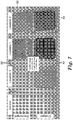
- FIG. 7 is a photograph of the indicators of Example 1 following an approximately two week evaluation period in their respective environments and with a clean control indicator included for reference.
- the first medium 80 showed a more substantial color changed than the discharged second medium 82.
- the indicator exposed to outdoor area i.e., location 1)
- a series of air quality indicators were prepared using two different media types, as shown in FIG. 8 .
- a first medium 100 was an electrostatically charged filter medium available from 3M Company of St. Paul, MN under the trade designation Filtrete 1200.
- a second medium 102 was the same Filtrete 1200 medium, except discharged by saturation in isopropyl alcohol.
- a third medium 104 consisted of an uncharged staple fiber web available from Ahlstrom, under the trade designation Model T817.
- the media 100-104 were approximately 5.08 cm x 7.62 cm (2 inch x 3 inch) in size, and were attached to a cardboard perimeter frame.
- Air quality evaluations were performed using the air quality indicator samples of Example 2 at four locations. 1) On an outdoor air inlet (thus pulling 100% outdoor air) to a building's HVAC system (located in St. Paul, MN) for a period of 13 days. Using accepted fine particle measuring equipment, the average outdoor fine particle level during the evaluation period was found to be 6 ⁇ g/m 3 . 2) On an indoor air return at a room in the building of 1) above, for an evaluation period of 13 days. This configuration exposed the indicator to 100% indoor air, which was filtered prior to entering the building through a bank of high efficiency commercial HVAC filters. The average outdoor fine particle level during the evaluation period was estimated to be 6 ⁇ g/m 3 .
- the indoor PM 2.5 level was likely lower than the outdoor PM 2.5 level as much PM 2.5 was an outdoor source, and the building HVAC inlet air is filtered at a high level.
- 3) On the upstream side of a residential HVAC filter located at a residence in St. Paul, MN, for an evaluation period of 13 days in the summer. The residential HVAC system was run continuously on low speed except for when the system called for on-demand cooling. The average outdoor fine particle level during the evaluation period was estimated to be 5 ⁇ g/m 3 . It was noted that the indoor PM 2.5 level was likely lower than the outdoor PM 2.5 level as much PM 2.5 was an outdoor source, and the residential HVAC has minimal outdoor make-up air and included a relatively high level of filtration (via a filter available from 3M Company of St.
- FIG. 9 provides photographs of the indicators of Example 2 following an approximately two week evaluation period in their respective environments, along with a clean control indicator for reference.
- Both of the building locations (i.e., locations 1) and 2)) exhibited the greatest color change, while the residential locations (i.e., locations 3) and 4)) exhibited a lesser total color change.
- the electrostatically charged medium i.e., the first medium 100
- the uncharged media i.e., the second and third media 102, 104.
- the indicator in the residential air purifier scenario i.e., location 4)
- Indicators identical to those of Example 2 were prepared and subjected to air quality evaluations at two locations in Shanghai, China. 1) On an air inlet to a building's split air conditioning system for a period of 7 days. Using accepted fine particle measuring equipment, the average fine particle level during the evaluation period was found to be 34 ⁇ g/m 3 . 2) On an HVAC indoor air return in the building of 1) above, for an evaluation period of 7 days.
- FIG. 10 provides photographs of the indicators of Example 3 following an approximately seven day evaluation period, along with a clean control indicator for reference.
- the seven days of exposure where not seven consecutive days but were staggered for purposes of maintaining a thorough visual record of the color change.
- Both of the samples exhibited a significant color change, with the HVAC location (i.e., location 2)) showed a slightly greater change in color than the split AC location.
- the electrostatically charged web i.e., the first filter medium 100
- the electrostatically charged web i.e., the first filter medium 100
- uncharged media i.e., the second and third media 102, 104
- the discharged medium i.e., the second medium 102
- the uncharged medium the third medium 104) showed minimal color change at both locations.
- the air quality indicators, systems and related methods of use provide a marked improvement over previous designs.
- the air quality indicators are inexpensive, easy to use, and provide meaningful information regarding fine particle levels to an un-trained user.
- By combining a high efficiency (e.g., highly electrostatically charged) and low efficiency (e.g., uncharged or lightly charged) media into an indicator can provide an indicator with two parallel loading surfaces that initially appear similar (or identical) but which change color at a differential rate when exposed to contaminated air.
- the indicator can thus provide information about the quality of the air in the location sampled.
Claims (6)
- Indicateur de qualité d'air (20) pour fournir une indication de niveaux élevés de particules fines dans l'air, l'indicateur (20) comprenant :un cadre (22) définissant des première (28) et deuxième fenêtres (30) ;un premier milieu de filtre à air (24) assemblé au sein de la première fenêtre (28) et incluant une bande non tissée à électret ;un deuxième milieu de filtre à air (26) assemblé au sein de la deuxième fenêtre (30) et incluant une bande non tissée non chargée ;dans lequel le premier milieu de filtre à air (24) est configuré pour avoir un taux de variation d'apparence visuelle en présence d'un flux d'air à niveau élevé de particules fines qui est supérieur à un taux de variation d'apparence visuelle en présence d'un flux d'air à niveau élevé de particules fines du deuxième milieu de filtre à air (26).
- Indicateur (20) selon la revendication 1, dans lequel les milieux de filtre à air (24, 26) sont configurés pour avoir une apparence essentiellement similaire avant exposition à un flux d'air avec un niveau élevé de particules fines.
- Indicateur (20) selon la revendication 1, dans lequel les milieux de filtre à air (24, 26) sont essentiellement identiques en taille et en forme.
- Indicateur (20) selon la revendication 1, dans lequel le cadre (22) a une longueur n'excédant pas 15,24 cm (6 pouces) et une largeur n'excédant pas 7,62 cm (3 pouces).
- Système indicateur de qualité d'air (50) pour fournir une indication de niveaux élevés de particules fines dans l'air, le système (50) comprenant :l'indicateur (20) selon la revendication 1 ; etun filtre à grosses particules définissant un côté en amont et un côté en aval ;dans lequel l'indicateur (20) est monté au côté en aval du filtre à grosses particules.
- Procédé d'indication de l'existence de niveaux élevés de particules fines dans l'air, le procédé comprenant :
la fourniture d'un indicateur (20) incluant :un cadre (22) définissant des première (28) et deuxième fenêtres (30) ;un premier milieu de filtre à air (24) assemblé au sein de la première fenêtre (28) et incluant une bande non tissée à électret ;un deuxième milieu de filtre à air (26) assemblé au sein de la deuxième fenêtre (30) et incluant une bande non tissée non chargée ;dans lequel le premier milieu de filtre à air (24) est configuré pour avoir un taux de variation d'apparence visuelle en présence d'un flux d'air à niveau élevé de particules fines qui est supérieur à un taux de variation d'apparence visuelle en présence d'un flux d'air à niveau élevé de particules fines du deuxième milieu de filtre à air (26) ;le montage de l'indicateur (20) sur une surface à flux d'air actif (66) d'une source de flux d'air actif ; le fonctionnement de la source de flux d'air actif pour diriger le flux d'air à travers les premier (24) et deuxième milieux de filtre à air (26) ; etla comparaison visuelle d'une apparence du premier milieu de filtre à air (24) avec une apparence du deuxième milieu de filtre à air (26) à la suite de l'étape de fonctionnement de la source de flux d'air actif.
Applications Claiming Priority (2)
| Application Number | Priority Date | Filing Date | Title |
|---|---|---|---|
| US201361917165P | 2013-12-17 | 2013-12-17 | |
| PCT/US2014/068266 WO2015094652A1 (fr) | 2013-12-17 | 2014-12-03 | Indicateur de la qualité de l'air |
Publications (3)
| Publication Number | Publication Date |
|---|---|
| EP3083006A1 EP3083006A1 (fr) | 2016-10-26 |
| EP3083006A4 EP3083006A4 (fr) | 2017-08-23 |
| EP3083006B1 true EP3083006B1 (fr) | 2019-01-30 |
Family
ID=53403500
Family Applications (1)
| Application Number | Title | Priority Date | Filing Date |
|---|---|---|---|
| EP14872182.2A Not-in-force EP3083006B1 (fr) | 2013-12-17 | 2014-12-03 | Indicateur de la qualité de l'air |
Country Status (9)
| Country | Link |
|---|---|
| US (1) | US9833734B2 (fr) |
| EP (1) | EP3083006B1 (fr) |
| JP (1) | JP6118952B2 (fr) |
| KR (2) | KR20170034447A (fr) |
| CN (1) | CN105828908B (fr) |
| CA (1) | CA2933340C (fr) |
| SA (1) | SA516371339B1 (fr) |
| TW (1) | TWI636820B (fr) |
| WO (1) | WO2015094652A1 (fr) |
Families Citing this family (14)
| Publication number | Priority date | Publication date | Assignee | Title |
|---|---|---|---|---|
| CA2928138A1 (fr) | 2015-11-10 | 2017-05-10 | 3M Innovative Properties Company | Indicateurs d'utilisation de filtre a air |
| US10145764B2 (en) * | 2016-06-16 | 2018-12-04 | Lincoln Global, Inc. | Continuous flow sampling apparatus having an opening and first and second slide doors for closing the opening |
| EP3493890B1 (fr) * | 2016-08-05 | 2021-09-29 | 3M Innovative Properties Company | Filtre à air avec indicateur de durée de vie de filtre passivé |
| CN106871328A (zh) * | 2016-12-23 | 2017-06-20 | 苏州安飞荣工业科技有限公司 | 一种智能空气净化系统及其控制方法 |
| CN106839265A (zh) * | 2016-12-23 | 2017-06-13 | 苏州安飞荣工业科技有限公司 | 一种智能控制空气净化系统及其控制方法 |
| GB201700695D0 (en) * | 2017-01-16 | 2017-03-01 | Secr Defence | Personal bio-aerosol sampling device |
| CN107328021A (zh) * | 2017-06-29 | 2017-11-07 | 珠海格力电器股份有限公司 | 一种机组节能控制方法、装置及设备 |
| US10767878B2 (en) | 2017-11-21 | 2020-09-08 | Emerson Climate Technologies, Inc. | Humidifier control systems and methods |
| WO2019204792A1 (fr) | 2018-04-20 | 2019-10-24 | Emerson Climate Technologies, Inc. | Commande coordonnée de dispositifs et de systèmes autonomes et de qualité d'air intérieur de bâtiment |
| WO2019204790A1 (fr) | 2018-04-20 | 2019-10-24 | Emerson Climate Technologies, Inc. | Systèmes et procédés avec seuils d'atténuation variable |
| US11226128B2 (en) | 2018-04-20 | 2022-01-18 | Emerson Climate Technologies, Inc. | Indoor air quality and occupant monitoring systems and methods |
| US11486593B2 (en) | 2018-04-20 | 2022-11-01 | Emerson Climate Technologies, Inc. | Systems and methods with variable mitigation thresholds |
| US11371726B2 (en) | 2018-04-20 | 2022-06-28 | Emerson Climate Technologies, Inc. | Particulate-matter-size-based fan control system |
| EP4094061A1 (fr) | 2020-01-21 | 2022-11-30 | Particle Measuring Systems, Inc. | Commande robotique destinéé à un traitement aseptique |
Family Cites Families (68)
| Publication number | Priority date | Publication date | Assignee | Title |
|---|---|---|---|---|
| US2753831A (en) | 1952-05-10 | 1956-07-10 | Walter B Davies | Air filter clogging warning apparatus |
| US2804839A (en) | 1954-12-14 | 1957-09-03 | William W Hallinan | Air filter alarm systems and air filter alarm units |
| US2782747A (en) | 1955-04-11 | 1957-02-26 | Donovan C Alderfer | Alarm for air conditioning system |
| US2849005A (en) | 1955-11-15 | 1958-08-26 | Brown & Williamson Tobacco | Emblematized cigarette filter tip |
| US3027865A (en) | 1959-01-06 | 1962-04-03 | Honeywell Regulator Co | Clogged filter indicator |
| US3635001A (en) | 1969-08-05 | 1972-01-18 | Nat Union Electric Corp | Filter indicator |
| US3698871A (en) | 1970-04-16 | 1972-10-17 | George Andrew Brennan | Air pollution detectors |
| GB1407125A (en) | 1973-02-22 | 1975-09-24 | Gen Motors Ltd | Pressure responsive visual warning devices |
| NL160303C (nl) | 1974-03-25 | 1979-10-15 | Verto Nv | Werkwijze voor het vervaardigen van een vezelfilter. |
| US4130487A (en) | 1976-04-05 | 1978-12-19 | Process Scientific Innovations Ltd. | Filters for liquids or gases |
| DE7809170U1 (de) | 1978-03-25 | 1978-07-27 | Fa. Carl Freudenberg, 6940 Weinheim | Filtermatte |
| US4321070A (en) | 1980-08-22 | 1982-03-23 | Bede Industries, Inc. | Whistle to signal clogged air filter |
| AU565762B2 (en) | 1983-02-04 | 1987-09-24 | Minnesota Mining And Manufacturing Company | Method and apparatus for manufacturing an electret filter medium |
| US4729371A (en) | 1983-10-11 | 1988-03-08 | Minnesota Mining And Manufacturing Company | Respirator comprised of blown bicomponent fibers |
| US4747364A (en) | 1986-08-05 | 1988-05-31 | Filter Alert Corporation | Flow rate threshold sensor |
| US4955995A (en) | 1989-07-28 | 1990-09-11 | Columbus Industries, Inc. | Range hood filter pad |
| JPH03106286A (ja) | 1989-09-20 | 1991-05-02 | Fujitsu General Ltd | 多数カメラ同時表示装置 |
| US6268496B1 (en) | 1990-10-31 | 2001-07-31 | Neurogen Corporation | Certain imidazoquinoxalines: a new class of GABA brain receptor ligands |
| US5538690A (en) | 1991-10-21 | 1996-07-23 | Greer; Garry L. | Air quality indicator system for breathing air supplies |
| JPH05137919A (ja) * | 1991-11-19 | 1993-06-01 | Japan Tobacco Inc | エアコンデイシヨナ用脱臭フイルターのホルダー及びそれを用いたフイルター装置 |
| JPH0551426U (ja) * | 1991-12-24 | 1993-07-09 | 松下電工株式会社 | 光電式浮遊微粒子濃度検知器付空気清浄器 |
| US5230800A (en) | 1992-02-20 | 1993-07-27 | Minnesota Mining And Manufacturing Company | Scrim inserted electrostatic fibrous filter web |
| WO1994011556A1 (fr) | 1992-11-18 | 1994-05-26 | Hoechst Celanese Corporation | Structure fibreuse contenant un materiau particulaire immobilise et procede de production d'une telle structure |
| US5662728A (en) | 1992-12-31 | 1997-09-02 | Hoechst Celanese Corporation | Particulate filter structure |
| EP0714463B1 (fr) | 1993-08-17 | 1999-03-10 | Minnesota Mining And Manufacturing Company | Procede de charge d'un filtre a electret |
| DE4413148A1 (de) | 1994-04-15 | 1995-04-20 | Daimler Benz Ag | Filterbelastungsanzeige |
| US5597645A (en) | 1994-08-30 | 1997-01-28 | Kimberly-Clark Corporation | Nonwoven filter media for gas |
| JPH08110564A (ja) | 1994-10-13 | 1996-04-30 | Canon Inc | ファインダ表示装置を有する光学機器 |
| US5908598A (en) | 1995-08-14 | 1999-06-01 | Minnesota Mining And Manufacturing Company | Fibrous webs having enhanced electret properties |
| US6814909B1 (en) | 1995-10-04 | 2004-11-09 | Sumitomo Chemical Company, Limited | Indicator |
| GB2311857A (en) | 1996-04-02 | 1997-10-08 | Molyneux Shlosberg Lindsay | Monitoring gas for particulates |
| US5972808A (en) | 1997-01-30 | 1999-10-26 | Aqf Technologies Llc | Fibrous structures with fine particles |
| JP3029808B2 (ja) * | 1997-03-27 | 2000-04-10 | 日本たばこ産業株式会社 | 脱臭フィルター装置 |
| US6187596B1 (en) | 1997-07-11 | 2001-02-13 | Donaldson Company, Inc. | Airborne contaminant indicator |
| US5976467A (en) | 1997-07-11 | 1999-11-02 | Donaldson Company, Inc. | Airborne contaminant indicator |
| US6432175B1 (en) | 1998-07-02 | 2002-08-13 | 3M Innovative Properties Company | Fluorinated electret |
| US6110260A (en) | 1998-07-14 | 2000-08-29 | 3M Innovative Properties Company | Filter having a change indicator |
| US20040011204A1 (en) | 2001-10-11 | 2004-01-22 | Hendrik Both | Electrostatic fibrous filter web and method of making same |
| US7887889B2 (en) | 2001-12-14 | 2011-02-15 | 3M Innovative Properties Company | Plasma fluorination treatment of porous materials |
| US6672134B2 (en) | 2002-03-26 | 2004-01-06 | Michael D. Bodnar | Indoor air quality test apparatus |
| US6916752B2 (en) | 2002-05-20 | 2005-07-12 | 3M Innovative Properties Company | Bondable, oriented, nonwoven fibrous webs and methods for making them |
| US6979361B2 (en) * | 2002-07-17 | 2005-12-27 | Gueorgui Milev Mihayiov | End of service life indicator for fluid filter |
| KR20040013679A (ko) | 2002-08-08 | 2004-02-14 | 현대산업개발 주식회사 | 실내 공기 상태 표시장치 |
| JP2004183925A (ja) | 2002-11-29 | 2004-07-02 | Daikin Ind Ltd | エアフィルタ、空気調和機および空気質解析システム |
| KR100675681B1 (ko) | 2004-03-29 | 2007-01-29 | 이노필텍(주) | 교체시기 지시 가스여과용 여재 |
| US6858297B1 (en) | 2004-04-05 | 2005-02-22 | 3M Innovative Properties Company | Aligned fiber web |
| WO2005100988A1 (fr) * | 2004-04-16 | 2005-10-27 | Ngk Insulators, Ltd. | Pièce d’essai pour analyse |
| DE102006027882B4 (de) * | 2005-09-02 | 2009-04-30 | Clean Systems Korea Inc., Seongnam | Wäscher zum Behandeln von Halbleiter-Abgas |
| US7713339B2 (en) * | 2006-05-26 | 2010-05-11 | 3M Innovative Properties Company | Filter change indicator |
| US9120043B2 (en) | 2006-05-30 | 2015-09-01 | 3M Innovative Properties Company | Filter sensor |
| US7858163B2 (en) | 2006-07-31 | 2010-12-28 | 3M Innovative Properties Company | Molded monocomponent monolayer respirator with bimodal monolayer monocomponent media |
| US7947142B2 (en) | 2006-07-31 | 2011-05-24 | 3M Innovative Properties Company | Pleated filter with monolayer monocomponent meltspun media |
| US7749303B2 (en) | 2007-08-30 | 2010-07-06 | The Boeing Company | Service life indicator for chemical filters |
| US7806952B2 (en) | 2008-08-01 | 2010-10-05 | 3M Innovative Properties Company | Apparatus, system, and method for enhancing air purification efficiency |
| JP5706875B2 (ja) | 2009-04-03 | 2015-04-22 | スリーエム イノベイティブ プロパティズ カンパニー | 帯電強化添加剤を含むエレクトレットウェブ |
| US8365723B2 (en) * | 2009-05-22 | 2013-02-05 | 3M Innovative Properties Company | Filter cartridge having cone of visibility for end-of-service-life-indicator (ESLI) |
| JP5572210B2 (ja) * | 2009-05-22 | 2014-08-13 | スリーエム イノベイティブ プロパティズ カンパニー | 多層比色センサアレイ |
| US8225782B2 (en) * | 2009-05-22 | 2012-07-24 | 3M Innovative Properties Company | Filter cartridge having location-registered view window for end-of-service-life-indicator (ESLI) |
| DE102009025183B4 (de) | 2009-06-12 | 2012-04-26 | Testo Ag | Verfahren und Vorrichtung zur Bestimmung der Staub- und Rußpartikelkonzentration |
| US8162153B2 (en) | 2009-07-02 | 2012-04-24 | 3M Innovative Properties Company | High loft spunbonded web |
| US8955515B2 (en) * | 2009-10-23 | 2015-02-17 | 3M Innovative Properties Company | Patterned chemical sensor having inert occluding layer |
| US20120037005A1 (en) * | 2010-08-13 | 2012-02-16 | General Electric Company | Filter integrity monitoring system |
| US8574343B2 (en) * | 2011-06-20 | 2013-11-05 | Honeywell International Inc. | Methods and systems for setting an air filter change threshold in an HVAC system using a blocking panel |
| CN103781956B (zh) | 2011-06-30 | 2016-09-28 | 3M创新有限公司 | 非织造驻极体纤维网及其制备方法 |
| JP5852834B2 (ja) | 2011-10-04 | 2016-02-03 | アズビル株式会社 | 微粒子検出装置の評価システム及び微粒子検出装置の評価方法 |
| IN2014CN04300A (fr) | 2011-12-12 | 2015-09-04 | 3M Innovative Properties Co | |
| JP6370366B2 (ja) | 2013-03-15 | 2018-08-08 | スリーエム イノベイティブ プロパティズ カンパニー | 層状フィルターカートリッジのための耐用期間終了指示システム |
| WO2015103593A1 (fr) | 2014-01-06 | 2015-07-09 | Wood Robert L | Indicateur colorimétrique réagissant à un écoulement d'air |
-
2014
- 2014-12-03 KR KR1020177007472A patent/KR20170034447A/ko not_active Application Discontinuation
- 2014-12-03 CA CA2933340A patent/CA2933340C/fr active Active
- 2014-12-03 US US15/105,845 patent/US9833734B2/en active Active
- 2014-12-03 KR KR1020167019035A patent/KR101837641B1/ko active IP Right Grant
- 2014-12-03 CN CN201480068806.2A patent/CN105828908B/zh active Active
- 2014-12-03 WO PCT/US2014/068266 patent/WO2015094652A1/fr active Application Filing
- 2014-12-03 EP EP14872182.2A patent/EP3083006B1/fr not_active Not-in-force
- 2014-12-03 JP JP2016540493A patent/JP6118952B2/ja active Active
- 2014-12-16 TW TW103143946A patent/TWI636820B/zh active
-
2016
- 2016-06-16 SA SA516371339A patent/SA516371339B1/ar unknown
Non-Patent Citations (1)
| Title |
|---|
| None * |
Also Published As
| Publication number | Publication date |
|---|---|
| KR20170034447A (ko) | 2017-03-28 |
| US9833734B2 (en) | 2017-12-05 |
| CA2933340A1 (fr) | 2015-06-25 |
| CN105828908B (zh) | 2017-11-03 |
| TWI636820B (zh) | 2018-10-01 |
| TW201526973A (zh) | 2015-07-16 |
| EP3083006A1 (fr) | 2016-10-26 |
| SA516371339B1 (ar) | 2019-01-29 |
| WO2015094652A1 (fr) | 2015-06-25 |
| CN105828908A (zh) | 2016-08-03 |
| JP6118952B2 (ja) | 2017-04-19 |
| KR20160088437A (ko) | 2016-07-25 |
| CA2933340C (fr) | 2022-05-31 |
| JP2017503139A (ja) | 2017-01-26 |
| EP3083006A4 (fr) | 2017-08-23 |
| KR101837641B1 (ko) | 2018-03-12 |
| US20160310884A1 (en) | 2016-10-27 |
Similar Documents
| Publication | Publication Date | Title |
|---|---|---|
| EP3083006B1 (fr) | Indicateur de la qualité de l'air | |
| US5906677A (en) | Electrostatic supercharger screen | |
| CA2334294C (fr) | Filtre a temoin de changement | |
| JP5434076B2 (ja) | 濾材およびフィルターユニット | |
| CN105228721B (zh) | 空气过滤装置 | |
| CN101511447A (zh) | 高效hvac过滤器 | |
| Van Turnhout et al. | Electret filters for high-efficiency and high-flow air cleaning | |
| EP3493890B1 (fr) | Filtre à air avec indicateur de durée de vie de filtre passivé | |
| CN104492198B (zh) | 一种寿命可测的复合颗粒物过滤器 | |
| US7052524B1 (en) | Fan mounted air purifier | |
| KR20200092212A (ko) | 창틀 설치형 공기여과장치 | |
| CN220176327U (zh) | 一种复合滤材及电子设备 | |
| KR20200120853A (ko) | 정전기 유도 시트를 갖춘 프리 필터 | |
| JPH08224414A (ja) | エアフィルタ及びこのエアフィルを備えた空気調和機 | |
| CN105617786A (zh) | 挂壁式空调用滤芯 | |
| EP1357994B1 (fr) | Utilisation d'une matiere textile a structure tridimensionnelle en tant que protection contre les pollens pour fenetres et portes | |
| CN204060454U (zh) | 防雾霾消声百叶窗 | |
| EP1337312B1 (fr) | Utilisation de structures textiles planes a fils textures servant de systemes de protection contre les pollens sur des fenetres et des portes | |
| CN115218456A (zh) | 滤网寿命检测方法、装置及空气净化装置 | |
| Mudiya | Experimental Testing and Performance Analysis of" Room Air Cleaners" | |
| Marra et al. | Combining air filtration with ultra-fine particle sensing for an enhanced energy-efficient indoor air quality optimization | |
| JPS6336853A (ja) | 空気清浄器 | |
| JPH0811526A (ja) | 集塵フィルタ | |
| IT9060322U1 (it) | Ventilconvettore per filtrazione elettronica |
Legal Events
| Date | Code | Title | Description |
|---|---|---|---|
| PUAI | Public reference made under article 153(3) epc to a published international application that has entered the european phase |
Free format text: ORIGINAL CODE: 0009012 |
|
| 17P | Request for examination filed |
Effective date: 20160608 |
|
| AK | Designated contracting states |
Kind code of ref document: A1 Designated state(s): AL AT BE BG CH CY CZ DE DK EE ES FI FR GB GR HR HU IE IS IT LI LT LU LV MC MK MT NL NO PL PT RO RS SE SI SK SM TR |
|
| AX | Request for extension of the european patent |
Extension state: BA ME |
|
| DAX | Request for extension of the european patent (deleted) | ||
| A4 | Supplementary search report drawn up and despatched |
Effective date: 20170726 |
|
| RIC1 | Information provided on ipc code assigned before grant |
Ipc: G01N 15/06 20060101ALI20170720BHEP Ipc: G01N 15/00 20060101ALN20170720BHEP Ipc: F24F 11/00 20060101ALN20170720BHEP Ipc: G01N 21/88 20060101ALI20170720BHEP Ipc: G01N 1/22 20060101AFI20170720BHEP Ipc: F24F 3/16 20060101ALI20170720BHEP Ipc: B01D 46/00 20060101ALI20170720BHEP |
|
| STAA | Information on the status of an ep patent application or granted ep patent |
Free format text: STATUS: EXAMINATION IS IN PROGRESS |
|
| 17Q | First examination report despatched |
Effective date: 20180425 |
|
| REG | Reference to a national code |
Ref country code: DE Ref legal event code: R079 Ref document number: 602014040596 Country of ref document: DE Free format text: PREVIOUS MAIN CLASS: B01D0046420000 Ipc: G01N0001220000 |
|
| GRAP | Despatch of communication of intention to grant a patent |
Free format text: ORIGINAL CODE: EPIDOSNIGR1 |
|
| STAA | Information on the status of an ep patent application or granted ep patent |
Free format text: STATUS: GRANT OF PATENT IS INTENDED |
|
| RIC1 | Information provided on ipc code assigned before grant |
Ipc: G01N 1/22 20060101AFI20180809BHEP Ipc: G01N 21/88 20060101ALI20180809BHEP Ipc: B01D 46/00 20060101ALI20180809BHEP Ipc: G01N 15/06 20060101ALI20180809BHEP Ipc: G01N 15/00 20060101ALN20180809BHEP Ipc: F24F 3/16 20060101ALI20180809BHEP Ipc: F24F 11/00 20060101ALN20180809BHEP |
|
| INTG | Intention to grant announced |
Effective date: 20180906 |
|
| GRAS | Grant fee paid |
Free format text: ORIGINAL CODE: EPIDOSNIGR3 |
|
| GRAA | (expected) grant |
Free format text: ORIGINAL CODE: 0009210 |
|
| STAA | Information on the status of an ep patent application or granted ep patent |
Free format text: STATUS: THE PATENT HAS BEEN GRANTED |
|
| AK | Designated contracting states |
Kind code of ref document: B1 Designated state(s): AL AT BE BG CH CY CZ DE DK EE ES FI FR GB GR HR HU IE IS IT LI LT LU LV MC MK MT NL NO PL PT RO RS SE SI SK SM TR |
|
| REG | Reference to a national code |
Ref country code: GB Ref legal event code: FG4D |
|
| REG | Reference to a national code |
Ref country code: CH Ref legal event code: EP |
|
| REG | Reference to a national code |
Ref country code: AT Ref legal event code: REF Ref document number: 1093678 Country of ref document: AT Kind code of ref document: T Effective date: 20190215 |
|
| REG | Reference to a national code |
Ref country code: IE Ref legal event code: FG4D |
|
| REG | Reference to a national code |
Ref country code: DE Ref legal event code: R096 Ref document number: 602014040596 Country of ref document: DE |
|
| REG | Reference to a national code |
Ref country code: LT Ref legal event code: MG4D |
|
| REG | Reference to a national code |
Ref country code: NL Ref legal event code: MP Effective date: 20190130 |
|
| PG25 | Lapsed in a contracting state [announced via postgrant information from national office to epo] |
Ref country code: LT Free format text: LAPSE BECAUSE OF FAILURE TO SUBMIT A TRANSLATION OF THE DESCRIPTION OR TO PAY THE FEE WITHIN THE PRESCRIBED TIME-LIMIT Effective date: 20190130 Ref country code: PL Free format text: LAPSE BECAUSE OF FAILURE TO SUBMIT A TRANSLATION OF THE DESCRIPTION OR TO PAY THE FEE WITHIN THE PRESCRIBED TIME-LIMIT Effective date: 20190130 Ref country code: NL Free format text: LAPSE BECAUSE OF FAILURE TO SUBMIT A TRANSLATION OF THE DESCRIPTION OR TO PAY THE FEE WITHIN THE PRESCRIBED TIME-LIMIT Effective date: 20190130 Ref country code: FI Free format text: LAPSE BECAUSE OF FAILURE TO SUBMIT A TRANSLATION OF THE DESCRIPTION OR TO PAY THE FEE WITHIN THE PRESCRIBED TIME-LIMIT Effective date: 20190130 Ref country code: ES Free format text: LAPSE BECAUSE OF FAILURE TO SUBMIT A TRANSLATION OF THE DESCRIPTION OR TO PAY THE FEE WITHIN THE PRESCRIBED TIME-LIMIT Effective date: 20190130 Ref country code: NO Free format text: LAPSE BECAUSE OF FAILURE TO SUBMIT A TRANSLATION OF THE DESCRIPTION OR TO PAY THE FEE WITHIN THE PRESCRIBED TIME-LIMIT Effective date: 20190430 Ref country code: SE Free format text: LAPSE BECAUSE OF FAILURE TO SUBMIT A TRANSLATION OF THE DESCRIPTION OR TO PAY THE FEE WITHIN THE PRESCRIBED TIME-LIMIT Effective date: 20190130 Ref country code: PT Free format text: LAPSE BECAUSE OF FAILURE TO SUBMIT A TRANSLATION OF THE DESCRIPTION OR TO PAY THE FEE WITHIN THE PRESCRIBED TIME-LIMIT Effective date: 20190530 |
|
| REG | Reference to a national code |
Ref country code: AT Ref legal event code: MK05 Ref document number: 1093678 Country of ref document: AT Kind code of ref document: T Effective date: 20190130 |
|
| PG25 | Lapsed in a contracting state [announced via postgrant information from national office to epo] |
Ref country code: GR Free format text: LAPSE BECAUSE OF FAILURE TO SUBMIT A TRANSLATION OF THE DESCRIPTION OR TO PAY THE FEE WITHIN THE PRESCRIBED TIME-LIMIT Effective date: 20190501 Ref country code: LV Free format text: LAPSE BECAUSE OF FAILURE TO SUBMIT A TRANSLATION OF THE DESCRIPTION OR TO PAY THE FEE WITHIN THE PRESCRIBED TIME-LIMIT Effective date: 20190130 Ref country code: IS Free format text: LAPSE BECAUSE OF FAILURE TO SUBMIT A TRANSLATION OF THE DESCRIPTION OR TO PAY THE FEE WITHIN THE PRESCRIBED TIME-LIMIT Effective date: 20190530 Ref country code: HR Free format text: LAPSE BECAUSE OF FAILURE TO SUBMIT A TRANSLATION OF THE DESCRIPTION OR TO PAY THE FEE WITHIN THE PRESCRIBED TIME-LIMIT Effective date: 20190130 Ref country code: RS Free format text: LAPSE BECAUSE OF FAILURE TO SUBMIT A TRANSLATION OF THE DESCRIPTION OR TO PAY THE FEE WITHIN THE PRESCRIBED TIME-LIMIT Effective date: 20190130 Ref country code: BG Free format text: LAPSE BECAUSE OF FAILURE TO SUBMIT A TRANSLATION OF THE DESCRIPTION OR TO PAY THE FEE WITHIN THE PRESCRIBED TIME-LIMIT Effective date: 20190430 |
|
| PG25 | Lapsed in a contracting state [announced via postgrant information from national office to epo] |
Ref country code: AL Free format text: LAPSE BECAUSE OF FAILURE TO SUBMIT A TRANSLATION OF THE DESCRIPTION OR TO PAY THE FEE WITHIN THE PRESCRIBED TIME-LIMIT Effective date: 20190130 Ref country code: CZ Free format text: LAPSE BECAUSE OF FAILURE TO SUBMIT A TRANSLATION OF THE DESCRIPTION OR TO PAY THE FEE WITHIN THE PRESCRIBED TIME-LIMIT Effective date: 20190130 Ref country code: RO Free format text: LAPSE BECAUSE OF FAILURE TO SUBMIT A TRANSLATION OF THE DESCRIPTION OR TO PAY THE FEE WITHIN THE PRESCRIBED TIME-LIMIT Effective date: 20190130 Ref country code: SK Free format text: LAPSE BECAUSE OF FAILURE TO SUBMIT A TRANSLATION OF THE DESCRIPTION OR TO PAY THE FEE WITHIN THE PRESCRIBED TIME-LIMIT Effective date: 20190130 Ref country code: EE Free format text: LAPSE BECAUSE OF FAILURE TO SUBMIT A TRANSLATION OF THE DESCRIPTION OR TO PAY THE FEE WITHIN THE PRESCRIBED TIME-LIMIT Effective date: 20190130 Ref country code: IT Free format text: LAPSE BECAUSE OF FAILURE TO SUBMIT A TRANSLATION OF THE DESCRIPTION OR TO PAY THE FEE WITHIN THE PRESCRIBED TIME-LIMIT Effective date: 20190130 Ref country code: DK Free format text: LAPSE BECAUSE OF FAILURE TO SUBMIT A TRANSLATION OF THE DESCRIPTION OR TO PAY THE FEE WITHIN THE PRESCRIBED TIME-LIMIT Effective date: 20190130 |
|
| REG | Reference to a national code |
Ref country code: DE Ref legal event code: R097 Ref document number: 602014040596 Country of ref document: DE |
|
| PG25 | Lapsed in a contracting state [announced via postgrant information from national office to epo] |
Ref country code: SM Free format text: LAPSE BECAUSE OF FAILURE TO SUBMIT A TRANSLATION OF THE DESCRIPTION OR TO PAY THE FEE WITHIN THE PRESCRIBED TIME-LIMIT Effective date: 20190130 |
|
| PLBE | No opposition filed within time limit |
Free format text: ORIGINAL CODE: 0009261 |
|
| STAA | Information on the status of an ep patent application or granted ep patent |
Free format text: STATUS: NO OPPOSITION FILED WITHIN TIME LIMIT |
|
| PG25 | Lapsed in a contracting state [announced via postgrant information from national office to epo] |
Ref country code: AT Free format text: LAPSE BECAUSE OF FAILURE TO SUBMIT A TRANSLATION OF THE DESCRIPTION OR TO PAY THE FEE WITHIN THE PRESCRIBED TIME-LIMIT Effective date: 20190130 |
|
| 26N | No opposition filed |
Effective date: 20191031 |
|
| PG25 | Lapsed in a contracting state [announced via postgrant information from national office to epo] |
Ref country code: SI Free format text: LAPSE BECAUSE OF FAILURE TO SUBMIT A TRANSLATION OF THE DESCRIPTION OR TO PAY THE FEE WITHIN THE PRESCRIBED TIME-LIMIT Effective date: 20190130 |
|
| PG25 | Lapsed in a contracting state [announced via postgrant information from national office to epo] |
Ref country code: TR Free format text: LAPSE BECAUSE OF FAILURE TO SUBMIT A TRANSLATION OF THE DESCRIPTION OR TO PAY THE FEE WITHIN THE PRESCRIBED TIME-LIMIT Effective date: 20190130 |
|
| REG | Reference to a national code |
Ref country code: DE Ref legal event code: R119 Ref document number: 602014040596 Country of ref document: DE |
|
| REG | Reference to a national code |
Ref country code: CH Ref legal event code: PL |
|
| REG | Reference to a national code |
Ref country code: BE Ref legal event code: MM Effective date: 20191231 |
|
| PG25 | Lapsed in a contracting state [announced via postgrant information from national office to epo] |
Ref country code: MC Free format text: LAPSE BECAUSE OF FAILURE TO SUBMIT A TRANSLATION OF THE DESCRIPTION OR TO PAY THE FEE WITHIN THE PRESCRIBED TIME-LIMIT Effective date: 20190130 |
|
| GBPC | Gb: european patent ceased through non-payment of renewal fee |
Effective date: 20191203 |
|
| PG25 | Lapsed in a contracting state [announced via postgrant information from national office to epo] |
Ref country code: LU Free format text: LAPSE BECAUSE OF NON-PAYMENT OF DUE FEES Effective date: 20191203 Ref country code: IE Free format text: LAPSE BECAUSE OF NON-PAYMENT OF DUE FEES Effective date: 20191203 Ref country code: DE Free format text: LAPSE BECAUSE OF NON-PAYMENT OF DUE FEES Effective date: 20200701 Ref country code: GB Free format text: LAPSE BECAUSE OF NON-PAYMENT OF DUE FEES Effective date: 20191203 |
|
| PG25 | Lapsed in a contracting state [announced via postgrant information from national office to epo] |
Ref country code: LI Free format text: LAPSE BECAUSE OF NON-PAYMENT OF DUE FEES Effective date: 20191231 Ref country code: CH Free format text: LAPSE BECAUSE OF NON-PAYMENT OF DUE FEES Effective date: 20191231 Ref country code: BE Free format text: LAPSE BECAUSE OF NON-PAYMENT OF DUE FEES Effective date: 20191231 |
|
| PG25 | Lapsed in a contracting state [announced via postgrant information from national office to epo] |
Ref country code: CY Free format text: LAPSE BECAUSE OF FAILURE TO SUBMIT A TRANSLATION OF THE DESCRIPTION OR TO PAY THE FEE WITHIN THE PRESCRIBED TIME-LIMIT Effective date: 20190130 |
|
| PG25 | Lapsed in a contracting state [announced via postgrant information from national office to epo] |
Ref country code: HU Free format text: LAPSE BECAUSE OF FAILURE TO SUBMIT A TRANSLATION OF THE DESCRIPTION OR TO PAY THE FEE WITHIN THE PRESCRIBED TIME-LIMIT; INVALID AB INITIO Effective date: 20141203 Ref country code: MT Free format text: LAPSE BECAUSE OF FAILURE TO SUBMIT A TRANSLATION OF THE DESCRIPTION OR TO PAY THE FEE WITHIN THE PRESCRIBED TIME-LIMIT Effective date: 20190130 Ref country code: FR Free format text: LAPSE BECAUSE OF NON-PAYMENT OF DUE FEES Effective date: 20191231 |
|
| PG25 | Lapsed in a contracting state [announced via postgrant information from national office to epo] |
Ref country code: MK Free format text: LAPSE BECAUSE OF FAILURE TO SUBMIT A TRANSLATION OF THE DESCRIPTION OR TO PAY THE FEE WITHIN THE PRESCRIBED TIME-LIMIT Effective date: 20190130 |