EP3082201A1 - Verbinder - Google Patents
Verbinder Download PDFInfo
- Publication number
- EP3082201A1 EP3082201A1 EP14870032.1A EP14870032A EP3082201A1 EP 3082201 A1 EP3082201 A1 EP 3082201A1 EP 14870032 A EP14870032 A EP 14870032A EP 3082201 A1 EP3082201 A1 EP 3082201A1
- Authority
- EP
- European Patent Office
- Prior art keywords
- inverter
- motor
- side terminal
- terminal
- housing
- Prior art date
- Legal status (The legal status is an assumption and is not a legal conclusion. Google has not performed a legal analysis and makes no representation as to the accuracy of the status listed.)
- Granted
Links
Images


Classifications
-
- H—ELECTRICITY
- H01—ELECTRIC ELEMENTS
- H01R—ELECTRICALLY-CONDUCTIVE CONNECTIONS; STRUCTURAL ASSOCIATIONS OF A PLURALITY OF MUTUALLY-INSULATED ELECTRICAL CONNECTING ELEMENTS; COUPLING DEVICES; CURRENT COLLECTORS
- H01R13/00—Details of coupling devices of the kinds covered by groups H01R12/70 or H01R24/00 - H01R33/00
- H01R13/62—Means for facilitating engagement or disengagement of coupling parts or for holding them in engagement
- H01R13/629—Additional means for facilitating engagement or disengagement of coupling parts, e.g. aligning or guiding means, levers, gas pressure electrical locking indicators, manufacturing tolerances
- H01R13/631—Additional means for facilitating engagement or disengagement of coupling parts, e.g. aligning or guiding means, levers, gas pressure electrical locking indicators, manufacturing tolerances for engagement only
- H01R13/6315—Additional means for facilitating engagement or disengagement of coupling parts, e.g. aligning or guiding means, levers, gas pressure electrical locking indicators, manufacturing tolerances for engagement only allowing relative movement between coupling parts, e.g. floating connection
-
- B—PERFORMING OPERATIONS; TRANSPORTING
- B60—VEHICLES IN GENERAL
- B60L—PROPULSION OF ELECTRICALLY-PROPELLED VEHICLES; SUPPLYING ELECTRIC POWER FOR AUXILIARY EQUIPMENT OF ELECTRICALLY-PROPELLED VEHICLES; ELECTRODYNAMIC BRAKE SYSTEMS FOR VEHICLES IN GENERAL; MAGNETIC SUSPENSION OR LEVITATION FOR VEHICLES; MONITORING OPERATING VARIABLES OF ELECTRICALLY-PROPELLED VEHICLES; ELECTRIC SAFETY DEVICES FOR ELECTRICALLY-PROPELLED VEHICLES
- B60L3/00—Electric devices on electrically-propelled vehicles for safety purposes; Monitoring operating variables, e.g. speed, deceleration or energy consumption
-
- B—PERFORMING OPERATIONS; TRANSPORTING
- B60—VEHICLES IN GENERAL
- B60L—PROPULSION OF ELECTRICALLY-PROPELLED VEHICLES; SUPPLYING ELECTRIC POWER FOR AUXILIARY EQUIPMENT OF ELECTRICALLY-PROPELLED VEHICLES; ELECTRODYNAMIC BRAKE SYSTEMS FOR VEHICLES IN GENERAL; MAGNETIC SUSPENSION OR LEVITATION FOR VEHICLES; MONITORING OPERATING VARIABLES OF ELECTRICALLY-PROPELLED VEHICLES; ELECTRIC SAFETY DEVICES FOR ELECTRICALLY-PROPELLED VEHICLES
- B60L53/00—Methods of charging batteries, specially adapted for electric vehicles; Charging stations or on-board charging equipment therefor; Exchange of energy storage elements in electric vehicles
- B60L53/10—Methods of charging batteries, specially adapted for electric vehicles; Charging stations or on-board charging equipment therefor; Exchange of energy storage elements in electric vehicles characterised by the energy transfer between the charging station and the vehicle
- B60L53/14—Conductive energy transfer
- B60L53/16—Connectors, e.g. plugs or sockets, specially adapted for charging electric vehicles
-
- H—ELECTRICITY
- H02—GENERATION; CONVERSION OR DISTRIBUTION OF ELECTRIC POWER
- H02K—DYNAMO-ELECTRIC MACHINES
- H02K5/00—Casings; Enclosures; Supports
- H02K5/04—Casings or enclosures characterised by the shape, form or construction thereof
- H02K5/22—Auxiliary parts of casings not covered by groups H02K5/06-H02K5/20, e.g. shaped to form connection boxes or terminal boxes
- H02K5/225—Terminal boxes or connection arrangements
-
- H—ELECTRICITY
- H01—ELECTRIC ELEMENTS
- H01R—ELECTRICALLY-CONDUCTIVE CONNECTIONS; STRUCTURAL ASSOCIATIONS OF A PLURALITY OF MUTUALLY-INSULATED ELECTRICAL CONNECTING ELEMENTS; COUPLING DEVICES; CURRENT COLLECTORS
- H01R12/00—Structural associations of a plurality of mutually-insulated electrical connecting elements, specially adapted for printed circuits, e.g. printed circuit boards [PCB], flat or ribbon cables, or like generally planar structures, e.g. terminal strips, terminal blocks; Coupling devices specially adapted for printed circuits, flat or ribbon cables, or like generally planar structures; Terminals specially adapted for contact with, or insertion into, printed circuits, flat or ribbon cables, or like generally planar structures
- H01R12/70—Coupling devices
- H01R12/91—Coupling devices allowing relative movement between coupling parts, e.g. floating or self aligning
-
- H—ELECTRICITY
- H01—ELECTRIC ELEMENTS
- H01R—ELECTRICALLY-CONDUCTIVE CONNECTIONS; STRUCTURAL ASSOCIATIONS OF A PLURALITY OF MUTUALLY-INSULATED ELECTRICAL CONNECTING ELEMENTS; COUPLING DEVICES; CURRENT COLLECTORS
- H01R13/00—Details of coupling devices of the kinds covered by groups H01R12/70 or H01R24/00 - H01R33/00
- H01R13/02—Contact members
- H01R13/28—Contacts for sliding cooperation with identically-shaped contact, e.g. for hermaphroditic coupling devices
-
- H—ELECTRICITY
- H01—ELECTRIC ELEMENTS
- H01R—ELECTRICALLY-CONDUCTIVE CONNECTIONS; STRUCTURAL ASSOCIATIONS OF A PLURALITY OF MUTUALLY-INSULATED ELECTRICAL CONNECTING ELEMENTS; COUPLING DEVICES; CURRENT COLLECTORS
- H01R13/00—Details of coupling devices of the kinds covered by groups H01R12/70 or H01R24/00 - H01R33/00
- H01R13/46—Bases; Cases
- H01R13/52—Dustproof, splashproof, drip-proof, waterproof, or flameproof cases
- H01R13/5202—Sealing means between parts of housing or between housing part and a wall, e.g. sealing rings
-
- H—ELECTRICITY
- H01—ELECTRIC ELEMENTS
- H01R—ELECTRICALLY-CONDUCTIVE CONNECTIONS; STRUCTURAL ASSOCIATIONS OF A PLURALITY OF MUTUALLY-INSULATED ELECTRICAL CONNECTING ELEMENTS; COUPLING DEVICES; CURRENT COLLECTORS
- H01R13/00—Details of coupling devices of the kinds covered by groups H01R12/70 or H01R24/00 - H01R33/00
- H01R13/56—Means for preventing chafing or fracture of flexible leads at outlet from coupling part
- H01R13/562—Bending-relieving
-
- H—ELECTRICITY
- H01—ELECTRIC ELEMENTS
- H01R—ELECTRICALLY-CONDUCTIVE CONNECTIONS; STRUCTURAL ASSOCIATIONS OF A PLURALITY OF MUTUALLY-INSULATED ELECTRICAL CONNECTING ELEMENTS; COUPLING DEVICES; CURRENT COLLECTORS
- H01R13/00—Details of coupling devices of the kinds covered by groups H01R12/70 or H01R24/00 - H01R33/00
- H01R13/56—Means for preventing chafing or fracture of flexible leads at outlet from coupling part
- H01R13/565—Torsion-relieving
-
- H—ELECTRICITY
- H01—ELECTRIC ELEMENTS
- H01R—ELECTRICALLY-CONDUCTIVE CONNECTIONS; STRUCTURAL ASSOCIATIONS OF A PLURALITY OF MUTUALLY-INSULATED ELECTRICAL CONNECTING ELEMENTS; COUPLING DEVICES; CURRENT COLLECTORS
- H01R13/00—Details of coupling devices of the kinds covered by groups H01R12/70 or H01R24/00 - H01R33/00
- H01R13/58—Means for relieving strain on wire connection, e.g. cord grip, for avoiding loosening of connections between wires and terminals within a coupling device terminating a cable
-
- H—ELECTRICITY
- H01—ELECTRIC ELEMENTS
- H01R—ELECTRICALLY-CONDUCTIVE CONNECTIONS; STRUCTURAL ASSOCIATIONS OF A PLURALITY OF MUTUALLY-INSULATED ELECTRICAL CONNECTING ELEMENTS; COUPLING DEVICES; CURRENT COLLECTORS
- H01R2201/00—Connectors or connections adapted for particular applications
- H01R2201/26—Connectors or connections adapted for particular applications for vehicles
-
- Y—GENERAL TAGGING OF NEW TECHNOLOGICAL DEVELOPMENTS; GENERAL TAGGING OF CROSS-SECTIONAL TECHNOLOGIES SPANNING OVER SEVERAL SECTIONS OF THE IPC; TECHNICAL SUBJECTS COVERED BY FORMER USPC CROSS-REFERENCE ART COLLECTIONS [XRACs] AND DIGESTS
- Y02—TECHNOLOGIES OR APPLICATIONS FOR MITIGATION OR ADAPTATION AGAINST CLIMATE CHANGE
- Y02T—CLIMATE CHANGE MITIGATION TECHNOLOGIES RELATED TO TRANSPORTATION
- Y02T10/00—Road transport of goods or passengers
- Y02T10/60—Other road transportation technologies with climate change mitigation effect
- Y02T10/64—Electric machine technologies in electromobility
-
- Y—GENERAL TAGGING OF NEW TECHNOLOGICAL DEVELOPMENTS; GENERAL TAGGING OF CROSS-SECTIONAL TECHNOLOGIES SPANNING OVER SEVERAL SECTIONS OF THE IPC; TECHNICAL SUBJECTS COVERED BY FORMER USPC CROSS-REFERENCE ART COLLECTIONS [XRACs] AND DIGESTS
- Y02—TECHNOLOGIES OR APPLICATIONS FOR MITIGATION OR ADAPTATION AGAINST CLIMATE CHANGE
- Y02T—CLIMATE CHANGE MITIGATION TECHNOLOGIES RELATED TO TRANSPORTATION
- Y02T10/00—Road transport of goods or passengers
- Y02T10/60—Other road transportation technologies with climate change mitigation effect
- Y02T10/70—Energy storage systems for electromobility, e.g. batteries
-
- Y—GENERAL TAGGING OF NEW TECHNOLOGICAL DEVELOPMENTS; GENERAL TAGGING OF CROSS-SECTIONAL TECHNOLOGIES SPANNING OVER SEVERAL SECTIONS OF THE IPC; TECHNICAL SUBJECTS COVERED BY FORMER USPC CROSS-REFERENCE ART COLLECTIONS [XRACs] AND DIGESTS
- Y02—TECHNOLOGIES OR APPLICATIONS FOR MITIGATION OR ADAPTATION AGAINST CLIMATE CHANGE
- Y02T—CLIMATE CHANGE MITIGATION TECHNOLOGIES RELATED TO TRANSPORTATION
- Y02T10/00—Road transport of goods or passengers
- Y02T10/60—Other road transportation technologies with climate change mitigation effect
- Y02T10/7072—Electromobility specific charging systems or methods for batteries, ultracapacitors, supercapacitors or double-layer capacitors
-
- Y—GENERAL TAGGING OF NEW TECHNOLOGICAL DEVELOPMENTS; GENERAL TAGGING OF CROSS-SECTIONAL TECHNOLOGIES SPANNING OVER SEVERAL SECTIONS OF THE IPC; TECHNICAL SUBJECTS COVERED BY FORMER USPC CROSS-REFERENCE ART COLLECTIONS [XRACs] AND DIGESTS
- Y02—TECHNOLOGIES OR APPLICATIONS FOR MITIGATION OR ADAPTATION AGAINST CLIMATE CHANGE
- Y02T—CLIMATE CHANGE MITIGATION TECHNOLOGIES RELATED TO TRANSPORTATION
- Y02T90/00—Enabling technologies or technologies with a potential or indirect contribution to GHG emissions mitigation
- Y02T90/10—Technologies relating to charging of electric vehicles
- Y02T90/14—Plug-in electric vehicles
Definitions
- the present invention relates to a connector.
- Patent literature 1 Japanese Unexamined Patent Publication No. 2011-187224
- an inverter-side terminal and a motor-side terminal are normally fitted after the inverter and the motor are once positioned relative to each other.
- relative positions of the both terminals may be displaced in each direction due to component variations and assembly variations in fitting the terminals. If such displacements occur, it is difficult to satisfactorily fit the terminals and establish connection between the terminals.
- the present invention was created in view of the above problem and aims to facilitate connection between an inverter and a motor by effectively absorbing displacements of relative positions of both terminals in each direction in fitting the terminals.
- a connector of the present invention is a connector for connecting an inverter and a motor and includes an inverter-side terminal block provided on the inverter side, a motor-side terminal block provided on the motor side, a first housing supported on a first supporting surface provided in the inverter-side terminal block in a floating manner, a second housing supported on a second supporting surface provided in the inverter-side terminal block in a floating manner, a first terminal held in the first housing and to be mated with an inverter-side terminal for supplying alternating-current power from the inverter in a direction orthogonal to the first supporting surface, a second terminal held in the second housing and to be mated with a motor-side terminal provided in the motor-side terminal block in a direction orthogonal to the second supporting surface, and a flexible conductive wire having one end part connected to the first terminal and the other end part connected to the second terminal and arranged slidably in each of directions along the first supporting surface and directions along the second supporting surface.
- the first terminal is mated with the inverter-side terminal in the direction orthogonal to the first supporting surface, displacements can be absorbed by changing a degree of mating connection when relative positions of the first terminal and the inverter-side terminal are displaced in the direction orthogonal to the first supporting surface in fitting the first terminal and the inverter-side terminal.
- the first housing is supported on the first supporting surface in a floating manner and the conductive wire connected to the first terminal held in the first housing is slidable in the directions along the first supporting surface.
- the first housing and the first terminal slide in the direction along the first supporting surface together with the conductive wire, thereby being able to absorb the displacements.
- the second terminal is mated with the motor-side terminal in the direction orthogonal to the second supporting surface, displacements can be absorbed by changing a degree of mating connection when relative positions of the second terminal and the motor-side terminal are displaced in the direction orthogonal to the second supporting surface in fitting the second terminal and the motor-side terminal.
- the second housing is supported on the second supporting surface in a floating manner and the conductive wire connected to the second terminal held in the second housing is slidable in the directions along the second supporting surface.
- the conductive wire may be arranged in the inverter-side terminal block, and the first and second supporting surfaces may be provided in parallel in the inverter-side terminal block.
- the conductive wire can be easily arranged in the inverter-side terminal block.
- connectors 1 are illustrated which electrically connect an unillustrated inverter and an unillustrated motor, for example, in a hybrid vehicle or an electric vehicle.
- an X axis, a Y axis and a Z axis orthogonal to each other are shown in a part of each drawing and each axial direction is drawn to be a direction shown in each drawing. Out of these, the Z-axis direction coincides with a vertical direction with an upper side on the planes of FIGS. 2 to 8 as an upper side.
- the inverter is accommodated into an inverter case 10 and the motor is accommodated into a motor case 20 with an upper side as an inverter side and a lower side as a motor side.
- the motor is accommodated into a motor case 20 with an upper side as an inverter side and a lower side as a motor side. Note that, in each drawing, only a lower part of the inverter case 10 for covering a lower side of the inverter is shown and only an upper part of the motor case 20 for covering an upper side of the motor is shown.
- each connector 1 of this embodiment is arranged side by side along the Y-axis direction between the inverter side and the motor side to connect the inverter and the motor as shown in FIGS. 1 and 2 .
- each connector 1 is arranged between an inverter-side terminal 82 and a motor-side terminal 92 and serves as an intermediate terminal for electrically connecting the both terminals.
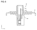
- the inverter-side terminal 82 is a male terminal extending from the inverter side electrically connected to the inverter and supplies alternating-current power supplied from the inverter side to the motor. As shown in FIGS. 3 and 7 , the inverter-side terminal 82 is held in an inverter-side housing 80 with a lower side as a connection side. The inverter-side housing 80 is open downward and arranged above the lower part of the inverter case 10.
- a part of the lower part of the inverter case 10 is provided with a rib-like inverter-side rib 12 projecting downward and an inverter-side opening 14 surrounded by this inverter-side rib 12.
- a part of the upper part of the motor case 20 is provided with a rib-like motor-side rib 22 projecting upward and a motor-side opening 24 surrounded by this motor-side rib 22.
- the connector 1 includes an inverter-side terminal block 30, a motor-side terminal block 40, a first housing 50, a first terminal 52 held in the first housing 50, a second housing 60, a second terminal 62 held in the second housing 60 and a braided wire (example of a conductive wire) 70 for connecting the first and second terminals 52, 62.
- the inverter-side terminal block 30 is provided on the inverter side (upper side) and the motor-side terminal block 40 is provided in the motor side (lower side).
- the inverter-side terminal block 30 is a member having a smaller size in a plan view than the lower part of the inverter case 10.
- the inverter-side terminal block 30 is provided with a first mounting portion 32 and a second mounting portion 34. Out of these, the first mounting portion 32 overlaps with the inverter-side housing 80 in the vertical direction with the inverter-side terminal block 30 located on the lower side, and the second'mounting portion 34 overlaps with a motor-side housing 90 to be described later in the vertical direction with the inverter-side terminal block 30 located on the upper side.
- the first mounting portion 32 is in the form of a short tube open upward and a lower opening edge surface serves as a first supporting surface 32A parallel to an X-Y plane.
- the second mounting portion 23 is in the form of a short tube open downward, an upper opening edge protrudes inwardly and this protruding surface serves as a second supporting surface 34A parallel to the X-Y plane.
- the first and second supporting surfaces 32A, 32A are provided in parallel to each other.
- the first housing 50 is substantially in the form of a tube whose axial direction is aligned with the vertical direction.
- a first protruding portion 51 protruding outwardly in parallel to the X-Y plane is provided on the outer peripheral surface of the first housing 50 near a lower opening.
- the first terminal 52 On an upper opening side in the first housing 50, the first terminal 52, which is a female terminal, is held by a locking lance 54 extending from the inner wall of the first housing 50 with a connection port thereof facing upward. A part of the first terminal 52 on a side opposite to the connection port extends up to the vicinity of the lower opening along the inner wall of the first housing 50 and serves as a first connecting portion 52A to be connected to the braided wire 70 to be described later.
- the first housing 50 is mounted in the first mounting portion 32 with the first protruding portion 51 thereof placed on the first supporting surface 32A of the first mounting portion 32, thereby being supported on the first supporting surface 32A in a floating manner.
- the first housing 50 is slidable in directions parallel to the first supporting surface 32A, i.e. along the X-Y plane by being supported on the first supporting surface 32A in a floating manner.
- the second housing 60 is configured substantially identically to the first housing 50 and mounted in the second mounting portion 34 in a posture vertically inverted from that of the first housing 50.
- the second housing 60 is substantially in the form of a tube whose axial direction is aligned with the vertical direction and a second protruding portion 61 protruding outwardly in parallel to the X-Y plane is provided on the outer peripheral surface of the second housing 60 near an upper opening.
- the second terminal 62 On a lower opening side in the second housing 60, the second terminal 62, which is a female terminal, is held by a locking lance 64 extending from the inner wall of the second housing 60 with a connection port thereof facing downward. A part of the second terminal 62 on a side opposite to the connection port extends up to the vicinity of the upper opening along the inner wall of the second housing 60 and serves as a second connecting portion 62A to be connected to the braided wire 70 to be described later.
- the second protruding portion 61 of the second housing 60 is placed on the second supporting surface 34A of the second mounting portion 34. Further, an annular retainer member 72 is mounted from the lower opening side of the second mounting portion 34 while the second housing 60 is inserted therein. In this way, the second housing 60 is mounted in the second mounting portion 34 with the second protruding portion 61 thereof sandwiched between the second supporting surface 34A and the retainer member 72, thereby being supported on the second supporting surface 34A in a floating manner.
- the second housing 60 is slidable in directions parallel to the second supporting surface 34A, i.e. along the X-Y plane by being supported on the second supporting surface 34A in a floating manner.
- the braided wire 70 is a flexible conductive member and laid slidably in X-Y plane directions in the inverter-side terminal block 30. In other words, the braided wire 70 is arranged slidably in directions along the first supporting surface 32A and directions along the second supporting surface 34A in the inverter-side terminal block 30.
- one end part 70A of the braided wire 70 is electrically connected to the first connecting portion 52A of the first terminal 50 held in the first housing 50, and another end part 70B thereof is electrically connected to the second connecting portion 62A of the second terminal 62 held in the second housing 60.
- the first and second terminals 52, 62 are electrically connected via the braided wire 70 in the inverter-side terminal block 30.
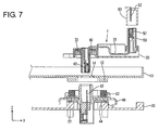
- the motor-side terminal block 40 is placed on the upper part of the motor case 20. As shown in FIG. 7 , the motor-side terminal block 40 is provided with a substantially plate-like main body portion 42 and a projecting portion 44 vertically projecting from a part of the main body portion 42.
- the motor-side terminal block 40 is fixed to the motor case 20 by being fastened to the motor case 20 by bolts B with a plate surface of the main body portion 42 placed on the motor-side rib 22 of the motor case 20 and a lower part of the projecting portion 44 inserted in the motor-side opening 24.
- the motor-side housing 90 open upward is provided on an upper part of the projecting portion 44 in the motor-side terminal block 40.
- a motor-side terminal 92 which is a male terminal, is held in the motor-side housing 90 with an upper side as a connection side.
- the motor-side terminal 92 extends up to a lower part of the motor-side projecting portion 44, is electrically connected to the motor and supplies alternating-current power converted by the inverter to the motor side.
- the connector 1 of this embodiment is configured as described above. Next, its connecting procedure is described.
- the main body portion 42 of the motor-side terminal block 40 is placed on the motor-side rib 22 of the motor case 20 via a first seal member S1 and the lower part of the projecting portion 44 is inserted into the motor-side opening 24 of the motor case 20 as shown in FIG. 7 , whereby the motor-side terminal block 40 is assembled with the motor case 20 and the both are fixed.
- the first seal member S1 is arranged between the main body portion 42 of the motor-side terminal block 40 and the motor-side rib 22 in assembling the motor-side terminal block 40 with the motor-side 20 as shown in FIG. 7 , thereby sealing between the main body portion 42 and the motor-side rib 22. This can prevent or suppress the intrusion of water and the like into between the motor-side main body portion 42 and the motor-side rib 22 (into the motor case 20).
- the first housing 50 is fitted into the inverter-side housing 80 from above with the inverter-side terminal block 30 held in a state where the first and second housings 50, 60 are mounted in advance.
- the inverter-side terminal 82 and the first terminal 52 are mated in the vertical direction and electrically connected.
- the lower surface of the inverter-side terminal block 30 is placed on the inner wall of the lower part of the inverter case 10 and the lower part of the second housing 60 is inserted into the inverter-side opening 14 of the inverter case 10 as shown in FIG. 8 , whereby the connector 1 is assembled with the inverter case 10 and the both are fixed.
- the lower opening edge of the second mounting portion 34 is matched with the lower surface of the inverter-side terminal block 30 in the vertical direction.
- the second mounting portion 34 does not interfere with the inverter case 10 in assembling the connector 1 with the inverter case 10.
- the inverter case 10 and the motor case 20 are positioned relative to each other in the X-Y plane directions.
- an unillustrated knock pin is provided on either one of the inverter case 10 and the motor case 20 and an unillustrated bracket is provided on the other.
- the second housing 60 is fitted into the motor-side housing 90 from below after the inverter case 10 and the motor case 20 are positioned with respect to the inverter-side terminal block 30 assembled with the inverter case 10.
- the second terminal 62 and the motor-side terminal 92 are mated in the vertical direction and electrically connected.
- a second seal member S2 is arranged between the inverter-side rib 12 and the main body portion 42 of the motor-side terminal block 40 in connecting the second terminal 62 and the motor-side terminal 92 as shown in FIG. 3 , thereby sealing between the inverter-side rib 12 and the main body portion 42. This can prevent or suppress the intrusion of water and the like into between the inverter case 10 and the motor-side main body portion 42 (connecting part of the second terminal 62 and the motor-side terminal 92).
- the inverter-side terminal 82 and the motor-side terminal 92 are electrically connected via the connector 1 and the alternating-current power converted by the inverter is supplied to the motor. Note that since a downward acting force is applied to the motor-side terminal block 40 by the own weight of the inverter-side terminal block 30 with the second terminal 62 and the motor-side terminal 92 connected, the second terminal 62 and the motor-side terminal 92 are unlikely to be separated in the vertical direction.
- relative positions of the inverter-side terminal 82 and the first terminal 52 may be displaced in each of the X-axis direction, the Y-axis direction and the Z-axis direction due to component variations and assembly variations in fitting the both terminals 82, 52 in the above connecting procedure.
- the inverter-side terminal 82 and the first terminal 52 are mated in the direction orthogonal to the first supporting surface 32A, i.e. in the Z-axis direction in this embodiment, displacements in the Z-axis direction can be absorbed by changing a degree of mating connection.
- first housing 50 having the first terminal 52 held inside is supported on the first supporting surface 32A in a floating manner and the braided wire 70 connected to the first terminal 52 is slidable in the directions along the first supporting surface 32A, i.e. in the X-Y plane directions, displacements in the X-axis direction and the Y-axis direction can be absorbed by sliding movements of the first housing and the first terminal together with the braided wire 70.
- relative positions of the motor-side terminal 92 and the second terminal 62 may be displaced in each of the X-axis direction, the Y-axis direction and the Z-axis direction due to component variations and assembly variations in fitting the both terminals 92, 62 in the above connecting procedure.
- the motor-side terminal 92 and the second terminal 62 are mated in the direction orthogonal to the second supporting surface 34A, i.e. in the Z-axis direction in this embodiment, displacements in the Z-axis direction can be absorbed by changing a degree of mating connection.
- the second housing 60 having the second terminal 62 held inside is supported on the second supporting surface 34A in a floating manner and the braided wire 70 connected to the second terminal 62 is slidable in the directions along the second supporting surface 34A, i.e. in the X-Y plane directions, displacements in the X-axis direction and the Y-axis direction can be absorbed by sliding movements of the second housing 60 and the second terminal 62 together with the braided wire 70.
- the braided wire 70 is arranged in the inverter-side terminal block 30 and the first and second supporting surfaces 32A, 34A are provided in parallel in the inverter-side terminal block 30.
- the directions along the first supporting surface 32A and those along the second supporting surface 34A are the same directions.
- the braided wire 70 has only to be arranged slidably in one plane direction (X-Y plane direction) and the braided wire 70 can be easily arranged in the inverter terminal 30.
Landscapes
- Engineering & Computer Science (AREA)
- Power Engineering (AREA)
- Transportation (AREA)
- Mechanical Engineering (AREA)
- Life Sciences & Earth Sciences (AREA)
- Sustainable Development (AREA)
- Sustainable Energy (AREA)
- Details Of Connecting Devices For Male And Female Coupling (AREA)
- Motor Or Generator Frames (AREA)
- Connector Housings Or Holding Contact Members (AREA)
- Inverter Devices (AREA)
Applications Claiming Priority (2)
| Application Number | Priority Date | Filing Date | Title |
|---|---|---|---|
| JP2013257780A JP5967063B2 (ja) | 2013-12-13 | 2013-12-13 | コネクタ |
| PCT/JP2014/081532 WO2015087717A1 (ja) | 2013-12-13 | 2014-11-28 | コネクタ |
Publications (3)
| Publication Number | Publication Date |
|---|---|
| EP3082201A1 true EP3082201A1 (de) | 2016-10-19 |
| EP3082201A4 EP3082201A4 (de) | 2016-11-30 |
| EP3082201B1 EP3082201B1 (de) | 2019-11-27 |
Family
ID=53371028
Family Applications (1)
| Application Number | Title | Priority Date | Filing Date |
|---|---|---|---|
| EP14870032.1A Not-in-force EP3082201B1 (de) | 2013-12-13 | 2014-11-28 | Verbinder |
Country Status (5)
| Country | Link |
|---|---|
| US (1) | US9698528B2 (de) |
| EP (1) | EP3082201B1 (de) |
| JP (1) | JP5967063B2 (de) |
| CN (1) | CN105814755B (de) |
| WO (1) | WO2015087717A1 (de) |
Cited By (3)
| Publication number | Priority date | Publication date | Assignee | Title |
|---|---|---|---|---|
| WO2019206933A1 (de) * | 2018-04-24 | 2019-10-31 | Phoenix Contact Gmbh & Co. Kg | Elektrischer verbinder |
| EP3633801A4 (de) * | 2017-05-30 | 2021-03-17 | Iriso Electronics Co., Ltd. | Verbinder |
| DE102020200584A1 (de) | 2020-01-20 | 2021-07-22 | Continental Teves Ag & Co. Ohg | Stecksystem zur elektrischen Verbindung von elektronischen Baugruppen und Druckbereitstellungseinrichtung mit einem Stecksystem |
Families Citing this family (10)
| Publication number | Priority date | Publication date | Assignee | Title |
|---|---|---|---|---|
| JP2018014166A (ja) * | 2016-07-19 | 2018-01-25 | 住友電装株式会社 | コネクタ |
| CN106299781B (zh) * | 2016-08-10 | 2018-12-28 | 深圳市深台帏翔电子有限公司 | 连接器 |
| DE102017207215A1 (de) * | 2017-04-28 | 2018-10-31 | Zf Friedrichshafen Ag | Anschlusseinrichtung |
| JP6527909B2 (ja) * | 2017-06-02 | 2019-06-05 | 矢崎総業株式会社 | コネクタ設置構造及び端子台 |
| JP6848722B2 (ja) * | 2017-06-27 | 2021-03-24 | 住友電装株式会社 | コネクタ及びコネクタの取付構造 |
| JP6822922B2 (ja) | 2017-08-14 | 2021-01-27 | トヨタ自動車株式会社 | 電子機器の車載構造 |
| CN114830459B (zh) * | 2019-12-18 | 2023-12-22 | 丰田自动车株式会社 | 电线侧连接器 |
| CN113745905B (zh) * | 2020-05-29 | 2024-03-29 | 庆虹电子(苏州)有限公司 | 连接器装置及连接器浮动模块 |
| CN114336117B (zh) * | 2020-09-30 | 2024-05-31 | 台达电子工业股份有限公司 | 转接连接器 |
| JP7563269B2 (ja) * | 2021-03-26 | 2024-10-08 | マツダ株式会社 | 電動車両の下部構造 |
Family Cites Families (10)
| Publication number | Priority date | Publication date | Assignee | Title |
|---|---|---|---|---|
| JP3984579B2 (ja) * | 2003-09-16 | 2007-10-03 | 株式会社オートネットワーク技術研究所 | インバータ用コネクタ装置 |
| FR2897206B1 (fr) * | 2006-02-03 | 2008-03-21 | Mge Ups Systems Soc Par Action | Dispositif de branchement en parallele d'une pluralite d'appareils d'alimentation electrique |
| JP4665848B2 (ja) | 2006-03-15 | 2011-04-06 | 日立電線株式会社 | コネクタ構造 |
| JP4840671B2 (ja) * | 2008-10-29 | 2011-12-21 | アイシン・エィ・ダブリュ株式会社 | 電気的接続構造 |
| JP5399804B2 (ja) * | 2009-08-03 | 2014-01-29 | 矢崎総業株式会社 | コネクタ |
| DE102009029545A1 (de) * | 2009-09-17 | 2011-03-31 | Robert Bosch Gmbh | Steckverbindung |
| WO2011055806A1 (ja) * | 2009-11-06 | 2011-05-12 | 矢崎総業株式会社 | モータケースに設置されたインバータ端子台 |
| JP5721332B2 (ja) * | 2010-03-05 | 2015-05-20 | 矢崎総業株式会社 | モータケースに設置されたインバータ端子台 |
| JP5714294B2 (ja) | 2010-10-25 | 2015-05-07 | 矢崎総業株式会社 | 機器接続用コネクタ構造 |
| JP5668983B2 (ja) * | 2011-04-05 | 2015-02-12 | 株式会社オートネットワーク技術研究所 | コネクタ |
-
2013
- 2013-12-13 JP JP2013257780A patent/JP5967063B2/ja not_active Expired - Fee Related
-
2014
- 2014-11-28 EP EP14870032.1A patent/EP3082201B1/de not_active Not-in-force
- 2014-11-28 US US15/038,481 patent/US9698528B2/en active Active
- 2014-11-28 CN CN201480065911.0A patent/CN105814755B/zh not_active Expired - Fee Related
- 2014-11-28 WO PCT/JP2014/081532 patent/WO2015087717A1/ja active Application Filing
Cited By (4)
| Publication number | Priority date | Publication date | Assignee | Title |
|---|---|---|---|---|
| EP3633801A4 (de) * | 2017-05-30 | 2021-03-17 | Iriso Electronics Co., Ltd. | Verbinder |
| WO2019206933A1 (de) * | 2018-04-24 | 2019-10-31 | Phoenix Contact Gmbh & Co. Kg | Elektrischer verbinder |
| BE1026231B1 (de) * | 2018-04-24 | 2019-11-25 | Phoenix Contact Gmbh & Co | Elektrischer verbinder |
| DE102020200584A1 (de) | 2020-01-20 | 2021-07-22 | Continental Teves Ag & Co. Ohg | Stecksystem zur elektrischen Verbindung von elektronischen Baugruppen und Druckbereitstellungseinrichtung mit einem Stecksystem |
Also Published As
| Publication number | Publication date |
|---|---|
| JP5967063B2 (ja) | 2016-08-10 |
| CN105814755B (zh) | 2018-02-13 |
| EP3082201A4 (de) | 2016-11-30 |
| JP2015115251A (ja) | 2015-06-22 |
| CN105814755A (zh) | 2016-07-27 |
| US20160301160A1 (en) | 2016-10-13 |
| WO2015087717A1 (ja) | 2015-06-18 |
| US9698528B2 (en) | 2017-07-04 |
| EP3082201B1 (de) | 2019-11-27 |
Similar Documents
| Publication | Publication Date | Title |
|---|---|---|
| EP3082201B1 (de) | Verbinder | |
| EP2456018B1 (de) | Wasserdichte struktur | |
| US10211564B2 (en) | Connector-mounting structure and terminal stage | |
| US9728901B2 (en) | Connector structure | |
| CN105794048B (zh) | 具有密封结构的电连接 | |
| US9318826B2 (en) | Connector structure | |
| CN103579870A (zh) | 连接器 | |
| US9509075B2 (en) | Connector connection structure | |
| CN112217017B (zh) | 连接器 | |
| EP3089278B1 (de) | Schwimmende steckeranordnung | |
| EP2866305A1 (de) | Steckverbinder | |
| US20150244104A1 (en) | Door connector for vehicle | |
| US10096925B2 (en) | Connector | |
| CN108123252A (zh) | 连接器 | |
| JP6140473B2 (ja) | シールドコネクタ及びシールドコネクタ接続構造 | |
| JP6209997B2 (ja) | 車載電気機器 | |
| JP6052155B2 (ja) | コネクタ | |
| US10122107B2 (en) | Connection device having a resin member between a relay terminal and a conductive terminal | |
| CN116848745A (zh) | 第1线束以及复合线束 |
Legal Events
| Date | Code | Title | Description |
|---|---|---|---|
| PUAI | Public reference made under article 153(3) epc to a published international application that has entered the european phase |
Free format text: ORIGINAL CODE: 0009012 |
|
| 17P | Request for examination filed |
Effective date: 20160225 |
|
| AK | Designated contracting states |
Kind code of ref document: A1 Designated state(s): AL AT BE BG CH CY CZ DE DK EE ES FI FR GB GR HR HU IE IS IT LI LT LU LV MC MK MT NL NO PL PT RO RS SE SI SK SM TR |
|
| AX | Request for extension of the european patent |
Extension state: BA ME |
|
| A4 | Supplementary search report drawn up and despatched |
Effective date: 20161027 |
|
| RIC1 | Information provided on ipc code assigned before grant |
Ipc: B60L 3/00 20060101ALI20161021BHEP Ipc: H01R 13/631 20060101ALI20161021BHEP Ipc: H02K 5/22 20060101ALI20161021BHEP Ipc: H01R 31/06 20060101AFI20161021BHEP |
|
| DAX | Request for extension of the european patent (deleted) | ||
| STAA | Information on the status of an ep patent application or granted ep patent |
Free format text: STATUS: EXAMINATION IS IN PROGRESS |
|
| 17Q | First examination report despatched |
Effective date: 20180626 |
|
| GRAP | Despatch of communication of intention to grant a patent |
Free format text: ORIGINAL CODE: EPIDOSNIGR1 |
|
| STAA | Information on the status of an ep patent application or granted ep patent |
Free format text: STATUS: GRANT OF PATENT IS INTENDED |
|
| RIC1 | Information provided on ipc code assigned before grant |
Ipc: H01R 13/28 20060101ALN20190613BHEP Ipc: H01R 12/91 20110101ALN20190613BHEP Ipc: B60L 53/16 20190101ALI20190613BHEP Ipc: H01R 13/56 20060101ALN20190613BHEP Ipc: H01R 13/52 20060101ALN20190613BHEP Ipc: H01R 13/58 20060101ALN20190613BHEP Ipc: H01R 31/06 20060101AFI20190613BHEP Ipc: H02K 5/22 20060101ALI20190613BHEP Ipc: H01R 13/631 20060101ALI20190613BHEP |
|
| RIC1 | Information provided on ipc code assigned before grant |
Ipc: H01R 13/28 20060101ALN20190617BHEP Ipc: H01R 13/52 20060101ALN20190617BHEP Ipc: H01R 13/58 20060101ALN20190617BHEP Ipc: H02K 5/22 20060101ALI20190617BHEP Ipc: H01R 31/06 20060101AFI20190617BHEP Ipc: H01R 13/631 20060101ALI20190617BHEP Ipc: B60L 53/16 20190101ALI20190617BHEP Ipc: H01R 12/91 20110101ALN20190617BHEP Ipc: H01R 13/56 20060101ALN20190617BHEP |
|
| INTG | Intention to grant announced |
Effective date: 20190708 |
|
| GRAS | Grant fee paid |
Free format text: ORIGINAL CODE: EPIDOSNIGR3 |
|
| GRAA | (expected) grant |
Free format text: ORIGINAL CODE: 0009210 |
|
| STAA | Information on the status of an ep patent application or granted ep patent |
Free format text: STATUS: THE PATENT HAS BEEN GRANTED |
|
| AK | Designated contracting states |
Kind code of ref document: B1 Designated state(s): AL AT BE BG CH CY CZ DE DK EE ES FI FR GB GR HR HU IE IS IT LI LT LU LV MC MK MT NL NO PL PT RO RS SE SI SK SM TR |
|
| REG | Reference to a national code |
Ref country code: GB Ref legal event code: FG4D |
|
| REG | Reference to a national code |
Ref country code: CH Ref legal event code: EP |
|
| REG | Reference to a national code |
Ref country code: DE Ref legal event code: R096 Ref document number: 602014057640 Country of ref document: DE |
|
| REG | Reference to a national code |
Ref country code: AT Ref legal event code: REF Ref document number: 1207783 Country of ref document: AT Kind code of ref document: T Effective date: 20191215 |
|
| REG | Reference to a national code |
Ref country code: IE Ref legal event code: FG4D |
|
| REG | Reference to a national code |
Ref country code: NL Ref legal event code: MP Effective date: 20191127 |
|
| REG | Reference to a national code |
Ref country code: LT Ref legal event code: MG4D |
|
| PG25 | Lapsed in a contracting state [announced via postgrant information from national office to epo] |
Ref country code: GR Free format text: LAPSE BECAUSE OF FAILURE TO SUBMIT A TRANSLATION OF THE DESCRIPTION OR TO PAY THE FEE WITHIN THE PRESCRIBED TIME-LIMIT Effective date: 20200228 Ref country code: LT Free format text: LAPSE BECAUSE OF FAILURE TO SUBMIT A TRANSLATION OF THE DESCRIPTION OR TO PAY THE FEE WITHIN THE PRESCRIBED TIME-LIMIT Effective date: 20191127 Ref country code: FI Free format text: LAPSE BECAUSE OF FAILURE TO SUBMIT A TRANSLATION OF THE DESCRIPTION OR TO PAY THE FEE WITHIN THE PRESCRIBED TIME-LIMIT Effective date: 20191127 Ref country code: BG Free format text: LAPSE BECAUSE OF FAILURE TO SUBMIT A TRANSLATION OF THE DESCRIPTION OR TO PAY THE FEE WITHIN THE PRESCRIBED TIME-LIMIT Effective date: 20200227 Ref country code: NL Free format text: LAPSE BECAUSE OF FAILURE TO SUBMIT A TRANSLATION OF THE DESCRIPTION OR TO PAY THE FEE WITHIN THE PRESCRIBED TIME-LIMIT Effective date: 20191127 Ref country code: SE Free format text: LAPSE BECAUSE OF FAILURE TO SUBMIT A TRANSLATION OF THE DESCRIPTION OR TO PAY THE FEE WITHIN THE PRESCRIBED TIME-LIMIT Effective date: 20191127 Ref country code: LV Free format text: LAPSE BECAUSE OF FAILURE TO SUBMIT A TRANSLATION OF THE DESCRIPTION OR TO PAY THE FEE WITHIN THE PRESCRIBED TIME-LIMIT Effective date: 20191127 Ref country code: NO Free format text: LAPSE BECAUSE OF FAILURE TO SUBMIT A TRANSLATION OF THE DESCRIPTION OR TO PAY THE FEE WITHIN THE PRESCRIBED TIME-LIMIT Effective date: 20200227 |
|
| PG25 | Lapsed in a contracting state [announced via postgrant information from national office to epo] |
Ref country code: IS Free format text: LAPSE BECAUSE OF FAILURE TO SUBMIT A TRANSLATION OF THE DESCRIPTION OR TO PAY THE FEE WITHIN THE PRESCRIBED TIME-LIMIT Effective date: 20200327 Ref country code: HR Free format text: LAPSE BECAUSE OF FAILURE TO SUBMIT A TRANSLATION OF THE DESCRIPTION OR TO PAY THE FEE WITHIN THE PRESCRIBED TIME-LIMIT Effective date: 20191127 Ref country code: RS Free format text: LAPSE BECAUSE OF FAILURE TO SUBMIT A TRANSLATION OF THE DESCRIPTION OR TO PAY THE FEE WITHIN THE PRESCRIBED TIME-LIMIT Effective date: 20191127 |
|
| PG25 | Lapsed in a contracting state [announced via postgrant information from national office to epo] |
Ref country code: AL Free format text: LAPSE BECAUSE OF FAILURE TO SUBMIT A TRANSLATION OF THE DESCRIPTION OR TO PAY THE FEE WITHIN THE PRESCRIBED TIME-LIMIT Effective date: 20191127 |
|
| REG | Reference to a national code |
Ref country code: CH Ref legal event code: PL |
|
| PG25 | Lapsed in a contracting state [announced via postgrant information from national office to epo] |
Ref country code: ES Free format text: LAPSE BECAUSE OF FAILURE TO SUBMIT A TRANSLATION OF THE DESCRIPTION OR TO PAY THE FEE WITHIN THE PRESCRIBED TIME-LIMIT Effective date: 20191127 Ref country code: LU Free format text: LAPSE BECAUSE OF NON-PAYMENT OF DUE FEES Effective date: 20191128 Ref country code: CH Free format text: LAPSE BECAUSE OF NON-PAYMENT OF DUE FEES Effective date: 20191130 Ref country code: LI Free format text: LAPSE BECAUSE OF NON-PAYMENT OF DUE FEES Effective date: 20191130 Ref country code: CZ Free format text: LAPSE BECAUSE OF FAILURE TO SUBMIT A TRANSLATION OF THE DESCRIPTION OR TO PAY THE FEE WITHIN THE PRESCRIBED TIME-LIMIT Effective date: 20191127 Ref country code: RO Free format text: LAPSE BECAUSE OF FAILURE TO SUBMIT A TRANSLATION OF THE DESCRIPTION OR TO PAY THE FEE WITHIN THE PRESCRIBED TIME-LIMIT Effective date: 20191127 Ref country code: EE Free format text: LAPSE BECAUSE OF FAILURE TO SUBMIT A TRANSLATION OF THE DESCRIPTION OR TO PAY THE FEE WITHIN THE PRESCRIBED TIME-LIMIT Effective date: 20191127 Ref country code: PT Free format text: LAPSE BECAUSE OF FAILURE TO SUBMIT A TRANSLATION OF THE DESCRIPTION OR TO PAY THE FEE WITHIN THE PRESCRIBED TIME-LIMIT Effective date: 20200419 Ref country code: DK Free format text: LAPSE BECAUSE OF FAILURE TO SUBMIT A TRANSLATION OF THE DESCRIPTION OR TO PAY THE FEE WITHIN THE PRESCRIBED TIME-LIMIT Effective date: 20191127 |
|
| REG | Reference to a national code |
Ref country code: BE Ref legal event code: MM Effective date: 20191130 |
|
| REG | Reference to a national code |
Ref country code: DE Ref legal event code: R097 Ref document number: 602014057640 Country of ref document: DE |
|
| PG25 | Lapsed in a contracting state [announced via postgrant information from national office to epo] |
Ref country code: MC Free format text: LAPSE BECAUSE OF FAILURE TO SUBMIT A TRANSLATION OF THE DESCRIPTION OR TO PAY THE FEE WITHIN THE PRESCRIBED TIME-LIMIT Effective date: 20191127 Ref country code: SM Free format text: LAPSE BECAUSE OF FAILURE TO SUBMIT A TRANSLATION OF THE DESCRIPTION OR TO PAY THE FEE WITHIN THE PRESCRIBED TIME-LIMIT Effective date: 20191127 Ref country code: SK Free format text: LAPSE BECAUSE OF FAILURE TO SUBMIT A TRANSLATION OF THE DESCRIPTION OR TO PAY THE FEE WITHIN THE PRESCRIBED TIME-LIMIT Effective date: 20191127 |
|
| REG | Reference to a national code |
Ref country code: AT Ref legal event code: MK05 Ref document number: 1207783 Country of ref document: AT Kind code of ref document: T Effective date: 20191127 |
|
| PLBE | No opposition filed within time limit |
Free format text: ORIGINAL CODE: 0009261 |
|
| STAA | Information on the status of an ep patent application or granted ep patent |
Free format text: STATUS: NO OPPOSITION FILED WITHIN TIME LIMIT |
|
| GBPC | Gb: european patent ceased through non-payment of renewal fee |
Effective date: 20200227 |
|
| PG25 | Lapsed in a contracting state [announced via postgrant information from national office to epo] |
Ref country code: IE Free format text: LAPSE BECAUSE OF NON-PAYMENT OF DUE FEES Effective date: 20191128 Ref country code: FR Free format text: LAPSE BECAUSE OF NON-PAYMENT OF DUE FEES Effective date: 20200127 |
|
| 26N | No opposition filed |
Effective date: 20200828 |
|
| PG25 | Lapsed in a contracting state [announced via postgrant information from national office to epo] |
Ref country code: AT Free format text: LAPSE BECAUSE OF FAILURE TO SUBMIT A TRANSLATION OF THE DESCRIPTION OR TO PAY THE FEE WITHIN THE PRESCRIBED TIME-LIMIT Effective date: 20191127 Ref country code: PL Free format text: LAPSE BECAUSE OF FAILURE TO SUBMIT A TRANSLATION OF THE DESCRIPTION OR TO PAY THE FEE WITHIN THE PRESCRIBED TIME-LIMIT Effective date: 20191127 Ref country code: SI Free format text: LAPSE BECAUSE OF FAILURE TO SUBMIT A TRANSLATION OF THE DESCRIPTION OR TO PAY THE FEE WITHIN THE PRESCRIBED TIME-LIMIT Effective date: 20191127 Ref country code: BE Free format text: LAPSE BECAUSE OF NON-PAYMENT OF DUE FEES Effective date: 20191130 |
|
| PG25 | Lapsed in a contracting state [announced via postgrant information from national office to epo] |
Ref country code: GB Free format text: LAPSE BECAUSE OF NON-PAYMENT OF DUE FEES Effective date: 20200227 Ref country code: IT Free format text: LAPSE BECAUSE OF FAILURE TO SUBMIT A TRANSLATION OF THE DESCRIPTION OR TO PAY THE FEE WITHIN THE PRESCRIBED TIME-LIMIT Effective date: 20191127 |
|
| PGFP | Annual fee paid to national office [announced via postgrant information from national office to epo] |
Ref country code: DE Payment date: 20201118 Year of fee payment: 7 |
|
| PG25 | Lapsed in a contracting state [announced via postgrant information from national office to epo] |
Ref country code: CY Free format text: LAPSE BECAUSE OF FAILURE TO SUBMIT A TRANSLATION OF THE DESCRIPTION OR TO PAY THE FEE WITHIN THE PRESCRIBED TIME-LIMIT Effective date: 20191127 |
|
| PG25 | Lapsed in a contracting state [announced via postgrant information from national office to epo] |
Ref country code: HU Free format text: LAPSE BECAUSE OF FAILURE TO SUBMIT A TRANSLATION OF THE DESCRIPTION OR TO PAY THE FEE WITHIN THE PRESCRIBED TIME-LIMIT; INVALID AB INITIO Effective date: 20141128 Ref country code: MT Free format text: LAPSE BECAUSE OF FAILURE TO SUBMIT A TRANSLATION OF THE DESCRIPTION OR TO PAY THE FEE WITHIN THE PRESCRIBED TIME-LIMIT Effective date: 20191127 |
|
| PG25 | Lapsed in a contracting state [announced via postgrant information from national office to epo] |
Ref country code: TR Free format text: LAPSE BECAUSE OF FAILURE TO SUBMIT A TRANSLATION OF THE DESCRIPTION OR TO PAY THE FEE WITHIN THE PRESCRIBED TIME-LIMIT Effective date: 20191127 |
|
| REG | Reference to a national code |
Ref country code: DE Ref legal event code: R119 Ref document number: 602014057640 Country of ref document: DE |
|
| PG25 | Lapsed in a contracting state [announced via postgrant information from national office to epo] |
Ref country code: MK Free format text: LAPSE BECAUSE OF FAILURE TO SUBMIT A TRANSLATION OF THE DESCRIPTION OR TO PAY THE FEE WITHIN THE PRESCRIBED TIME-LIMIT Effective date: 20191127 |
|
| PG25 | Lapsed in a contracting state [announced via postgrant information from national office to epo] |
Ref country code: DE Free format text: LAPSE BECAUSE OF NON-PAYMENT OF DUE FEES Effective date: 20220601 |