EP3081064B2 - Hilfsvorrichtung zum messerwechsel an landwirtschaftlichen mähmaschinen - Google Patents
Hilfsvorrichtung zum messerwechsel an landwirtschaftlichen mähmaschinen Download PDFInfo
- Publication number
- EP3081064B2 EP3081064B2 EP16000812.4A EP16000812A EP3081064B2 EP 3081064 B2 EP3081064 B2 EP 3081064B2 EP 16000812 A EP16000812 A EP 16000812A EP 3081064 B2 EP3081064 B2 EP 3081064B2
- Authority
- EP
- European Patent Office
- Prior art keywords
- auxiliary device
- quick
- actuator
- component
- release
- Prior art date
- Legal status (The legal status is an assumption and is not a legal conclusion. Google has not performed a legal analysis and makes no representation as to the accuracy of the status listed.)
- Active
Links
Images


Classifications
-
- A—HUMAN NECESSITIES
- A01—AGRICULTURE; FORESTRY; ANIMAL HUSBANDRY; HUNTING; TRAPPING; FISHING
- A01D—HARVESTING; MOWING
- A01D34/00—Mowers; Mowing apparatus of harvesters
- A01D34/01—Mowers; Mowing apparatus of harvesters characterised by features relating to the type of cutting apparatus
- A01D34/412—Mowers; Mowing apparatus of harvesters characterised by features relating to the type of cutting apparatus having rotating cutters
- A01D34/63—Mowers; Mowing apparatus of harvesters characterised by features relating to the type of cutting apparatus having rotating cutters having cutters rotating about a vertical axis
- A01D34/82—Other details
-
- A—HUMAN NECESSITIES
- A01—AGRICULTURE; FORESTRY; ANIMAL HUSBANDRY; HUNTING; TRAPPING; FISHING
- A01D—HARVESTING; MOWING
- A01D34/00—Mowers; Mowing apparatus of harvesters
- A01D34/01—Mowers; Mowing apparatus of harvesters characterised by features relating to the type of cutting apparatus
- A01D34/412—Mowers; Mowing apparatus of harvesters characterised by features relating to the type of cutting apparatus having rotating cutters
- A01D34/63—Mowers; Mowing apparatus of harvesters characterised by features relating to the type of cutting apparatus having rotating cutters having cutters rotating about a vertical axis
- A01D34/73—Cutting apparatus
- A01D34/733—Cutting-blade mounting means
Definitions
- the invention relates to an auxiliary device for changing knives on an agricultural mower according to the preamble of patent claim 1.
- Mowing machines are regularly used in agricultural field cultivation, in order to preferably process stalk-type biomass.
- Modern mowers are often designed as rotary mowers.
- a common structure of these machines consists of a device for coupling to a tractor, a base frame and a mowing bar, on which in turn a large number of rotating cutting unit carriers, so-called mowing discs, are mounted.
- Such knife quick-release fasteners and associated tools are known from practice in numerous designs.
- quick-action knife fasteners refer to the EP 2 191 709 A1 referred.
- the designs of these knife quick-release fasteners are diverse, but follow a comparable principle.
- Two basic components are usually used, a rigid component and a flexible component for the pivotable mounting of the knives, with a retaining bolt or bolt-like component on one of the two components being inserted into a hole in a knife and, if necessary, also into a hole in the opposite part to the bolt-like component Component is engaged.
- the flexible member can be displaced by a lever to allow a knife to be detached from the bolt-like member or inserted.
- Such manual auxiliary devices are, for example, from EP 1 008 289 A1 known.
- the DE 100 48 771 A1 discloses a device for safe and convenient working with agricultural working machines, with which a safe and convenient exchange of work tools on the tool carriers of the working machines can be carried out. Because of the wide variety of attachment options between work tools and their tool carriers, this document focuses on screw connections with which knives are attached to rotary-driven mower discs. In this context, it should be noted that bolted connections used to fasten the blades on mower discs certainly cannot be considered quick-action blade fasteners, since the bolt heads or nuts of these bolted connections must first be cleaned of soil or crop buildup in a time-consuming process before a tool can be used to loosen the bolted connection can become effective at all. In paragraphs [0002] and [0003] these differences are first clearly highlighted. In the further course of the description documents, however, there is no reference whatsoever to the use of fastening means other than the screw connection for fastening the blades to the mower discs.
- a pin element is used as a further securing means, which is inserted into the lower end of the shank of the retaining bolt and, in the locked state, engages under a retaining structure inside the pivot bushing.
- the object of the invention is therefore to offer an auxiliary device which minimizes the disadvantages arising from the prior art and thus reduces the effort and time required when removing or fitting knives on a mower disc with quick-action knife fastener on a mower and at the same time Increased occupational safety.
- drive energy actuation should be understood as meaning the use of an energy source to carry out the desired actions.
- pneumatic, hydraulic, or electrical power can be considered.
- the invention provides for the auxiliary device to be connected to a source of drive energy or to charge a storage device for the drive energy used before use in order to then bring the auxiliary device to a mower disc with a quick-release blade fastener. There, an opening process is triggered, after which the knife can be removed and/or inserted, in order to then fix a knife in a quick-release knife fastener by a triggered closing process, so that the auxiliary device operated with drive energy can then be removed and/or guided to the next area of use.
- auxiliary device to be constructed with at least one fluid-operated piston-cylinder unit that acts in the vertical direction and is equipped with two vertically-operating piston rods with horizontally aligned flat material, in order to be locked together with a lock on the auxiliary device in one otherwise intended for levers.
- the auxiliary device To be recognized gap between the rigid and the flexible component of the mower disc.
- the quick-release knife fastener is designed in such a way that a rigid component is designed as the external section of a knife disc, while the flexible component is a resiliently yielding holding element.
- one of the two components is provided with a bolt-like component, which is brought into engagement with a through hole in the knife and a bore in the component opposite the bolt-like component, so that said knife is fixed pivotably and securely in the intended position.
- electrically driven linear drives instead of the piston-cylinder units listed above is also conceivable here.
- piston-cylinder units do not work vertically but horizontally, with a wedge-shaped attachment being attached to the end of at least one piston rod.
- this attachment is responsible for displacing the flexible component on a quick-release knife fastener.
- two mutually aligned piston-cylinder units can be used, or one piston-cylinder unit in conjunction with a lock on the auxiliary device, in order to hold a mowing disc in position when the blade quick-release fastener is opened.
- the use of fluid-operated as well as electronically operated linear drives is conceivable.
- At least one rotary drive can be used in an auxiliary device in order to adjust a lever movement after such an auxiliary device has been brought up to the mower disc with a quick-action blade lock.
- a spring-mounted component is thus displaced in the intended direction by a rotary movement of the at least one rotary drive, in that a flat material, for example flat steel, is coupled to said drive and inserted into the gap provided for a lever between a spring-mounted component and a is performed on the outer section of the mower disc and, when the rotary movement of a rotary drive is triggered, ensures that the flexible component is displaced.
- a flat material for example flat steel
- a mowing machine or self-propelled work machine could have storage space and/or storage areas for an auxiliary device and corresponding supply lines, such as air hoses, hydraulic hoses, power cables or the like, possibly also in a rollable or self-rolling form.
- a modern rotary mower consists of a housing which can be equipped with safety devices such as spacers or protective covers, among other things.
- An essential part of such a rotary mower is a cutterbar 10, as in 1 shown.
- Mowing disks 11 of various designs can be mounted on such a mowing bar 10 .
- the mower discs 11 are elliptical.
- These mower discs 11 have a quick-release blade fastener 12 which is constructed in such a way that a rigid component 13, in this case an external section of the mower disc 11, is designed to be provided with a bolt-like component 15, designed here as a retaining bolt.
- This is provided with a through-opening on a blade 16 provided for the mower disc 11 and a through-opening on a flexible component 14, in 3 seen as a resilient retaining member, engaged to pivotally fix the blade 16 in position on the mower disc 11.
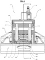
- An embodiment of the auxiliary device 1 is as in 1 and 2 recognizable, designed in such a way that a cylindrical housing 2 is guided to a mowing disc 11 with an opening let into the housing 2 in front.
- a detent 9 on the housing 2 and a transverse extension 8 on at least one piston rod 6 are pushed through a gap that is on both sides of the blade 16, or the space provided for it, between the rigid component 13 of the mower disc 11 located on the outer section and the flexible component 14 provided as a resilient holding element.
- the described positioning of the auxiliary device is also the 3 and 4 refer to.
- an opening process for the quick-release blade fastener 12 can be initiated.
- an actuating unit 7 on the auxiliary device 1 (a lever in this example) is operated, whereupon the power-operated opening process takes place.
- compressed air is applied to an actuator 4 which is supplied through connection 3 .
- At least one piston 5 is displaced downward in the vertical direction by the compressed air, as a result of which the piston rods 6 coupled to it follow the movement.
- the transverse extensions 8 attached to the piston rods 6 now displace the flexible component 14 in the intended direction (downwards) after the catch 9 on the housing 2 engages from below in the rigid component 13 of the mower disc 11, until a bolt-like component 15 is sufficiently exposed is that a knife 16 can be removed and/or used.
- the flexible component 14 is thus pressed so far down that the distance between the flexible component 14 and the bolt-like component 15 corresponds at least to the thickness of the knife 16 .
- the actuating unit 7 is now deactivated, in the case of a single-acting cylinder the piston 5 together with the piston rods 6 is pushed back into its original position by the flexible component 14 . If a double-acting cylinder is used, the activation energy can be reversed by the actuating unit in order to set the piston 5 and piston rod 6 back again. As a result, a knife, after replacement or insertion, is fixed in its position as provided by means of retaining bolts 15 between the rigid component 13 and the flexible component 14 .
- the auxiliary device 1 can now be removed from the mowing disc 11 and, if necessary, brought to the next knife quick-release fastener 12, where the process described above can be repeated in order to exchange, turn, insert or remove further knives 16.
Landscapes
- Life Sciences & Earth Sciences (AREA)
- Environmental Sciences (AREA)
- Harvester Elements (AREA)
Priority Applications (2)
| Application Number | Priority Date | Filing Date | Title |
|---|---|---|---|
| SI201630750T SI3081064T2 (sl) | 2015-04-17 | 2016-04-08 | Pomožna naprava za menjavanje nožev na poljedelskih kosilnih strojih |
| PL16000812.4T PL3081064T5 (pl) | 2015-04-17 | 2016-04-08 | Urządzenie pomocnicze do wymiany noży w kosiarce rolniczej |
Applications Claiming Priority (1)
| Application Number | Priority Date | Filing Date | Title |
|---|---|---|---|
| DE102015004944.5A DE102015004944B4 (de) | 2015-04-17 | 2015-04-17 | Hilfsvorrichtung zum Messerwechsel an landwirtschaftlichen Mähmaschinen |
Publications (3)
| Publication Number | Publication Date |
|---|---|
| EP3081064A1 EP3081064A1 (de) | 2016-10-19 |
| EP3081064B1 EP3081064B1 (de) | 2020-02-26 |
| EP3081064B2 true EP3081064B2 (de) | 2023-08-23 |
Family
ID=55802149
Family Applications (1)
| Application Number | Title | Priority Date | Filing Date |
|---|---|---|---|
| EP16000812.4A Active EP3081064B2 (de) | 2015-04-17 | 2016-04-08 | Hilfsvorrichtung zum messerwechsel an landwirtschaftlichen mähmaschinen |
Country Status (6)
| Country | Link |
|---|---|
| EP (1) | EP3081064B2 (pl) |
| DE (1) | DE102015004944B4 (pl) |
| DK (1) | DK3081064T4 (pl) |
| FI (1) | FI3081064T4 (pl) |
| PL (1) | PL3081064T5 (pl) |
| SI (1) | SI3081064T2 (pl) |
Cited By (1)
| Publication number | Priority date | Publication date | Assignee | Title |
|---|---|---|---|---|
| EP4591697A1 (de) * | 2024-01-29 | 2025-07-30 | CLAAS Saulgau GmbH | Mähorgan eines mähwerks |
Families Citing this family (2)
| Publication number | Priority date | Publication date | Assignee | Title |
|---|---|---|---|---|
| DE102015120062A1 (de) * | 2015-11-19 | 2017-05-24 | Claas Saulgau Gmbh | Vorrichtung zur Unterstützung eines Messerwechsels an Mähwerken |
| EP4104663B1 (en) | 2021-06-09 | 2026-03-11 | Techtronic Cordless GP | Quick release blade assemblies and methods for a power tool |
Citations (12)
| Publication number | Priority date | Publication date | Assignee | Title |
|---|---|---|---|---|
| DE3304199A1 (de) † | 1982-02-12 | 1983-08-25 | Osakeyhtiö Wärtsilä Ab, 00101 Helsinki | Maehvorrichtung |
| EP0717921A1 (de) † | 1994-12-21 | 1996-06-26 | Kverneland Geldrop B.V. | Kreiselmäher und Messerwechsel-Werkzeug |
| US5544862A (en) † | 1992-09-29 | 1996-08-13 | Curtiss Wright Flight Systems Inc. | Rescue tool |
| EP0809929A1 (en) † | 1996-05-29 | 1997-12-03 | Jf-Fabriken - J. Freudendahl A/S | A knife holder for a mower |
| EP1008289A1 (de) † | 1998-12-09 | 2000-06-14 | Claas Saulgau Gmbh | Messerschnellwechseleinrichtung für Mähwerke |
| DE10036552A1 (de) † | 2000-07-27 | 2002-02-07 | Karl Moosbrucker | Messerklingenbefestigung für Kreiselmähwerke |
| DE10048771A1 (de) † | 2000-09-29 | 2002-04-11 | Claas Saulgau Gmbh | Vorrichtung zum sichereren und bequemen Arbeiten mit landwirtschaftlichen Arbeitsmaschinen |
| US6829878B1 (en) † | 2004-03-29 | 2004-12-14 | Cnh America Llc | Quick change disc knife mounting mechanism |
| EP2191709A1 (en) † | 2008-10-28 | 2010-06-02 | Deere & Company | Knife holder for a rotary disk cutterbar |
| DE102009027223A1 (de) † | 2009-06-26 | 2010-12-30 | Robert Bosch Gmbh | Handgeführtes Elektrowerkzeug |
| US8302274B1 (en) † | 2010-03-01 | 2012-11-06 | Dominique Depaz | Blade removal assistance tool system |
| US20130055546A1 (en) † | 2011-09-07 | 2013-03-07 | Ii Jeffrey Fay | Disc cutterbar quick-change knife with retaining pin assembly |
-
2015
- 2015-04-17 DE DE102015004944.5A patent/DE102015004944B4/de active Active
-
2016
- 2016-04-08 DK DK16000812.4T patent/DK3081064T4/da active
- 2016-04-08 FI FIEP16000812.4T patent/FI3081064T4/fi active
- 2016-04-08 EP EP16000812.4A patent/EP3081064B2/de active Active
- 2016-04-08 PL PL16000812.4T patent/PL3081064T5/pl unknown
- 2016-04-08 SI SI201630750T patent/SI3081064T2/sl unknown
Patent Citations (12)
| Publication number | Priority date | Publication date | Assignee | Title |
|---|---|---|---|---|
| DE3304199A1 (de) † | 1982-02-12 | 1983-08-25 | Osakeyhtiö Wärtsilä Ab, 00101 Helsinki | Maehvorrichtung |
| US5544862A (en) † | 1992-09-29 | 1996-08-13 | Curtiss Wright Flight Systems Inc. | Rescue tool |
| EP0717921A1 (de) † | 1994-12-21 | 1996-06-26 | Kverneland Geldrop B.V. | Kreiselmäher und Messerwechsel-Werkzeug |
| EP0809929A1 (en) † | 1996-05-29 | 1997-12-03 | Jf-Fabriken - J. Freudendahl A/S | A knife holder for a mower |
| EP1008289A1 (de) † | 1998-12-09 | 2000-06-14 | Claas Saulgau Gmbh | Messerschnellwechseleinrichtung für Mähwerke |
| DE10036552A1 (de) † | 2000-07-27 | 2002-02-07 | Karl Moosbrucker | Messerklingenbefestigung für Kreiselmähwerke |
| DE10048771A1 (de) † | 2000-09-29 | 2002-04-11 | Claas Saulgau Gmbh | Vorrichtung zum sichereren und bequemen Arbeiten mit landwirtschaftlichen Arbeitsmaschinen |
| US6829878B1 (en) † | 2004-03-29 | 2004-12-14 | Cnh America Llc | Quick change disc knife mounting mechanism |
| EP2191709A1 (en) † | 2008-10-28 | 2010-06-02 | Deere & Company | Knife holder for a rotary disk cutterbar |
| DE102009027223A1 (de) † | 2009-06-26 | 2010-12-30 | Robert Bosch Gmbh | Handgeführtes Elektrowerkzeug |
| US8302274B1 (en) † | 2010-03-01 | 2012-11-06 | Dominique Depaz | Blade removal assistance tool system |
| US20130055546A1 (en) † | 2011-09-07 | 2013-03-07 | Ii Jeffrey Fay | Disc cutterbar quick-change knife with retaining pin assembly |
Cited By (1)
| Publication number | Priority date | Publication date | Assignee | Title |
|---|---|---|---|---|
| EP4591697A1 (de) * | 2024-01-29 | 2025-07-30 | CLAAS Saulgau GmbH | Mähorgan eines mähwerks |
Also Published As
| Publication number | Publication date |
|---|---|
| DK3081064T3 (da) | 2020-05-18 |
| SI3081064T1 (sl) | 2020-07-31 |
| DE102015004944B4 (de) | 2019-11-14 |
| PL3081064T5 (pl) | 2023-12-11 |
| DK3081064T4 (da) | 2023-11-13 |
| DE102015004944A1 (de) | 2016-10-20 |
| SI3081064T2 (sl) | 2023-12-29 |
| PL3081064T3 (pl) | 2020-08-10 |
| FI3081064T4 (fi) | 2023-11-22 |
| EP3081064A1 (de) | 2016-10-19 |
| EP3081064B1 (de) | 2020-02-26 |
Similar Documents
| Publication | Publication Date | Title |
|---|---|---|
| DE69510744T2 (de) | Schneidvorrichtung | |
| DE102014116493B4 (de) | Gegenschneideneinrichtung | |
| EP3557977B1 (de) | Wurzelballen-unterschneide- und aushebegerät | |
| EP3081064B2 (de) | Hilfsvorrichtung zum messerwechsel an landwirtschaftlichen mähmaschinen | |
| EP2386200A1 (de) | Selbstfahrender Feldhäcksler | |
| CH687237A5 (de) | Zerkleinerungsvorrichtung. | |
| EP3449710B1 (de) | Landwirtschaftliche arbeitsvorrichtung in form eines schlegelmulchers | |
| EP2805601B1 (de) | Heber für Erntegut | |
| DE102015014225B4 (de) | Mulchgerät | |
| DE102018119326B3 (de) | Doppelmesser-Schneidsystem | |
| DE102008047999B4 (de) | Akku-Gartenschere | |
| DE112014006266T5 (de) | Gartenscheren mit Schnitt-Umschaltmodus | |
| DE102014116491B4 (de) | Gegenschneideneinrichtung | |
| DE4431551C2 (de) | Brecher mit einem Gestell, in dem ein angetriebener, steinbrechender Rotor gelagert ist | |
| EP1430183B1 (de) | Schneepflug mit Räumschild, Verschleißleiste und Vorrichtung zur Befestigung der Verschleißleiste am Räumschild | |
| EP4230030B1 (de) | Laubschneidevorrichtung | |
| DE1193721B (de) | Haeckselmaschine fuer landwirtschaftliche Produkte, insbesondere Scheibenradhaecksler | |
| DE69202685T2 (de) | Silofutterschneider. | |
| EP3772890B1 (de) | Obermesserschwinghebelführung für oszillierende doppelmesserschneidsysteme | |
| DE19732252C1 (de) | Vorrichtung zur Positionierung eines Arbeitsgerätes | |
| DE202013101877U1 (de) | Bearbeitungsmaschine zum Schneiden und Sägen von Bepflanzungen | |
| DE202016104853U1 (de) | Stubbenfräse | |
| DE102012005913A1 (de) | Messerhalteeinrichtung | |
| DE60221350T2 (de) | Doppelsäge entastungsapparatus | |
| EP4635283A1 (de) | Mähbalken |
Legal Events
| Date | Code | Title | Description |
|---|---|---|---|
| PUAI | Public reference made under article 153(3) epc to a published international application that has entered the european phase |
Free format text: ORIGINAL CODE: 0009012 |
|
| AK | Designated contracting states |
Kind code of ref document: A1 Designated state(s): AL AT BE BG CH CY CZ DE DK EE ES FI FR GB GR HR HU IE IS IT LI LT LU LV MC MK MT NL NO PL PT RO RS SE SI SK SM TR |
|
| AX | Request for extension of the european patent |
Extension state: BA ME |
|
| STAA | Information on the status of an ep patent application or granted ep patent |
Free format text: STATUS: REQUEST FOR EXAMINATION WAS MADE |
|
| 17P | Request for examination filed |
Effective date: 20170410 |
|
| RBV | Designated contracting states (corrected) |
Designated state(s): AL AT BE BG CH CY CZ DE DK EE ES FI FR GB GR HR HU IE IS IT LI LT LU LV MC MK MT NL NO PL PT RO RS SE SI SK SM TR |
|
| STAA | Information on the status of an ep patent application or granted ep patent |
Free format text: STATUS: EXAMINATION IS IN PROGRESS |
|
| 17Q | First examination report despatched |
Effective date: 20170725 |
|
| GRAP | Despatch of communication of intention to grant a patent |
Free format text: ORIGINAL CODE: EPIDOSNIGR1 |
|
| STAA | Information on the status of an ep patent application or granted ep patent |
Free format text: STATUS: GRANT OF PATENT IS INTENDED |
|
| INTG | Intention to grant announced |
Effective date: 20191023 |
|
| GRAS | Grant fee paid |
Free format text: ORIGINAL CODE: EPIDOSNIGR3 |
|
| GRAA | (expected) grant |
Free format text: ORIGINAL CODE: 0009210 |
|
| STAA | Information on the status of an ep patent application or granted ep patent |
Free format text: STATUS: THE PATENT HAS BEEN GRANTED |
|
| AK | Designated contracting states |
Kind code of ref document: B1 Designated state(s): AL AT BE BG CH CY CZ DE DK EE ES FI FR GB GR HR HU IE IS IT LI LT LU LV MC MK MT NL NO PL PT RO RS SE SI SK SM TR |
|
| REG | Reference to a national code |
Ref country code: GB Ref legal event code: FG4D Free format text: NOT ENGLISH |
|
| REG | Reference to a national code |
Ref country code: CH Ref legal event code: EP |
|
| REG | Reference to a national code |
Ref country code: AT Ref legal event code: REF Ref document number: 1236501 Country of ref document: AT Kind code of ref document: T Effective date: 20200315 |
|
| REG | Reference to a national code |
Ref country code: IE Ref legal event code: FG4D Free format text: LANGUAGE OF EP DOCUMENT: GERMAN |
|
| REG | Reference to a national code |
Ref country code: DE Ref legal event code: R096 Ref document number: 502016008868 Country of ref document: DE |
|
| REG | Reference to a national code |
Ref country code: DK Ref legal event code: T3 Effective date: 20200515 |
|
| REG | Reference to a national code |
Ref country code: FI Ref legal event code: FGE |
|
| PG25 | Lapsed in a contracting state [announced via postgrant information from national office to epo] |
Ref country code: NO Free format text: LAPSE BECAUSE OF FAILURE TO SUBMIT A TRANSLATION OF THE DESCRIPTION OR TO PAY THE FEE WITHIN THE PRESCRIBED TIME-LIMIT Effective date: 20200526 Ref country code: RS Free format text: LAPSE BECAUSE OF FAILURE TO SUBMIT A TRANSLATION OF THE DESCRIPTION OR TO PAY THE FEE WITHIN THE PRESCRIBED TIME-LIMIT Effective date: 20200226 |
|
| REG | Reference to a national code |
Ref country code: NL Ref legal event code: MP Effective date: 20200226 |
|
| REG | Reference to a national code |
Ref country code: LT Ref legal event code: MG4D |
|
| PG25 | Lapsed in a contracting state [announced via postgrant information from national office to epo] |
Ref country code: HR Free format text: LAPSE BECAUSE OF FAILURE TO SUBMIT A TRANSLATION OF THE DESCRIPTION OR TO PAY THE FEE WITHIN THE PRESCRIBED TIME-LIMIT Effective date: 20200226 Ref country code: GR Free format text: LAPSE BECAUSE OF FAILURE TO SUBMIT A TRANSLATION OF THE DESCRIPTION OR TO PAY THE FEE WITHIN THE PRESCRIBED TIME-LIMIT Effective date: 20200527 Ref country code: LV Free format text: LAPSE BECAUSE OF FAILURE TO SUBMIT A TRANSLATION OF THE DESCRIPTION OR TO PAY THE FEE WITHIN THE PRESCRIBED TIME-LIMIT Effective date: 20200226 Ref country code: IS Free format text: LAPSE BECAUSE OF FAILURE TO SUBMIT A TRANSLATION OF THE DESCRIPTION OR TO PAY THE FEE WITHIN THE PRESCRIBED TIME-LIMIT Effective date: 20200626 Ref country code: BG Free format text: LAPSE BECAUSE OF FAILURE TO SUBMIT A TRANSLATION OF THE DESCRIPTION OR TO PAY THE FEE WITHIN THE PRESCRIBED TIME-LIMIT Effective date: 20200526 Ref country code: SE Free format text: LAPSE BECAUSE OF FAILURE TO SUBMIT A TRANSLATION OF THE DESCRIPTION OR TO PAY THE FEE WITHIN THE PRESCRIBED TIME-LIMIT Effective date: 20200226 |
|
| PG25 | Lapsed in a contracting state [announced via postgrant information from national office to epo] |
Ref country code: NL Free format text: LAPSE BECAUSE OF FAILURE TO SUBMIT A TRANSLATION OF THE DESCRIPTION OR TO PAY THE FEE WITHIN THE PRESCRIBED TIME-LIMIT Effective date: 20200226 |
|
| PG25 | Lapsed in a contracting state [announced via postgrant information from national office to epo] |
Ref country code: CZ Free format text: LAPSE BECAUSE OF FAILURE TO SUBMIT A TRANSLATION OF THE DESCRIPTION OR TO PAY THE FEE WITHIN THE PRESCRIBED TIME-LIMIT Effective date: 20200226 Ref country code: ES Free format text: LAPSE BECAUSE OF FAILURE TO SUBMIT A TRANSLATION OF THE DESCRIPTION OR TO PAY THE FEE WITHIN THE PRESCRIBED TIME-LIMIT Effective date: 20200226 Ref country code: SK Free format text: LAPSE BECAUSE OF FAILURE TO SUBMIT A TRANSLATION OF THE DESCRIPTION OR TO PAY THE FEE WITHIN THE PRESCRIBED TIME-LIMIT Effective date: 20200226 Ref country code: LT Free format text: LAPSE BECAUSE OF FAILURE TO SUBMIT A TRANSLATION OF THE DESCRIPTION OR TO PAY THE FEE WITHIN THE PRESCRIBED TIME-LIMIT Effective date: 20200226 Ref country code: EE Free format text: LAPSE BECAUSE OF FAILURE TO SUBMIT A TRANSLATION OF THE DESCRIPTION OR TO PAY THE FEE WITHIN THE PRESCRIBED TIME-LIMIT Effective date: 20200226 Ref country code: SM Free format text: LAPSE BECAUSE OF FAILURE TO SUBMIT A TRANSLATION OF THE DESCRIPTION OR TO PAY THE FEE WITHIN THE PRESCRIBED TIME-LIMIT Effective date: 20200226 Ref country code: PT Free format text: LAPSE BECAUSE OF FAILURE TO SUBMIT A TRANSLATION OF THE DESCRIPTION OR TO PAY THE FEE WITHIN THE PRESCRIBED TIME-LIMIT Effective date: 20200719 Ref country code: RO Free format text: LAPSE BECAUSE OF FAILURE TO SUBMIT A TRANSLATION OF THE DESCRIPTION OR TO PAY THE FEE WITHIN THE PRESCRIBED TIME-LIMIT Effective date: 20200226 |
|
| REG | Reference to a national code |
Ref country code: DE Ref legal event code: R026 Ref document number: 502016008868 Country of ref document: DE |
|
| PLBI | Opposition filed |
Free format text: ORIGINAL CODE: 0009260 |
|
| PG25 | Lapsed in a contracting state [announced via postgrant information from national office to epo] |
Ref country code: MC Free format text: LAPSE BECAUSE OF FAILURE TO SUBMIT A TRANSLATION OF THE DESCRIPTION OR TO PAY THE FEE WITHIN THE PRESCRIBED TIME-LIMIT Effective date: 20200226 |
|
| REG | Reference to a national code |
Ref country code: CH Ref legal event code: PL |
|
| PLAX | Notice of opposition and request to file observation + time limit sent |
Free format text: ORIGINAL CODE: EPIDOSNOBS2 |
|
| REG | Reference to a national code |
Ref country code: FI Ref legal event code: MDE Opponent name: CLAAS SAULGAU GMBH |
|
| 26 | Opposition filed |
Opponent name: CLAAS SAULGAU GMBH Effective date: 20201123 |
|
| PG25 | Lapsed in a contracting state [announced via postgrant information from national office to epo] |
Ref country code: LI Free format text: LAPSE BECAUSE OF NON-PAYMENT OF DUE FEES Effective date: 20200430 Ref country code: CH Free format text: LAPSE BECAUSE OF NON-PAYMENT OF DUE FEES Effective date: 20200430 Ref country code: LU Free format text: LAPSE BECAUSE OF NON-PAYMENT OF DUE FEES Effective date: 20200408 |
|
| REG | Reference to a national code |
Ref country code: BE Ref legal event code: MM Effective date: 20200430 |
|
| PG25 | Lapsed in a contracting state [announced via postgrant information from national office to epo] |
Ref country code: BE Free format text: LAPSE BECAUSE OF NON-PAYMENT OF DUE FEES Effective date: 20200430 |
|
| GBPC | Gb: european patent ceased through non-payment of renewal fee |
Effective date: 20200526 |
|
| PLBB | Reply of patent proprietor to notice(s) of opposition received |
Free format text: ORIGINAL CODE: EPIDOSNOBS3 |
|
| PG25 | Lapsed in a contracting state [announced via postgrant information from national office to epo] |
Ref country code: GB Free format text: LAPSE BECAUSE OF NON-PAYMENT OF DUE FEES Effective date: 20200526 |
|
| PG25 | Lapsed in a contracting state [announced via postgrant information from national office to epo] |
Ref country code: TR Free format text: LAPSE BECAUSE OF FAILURE TO SUBMIT A TRANSLATION OF THE DESCRIPTION OR TO PAY THE FEE WITHIN THE PRESCRIBED TIME-LIMIT Effective date: 20200226 Ref country code: MT Free format text: LAPSE BECAUSE OF FAILURE TO SUBMIT A TRANSLATION OF THE DESCRIPTION OR TO PAY THE FEE WITHIN THE PRESCRIBED TIME-LIMIT Effective date: 20200226 Ref country code: CY Free format text: LAPSE BECAUSE OF FAILURE TO SUBMIT A TRANSLATION OF THE DESCRIPTION OR TO PAY THE FEE WITHIN THE PRESCRIBED TIME-LIMIT Effective date: 20200226 |
|
| PG25 | Lapsed in a contracting state [announced via postgrant information from national office to epo] |
Ref country code: MK Free format text: LAPSE BECAUSE OF FAILURE TO SUBMIT A TRANSLATION OF THE DESCRIPTION OR TO PAY THE FEE WITHIN THE PRESCRIBED TIME-LIMIT Effective date: 20200226 Ref country code: AL Free format text: LAPSE BECAUSE OF FAILURE TO SUBMIT A TRANSLATION OF THE DESCRIPTION OR TO PAY THE FEE WITHIN THE PRESCRIBED TIME-LIMIT Effective date: 20200226 |
|
| P01 | Opt-out of the competence of the unified patent court (upc) registered |
Effective date: 20230517 |
|
| PUAH | Patent maintained in amended form |
Free format text: ORIGINAL CODE: 0009272 |
|
| STAA | Information on the status of an ep patent application or granted ep patent |
Free format text: STATUS: PATENT MAINTAINED AS AMENDED |
|
| PGFP | Annual fee paid to national office [announced via postgrant information from national office to epo] |
Ref country code: IT Payment date: 20230428 Year of fee payment: 8 Ref country code: IE Payment date: 20230425 Year of fee payment: 8 Ref country code: DK Payment date: 20230419 Year of fee payment: 8 |
|
| 27A | Patent maintained in amended form |
Effective date: 20230823 |
|
| AK | Designated contracting states |
Kind code of ref document: B2 Designated state(s): AL AT BE BG CH CY CZ DE DK EE ES FI FR GB GR HR HU IE IS IT LI LT LU LV MC MK MT NL NO PL PT RO RS SE SI SK SM TR |
|
| REG | Reference to a national code |
Ref country code: DE Ref legal event code: R102 Ref document number: 502016008868 Country of ref document: DE |
|
| PGFP | Annual fee paid to national office [announced via postgrant information from national office to epo] |
Ref country code: FI Payment date: 20230417 Year of fee payment: 8 |
|
| REG | Reference to a national code |
Ref country code: DK Ref legal event code: T4 Effective date: 20231107 |
|
| REG | Reference to a national code |
Ref country code: DK Ref legal event code: EBP Effective date: 20240430 |
|
| PG25 | Lapsed in a contracting state [announced via postgrant information from national office to epo] |
Ref country code: FI Free format text: LAPSE BECAUSE OF NON-PAYMENT OF DUE FEES Effective date: 20240408 |
|
| PG25 | Lapsed in a contracting state [announced via postgrant information from national office to epo] |
Ref country code: FI Free format text: LAPSE BECAUSE OF NON-PAYMENT OF DUE FEES Effective date: 20240408 |
|
| PG25 | Lapsed in a contracting state [announced via postgrant information from national office to epo] |
Ref country code: DK Free format text: LAPSE BECAUSE OF NON-PAYMENT OF DUE FEES Effective date: 20240430 |
|
| PG25 | Lapsed in a contracting state [announced via postgrant information from national office to epo] |
Ref country code: IE Free format text: LAPSE BECAUSE OF NON-PAYMENT OF DUE FEES Effective date: 20240408 |
|
| PGFP | Annual fee paid to national office [announced via postgrant information from national office to epo] |
Ref country code: SI Payment date: 20250326 Year of fee payment: 10 |
|
| PGFP | Annual fee paid to national office [announced via postgrant information from national office to epo] |
Ref country code: PL Payment date: 20250327 Year of fee payment: 10 |
|
| PG25 | Lapsed in a contracting state [announced via postgrant information from national office to epo] |
Ref country code: IT Free format text: LAPSE BECAUSE OF NON-PAYMENT OF DUE FEES Effective date: 20240408 |
|
| PGFP | Annual fee paid to national office [announced via postgrant information from national office to epo] |
Ref country code: DE Payment date: 20250417 Year of fee payment: 10 |
|
| PGFP | Annual fee paid to national office [announced via postgrant information from national office to epo] |
Ref country code: FR Payment date: 20250422 Year of fee payment: 10 |
|
| PGFP | Annual fee paid to national office [announced via postgrant information from national office to epo] |
Ref country code: AT Payment date: 20250416 Year of fee payment: 10 |