EP3081064B2 - Auxiliary device for knife change on agricultural grass-cutter mowing machines - Google Patents
Auxiliary device for knife change on agricultural grass-cutter mowing machines Download PDFInfo
- Publication number
- EP3081064B2 EP3081064B2 EP16000812.4A EP16000812A EP3081064B2 EP 3081064 B2 EP3081064 B2 EP 3081064B2 EP 16000812 A EP16000812 A EP 16000812A EP 3081064 B2 EP3081064 B2 EP 3081064B2
- Authority
- EP
- European Patent Office
- Prior art keywords
- auxiliary device
- quick
- actuator
- component
- release
- Prior art date
- Legal status (The legal status is an assumption and is not a legal conclusion. Google has not performed a legal analysis and makes no representation as to the accuracy of the status listed.)
- Active
Links
- 238000000034 method Methods 0.000 claims description 12
- 230000008569 process Effects 0.000 claims description 12
- 239000012530 fluid Substances 0.000 claims description 2
- 238000004146 energy storage Methods 0.000 claims 2
- 239000000969 carrier Substances 0.000 description 3
- 238000011161 development Methods 0.000 description 3
- 230000018109 developmental process Effects 0.000 description 3
- 230000001960 triggered effect Effects 0.000 description 3
- 230000004913 activation Effects 0.000 description 2
- 238000012423 maintenance Methods 0.000 description 2
- 239000000463 material Substances 0.000 description 2
- 239000002689 soil Substances 0.000 description 2
- 239000002028 Biomass Substances 0.000 description 1
- 229910000831 Steel Inorganic materials 0.000 description 1
- 208000027418 Wounds and injury Diseases 0.000 description 1
- 230000008878 coupling Effects 0.000 description 1
- 238000010168 coupling process Methods 0.000 description 1
- 238000005859 coupling reaction Methods 0.000 description 1
- 230000006378 damage Effects 0.000 description 1
- 208000014674 injury Diseases 0.000 description 1
- 238000003780 insertion Methods 0.000 description 1
- 230000037431 insertion Effects 0.000 description 1
- 239000002245 particle Substances 0.000 description 1
- 230000001681 protective effect Effects 0.000 description 1
- 230000008439 repair process Effects 0.000 description 1
- 238000005096 rolling process Methods 0.000 description 1
- 125000006850 spacer group Chemical group 0.000 description 1
- 239000010959 steel Substances 0.000 description 1
Images


Classifications
-
- A—HUMAN NECESSITIES
- A01—AGRICULTURE; FORESTRY; ANIMAL HUSBANDRY; HUNTING; TRAPPING; FISHING
- A01D—HARVESTING; MOWING
- A01D34/00—Mowers; Mowing apparatus of harvesters
- A01D34/01—Mowers; Mowing apparatus of harvesters characterised by features relating to the type of cutting apparatus
- A01D34/412—Mowers; Mowing apparatus of harvesters characterised by features relating to the type of cutting apparatus having rotating cutters
- A01D34/63—Mowers; Mowing apparatus of harvesters characterised by features relating to the type of cutting apparatus having rotating cutters having cutters rotating about a vertical axis
- A01D34/82—Other details
-
- A—HUMAN NECESSITIES
- A01—AGRICULTURE; FORESTRY; ANIMAL HUSBANDRY; HUNTING; TRAPPING; FISHING
- A01D—HARVESTING; MOWING
- A01D34/00—Mowers; Mowing apparatus of harvesters
- A01D34/01—Mowers; Mowing apparatus of harvesters characterised by features relating to the type of cutting apparatus
- A01D34/412—Mowers; Mowing apparatus of harvesters characterised by features relating to the type of cutting apparatus having rotating cutters
- A01D34/63—Mowers; Mowing apparatus of harvesters characterised by features relating to the type of cutting apparatus having rotating cutters having cutters rotating about a vertical axis
- A01D34/73—Cutting apparatus
- A01D34/733—Cutting-blade mounting means
Definitions
- the invention relates to an auxiliary device for changing knives on an agricultural mower according to the preamble of patent claim 1.
- Mowing machines are regularly used in agricultural field cultivation, in order to preferably process stalk-type biomass.
- Modern mowers are often designed as rotary mowers.
- a common structure of these machines consists of a device for coupling to a tractor, a base frame and a mowing bar, on which in turn a large number of rotating cutting unit carriers, so-called mowing discs, are mounted.
- Such knife quick-release fasteners and associated tools are known from practice in numerous designs.
- quick-action knife fasteners refer to the EP 2 191 709 A1 referred.
- the designs of these knife quick-release fasteners are diverse, but follow a comparable principle.
- Two basic components are usually used, a rigid component and a flexible component for the pivotable mounting of the knives, with a retaining bolt or bolt-like component on one of the two components being inserted into a hole in a knife and, if necessary, also into a hole in the opposite part to the bolt-like component Component is engaged.
- the flexible member can be displaced by a lever to allow a knife to be detached from the bolt-like member or inserted.
- Such manual auxiliary devices are, for example, from EP 1 008 289 A1 known.
- the DE 100 48 771 A1 discloses a device for safe and convenient working with agricultural working machines, with which a safe and convenient exchange of work tools on the tool carriers of the working machines can be carried out. Because of the wide variety of attachment options between work tools and their tool carriers, this document focuses on screw connections with which knives are attached to rotary-driven mower discs. In this context, it should be noted that bolted connections used to fasten the blades on mower discs certainly cannot be considered quick-action blade fasteners, since the bolt heads or nuts of these bolted connections must first be cleaned of soil or crop buildup in a time-consuming process before a tool can be used to loosen the bolted connection can become effective at all. In paragraphs [0002] and [0003] these differences are first clearly highlighted. In the further course of the description documents, however, there is no reference whatsoever to the use of fastening means other than the screw connection for fastening the blades to the mower discs.
- a pin element is used as a further securing means, which is inserted into the lower end of the shank of the retaining bolt and, in the locked state, engages under a retaining structure inside the pivot bushing.
- the object of the invention is therefore to offer an auxiliary device which minimizes the disadvantages arising from the prior art and thus reduces the effort and time required when removing or fitting knives on a mower disc with quick-action knife fastener on a mower and at the same time Increased occupational safety.
- drive energy actuation should be understood as meaning the use of an energy source to carry out the desired actions.
- pneumatic, hydraulic, or electrical power can be considered.
- the invention provides for the auxiliary device to be connected to a source of drive energy or to charge a storage device for the drive energy used before use in order to then bring the auxiliary device to a mower disc with a quick-release blade fastener. There, an opening process is triggered, after which the knife can be removed and/or inserted, in order to then fix a knife in a quick-release knife fastener by a triggered closing process, so that the auxiliary device operated with drive energy can then be removed and/or guided to the next area of use.
- auxiliary device to be constructed with at least one fluid-operated piston-cylinder unit that acts in the vertical direction and is equipped with two vertically-operating piston rods with horizontally aligned flat material, in order to be locked together with a lock on the auxiliary device in one otherwise intended for levers.
- the auxiliary device To be recognized gap between the rigid and the flexible component of the mower disc.
- the quick-release knife fastener is designed in such a way that a rigid component is designed as the external section of a knife disc, while the flexible component is a resiliently yielding holding element.
- one of the two components is provided with a bolt-like component, which is brought into engagement with a through hole in the knife and a bore in the component opposite the bolt-like component, so that said knife is fixed pivotably and securely in the intended position.
- electrically driven linear drives instead of the piston-cylinder units listed above is also conceivable here.
- piston-cylinder units do not work vertically but horizontally, with a wedge-shaped attachment being attached to the end of at least one piston rod.
- this attachment is responsible for displacing the flexible component on a quick-release knife fastener.
- two mutually aligned piston-cylinder units can be used, or one piston-cylinder unit in conjunction with a lock on the auxiliary device, in order to hold a mowing disc in position when the blade quick-release fastener is opened.
- the use of fluid-operated as well as electronically operated linear drives is conceivable.
- At least one rotary drive can be used in an auxiliary device in order to adjust a lever movement after such an auxiliary device has been brought up to the mower disc with a quick-action blade lock.
- a spring-mounted component is thus displaced in the intended direction by a rotary movement of the at least one rotary drive, in that a flat material, for example flat steel, is coupled to said drive and inserted into the gap provided for a lever between a spring-mounted component and a is performed on the outer section of the mower disc and, when the rotary movement of a rotary drive is triggered, ensures that the flexible component is displaced.
- a flat material for example flat steel
- a mowing machine or self-propelled work machine could have storage space and/or storage areas for an auxiliary device and corresponding supply lines, such as air hoses, hydraulic hoses, power cables or the like, possibly also in a rollable or self-rolling form.
- a modern rotary mower consists of a housing which can be equipped with safety devices such as spacers or protective covers, among other things.
- An essential part of such a rotary mower is a cutterbar 10, as in 1 shown.
- Mowing disks 11 of various designs can be mounted on such a mowing bar 10 .
- the mower discs 11 are elliptical.
- These mower discs 11 have a quick-release blade fastener 12 which is constructed in such a way that a rigid component 13, in this case an external section of the mower disc 11, is designed to be provided with a bolt-like component 15, designed here as a retaining bolt.
- This is provided with a through-opening on a blade 16 provided for the mower disc 11 and a through-opening on a flexible component 14, in 3 seen as a resilient retaining member, engaged to pivotally fix the blade 16 in position on the mower disc 11.
- An embodiment of the auxiliary device 1 is as in 1 and 2 recognizable, designed in such a way that a cylindrical housing 2 is guided to a mowing disc 11 with an opening let into the housing 2 in front.
- a detent 9 on the housing 2 and a transverse extension 8 on at least one piston rod 6 are pushed through a gap that is on both sides of the blade 16, or the space provided for it, between the rigid component 13 of the mower disc 11 located on the outer section and the flexible component 14 provided as a resilient holding element.
- the described positioning of the auxiliary device is also the 3 and 4 refer to.
- an opening process for the quick-release blade fastener 12 can be initiated.
- an actuating unit 7 on the auxiliary device 1 (a lever in this example) is operated, whereupon the power-operated opening process takes place.
- compressed air is applied to an actuator 4 which is supplied through connection 3 .
- At least one piston 5 is displaced downward in the vertical direction by the compressed air, as a result of which the piston rods 6 coupled to it follow the movement.
- the transverse extensions 8 attached to the piston rods 6 now displace the flexible component 14 in the intended direction (downwards) after the catch 9 on the housing 2 engages from below in the rigid component 13 of the mower disc 11, until a bolt-like component 15 is sufficiently exposed is that a knife 16 can be removed and/or used.
- the flexible component 14 is thus pressed so far down that the distance between the flexible component 14 and the bolt-like component 15 corresponds at least to the thickness of the knife 16 .
- the actuating unit 7 is now deactivated, in the case of a single-acting cylinder the piston 5 together with the piston rods 6 is pushed back into its original position by the flexible component 14 . If a double-acting cylinder is used, the activation energy can be reversed by the actuating unit in order to set the piston 5 and piston rod 6 back again. As a result, a knife, after replacement or insertion, is fixed in its position as provided by means of retaining bolts 15 between the rigid component 13 and the flexible component 14 .
- the auxiliary device 1 can now be removed from the mowing disc 11 and, if necessary, brought to the next knife quick-release fastener 12, where the process described above can be repeated in order to exchange, turn, insert or remove further knives 16.
Description
Die Erfindung betrifft eine Hilfsvorrichtung zum Messerwechseln an einer landwirtschaftlichen Mähmaschine nach dem Oberbegriff des Patentanspruchs 1.The invention relates to an auxiliary device for changing knives on an agricultural mower according to the preamble of
In der landwirtschaftlichen Feldbearbeitung werden regelmäßig Mähmaschinen eingesetzt, um vorzugsweise halmgutartige Biomasse zu bearbeiten. Moderne Mähmaschinen sind häufig als Rotationsmähwerke ausgeführt. Ein gängiger Aufbau dieser Maschinen besteht aus einer Vorrichtung zum Koppeln an einen Traktor, einem Grundgestell und einem Mähholm, auf dem wiederum eine Vielzahl von rotierenden Schneidwerkträgern, sogenannten Mähscheiben montiert sind. Durch den heutzutage häufigen Einsatz dieser Mähmaschinen, oft drei bis fünf Einsätze pro zu bearbeitender Fläche in einer Saison und dem Umstand, dass die Mähmaschinen zumeist in Bodennähe oder unmittelbar auf dem Boden aufliegend arbeiten, leiden die Messer unter erhöhtem Verschleiß durch Kontakt mit Bodenpartikeln oder darauf befindlichen Gegenständen, beispielsweise Steinen. Daraus resultierte die Notwendigkeit einer vereinfachten Montage der an den Mähscheiben befindlichen Messer, was die Entwicklung von Messerschnellverschlüssen zur Folge hatte.Mowing machines are regularly used in agricultural field cultivation, in order to preferably process stalk-type biomass. Modern mowers are often designed as rotary mowers. A common structure of these machines consists of a device for coupling to a tractor, a base frame and a mowing bar, on which in turn a large number of rotating cutting unit carriers, so-called mowing discs, are mounted. Due to the frequent use of these mowers nowadays, often three to five uses per area to be worked in one season and the fact that the mowers mostly work close to the ground or directly on the ground, the knives suffer from increased wear through contact with soil particles or on them located objects, such as stones. This resulted in the need for a simplified assembly of the knives on the mower discs, which led to the development of quick-release knife fasteners.
Derartige Messerschnellverschlüsse und dazugehörige Werkzeuge sind aus der Praxis in zahlreichen Ausführungen bekannt. Als Beispiel für solche Messerschnellverschlüsse sei auf die
Die
Aus der
Bei Wartungs- oder Instandhaltungsmaßnahmen, welche den Tausch mehrerer oder aller Messer an einer Mähmaschine vorsehen, entsteht durch die zunehmende Arbeitsbreite, der damit einhergehenden erhöhten Anzahl von Mähscheiben und somit der verbauten, zu wechselnden Messer in modernen Mähmaschinen und/oder Mähkombinationen, trotz Vereinfachung durch Hebeleinsatz, ein enormer Kraft- und Zeitaufwand, sowie eine mögliche Verletzungsgefahr durch Abrutschen des Hebels oder Quetschgefahr durch zurückschnellende flexible Bauteile.In the case of maintenance or repair measures that require the replacement of several or all blades on a mower, the increasing working width, the associated increase in the number of mower discs and the built-in blades that need to be changed in modern mowers and/or mower combinations, despite the simplification Lever use, an enormous amount of effort and time, as well as a possible risk of injury from the lever slipping or the risk of crushing from flexible components snapping back.
Aufgabe der Erfindung ist es daher, eine Hilfsvorrichtung anzubieten, welche die Nachteile, die sich aus dem Stand der Technik ergeben, minimiert und somit Kraft- und Zeitaufwand bei der Entnahme oder Bestückung von Messern an einer Mähscheibe mit Messerschnellverschluss an einer Mähmaschine verringert und gleichzeitig die Arbeitssicherheit erhöht.The object of the invention is therefore to offer an auxiliary device which minimizes the disadvantages arising from the prior art and thus reduces the effort and time required when removing or fitting knives on a mower disc with quick-action knife fastener on a mower and at the same time Increased occupational safety.
Erfindungsgemäß wird diese Aufgabe durch die kennzeichnenden Merkmale des Anspruchs 1 gelöst. Vorteilhafte Weiterbildungen der Erfindung sind Gegenstand der weiteren Ansprüche und Ausführungsbeispiele,According to the invention, this object is achieved by the characterizing features of
Gemäß der Erfindung wird eine Hilfsvorrichtung zum Wechseln von Messern einer Mähmaschine mit einem, zumindest zwei rotierende Mähscheiben aufweisenden, Mähholm vorgeschlagen, wobei die Messer über einen Messerschnellverschluss mit der Mähscheibe verbunden sind, wobei der Messerschnellverschluss ein flexibles Bauteil umfasst, das als ein federnd nachgiebiges Halteelement ausgebildet ist, wobei die an die Mähschelbe herangeführte Hilfsvorrichtung dazu eingerichtet ist, den Messerschnellverschluss antriebsenergiebetätigt zum Aus- bzw. Einbau eines Messers zu öffnen und nach dem Aus- bzw. Einbau des Messers wieder zu verschließen, wobei der antriebsenergiebetätigte Öffnungs- und Schließvorgang des Messerschnellverschlusses durch wenigstens einen Aktor der Hilfsvorrichtung ausführbar ist, der dazu eingerichtet Ist, den Öffnungs- und Schließvorgang durch Verlagerung des flexiblen Bauteils In eine vorgesehene Richtung auszuführen.According to the invention, an auxiliary device for changing the blades of a mowing machine with a mowing bar having at least two rotating mowing discs, the blades being connected to the mowing disc via a quick-release blade fastener, the quick-release blade fastener comprising a flexible component which is designed as a resilient retaining element, the on the auxiliary device brought up to the mower disc is set up to open the quick-acting knife closure by drive energy for removing or installing a knife and to close it again after the knife has been removed or installed, the opening and closing process of the quick-acting knife closure actuated by drive energy being carried out by at least one actuator of the auxiliary device can be carried out, which is set up to carry out the opening and closing process by displacing the flexible component in an intended direction.
Unter dem Begriff der Antriebsenergiebetätigung soll in diesem Zusammenhang der Einsatz eines Energieträgers zur Ausführung der gewünschten Aktionen verstanden werden. So können beispielsweise pneumatische, hydraulische oder elektrische Energie in Betracht gezogen werden. Dabei sieht die Erfindung vor, die Hilfsvorrichtung an eine Antriebsenergiequelle anzuschließen, oder einen Speicher für verwendete Antriebsenergie vor Gebrauch aufzuladen, um im Anschluss die Hilfsvorrichtung an eine Mähscheibe mit Messerschnellverschluss heranzuführen. Dort wird ein Öffnungsvorgang ausgelöst, wonach das Messer entnommen und/oder eingesetzt werden kann, um im Anschluss daran durch einen ausgelösten Schließvorgang ein Messer in einem Messerschnellverschluss zu fixieren, sodass daraufhin die antriebsenergiebetriebene Hilfsvorrichtung entfernt und/oder an den nächsten Einsatzbereich geführt werden kann.In this context, the term “drive energy actuation” should be understood as meaning the use of an energy source to carry out the desired actions. For example, pneumatic, hydraulic, or electrical power can be considered. The invention provides for the auxiliary device to be connected to a source of drive energy or to charge a storage device for the drive energy used before use in order to then bring the auxiliary device to a mower disc with a quick-release blade fastener. There, an opening process is triggered, after which the knife can be removed and/or inserted, in order to then fix a knife in a quick-release knife fastener by a triggered closing process, so that the auxiliary device operated with drive energy can then be removed and/or guided to the next area of use.
Eine Ausführung sieht hierbei vor, die Hilfsvorrichtung mit wenigstens einer, in vertikaler Richtung wirkenden, fluidbetriebenen Kolbenzylindereinheit aufzubauen, welche mit zwei vertikal arbeitenden Kolbenstangen mit horizontal ausgerichtetem Flachmaterial ausgestattet ist, um mit einer Arretierung an der Hilfsvorrichtung gemeinsam in einen, sonst für Hebel vorgesehenen, Spalt zwischen dem starren und dem flexiblen Bauteil der Mähscheibe angesetzt zu werden. Durch Beaufschlagen des fluidbetriebenen Zylinders mit entsprechender Antriebsenergie wird nun das flexible Bauteil der Mähscheibe durch eine vertikal ausgerichtete Bewegung verdrängt, sodass der Messerschnellverschluss geöffnet wird und ein Messer eingesetzt oder entnommen werden kann.One embodiment provides for the auxiliary device to be constructed with at least one fluid-operated piston-cylinder unit that acts in the vertical direction and is equipped with two vertically-operating piston rods with horizontally aligned flat material, in order to be locked together with a lock on the auxiliary device in one otherwise intended for levers. To be recognized gap between the rigid and the flexible component of the mower disc. By applying the appropriate drive energy to the fluid-operated cylinder, the flexible component of the mower disc is now displaced by a vertically oriented movement, so that the quick-release blade fastener is opened and a blade can be inserted or removed.
Dabei ist der Messerschnellverschluss derart konzipiert, dass ein starres Bauteil als außenliegender Abschnitt einer Messerscheibe ausgeprägt ist, während der flexible Bauteil ein federnd nachgiebiges Halteelement ist. Zusätzlich ist eines der beiden Bauteile mit einem bolzenähnlichen Bauteil versehen, welches mit einer im Messer befindlichen Durchgangsbohrung und einer Bohrung in dem, dem bolzenähnlichen Bauteil gegenüberliegendem Bauteil in Eingriff gebracht wird, sodass besagtes Messer schwenkbeweglich und sicher in der vorgesehenen Position fixiert wird. Hierbei ist auch der Einsatz von elektrisch angetriebenen Linearantrieben anstelle der oben aufgeführten Kolbenzylindereinheiten denkbar.The quick-release knife fastener is designed in such a way that a rigid component is designed as the external section of a knife disc, while the flexible component is a resiliently yielding holding element. In addition, one of the two components is provided with a bolt-like component, which is brought into engagement with a through hole in the knife and a bore in the component opposite the bolt-like component, so that said knife is fixed pivotably and securely in the intended position. The use of electrically driven linear drives instead of the piston-cylinder units listed above is also conceivable here.
In einer weiteren erfindungsgemäßen Ausführung arbeiten Kolbenzylindereinheiten nicht vertikal, sondern horizontal, wobei am Ende wenigstens einer Kolbenstange ein keilförmiger Aufsatz angebracht wird. Dieser Aufsatz ist bei Beaufschlagung der Kolbenzylindereinheiten mit Antriebsenergie für eine Verdrängung des flexiblen Bauteils an einem Messerschnellverschluss verantwortlich. Hierbei können beispielsweise zwei gegeneinander ausgerichtete Kolbenzylindereinheiten eingesetzt werden, oder eine Kolbenzylindereinheit im Verbund mit einer Arretierung an der Hilfseinrichtung, um eine Mähscheibe bei einem Öffnungsvorgang des Messerschnellverschlusses in Position zu halten. Auch hierbei ist sowohl der Einsatz von fluidbetriebenen, als auch elektronisch betriebenen Linearantrieben denkbar.In a further embodiment according to the invention, piston-cylinder units do not work vertically but horizontally, with a wedge-shaped attachment being attached to the end of at least one piston rod. When the piston-cylinder units are subjected to drive energy, this attachment is responsible for displacing the flexible component on a quick-release knife fastener. Here, for example, two mutually aligned piston-cylinder units can be used, or one piston-cylinder unit in conjunction with a lock on the auxiliary device, in order to hold a mowing disc in position when the blade quick-release fastener is opened. Here, too, the use of fluid-operated as well as electronically operated linear drives is conceivable.
Weiterhin kann erfindungsgemäß wenigstens ein Rotationsantrieb in einer Hilfsvorrichtung eingesetzt werden, um somit eine Hebelbewegung nachzustellen, nachdem eine derartige Hilfsvorrichtung an der Mähscheibe mit Messerschnellverschluss herangeführt worden ist. Somit wird also ein federnd gelagertes Bauteil durch eine Drehbewegung des wenigstens einen Rotationsantriebs in vorgesehener Richtung verlagert, indem ein Flachmaterial, beispielsweise ein Flachstahl, an dem besagten Antrieb gekoppelt ist und in den, für einen Hebel vorgesehenen, Spalt zwischen einem federnd gelagerten Bauteil und einem außenliegenden Abschnitt der Mähscheibe geführt wird und bei Auslösen der Drehbewegung eines Rotationsantriebs für die Verdrängung des flexiblen Bauteils sorgt. Abermals kann sowohl die Verwendung von fluidbetriebenen, als auch elektronisch betriebenen Rotationsantrieben in Betracht gezogen werden.Furthermore, according to the invention, at least one rotary drive can be used in an auxiliary device in order to adjust a lever movement after such an auxiliary device has been brought up to the mower disc with a quick-action blade lock. A spring-mounted component is thus displaced in the intended direction by a rotary movement of the at least one rotary drive, in that a flat material, for example flat steel, is coupled to said drive and inserted into the gap provided for a lever between a spring-mounted component and a is performed on the outer section of the mower disc and, when the rotary movement of a rotary drive is triggered, ensures that the flexible component is displaced. Again, the use of fluid powered as well as electronically powered rotary drives can be envisaged.
In einer Weiterbildung der Erfindung kann es vorgesehen sein, eine Hilfsvorrichtung an einer Mähmaschine, insbesondere einer selbstfahrenden Arbeitsmaschine mit Mähwerken, anzubringen, bzw. unterzubringen. Demnach könnte eine Mähmaschine oder selbstfahrende Arbeitsmaschine über Stauraum und/oder Stauflächen für eine Hilfsvorrichtung und entsprechende Zuleitungen, wie Luftschläuchen, Hydraulikschläuchen, Stromkabeln oder ähnliches verfügen, denkbarerweise auch in aufrollbarer oder selbstaufrollender Form.In a further development of the invention, provision can be made for attaching or accommodating an auxiliary device to a mower, in particular a self-propelled work machine with mowers. Accordingly, a mowing machine or self-propelled work machine could have storage space and/or storage areas for an auxiliary device and corresponding supply lines, such as air hoses, hydraulic hoses, power cables or the like, possibly also in a rollable or self-rolling form.
Eine detaillierte Beschreibung eines Gegenstandes der Erfindung erfolgt nun anhand eines Ausführungsbeispiels. In der Zeichnung wird folgendes dargestellt:
-
Fig. 1 : eine perspektivische Darstellung eines Mähholmes mit einer herangeführten Ausführungsvariante einer Hilfsvorrichtung; -
Fig. 2 : einen Ausschnitt ausFig. 1 mit vergrößerter Ansicht einer Ausführung der Hilfsvorrichtung; -
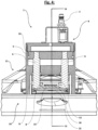
Fig. 3 : einen Längsschnitt einer Hilfsvorrichtung an einem, auf einem Mähholm montierten, Messerteller gemäß Schnitt III-III inFig. 2 ; -
Fig. 4 : einen Querschnitt einer Hilfsvorrichtung an einem, auf einem Mähholm montierten, Messerteller gemäß Schnitt IV-IV inFig. 3
-
1 1: a perspective view of a mowing bar with an approached embodiment variant of an auxiliary device; -
2 : asnippet 1 with an enlarged view of an embodiment of the auxiliary device; -
3 : a longitudinal section of an auxiliary device on a cutter bar mounted on a cutter bar according to section III-III in2 ; -
4 : a cross section of an auxiliary device on a cutter bar mounted on a cutter bar according to section IV-IV in3
- 1) Hilfsvorrichtung1) Auxiliary device
- 2) Gehäuse2) housing
- 3) Anschluss für Antriebsenergie3) Connection for drive power
- 4) Aktor (Linearantrieb)4) actuator (linear drive)
- 5) Kolben5) piston
- 6) Kolbenstange6) Piston rod
- 7) Betätigungseinheit7) operating unit
- 8) Querfortsatz8) transverse process
- 9) Arretierung9) detent
- 10) Mähholm10) Cutter bar
- 11) Mähscheibe11) Mowing disc
- 12) Messerschnellverschluss12) Knife quick release
- 13) starres Bauteil13) rigid component
- 14) flexibles Bauteil14) flexible component
- 15) bolzenähnliches Bauteil15) bolt-like component
- 16) Messer16) knife
Viele moderne Rotationsmähwerke verwenden ein System zur schnelleren Durchführung von Messerwartung/-wechseln, einem so genannten Messerschnellverschluss 12.Many modern rotary mowers use a system to perform blade maintenance/changes faster called a
Eine Ausführung eines modernen Rotationsmähwerks besteht aus einem Gehäuse, welches u.a. mit Sicherheitsvorrichtungen wie Abstandshaltern oder Schutzabdeckungen ausgerüstet sein kann. Ein essentieller Teil eines solchen Rotationsmähwerks ist ein Mähholm 10, wie in
Eine Ausführung der Hilfsvorrichtung 1 ist, wie in
Nachdem die Hilfsvorrichtung 1 wie beschrieben in Stellung an einer Mähscheibe 11 angebracht ist, kann ein Öffnungsvorgang des Messerschnellverschlusses 12 eingeleitet werden. Hierzu wird eine Betätigungseinheit 7 an der Hilfsvorrichtung 1 (in diesem Beispiel ein Hebel) bedient, worauf der antriebsenergiebetätigte Öffnungsvorgang erfolgt. In dieser Ausführung wird beispielsweise nach der Aktivierung durch den Bediener also ein Aktor 4 mit Druckluft beaufschlagt, welcher durch den Anschluss 3 versorgt wird. Durch die Druckluft wird wenigstens ein Kolben 5 in vertikaler Richtung nach unten verdrängt, wodurch die daran gekoppelten Kolbenstangen 6 der Bewegung folgen. Die an den Kolbenstangen 6 angebrachten Querfortsätze 8 verdrängen jetzt, nachdem die Arretierung 9 an dem Gehäuse 2 von unten in das starre Bauteil 13 der Mähscheibe 11 greift, das flexible Bauteil 14 in vorgesehener Richtung (abwärts), bis ein bolzenähnliches Bauteil 15 weit genug freigelegt ist, dass ein Messer 16 entnommen, und/oder eingesetzt werden kann. Das flexible Bauteil 14 wird also so weit nach unten gedrückt, dass der Abstand zwischen flexiblem Bauteil 14 und dem bolzenähnlichen Bauteil 15 mindestens der Stärke des Messers 16 entspricht.After the
Wird jetzt die Betätigungseinheit 7 deaktiviert, so wird im Falle eines einfach wirkenden Zylinders der Kolben 5 samt Kolbenstangen 6 durch das flexible Bauteil 14 wieder in seine Ursprungsposition zurück geschoben. Sollte ein doppelt wirkender Zylinder eingesetzt werden, kann die Aktivierungsenergie durch die Betätigungseinheit reversiert werden, um so Kolben 5 und Kolbenstangen 6 wieder zurück zu stellen. Damit einhergehend wird ein Messer, nach dem Austausch oder Einsetzen, wie vorgesehen mittels Haltebolzen 15 zwischen dem starren Bauteil 13 und dem flexiblen Bauteil 14 in seiner Position fixiert.If the
Die Hilfsvorrichtung 1 kann nun von der Mähscheibe 11 entfernt werden und gegebenenfalls an den nächsten Messerschnellverschluss 12 herangeführt werden, wo der oben beschriebene Vorgang wiederholt werden kann, um weitere Messer 16 zu tauschen, zu wenden, einzusetzen oder zu entfernen.The
Claims (10)
- Auxiliary device (1) for changing blades (16) of a mower comprising a cutterbar (10) that has at least two rotating cutting discs (11), the blades (16) being connected to the cutting disc (11) by a quick-release blade fastener (12), the quick-release blade fastener (12) comprising a flexible component (14) which is designed as a resiliently flexible holding element, the auxiliary device (1) which is brought up to the cutting disc (11) being configured to open the quick-release blade fastener (12) in a manner actuated by drive energy in order to remove and/or install a blade (16) and to close the quick-release blade fastener again after the blade (16) has been removed and/or installed, characterized in that the drive energy-actuated opening and closing process of the quick-release blade fastener (12) is carried out by at least one actuator (4) of the auxiliary device (1), which actuator is configured to carry out the opening and closing process of the quick-release blade fastener (12) by moving the flexible component (14) in a designated direction, the quick-release blade fastener (12) to be actuated consisting of a rigid component (13), the flexible component (14) and a bolt-like component (15), by means of which a blade (16) is fixed in its position so as to be pivotable on the cutting disc (11).
- Auxiliary device (1) according to Claim 1, characterized in that at least one actuator (4) can be operated so as to act in a vertical direction.
- Auxiliary device (1) according to Claim 1, characterized in that at least one actuator (4) can be operated so as to act in a horizontal direction.
- Auxiliary device (1) according to any of the preceding claims, characterized in that the at least one actuator (4) is a linear drive.
- Auxiliary device (1) according to any of the preceding claims, characterized in that the at least one actuator (4) is a rotary drive.
- Auxiliary device (1) according to any of the preceding claims, characterized in that at least one actuator (4) can be operated by means of a fluid.
- Auxiliary device (1) according to Claims 1 to 5, characterized in that at least one actuator (4) can be operated by means of electrical power.
- Auxiliary device (1) according to Claim 1, characterized in that the rigid component (13) of the quick-release blade fastener (12) is designed as an outer portion of the cutting disc (11).
- Auxiliary device (1) according to Claim 7, characterized in that the electrical power used is derived from a mobile energy storage means.
- Auxiliary device (1) according to Claim 9, characterized in that the mobile energy storage means is rechargeable.
Priority Applications (2)
| Application Number | Priority Date | Filing Date | Title |
|---|---|---|---|
| PL16000812.4T PL3081064T5 (en) | 2015-04-17 | 2016-04-08 | Auxiliary device for knife change on agricultural grass-cutter mowing machines |
| SI201630750T SI3081064T2 (en) | 2015-04-17 | 2016-04-08 | Auxiliary device for knife change on agricultural grass-cutter mowing machines |
Applications Claiming Priority (1)
| Application Number | Priority Date | Filing Date | Title |
|---|---|---|---|
| DE102015004944.5A DE102015004944B4 (en) | 2015-04-17 | 2015-04-17 | Auxiliary device for changing blades on agricultural mowers |
Publications (3)
| Publication Number | Publication Date |
|---|---|
| EP3081064A1 EP3081064A1 (en) | 2016-10-19 |
| EP3081064B1 EP3081064B1 (en) | 2020-02-26 |
| EP3081064B2 true EP3081064B2 (en) | 2023-08-23 |
Family
ID=55802149
Family Applications (1)
| Application Number | Title | Priority Date | Filing Date |
|---|---|---|---|
| EP16000812.4A Active EP3081064B2 (en) | 2015-04-17 | 2016-04-08 | Auxiliary device for knife change on agricultural grass-cutter mowing machines |
Country Status (6)
| Country | Link |
|---|---|
| EP (1) | EP3081064B2 (en) |
| DE (1) | DE102015004944B4 (en) |
| DK (1) | DK3081064T4 (en) |
| FI (1) | FI3081064T4 (en) |
| PL (1) | PL3081064T5 (en) |
| SI (1) | SI3081064T2 (en) |
Families Citing this family (2)
| Publication number | Priority date | Publication date | Assignee | Title |
|---|---|---|---|---|
| DE102015120062A1 (en) * | 2015-11-19 | 2017-05-24 | Claas Saulgau Gmbh | Device for supporting a blade change at mowers |
| EP4104663A1 (en) * | 2021-06-09 | 2022-12-21 | Techtronic Cordless GP | Quick release blade assemblies and methods for a power tool |
Citations (12)
| Publication number | Priority date | Publication date | Assignee | Title |
|---|---|---|---|---|
| DE3304199A1 (en) † | 1982-02-12 | 1983-08-25 | Osakeyhtiö Wärtsilä Ab, 00101 Helsinki | MEASURING DEVICE |
| EP0717921A1 (en) † | 1994-12-21 | 1996-06-26 | Kverneland Geldrop B.V. | Rotary mower and tool for the change of blades |
| US5544862A (en) † | 1992-09-29 | 1996-08-13 | Curtiss Wright Flight Systems Inc. | Rescue tool |
| EP0809929A1 (en) † | 1996-05-29 | 1997-12-03 | Jf-Fabriken - J. Freudendahl A/S | A knife holder for a mower |
| EP1008289A1 (en) † | 1998-12-09 | 2000-06-14 | Claas Saulgau Gmbh | Device for the rapid change of mowerblades |
| DE10036552A1 (en) † | 2000-07-27 | 2002-02-07 | Karl Moosbrucker | Mounting for rotary mower blade comprises vertical bolt which passes through bore in blade, cutter disk being mounted on bolt above blade and leaf spring pressing against lower face of bolt to hold cutter blade in place |
| DE10048771A1 (en) † | 2000-09-29 | 2002-04-11 | Claas Saulgau Gmbh | A mowing machine has provision for powering additional tools by means of a compressor driven hydraulic unit. |
| US6829878B1 (en) † | 2004-03-29 | 2004-12-14 | Cnh America Llc | Quick change disc knife mounting mechanism |
| EP2191709A1 (en) † | 2008-10-28 | 2010-06-02 | Deere & Company | Knife holder for a rotary disk cutterbar |
| DE102009027223A1 (en) † | 2009-06-26 | 2010-12-30 | Robert Bosch Gmbh | Hand-held power tool |
| US8302274B1 (en) † | 2010-03-01 | 2012-11-06 | Dominique Depaz | Blade removal assistance tool system |
| US20130055546A1 (en) † | 2011-09-07 | 2013-03-07 | Ii Jeffrey Fay | Disc cutterbar quick-change knife with retaining pin assembly |
-
2015
- 2015-04-17 DE DE102015004944.5A patent/DE102015004944B4/en active Active
-
2016
- 2016-04-08 FI FIEP16000812.4T patent/FI3081064T4/en active
- 2016-04-08 PL PL16000812.4T patent/PL3081064T5/en unknown
- 2016-04-08 DK DK16000812.4T patent/DK3081064T4/en active
- 2016-04-08 EP EP16000812.4A patent/EP3081064B2/en active Active
- 2016-04-08 SI SI201630750T patent/SI3081064T2/en unknown
Patent Citations (12)
| Publication number | Priority date | Publication date | Assignee | Title |
|---|---|---|---|---|
| DE3304199A1 (en) † | 1982-02-12 | 1983-08-25 | Osakeyhtiö Wärtsilä Ab, 00101 Helsinki | MEASURING DEVICE |
| US5544862A (en) † | 1992-09-29 | 1996-08-13 | Curtiss Wright Flight Systems Inc. | Rescue tool |
| EP0717921A1 (en) † | 1994-12-21 | 1996-06-26 | Kverneland Geldrop B.V. | Rotary mower and tool for the change of blades |
| EP0809929A1 (en) † | 1996-05-29 | 1997-12-03 | Jf-Fabriken - J. Freudendahl A/S | A knife holder for a mower |
| EP1008289A1 (en) † | 1998-12-09 | 2000-06-14 | Claas Saulgau Gmbh | Device for the rapid change of mowerblades |
| DE10036552A1 (en) † | 2000-07-27 | 2002-02-07 | Karl Moosbrucker | Mounting for rotary mower blade comprises vertical bolt which passes through bore in blade, cutter disk being mounted on bolt above blade and leaf spring pressing against lower face of bolt to hold cutter blade in place |
| DE10048771A1 (en) † | 2000-09-29 | 2002-04-11 | Claas Saulgau Gmbh | A mowing machine has provision for powering additional tools by means of a compressor driven hydraulic unit. |
| US6829878B1 (en) † | 2004-03-29 | 2004-12-14 | Cnh America Llc | Quick change disc knife mounting mechanism |
| EP2191709A1 (en) † | 2008-10-28 | 2010-06-02 | Deere & Company | Knife holder for a rotary disk cutterbar |
| DE102009027223A1 (en) † | 2009-06-26 | 2010-12-30 | Robert Bosch Gmbh | Hand-held power tool |
| US8302274B1 (en) † | 2010-03-01 | 2012-11-06 | Dominique Depaz | Blade removal assistance tool system |
| US20130055546A1 (en) † | 2011-09-07 | 2013-03-07 | Ii Jeffrey Fay | Disc cutterbar quick-change knife with retaining pin assembly |
Also Published As
| Publication number | Publication date |
|---|---|
| EP3081064B1 (en) | 2020-02-26 |
| SI3081064T1 (en) | 2020-07-31 |
| SI3081064T2 (en) | 2023-12-29 |
| DE102015004944A1 (en) | 2016-10-20 |
| FI3081064T4 (en) | 2023-11-22 |
| DK3081064T3 (en) | 2020-05-18 |
| DK3081064T4 (en) | 2023-11-13 |
| EP3081064A1 (en) | 2016-10-19 |
| DE102015004944B4 (en) | 2019-11-14 |
| PL3081064T5 (en) | 2023-12-11 |
| PL3081064T3 (en) | 2020-08-10 |
Similar Documents
| Publication | Publication Date | Title |
|---|---|---|
| BE1023118B1 (en) | Counter cutting device and method for adjusting a counter-blade | |
| EP3557977B1 (en) | Device for undercutting and removing root balls | |
| EP3081064B2 (en) | Auxiliary device for knife change on agricultural grass-cutter mowing machines | |
| EP2386200A1 (en) | Self-propelled chaff cutter | |
| DE202007011572U1 (en) | Grobstoffzerkleinerer | |
| EP3449710A1 (en) | Agricultural working device | |
| CH687237A5 (en) | Crushing device. | |
| EP3637978B1 (en) | Double knife cutting system | |
| EP2805601B1 (en) | Lifter for crops | |
| EP3370498B1 (en) | Longitudinal leaf stripper and corresponding beet harvesting machine | |
| DE102015014225B4 (en) | mulcher | |
| DE102008047999B4 (en) | Cordless garden shears | |
| DE102014116491B4 (en) | shearbar device | |
| DE112014006266B4 (en) | Secateurs with cut toggle mode | |
| DE4431551C2 (en) | Crusher with a frame in which a driven, stone-breaking rotor is mounted | |
| EP1430183B1 (en) | Snow plow with blade, wear strip and device for fixing the wear strip to the blade | |
| DE1193721B (en) | Chopping machine for agricultural products, especially disc chopper | |
| EP3772890B1 (en) | Upper-blade rocking lever guide for oscillating double-blade cutting systems | |
| DE202016104853U1 (en) | Stump cutters | |
| DE19732252C1 (en) | Positioning frame for road hedge trimmer | |
| DE202013101877U1 (en) | Processing machine for cutting and sawing plantings | |
| EP3072999A1 (en) | Device for cutting staple fibers | |
| DE102012005913A1 (en) | Blade holder for holding blade in rectangular blade recess of comminution machine, has blade carrier inserted into blade recess, and distance plate arranged between bottom of blade recess and blade carrier and supporting blade carrier | |
| DE202015000741U1 (en) | Knife for a tillage machine | |
| EP4230030A1 (en) | Foliage cutting device |
Legal Events
| Date | Code | Title | Description |
|---|---|---|---|
| PUAI | Public reference made under article 153(3) epc to a published international application that has entered the european phase |
Free format text: ORIGINAL CODE: 0009012 |
|
| AK | Designated contracting states |
Kind code of ref document: A1 Designated state(s): AL AT BE BG CH CY CZ DE DK EE ES FI FR GB GR HR HU IE IS IT LI LT LU LV MC MK MT NL NO PL PT RO RS SE SI SK SM TR |
|
| AX | Request for extension of the european patent |
Extension state: BA ME |
|
| STAA | Information on the status of an ep patent application or granted ep patent |
Free format text: STATUS: REQUEST FOR EXAMINATION WAS MADE |
|
| 17P | Request for examination filed |
Effective date: 20170410 |
|
| RBV | Designated contracting states (corrected) |
Designated state(s): AL AT BE BG CH CY CZ DE DK EE ES FI FR GB GR HR HU IE IS IT LI LT LU LV MC MK MT NL NO PL PT RO RS SE SI SK SM TR |
|
| STAA | Information on the status of an ep patent application or granted ep patent |
Free format text: STATUS: EXAMINATION IS IN PROGRESS |
|
| 17Q | First examination report despatched |
Effective date: 20170725 |
|
| GRAP | Despatch of communication of intention to grant a patent |
Free format text: ORIGINAL CODE: EPIDOSNIGR1 |
|
| STAA | Information on the status of an ep patent application or granted ep patent |
Free format text: STATUS: GRANT OF PATENT IS INTENDED |
|
| INTG | Intention to grant announced |
Effective date: 20191023 |
|
| GRAS | Grant fee paid |
Free format text: ORIGINAL CODE: EPIDOSNIGR3 |
|
| GRAA | (expected) grant |
Free format text: ORIGINAL CODE: 0009210 |
|
| STAA | Information on the status of an ep patent application or granted ep patent |
Free format text: STATUS: THE PATENT HAS BEEN GRANTED |
|
| AK | Designated contracting states |
Kind code of ref document: B1 Designated state(s): AL AT BE BG CH CY CZ DE DK EE ES FI FR GB GR HR HU IE IS IT LI LT LU LV MC MK MT NL NO PL PT RO RS SE SI SK SM TR |
|
| REG | Reference to a national code |
Ref country code: GB Ref legal event code: FG4D Free format text: NOT ENGLISH |
|
| REG | Reference to a national code |
Ref country code: CH Ref legal event code: EP |
|
| REG | Reference to a national code |
Ref country code: AT Ref legal event code: REF Ref document number: 1236501 Country of ref document: AT Kind code of ref document: T Effective date: 20200315 |
|
| REG | Reference to a national code |
Ref country code: IE Ref legal event code: FG4D Free format text: LANGUAGE OF EP DOCUMENT: GERMAN |
|
| REG | Reference to a national code |
Ref country code: DE Ref legal event code: R096 Ref document number: 502016008868 Country of ref document: DE |
|
| REG | Reference to a national code |
Ref country code: DK Ref legal event code: T3 Effective date: 20200515 |
|
| REG | Reference to a national code |
Ref country code: FI Ref legal event code: FGE |
|
| PG25 | Lapsed in a contracting state [announced via postgrant information from national office to epo] |
Ref country code: NO Free format text: LAPSE BECAUSE OF FAILURE TO SUBMIT A TRANSLATION OF THE DESCRIPTION OR TO PAY THE FEE WITHIN THE PRESCRIBED TIME-LIMIT Effective date: 20200526 Ref country code: RS Free format text: LAPSE BECAUSE OF FAILURE TO SUBMIT A TRANSLATION OF THE DESCRIPTION OR TO PAY THE FEE WITHIN THE PRESCRIBED TIME-LIMIT Effective date: 20200226 |
|
| REG | Reference to a national code |
Ref country code: NL Ref legal event code: MP Effective date: 20200226 |
|
| REG | Reference to a national code |
Ref country code: LT Ref legal event code: MG4D |
|
| PG25 | Lapsed in a contracting state [announced via postgrant information from national office to epo] |
Ref country code: HR Free format text: LAPSE BECAUSE OF FAILURE TO SUBMIT A TRANSLATION OF THE DESCRIPTION OR TO PAY THE FEE WITHIN THE PRESCRIBED TIME-LIMIT Effective date: 20200226 Ref country code: GR Free format text: LAPSE BECAUSE OF FAILURE TO SUBMIT A TRANSLATION OF THE DESCRIPTION OR TO PAY THE FEE WITHIN THE PRESCRIBED TIME-LIMIT Effective date: 20200527 Ref country code: LV Free format text: LAPSE BECAUSE OF FAILURE TO SUBMIT A TRANSLATION OF THE DESCRIPTION OR TO PAY THE FEE WITHIN THE PRESCRIBED TIME-LIMIT Effective date: 20200226 Ref country code: IS Free format text: LAPSE BECAUSE OF FAILURE TO SUBMIT A TRANSLATION OF THE DESCRIPTION OR TO PAY THE FEE WITHIN THE PRESCRIBED TIME-LIMIT Effective date: 20200626 Ref country code: BG Free format text: LAPSE BECAUSE OF FAILURE TO SUBMIT A TRANSLATION OF THE DESCRIPTION OR TO PAY THE FEE WITHIN THE PRESCRIBED TIME-LIMIT Effective date: 20200526 Ref country code: SE Free format text: LAPSE BECAUSE OF FAILURE TO SUBMIT A TRANSLATION OF THE DESCRIPTION OR TO PAY THE FEE WITHIN THE PRESCRIBED TIME-LIMIT Effective date: 20200226 |
|
| PG25 | Lapsed in a contracting state [announced via postgrant information from national office to epo] |
Ref country code: NL Free format text: LAPSE BECAUSE OF FAILURE TO SUBMIT A TRANSLATION OF THE DESCRIPTION OR TO PAY THE FEE WITHIN THE PRESCRIBED TIME-LIMIT Effective date: 20200226 |
|
| PG25 | Lapsed in a contracting state [announced via postgrant information from national office to epo] |
Ref country code: CZ Free format text: LAPSE BECAUSE OF FAILURE TO SUBMIT A TRANSLATION OF THE DESCRIPTION OR TO PAY THE FEE WITHIN THE PRESCRIBED TIME-LIMIT Effective date: 20200226 Ref country code: ES Free format text: LAPSE BECAUSE OF FAILURE TO SUBMIT A TRANSLATION OF THE DESCRIPTION OR TO PAY THE FEE WITHIN THE PRESCRIBED TIME-LIMIT Effective date: 20200226 Ref country code: SK Free format text: LAPSE BECAUSE OF FAILURE TO SUBMIT A TRANSLATION OF THE DESCRIPTION OR TO PAY THE FEE WITHIN THE PRESCRIBED TIME-LIMIT Effective date: 20200226 Ref country code: LT Free format text: LAPSE BECAUSE OF FAILURE TO SUBMIT A TRANSLATION OF THE DESCRIPTION OR TO PAY THE FEE WITHIN THE PRESCRIBED TIME-LIMIT Effective date: 20200226 Ref country code: EE Free format text: LAPSE BECAUSE OF FAILURE TO SUBMIT A TRANSLATION OF THE DESCRIPTION OR TO PAY THE FEE WITHIN THE PRESCRIBED TIME-LIMIT Effective date: 20200226 Ref country code: SM Free format text: LAPSE BECAUSE OF FAILURE TO SUBMIT A TRANSLATION OF THE DESCRIPTION OR TO PAY THE FEE WITHIN THE PRESCRIBED TIME-LIMIT Effective date: 20200226 Ref country code: PT Free format text: LAPSE BECAUSE OF FAILURE TO SUBMIT A TRANSLATION OF THE DESCRIPTION OR TO PAY THE FEE WITHIN THE PRESCRIBED TIME-LIMIT Effective date: 20200719 Ref country code: RO Free format text: LAPSE BECAUSE OF FAILURE TO SUBMIT A TRANSLATION OF THE DESCRIPTION OR TO PAY THE FEE WITHIN THE PRESCRIBED TIME-LIMIT Effective date: 20200226 |
|
| REG | Reference to a national code |
Ref country code: DE Ref legal event code: R026 Ref document number: 502016008868 Country of ref document: DE |
|
| PLBI | Opposition filed |
Free format text: ORIGINAL CODE: 0009260 |
|
| PG25 | Lapsed in a contracting state [announced via postgrant information from national office to epo] |
Ref country code: MC Free format text: LAPSE BECAUSE OF FAILURE TO SUBMIT A TRANSLATION OF THE DESCRIPTION OR TO PAY THE FEE WITHIN THE PRESCRIBED TIME-LIMIT Effective date: 20200226 |
|
| REG | Reference to a national code |
Ref country code: CH Ref legal event code: PL |
|
| PLAX | Notice of opposition and request to file observation + time limit sent |
Free format text: ORIGINAL CODE: EPIDOSNOBS2 |
|
| REG | Reference to a national code |
Ref country code: FI Ref legal event code: MDE Opponent name: CLAAS SAULGAU GMBH |
|
| 26 | Opposition filed |
Opponent name: CLAAS SAULGAU GMBH Effective date: 20201123 |
|
| PG25 | Lapsed in a contracting state [announced via postgrant information from national office to epo] |
Ref country code: LI Free format text: LAPSE BECAUSE OF NON-PAYMENT OF DUE FEES Effective date: 20200430 Ref country code: CH Free format text: LAPSE BECAUSE OF NON-PAYMENT OF DUE FEES Effective date: 20200430 Ref country code: LU Free format text: LAPSE BECAUSE OF NON-PAYMENT OF DUE FEES Effective date: 20200408 |
|
| REG | Reference to a national code |
Ref country code: BE Ref legal event code: MM Effective date: 20200430 |
|
| PG25 | Lapsed in a contracting state [announced via postgrant information from national office to epo] |
Ref country code: BE Free format text: LAPSE BECAUSE OF NON-PAYMENT OF DUE FEES Effective date: 20200430 |
|
| GBPC | Gb: european patent ceased through non-payment of renewal fee |
Effective date: 20200526 |
|
| PLBB | Reply of patent proprietor to notice(s) of opposition received |
Free format text: ORIGINAL CODE: EPIDOSNOBS3 |
|
| PG25 | Lapsed in a contracting state [announced via postgrant information from national office to epo] |
Ref country code: GB Free format text: LAPSE BECAUSE OF NON-PAYMENT OF DUE FEES Effective date: 20200526 |
|
| PG25 | Lapsed in a contracting state [announced via postgrant information from national office to epo] |
Ref country code: TR Free format text: LAPSE BECAUSE OF FAILURE TO SUBMIT A TRANSLATION OF THE DESCRIPTION OR TO PAY THE FEE WITHIN THE PRESCRIBED TIME-LIMIT Effective date: 20200226 Ref country code: MT Free format text: LAPSE BECAUSE OF FAILURE TO SUBMIT A TRANSLATION OF THE DESCRIPTION OR TO PAY THE FEE WITHIN THE PRESCRIBED TIME-LIMIT Effective date: 20200226 Ref country code: CY Free format text: LAPSE BECAUSE OF FAILURE TO SUBMIT A TRANSLATION OF THE DESCRIPTION OR TO PAY THE FEE WITHIN THE PRESCRIBED TIME-LIMIT Effective date: 20200226 |
|
| PG25 | Lapsed in a contracting state [announced via postgrant information from national office to epo] |
Ref country code: MK Free format text: LAPSE BECAUSE OF FAILURE TO SUBMIT A TRANSLATION OF THE DESCRIPTION OR TO PAY THE FEE WITHIN THE PRESCRIBED TIME-LIMIT Effective date: 20200226 Ref country code: AL Free format text: LAPSE BECAUSE OF FAILURE TO SUBMIT A TRANSLATION OF THE DESCRIPTION OR TO PAY THE FEE WITHIN THE PRESCRIBED TIME-LIMIT Effective date: 20200226 |
|
| PGFP | Annual fee paid to national office [announced via postgrant information from national office to epo] |
Ref country code: PL Payment date: 20230324 Year of fee payment: 8 |
|
| P01 | Opt-out of the competence of the unified patent court (upc) registered |
Effective date: 20230517 |
|
| PUAH | Patent maintained in amended form |
Free format text: ORIGINAL CODE: 0009272 |
|
| STAA | Information on the status of an ep patent application or granted ep patent |
Free format text: STATUS: PATENT MAINTAINED AS AMENDED |
|
| PGFP | Annual fee paid to national office [announced via postgrant information from national office to epo] |
Ref country code: IT Payment date: 20230428 Year of fee payment: 8 Ref country code: IE Payment date: 20230425 Year of fee payment: 8 Ref country code: FR Payment date: 20230417 Year of fee payment: 8 Ref country code: DK Payment date: 20230419 Year of fee payment: 8 Ref country code: DE Payment date: 20230418 Year of fee payment: 8 |
|
| 27A | Patent maintained in amended form |
Effective date: 20230823 |
|
| AK | Designated contracting states |
Kind code of ref document: B2 Designated state(s): AL AT BE BG CH CY CZ DE DK EE ES FI FR GB GR HR HU IE IS IT LI LT LU LV MC MK MT NL NO PL PT RO RS SE SI SK SM TR |
|
| REG | Reference to a national code |
Ref country code: DE Ref legal event code: R102 Ref document number: 502016008868 Country of ref document: DE |
|
| PGFP | Annual fee paid to national office [announced via postgrant information from national office to epo] |
Ref country code: SI Payment date: 20230327 Year of fee payment: 8 Ref country code: FI Payment date: 20230417 Year of fee payment: 8 Ref country code: AT Payment date: 20230414 Year of fee payment: 8 |
|
| REG | Reference to a national code |
Ref country code: DK Ref legal event code: T4 Effective date: 20231107 |