EP3077181B1 - Baubehälter mit verfahrbaren seitenwänden - Google Patents
Baubehälter mit verfahrbaren seitenwänden Download PDFInfo
- Publication number
- EP3077181B1 EP3077181B1 EP14823886.8A EP14823886A EP3077181B1 EP 3077181 B1 EP3077181 B1 EP 3077181B1 EP 14823886 A EP14823886 A EP 14823886A EP 3077181 B1 EP3077181 B1 EP 3077181B1
- Authority
- EP
- European Patent Office
- Prior art keywords
- construction
- container
- building
- walls
- building container
- Prior art date
- Legal status (The legal status is an assumption and is not a legal conclusion. Google has not performed a legal analysis and makes no representation as to the accuracy of the status listed.)
- Active
Links
Images


Classifications
-
- B—PERFORMING OPERATIONS; TRANSPORTING
- B22—CASTING; POWDER METALLURGY
- B22F—WORKING METALLIC POWDER; MANUFACTURE OF ARTICLES FROM METALLIC POWDER; MAKING METALLIC POWDER; APPARATUS OR DEVICES SPECIALLY ADAPTED FOR METALLIC POWDER
- B22F3/00—Manufacture of workpieces or articles from metallic powder characterised by the manner of compacting or sintering; Apparatus specially adapted therefor ; Presses and furnaces
- B22F3/10—Sintering only
- B22F3/105—Sintering only by using electric current other than for infrared radiant energy, laser radiation or plasma ; by ultrasonic bonding
-
- B—PERFORMING OPERATIONS; TRANSPORTING
- B29—WORKING OF PLASTICS; WORKING OF SUBSTANCES IN A PLASTIC STATE IN GENERAL
- B29C—SHAPING OR JOINING OF PLASTICS; SHAPING OF MATERIAL IN A PLASTIC STATE, NOT OTHERWISE PROVIDED FOR; AFTER-TREATMENT OF THE SHAPED PRODUCTS, e.g. REPAIRING
- B29C64/00—Additive manufacturing, i.e. manufacturing of three-dimensional [3D] objects by additive deposition, additive agglomeration or additive layering, e.g. by 3D printing, stereolithography or selective laser sintering
- B29C64/20—Apparatus for additive manufacturing; Details thereof or accessories therefor
- B29C64/25—Housings, e.g. machine housings
-
- B—PERFORMING OPERATIONS; TRANSPORTING
- B22—CASTING; POWDER METALLURGY
- B22F—WORKING METALLIC POWDER; MANUFACTURE OF ARTICLES FROM METALLIC POWDER; MAKING METALLIC POWDER; APPARATUS OR DEVICES SPECIALLY ADAPTED FOR METALLIC POWDER
- B22F10/00—Additive manufacturing of workpieces or articles from metallic powder
- B22F10/10—Formation of a green body
- B22F10/14—Formation of a green body by jetting of binder onto a bed of metal powder
-
- B—PERFORMING OPERATIONS; TRANSPORTING
- B22—CASTING; POWDER METALLURGY
- B22F—WORKING METALLIC POWDER; MANUFACTURE OF ARTICLES FROM METALLIC POWDER; MAKING METALLIC POWDER; APPARATUS OR DEVICES SPECIALLY ADAPTED FOR METALLIC POWDER
- B22F12/00—Apparatus or devices specially adapted for additive manufacturing; Auxiliary means for additive manufacturing; Combinations of additive manufacturing apparatus or devices with other processing apparatus or devices
- B22F12/22—Driving means
- B22F12/222—Driving means for motion along a direction orthogonal to the plane of a layer
-
- B—PERFORMING OPERATIONS; TRANSPORTING
- B22—CASTING; POWDER METALLURGY
- B22F—WORKING METALLIC POWDER; MANUFACTURE OF ARTICLES FROM METALLIC POWDER; MAKING METALLIC POWDER; APPARATUS OR DEVICES SPECIALLY ADAPTED FOR METALLIC POWDER
- B22F12/00—Apparatus or devices specially adapted for additive manufacturing; Auxiliary means for additive manufacturing; Combinations of additive manufacturing apparatus or devices with other processing apparatus or devices
- B22F12/30—Platforms or substrates
-
- B—PERFORMING OPERATIONS; TRANSPORTING
- B22—CASTING; POWDER METALLURGY
- B22F—WORKING METALLIC POWDER; MANUFACTURE OF ARTICLES FROM METALLIC POWDER; MAKING METALLIC POWDER; APPARATUS OR DEVICES SPECIALLY ADAPTED FOR METALLIC POWDER
- B22F12/00—Apparatus or devices specially adapted for additive manufacturing; Auxiliary means for additive manufacturing; Combinations of additive manufacturing apparatus or devices with other processing apparatus or devices
- B22F12/38—Housings, e.g. machine housings
-
- B—PERFORMING OPERATIONS; TRANSPORTING
- B29—WORKING OF PLASTICS; WORKING OF SUBSTANCES IN A PLASTIC STATE IN GENERAL
- B29C—SHAPING OR JOINING OF PLASTICS; SHAPING OF MATERIAL IN A PLASTIC STATE, NOT OTHERWISE PROVIDED FOR; AFTER-TREATMENT OF THE SHAPED PRODUCTS, e.g. REPAIRING
- B29C64/00—Additive manufacturing, i.e. manufacturing of three-dimensional [3D] objects by additive deposition, additive agglomeration or additive layering, e.g. by 3D printing, stereolithography or selective laser sintering
- B29C64/10—Processes of additive manufacturing
- B29C64/141—Processes of additive manufacturing using only solid materials
- B29C64/153—Processes of additive manufacturing using only solid materials using layers of powder being selectively joined, e.g. by selective laser sintering or melting
-
- B—PERFORMING OPERATIONS; TRANSPORTING
- B29—WORKING OF PLASTICS; WORKING OF SUBSTANCES IN A PLASTIC STATE IN GENERAL
- B29C—SHAPING OR JOINING OF PLASTICS; SHAPING OF MATERIAL IN A PLASTIC STATE, NOT OTHERWISE PROVIDED FOR; AFTER-TREATMENT OF THE SHAPED PRODUCTS, e.g. REPAIRING
- B29C64/00—Additive manufacturing, i.e. manufacturing of three-dimensional [3D] objects by additive deposition, additive agglomeration or additive layering, e.g. by 3D printing, stereolithography or selective laser sintering
- B29C64/10—Processes of additive manufacturing
- B29C64/165—Processes of additive manufacturing using a combination of solid and fluid materials, e.g. a powder selectively bound by a liquid binder, catalyst, inhibitor or energy absorber
-
- B—PERFORMING OPERATIONS; TRANSPORTING
- B29—WORKING OF PLASTICS; WORKING OF SUBSTANCES IN A PLASTIC STATE IN GENERAL
- B29C—SHAPING OR JOINING OF PLASTICS; SHAPING OF MATERIAL IN A PLASTIC STATE, NOT OTHERWISE PROVIDED FOR; AFTER-TREATMENT OF THE SHAPED PRODUCTS, e.g. REPAIRING
- B29C64/00—Additive manufacturing, i.e. manufacturing of three-dimensional [3D] objects by additive deposition, additive agglomeration or additive layering, e.g. by 3D printing, stereolithography or selective laser sintering
- B29C64/20—Apparatus for additive manufacturing; Details thereof or accessories therefor
- B29C64/227—Driving means
- B29C64/232—Driving means for motion along the axis orthogonal to the plane of a layer
-
- B—PERFORMING OPERATIONS; TRANSPORTING
- B29—WORKING OF PLASTICS; WORKING OF SUBSTANCES IN A PLASTIC STATE IN GENERAL
- B29C—SHAPING OR JOINING OF PLASTICS; SHAPING OF MATERIAL IN A PLASTIC STATE, NOT OTHERWISE PROVIDED FOR; AFTER-TREATMENT OF THE SHAPED PRODUCTS, e.g. REPAIRING
- B29C64/00—Additive manufacturing, i.e. manufacturing of three-dimensional [3D] objects by additive deposition, additive agglomeration or additive layering, e.g. by 3D printing, stereolithography or selective laser sintering
- B29C64/20—Apparatus for additive manufacturing; Details thereof or accessories therefor
- B29C64/245—Platforms or substrates
-
- B—PERFORMING OPERATIONS; TRANSPORTING
- B29—WORKING OF PLASTICS; WORKING OF SUBSTANCES IN A PLASTIC STATE IN GENERAL
- B29C—SHAPING OR JOINING OF PLASTICS; SHAPING OF MATERIAL IN A PLASTIC STATE, NOT OTHERWISE PROVIDED FOR; AFTER-TREATMENT OF THE SHAPED PRODUCTS, e.g. REPAIRING
- B29C64/00—Additive manufacturing, i.e. manufacturing of three-dimensional [3D] objects by additive deposition, additive agglomeration or additive layering, e.g. by 3D printing, stereolithography or selective laser sintering
- B29C64/20—Apparatus for additive manufacturing; Details thereof or accessories therefor
- B29C64/255—Enclosures for the building material, e.g. powder containers
- B29C64/259—Interchangeable
-
- B—PERFORMING OPERATIONS; TRANSPORTING
- B29—WORKING OF PLASTICS; WORKING OF SUBSTANCES IN A PLASTIC STATE IN GENERAL
- B29C—SHAPING OR JOINING OF PLASTICS; SHAPING OF MATERIAL IN A PLASTIC STATE, NOT OTHERWISE PROVIDED FOR; AFTER-TREATMENT OF THE SHAPED PRODUCTS, e.g. REPAIRING
- B29C64/00—Additive manufacturing, i.e. manufacturing of three-dimensional [3D] objects by additive deposition, additive agglomeration or additive layering, e.g. by 3D printing, stereolithography or selective laser sintering
- B29C64/20—Apparatus for additive manufacturing; Details thereof or accessories therefor
- B29C64/264—Arrangements for irradiation
- B29C64/268—Arrangements for irradiation using laser beams; using electron beams [EB]
-
- B—PERFORMING OPERATIONS; TRANSPORTING
- B29—WORKING OF PLASTICS; WORKING OF SUBSTANCES IN A PLASTIC STATE IN GENERAL
- B29C—SHAPING OR JOINING OF PLASTICS; SHAPING OF MATERIAL IN A PLASTIC STATE, NOT OTHERWISE PROVIDED FOR; AFTER-TREATMENT OF THE SHAPED PRODUCTS, e.g. REPAIRING
- B29C64/00—Additive manufacturing, i.e. manufacturing of three-dimensional [3D] objects by additive deposition, additive agglomeration or additive layering, e.g. by 3D printing, stereolithography or selective laser sintering
- B29C64/40—Structures for supporting 3D objects during manufacture and intended to be sacrificed after completion thereof
-
- B—PERFORMING OPERATIONS; TRANSPORTING
- B33—ADDITIVE MANUFACTURING TECHNOLOGY
- B33Y—ADDITIVE MANUFACTURING, i.e. MANUFACTURING OF THREE-DIMENSIONAL [3-D] OBJECTS BY ADDITIVE DEPOSITION, ADDITIVE AGGLOMERATION OR ADDITIVE LAYERING, e.g. BY 3-D PRINTING, STEREOLITHOGRAPHY OR SELECTIVE LASER SINTERING
- B33Y40/00—Auxiliary operations or equipment, e.g. for material handling
-
- B—PERFORMING OPERATIONS; TRANSPORTING
- B33—ADDITIVE MANUFACTURING TECHNOLOGY
- B33Y—ADDITIVE MANUFACTURING, i.e. MANUFACTURING OF THREE-DIMENSIONAL [3-D] OBJECTS BY ADDITIVE DEPOSITION, ADDITIVE AGGLOMERATION OR ADDITIVE LAYERING, e.g. BY 3-D PRINTING, STEREOLITHOGRAPHY OR SELECTIVE LASER SINTERING
- B33Y70/00—Materials specially adapted for additive manufacturing
- B33Y70/10—Composites of different types of material, e.g. mixtures of ceramics and polymers or mixtures of metals and biomaterials
-
- B—PERFORMING OPERATIONS; TRANSPORTING
- B22—CASTING; POWDER METALLURGY
- B22F—WORKING METALLIC POWDER; MANUFACTURE OF ARTICLES FROM METALLIC POWDER; MAKING METALLIC POWDER; APPARATUS OR DEVICES SPECIALLY ADAPTED FOR METALLIC POWDER
- B22F10/00—Additive manufacturing of workpieces or articles from metallic powder
- B22F10/20—Direct sintering or melting
- B22F10/28—Powder bed fusion, e.g. selective laser melting [SLM] or electron beam melting [EBM]
-
- B—PERFORMING OPERATIONS; TRANSPORTING
- B29—WORKING OF PLASTICS; WORKING OF SUBSTANCES IN A PLASTIC STATE IN GENERAL
- B29C—SHAPING OR JOINING OF PLASTICS; SHAPING OF MATERIAL IN A PLASTIC STATE, NOT OTHERWISE PROVIDED FOR; AFTER-TREATMENT OF THE SHAPED PRODUCTS, e.g. REPAIRING
- B29C35/00—Heating, cooling or curing, e.g. crosslinking or vulcanising; Apparatus therefor
- B29C35/02—Heating or curing, e.g. crosslinking or vulcanizing during moulding, e.g. in a mould
- B29C35/08—Heating or curing, e.g. crosslinking or vulcanizing during moulding, e.g. in a mould by wave energy or particle radiation
- B29C35/0805—Heating or curing, e.g. crosslinking or vulcanizing during moulding, e.g. in a mould by wave energy or particle radiation using electromagnetic radiation
- B29C2035/0838—Heating or curing, e.g. crosslinking or vulcanizing during moulding, e.g. in a mould by wave energy or particle radiation using electromagnetic radiation using laser
-
- B—PERFORMING OPERATIONS; TRANSPORTING
- B29—WORKING OF PLASTICS; WORKING OF SUBSTANCES IN A PLASTIC STATE IN GENERAL
- B29C—SHAPING OR JOINING OF PLASTICS; SHAPING OF MATERIAL IN A PLASTIC STATE, NOT OTHERWISE PROVIDED FOR; AFTER-TREATMENT OF THE SHAPED PRODUCTS, e.g. REPAIRING
- B29C64/00—Additive manufacturing, i.e. manufacturing of three-dimensional [3D] objects by additive deposition, additive agglomeration or additive layering, e.g. by 3D printing, stereolithography or selective laser sintering
- B29C64/10—Processes of additive manufacturing
- B29C64/141—Processes of additive manufacturing using only solid materials
-
- B—PERFORMING OPERATIONS; TRANSPORTING
- B29—WORKING OF PLASTICS; WORKING OF SUBSTANCES IN A PLASTIC STATE IN GENERAL
- B29K—INDEXING SCHEME ASSOCIATED WITH SUBCLASSES B29B, B29C OR B29D, RELATING TO MOULDING MATERIALS OR TO MATERIALS FOR MOULDS, REINFORCEMENTS, FILLERS OR PREFORMED PARTS, e.g. INSERTS
- B29K2105/00—Condition, form or state of moulded material or of the material to be shaped
- B29K2105/25—Solid
- B29K2105/251—Particles, powder or granules
-
- B—PERFORMING OPERATIONS; TRANSPORTING
- B29—WORKING OF PLASTICS; WORKING OF SUBSTANCES IN A PLASTIC STATE IN GENERAL
- B29K—INDEXING SCHEME ASSOCIATED WITH SUBCLASSES B29B, B29C OR B29D, RELATING TO MOULDING MATERIALS OR TO MATERIALS FOR MOULDS, REINFORCEMENTS, FILLERS OR PREFORMED PARTS, e.g. INSERTS
- B29K2509/00—Use of inorganic materials not provided for in groups B29K2503/00 - B29K2507/00, as filler
- B29K2509/02—Ceramics
-
- B—PERFORMING OPERATIONS; TRANSPORTING
- B29—WORKING OF PLASTICS; WORKING OF SUBSTANCES IN A PLASTIC STATE IN GENERAL
- B29K—INDEXING SCHEME ASSOCIATED WITH SUBCLASSES B29B, B29C OR B29D, RELATING TO MOULDING MATERIALS OR TO MATERIALS FOR MOULDS, REINFORCEMENTS, FILLERS OR PREFORMED PARTS, e.g. INSERTS
- B29K2905/00—Use of metals, their alloys or their compounds, as mould material
- B29K2905/02—Aluminium
-
- B—PERFORMING OPERATIONS; TRANSPORTING
- B29—WORKING OF PLASTICS; WORKING OF SUBSTANCES IN A PLASTIC STATE IN GENERAL
- B29K—INDEXING SCHEME ASSOCIATED WITH SUBCLASSES B29B, B29C OR B29D, RELATING TO MOULDING MATERIALS OR TO MATERIALS FOR MOULDS, REINFORCEMENTS, FILLERS OR PREFORMED PARTS, e.g. INSERTS
- B29K2995/00—Properties of moulding materials, reinforcements, fillers, preformed parts or moulds
- B29K2995/0037—Other properties
- B29K2995/0046—Elastic
-
- B—PERFORMING OPERATIONS; TRANSPORTING
- B33—ADDITIVE MANUFACTURING TECHNOLOGY
- B33Y—ADDITIVE MANUFACTURING, i.e. MANUFACTURING OF THREE-DIMENSIONAL [3-D] OBJECTS BY ADDITIVE DEPOSITION, ADDITIVE AGGLOMERATION OR ADDITIVE LAYERING, e.g. BY 3-D PRINTING, STEREOLITHOGRAPHY OR SELECTIVE LASER SINTERING
- B33Y30/00—Apparatus for additive manufacturing; Details thereof or accessories therefor
-
- Y—GENERAL TAGGING OF NEW TECHNOLOGICAL DEVELOPMENTS; GENERAL TAGGING OF CROSS-SECTIONAL TECHNOLOGIES SPANNING OVER SEVERAL SECTIONS OF THE IPC; TECHNICAL SUBJECTS COVERED BY FORMER USPC CROSS-REFERENCE ART COLLECTIONS [XRACs] AND DIGESTS
- Y02—TECHNOLOGIES OR APPLICATIONS FOR MITIGATION OR ADAPTATION AGAINST CLIMATE CHANGE
- Y02P—CLIMATE CHANGE MITIGATION TECHNOLOGIES IN THE PRODUCTION OR PROCESSING OF GOODS
- Y02P10/00—Technologies related to metal processing
- Y02P10/25—Process efficiency
Definitions
- the invention relates to a device and its use in a method for producing three-dimensional models.
- EP 0 431 924 B1 describes a method for producing three-dimensional objects from computer data.
- a particulate material is applied in a thin layer to a platform and this is selectively printed with a binder material by means of a print head.
- the particle area printed with the binder adheres and solidifies under the influence of the binder and, if necessary, an additional hardener.
- the platform is lowered one layer thickness into a building cylinder and provided with a new layer of particulate material, which is also printed as described above. These steps are repeated until a certain, desired height of the object is reached.
- a three-dimensional object is created from the printed and solidified areas.
- This object made of solidified particulate material is embedded in loose particulate material after its completion and is then freed from it. This is done, for example, by means of a suction device. What remains are the desired objects, which are then freed from powder adherence, for example by brushing them off by hand.
- 3D printing on the basis of powdery materials and the introduction of liquid binders is the fastest process among the layered construction techniques.
- This process can be used to process various particle materials, including - but not exhaustively - natural biological raw materials, polymer plastics, metals, ceramics and sands.
- the machines used in such processes often contain a swap body that can be moved into and out of the 3D printing machine in order to increase machine running times.
- the swap body can be moved out of the machine in order to free the components from non-solidified material, i.e. to unpack it.
- Another swap body can then be run into the machine immediately and printing can continue immediately, so that there is no unnecessary, unproductive downtime of the machine.
- Such interchangeable containers have a construction platform to which the particulate material is applied. This construction platform is usually height-adjustable and is moved downwards during the 3D printing process until the printing process is completed. The desired layer thickness is set by moving and positioning the construction platform.
- the exact positioning of the construction platform is very important and crucial for the production of dimensionally accurate components. It is not only the positioning of the construction platform at the drive point of application that is important, but an even positioning of all points on the construction platform has an influence on the construction accuracy. Possible deformations of the construction platform represent a problem for an exact and precise production of the components.
- the forces and the resulting bending moments are generated by different influences.
- the bulk of the powder that grows in the construction process acts as a growing area load.
- the resulting bulk presses on the walls of the construction container. Reaction forces arise here, which in turn act on the construction platform.
- forces are caused by the seal, which seals the moving construction platform against the standing side walls.
- the sealing forces can be influenced by design measures. So it is one way to use a build tank equipped with a felt seal to reduce the friction of the seal. Blow-out seals can also be used to keep the contact pressure as low as possible.
- the invention relates to a construction container according to the present claim 1, which enables the production of high-quality components and which in particular has reduced friction problems. This is achieved by two, preferably three, preferably four, laterally arranged movable side walls, which can be moved at the same speed as the construction platform in the construction container according to the invention.
- the invention relates to a construction container for a device for producing three-dimensional models by means of layering technology, which has a construction field on a construction platform, which is height-adjustable in the construction container and preferably removable from it, at least two side walls which are designed so that when the construction platform is moved the sliding friction between the built-up layers and the side walls is reduced or essentially avoided, the construction platform and the at least two side walls being moved at the same speed, with at least one laterally arranged flexible wall (402) in the construction container being replaced by at least one laterally arranged rigid wall ( 400) is supported, this arrangement of the walls being present on at least two sides of the building container and the flexible wall (402) being deflected on at least one deflection roller (700).
- the invention relates to a 3D printing method in which the construction container (swap container) according to the invention can be used.
- 3D printing processes are all processes known from the prior art that enable components to be constructed in three-dimensional shapes and are compatible with the process components and devices described.
- these are powder-based processes such as SLS (Selective Laser Sintering).
- "selective binder application” or “selective binder system application” can take place after each application of particulate material or, depending on the requirements of the molding and to optimize molding production, it can also be carried out irregularly, i.e. non-linearly and in parallel after each application of particulate material. "Selective binder application” or “Selective binder system application” can thus be set individually and in the course of molding production.
- “Shaped body” or “component” in the context of the invention are all three-dimensional objects produced by means of the method according to the invention and / or the device according to the invention which have dimensional stability.
- any known 3D printing device that contains the required components can be used as the "device" for carrying out the method according to the invention.
- Usual components include coater, construction field, means for moving the construction field or other components, metering device and heating means and other components known to those skilled in the art, which are therefore not detailed here.
- powder-based 3D printing can be used as "particle materials", in particular sand, ceramic powder, metal powder, plastics, wood particles, fiber materials, celluloses and / or lactose powder.
- the particulate material is preferably a dry, free flowing and a cohesive, cut-resistant powder.
- Building space is the geometric location in which the bulk of the particulate material grows during the building process through repeated coating with particulate material.
- the construction space is limited by a floor, the construction platform, walls and an open top surface, the construction level.
- a “construction container” or in particular “interchangeable container” in the sense of the invention realizes a construction space. It therefore has a floor, walls and an open access area, the building level.
- the build container always has parts that do not move relative to the frame of the 3D printing device.
- Exchangeable construction containers enable the machine to be operated almost continuously. While the parts of a first construction process are being unpacked, new parts can be printed in a second construction container inside the machine.
- the "printing and coating level” is the abstraction of the location of the currently running construction process. Since the dosing unit and the coater are structurally moved on a moving unit with common components at almost the same height in the device, In this description, the "printing and coater level" is considered to be in the upper edge of a newly applied layer.
- the "building platform” moves relative to the printing and coater level. This relative movement takes place during the construction process in interrupted movements in layer thickness. It defines the layer thickness.
- Container wall or “wall” or “sidewall” means a barrier to the particulate material.
- the particulate material cannot get from one side to the other side of the wall.
- Walls within the meaning of the invention can be designed to be flexible or rigid. The deflections for the "flexural strength" criterion are small in relation to the workpiece tolerances for a given material system.
- a “sliding pairing" in the sense of the invention is a material contact whose coefficient of friction is significantly below that of two identical materials in contact or the contact between particle material and a wall material.
- a “seal” denotes structural elements that prevent the particulate material from passing through contact points between walls or walls that are moved relative to one another and a building platform.
- the invention relates to a construction container, in particular an interchangeable container, for a device for producing three-dimensional models by means of layer construction technology, which has a construction field on a Construction platform, which is adjustable in height in the construction container and preferably removable from it, at least two side walls which are designed so that when the building platform is moved, the sliding friction between the built-up layers and the side walls is reduced or essentially avoided, the building platform and the at least two side walls being moved at the same speed, characterized in that in the building container at least one laterally arranged flexurally soft wall (402) is supported by at least one laterally arranged flexurally rigid wall (400), this arrangement of the walls being present on at least two sides of the building container and the flexurally soft wall (402) being deflected on at least one deflection roller (700) becomes.
- the invention is the direct reduction of the forces between the particulate material and the side wall in the building container.
- Various constructive measures can be helpful for this.
- the avoidance of the relative movements also does not cause any additional force effects in the powder in addition to gravity and can thus avoid undesired setting of the powder cake.
- At least 3 or 4 side walls are designed to be flexible in one direction. It is also preferred that at least one, preferably 2, 3 or 4, side walls is a segmented and / or metallic wall and is designed to be flexible in one direction.
- the building container is characterized in that it has a metal / plastic sliding pair to reduce the frictional effect. Furthermore, the building container preferably has a supported band as a side wall, which is flexible in all directions.
- the disclosure relates in particular to a device for producing a component (3-D molded body), wherein (a) in a first step a particle layer is applied to a construction platform (102) by means of a powder coater (101), (b) in a second step In the second step, a binder (400) is selectively applied by means of a binder metering device (100), (c) in a further step the applied layer or layers are subjected to a heat treatment by means of a heat source (600), (d) the construction platform (102) is lowered or the powder coater (101) and possibly further device components are raised by one layer thickness, steps (a) to (d) are repeated until the component is built up.
- the resulting fill represents a load for the building container and the building platform.
- Pressure profiles (201) that are characteristic of hydrostatic pressures are created on the walls (200). In the static case, there is no linear pressure curve over the overall height. If the powder is stimulated by mechanical vibrations, however, almost hydrostatic, i.e. linear pressure profiles develop.
- the pressure loads on the container wall caused by the powder represent forces normal to the wall. As soon as a movement occurs perpendicular to the direction of force, reaction forces arise from the friction.
- FIG. 3 shows a sectional view through a possible device.
- the power arises between the container walls (200) and the bed (300). Through the bulk, the force is directed into the container bottom (102).
- the course continues through the drive points (301) via the coupling (302) to the Z-axis drive, which is usually designed as a lifting spindle (303). This is usually supported by a bearing (304) on the main frame of the device.
- the power flow closes via the building container retaining latch, which in turn is attached to the frame of the device, and the building container wall.
- the power flow is not primarily shortened structurally and the device is designed in accordance with the load, but rather the force effect of the friction during relative movement is minimized.
- One approach to avoiding relative movements is a device that carries out the above-mentioned steps for creating models inside a building container.
- the coating and printing unit (100, 101) moves out of the building container.
- the building container can then be exchanged in the upper end position.
- Such a device has the disadvantage that the parts of the coating unit (101) and the metering unit (100) have finite dimensions and not only cover the working area. This would result in an unnecessary increase in the overall size of the device.
- the acceleration ramps of the components must be taken into account, as their function is only carried out with no end wall in the case of linear movement.
- Figure 6 shows by way of example the building container construction of such a device.
- a U-shaped body consisting of two rigid walls (400) and the construction platform (102) is formed.
- This body is moved between two rigid, frame-fixed walls (400) which are arranged perpendicular to the walls of the U-shaped body.
- Seals (401) which prevent particulate material from flowing out are attached to the end faces of the body.
- the coater and the metering unit can move through the resulting "shaft" and be accelerated.
- the other functional features are the same as those of a device with a conventional building container.
- Such an effect can be achieved in a first approximation by using a roller (700) with a flexible wall (402).
- the wall is unrolled from the roll by the movement of the building platform (102).
- a flexible wall (402) is deformed by the pressure of the bed. In order not to endanger the construction process, the deformations must be kept low by design measures.
- the flexible wall (402) is supported by a rigid wall (400).
- the coefficient of friction between the contacting materials must be lower than that between the rigid wall and the particulate material.
- Typical material pairings are metal / plastic contacts or pairings as different metals.
- the flexible metal wall (402) can be designed as a thin sheet-metal strip.
- the rigid wall (400) is covered with plastic or brass strips (900).
- the wall can also be designed as a plastic strip that slides on a metal surface.
- the tape can preferably also consist of several materials.
- a contact material to the particle material can be designed to be particularly resistant.
- the strength can be represented by a special drawstring.
- a sliding coating can be applied to the back.
- a flexible wall (402) can also slide on rollers (901). Powder-tight link chains are suitable for this. The frictional forces can be further reduced compared to sliding pairs. Structurally, however, such roles can only be used meaningfully with larger devices.
- the above-mentioned device with two walls that are not moved relative to the bed can also be designed with four walls that are not moved. Such a device would greatly reduce the frictional forces like the above-mentioned device with 4 rigid standing walls according to the invention.
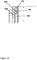
- Figure 12 and 13th show a construction container that includes aspects of the invention.
- the container is designed for a construction volume of approx. 2000l.
- the bulk weight can be up to 4500kg.
- the usual layer thicknesses of 300 ⁇ m are to be delivered with the building platform. The positioning uncertainty should be less than +/- 30 ⁇ m for reliable construction.
- the sequence of a layer infeed is structured as follows. First, starting from the position of the last selectively solidified layer, the building platform is lowered by an amount that is significantly greater than the desired layer thickness. Only then is the construction platform brought to the desired position. This is one layer thickness lower than the last layer that has already been applied and solidified.
- the upward movement of the construction platform must then take place in the predetermined position.
- the travel path should at least preload the device to such an extent that stable conditions are achieved.
- the weight force which constantly increases during the construction process, is less of a problem than the forces caused by the friction of the bed.
- These forces not only increase as does the weight, but also have an unpredictable character due to the settling of the bed and the well-known stick-slip effect. Therefore, the positioning uncertainty increases sharply due to these forces.
- the device according to Figure 12 has 2 solid walls (400). These are made of solid aluminum plates with cutouts on the outer side to reduce weight. The inner surfaces of the walls of this construction container have smooth, milled surfaces.
- the building platform (102) is designed to be heavily ribbed due to the high weight forces.
- the drive engagement takes place on the short sides.
- the long sides are equipped with a seal. It is constructed in two parts. There is a spring element and a seal that can slide easily on the walls of the building container to set a uniform contact pressure and thus for a secure seal.
- the spring element is a cord with a rectangular cross-section made of silicone foam.
- the seal is a felt cord with a rectangular cross-section.
- the building platform rests in the building container. This ensures that the construction container can be removed from the machine when the drive interventions are disengaged.
- the short sides are firmly connected to the flexible container wall (402).
- the flexible wall (402) in this building container is made of an aluminum link chain (1202). This consists of panels with a width of 20mm, which are connected to each other with rubber piping.
- the short side wall has a rigid wall (400) inside.
- This is designed as a welded frame made of rectangular tubular profiles. These profiles carry plastic rails (900) on the inside of the building container. These minimize friction.
- this wall carries a pulley (700).
- the aluminum link chain (1202) is guided over this.
- weights (1300) are attached to the aluminum link chain (1202). These ensure a taut chain when traveling upwards.
- the drive interventions are guided around this external link chain. This makes them easy to contact through the 3D printing device.
- the sealing effect between the aluminum link chain and the rigid wall (400) on the long side of the building container is again achieved using a felt cord.
- the upper edge of the construction container is equipped with profiles in the area of the pulley that make the container interior rectangular. The friction that occurs here can be neglected, since the bed pressure is still very low in this position.
- the long and short walls form a frame that, together with the building platform, represents a container. This is stiffened by a floor construction (1201). Skids are also attached to the underside of this so that the container can be moved with a roller transport system.
- the building container is clad with additional metal sheets (1200) to seal it off against contamination from the outside.
Landscapes
- Engineering & Computer Science (AREA)
- Chemical & Material Sciences (AREA)
- Materials Engineering (AREA)
- Manufacturing & Machinery (AREA)
- Mechanical Engineering (AREA)
- Optics & Photonics (AREA)
- Physics & Mathematics (AREA)
- Ceramic Engineering (AREA)
- Civil Engineering (AREA)
- Composite Materials (AREA)
- Structural Engineering (AREA)
- Plasma & Fusion (AREA)
- Health & Medical Sciences (AREA)
- Toxicology (AREA)
Description
- Die Erfindung betrifft eine Vorrichtung sowie deren Verwendung in einem Verfahren zum Herstellen dreidimensionaler Modelle.
- In der europäischen Patentschrift
EP 0 431 924 B1 wird ein Verfahren zur Herstellung dreidimensionaler Objekte aus Computerdaten beschrieben. Dabei wird ein Partikelmaterial in einer dünnen Schicht auf eine Plattform aufgetragen und dieses selektiv mittels eines Druckkopfes mit einem Bindermaterial bedruckt. Der mit dem Binder bedruckte Partikelbereich verklebt und verfestigt sich unter dem Einfluss des Binders und gegebenenfalls eines zusätzlichen Härters. Anschließend wir die Plattform um eine Schichtdicke in einen Bauzylinder abgesenkt und mit einer neuen Schicht Partikelmaterial versehen, die ebenfalls, wie oben beschrieben, bedruckt wird. Diese Schritte werden wiederholt, bis eine gewisse, erwünschte Höhe des Objektes erreicht ist. Aus den bedruckten und verfestigten Bereichen entsteht so ein dreidimensionales Objekt. - Dieses aus verfestigtem Partikelmaterial hergestellte Objekt ist nach seiner Fertigstellung in losem Partikelmaterial eingebettet und wird anschließend davon befreit. Dies erfolgt beispielsweise mittels eines Saugers. Übrig bleiben danach die gewünschten Objekte, die dann von Pulveranhaftungen z.B. durch händisches Abbürsten befreit werden.
- Das 3D-Drucken auf Basis pulverförmiger Werkstoffe und Eintrag flüssiger Binder ist unter den Schichtbautechniken das schnellste Verfahren.
Mit diesem Verfahren lassen sich verschiedene Partikelmaterialien, dazu zählen - nicht erschöpfend - natürliche biologische Rohstoffe, polymere Kunststoffe, Metalle, Keramiken und Sande, verarbeiten. - Die in derartigen Verfahren verwendeten Maschinen enthalten oft einen Wechselbehälter, der in die 3D-Druckmaschine ein- und ausgefahren werden kann, um so die Maschinenlaufzeiten zu erhöhen. Der Wechselbehälter kann aus der Maschine ausgefahren werden, um die Bauteile von nicht verfestigtem Material zu befreien, d.h. zu entpacken. Ein anderer Wechselbehälter kann dann sofort in die Maschine eingefahren werden und es kann sofort weitergedruckt werden, sodass es zu keinen unnötigen unproduktiven Standzeiten der Maschinen kommt. Derartige Wechselbehälter weisen eine Bauplattform auf, auf die das Partikelmaterial aufgetragen wird. Diese Bauplattform ist in der Regel höhenverstellbar und wird während des 3D-Druckprozesses nach unten verfahren bis der Druckprozess abgeschlossen ist Durch das Verfahren und die Positionierung der Bauplattform wird die gewünschte Schichtstärke eingestellt.
- Die genaue Positionierung der Bauplattform ist hierbei sehr wichtig und entscheidend für die Herstellung von formgenauen Bauteilen. Dabei ist nicht nur die Positionierung der Baupattform am Antriebsangriffspunkt wichtig, sondern eine gleichmäßige Positionierung aller Punkte der Bauplattform hat Einfluss auf die Baugenauigkeit. Mögliche Deformationen der Bauplattform stellen ein Problem für ein genaues und präzises Herstellen der Bauteile dar.
- Eine genaue und gleichmäßige Positionierung stellt bei großen Maschinen aber eine große Schwierigkeit dar. Durch die großen Abmessungen entstehen hohe Biegemomente, die die Bauplattform deformieren. Wird die Bauplattform entsprechend ausgesteift, sind allerdings wiederum hohe Massen exakt zu positionieren. Die verschiedenen Aspekte dieser Probleme reduzieren die erreichbare Genauigkeit der Vorrichtung oder stehen einem akzeptablen Kostenrahmen entgegen.
- Die Kräfte und die damit resultierenden Biegemomente werden durch unterschiedliche Einflüsse erzeugt. Zum einen wirkt die im Bauprozess wachsende Pulverschüttung als wachsende Flächenlast. Zum zweiten drückt die entstehende Schüttung auf die Wände des Baubehälters. Hier ergeben sich Reaktionskräfte, die wiederum auf die Bauplattform wirken. Zusätzlich werden Kräfte durch die Dichtung verursacht, die die bewegte Bauplattform gegen die stehenden Seitenwände abdichtet.
- Für die wachsende Flächenlast werden Lösungen in Patentschriften beschrieben. So offenbart beispielsweise
DE 10 2010 013 733 A1 eine Vorrichtung bei der der Baubehälter als unbewegter Arbeitstisch ausgeführt wird. Die Vorrichtungen zum Erzeugen einer neuen Pulverschicht und zum selektiven Verfestigen sind dabei in der Baurichtung der Vorrichtung verschieblich. Die beschriebene Bauplattform kann konstruktiv einfach den Steifigkeitsanforderungen angepasst werden. Die Vorrichtung ist allerdings durch ihre wandlose Ausführung im verwendbaren Materialspektrum beschränkt. - Die Dichtungskräfte können durch konstruktive Maßnahmen beeinflusst werden. So ist es eine Möglichkeit, einen Baubehälter zu verwenden, der mit einer Filzdichtung ausgestattet ist, um die Reibung der Dichtung zu senken. Ebenso können ausblasbare Dichtungen verwendet werden, um die Anpresskraft so niedrig wie möglich zu halten.
- Die seitliche Reibwirkung der Schüttung gegen die Seitenwände ist bei Baubehältern oder Wechselbehältern nach dem Stand der Technik ein ungelöstes Problem. Die Wirkungen der daraus resultierenden Kräfte werden nach dem Stand der Technik durch konstruktive Maßnahmen gemildert. Dabei werden Baubehälter verwendet, deren Antriebspunkte zur Minimierung der Durchbiegung gewählt wurden. Hier können Flächenlasten durch das Materialgewicht und Reibungswirkung und Linienlasten durch die Dichtung berücksichtigt werden. Trotz dieser Optimierung ergeben sich immer noch massivere Konstruktionen als zum eigentlichen Abstützen der Gewichtskraft notwendig wären.
- Eine ebenso konstruktive Maßnahme zur Reduzierung der Kraftwirkungen ist die Verkürzung des Kraftflusses in der Vorrichtung. Dazu wird z.B. in
DE 100 47 614 C2 ein Durchgriff durch die Baubehälterwand realisiert. Dieser Durchgriff wird durch ein Band oder einen Vorhang gegen Durchfließen des Partikelmaterials abgedichtet. Für schwere Schüttungen sind Vorrichtungen entsprechend groß auszuführen. Die Lösung mit Vorhang ist nur für leichtes Partikelmaterial geeignet, das kaum Druck auf die Wand ausübt.WO 90/03893 A1 - Insbesondere entsteht beim Verfahren der Bauplattform seitlich eine Reibung, die dazu führt, dass es innerhalb des partikulären Auftragsmaterials zu Spannungen kommt. Durch diese Spannungen kann es zu Bewegungen im partikulären Auftragsmaterial kommen und dadurch werden die vorbestimmten und aufgrund der CAD Daten gedruckten Bauteilpunkte verschoben. Letztendlich weichen dann die in dem Bauteil vorhandenen Raumpunkte von den CAD Daten ab und das gedruckte Bauteil entspricht nicht mehr 1:1 dem Datensatz. Das gedruckte Bauteil ist somit ungenau. Diese Ungenauigkeit beruht zu einem großen Teil auf der Reibungsproblematik.
- Allerdings wurde bisher dieses Problem in der Literatur und dem Stand der Technik nicht als Problem und Ursache für ungenau hergestellte Bauteile erkannt. Somit wurde dieses Problem auch weder in einem zufriedenstellenden Maße adressiert noch gibt es herzu Lösungsansätze in der Literatur oder dem Stand der Technik.
- Es ist daher eine Aufgabe der Erfindung eine Vorrichtung bereitzustellen, die die oben beschriebenen Probleme löst und insbesondere einen Wechselbehälter bereitstellt, mit dem qualitativ hochwertige Bauteile mit hoher Abbildungsgenauigkeit herstellbar sind und insbesondere Wechselbehälter mit verminderter Reibungsproblematik zur Verfügung stellt oder eine Lösung, die zumindest die Nachteile des Standes der Technik vermeidet oder zumindest vermindern hilft.
- Die Erfindung betrifft einen Baubehälter gemäß vorliegendem Anspruch 1, der die Herstellung von hochwertigen Bauteilen ermöglicht, und der insbesondere eine verminderte Reibungsproblematik aufweist. Dies wird erreicht durch zwei, vorzugsweise drei, bevorzugt vier, seitlich angeordnete bewegliche Seitenwände, die sich mit mit der selben Geschwindigkeit bewegen lassen wie die Bauplattform in dem erfindungsgemäße Baubehälter.
- Insbesondere betrifft die Erfindung einen Baubehälter für eine Vorrichtung zum Herstellen dreidimensionaler Modelle mittels Schichtaufbautechnik, der aufweist ein Baufeld auf einer Bauplattform, die in dem Baubehälter höhenverstellbar und vorzugsweise aus ihm entnehmbar ist, mindestens zwei Seitenwände, die so ausgestaltet sind, dass beim Verfahren der Bauplattform die Gleitreibung zwischen den aufgebauten Schichten und den Seitenwänden vermindert oder im Wesentlichen vermieden wird, wobei die Bauplattform und die mindestens zwei Seitenwände mit gleicher Geschwindigkeit verfahren werden, wobei im Baubehälter mindestens eine seitlich angeordnete biegeweiche Wand (402) durch mindestens eine seitlich angeordnete biegesteife Wand (400) abgestützt ist, wobei diese Anordnung der Wände mindestens an zwei Seiten des Baubehälters vorhanden ist und die biegeweiche Wand (402) auf mindestens einer Umlenkrolle (700) umgelenkt wird.
- In einem weiteren Aspekt betrifft die Erfindung ein 3D-Druckverfahren, in dem der erfindungsgemäße Baubehälter (Wechselbehälter) einsetzbar ist.
- Im Folgenden werden einige Begriffe der Erfindung näher erläutert.
- Im Sinne der Erfindung sind "3D-Druckverfahren" alle aus dem Stand der Technik bekannten Verfahren, die den Aufbau von Bauteilen in dreidimensionalen Formen ermöglichen und mit den beschriebenen Verfahrenskomponenten und Vorrichtungen kompatibel sind. Insbesondere sind dies Pulver-basierte Verfahren, wie beispielsweise SLS (Selective Laser Sintering).
- "Selektiver Binderauftrag" oder "Selektiver Bindersystemauftrag" kann im Sinne der Erfindung nach jedem Partikelmaterialauftrag erfolgen oder je nach den Erfordernissen des Formkörpers und zur Optimierung der Formkörperherstellung auch unregelmäßig erfolgen, d.h. nicht linear und parallel nach jedem Partikelmaterialauftrag. "Selektiver Binderauftrag" oder "Selektiver Bindersystemauftrag" kann somit individuell und im Verlauf der Formkörperherstellung eingestellt werden.
- "Formkörper" oder "Bauteil" im Sinne der Erfindung sind alles mittels des erfindungsgemäßen Verfahrens oder/und der erfindungsgemäßen Vorrichtung hergestellte dreidimensionale Objekte, die eine Formfestigkeit aufweisen.
- Als "Vorrichtung" zum Durchführen des erfindungsgemäßen Verfahrens kann jede bekannte 3D-Druckvorrichtung verwendet werden, die die erforderlichen Bauteile beinhaltet. Übliche Komponenten beinhalten Beschichter, Baufeld, Mittel zum Verfahren des Baufeldes oder anderer Bauteile, Dosiervorrichtung und Wärmemittel und andere dem Fachmann bekannte Bauteile, die deshalb hier nicht näher ausgeführt werden.
- Als "Partikelmaterialien" können alle für den Pulver-basierten 3D Druck bekannten Materialien verwendet werden, insbesondere Sande, Keramikpulver, Metallpulver, Kunststoffe, Holzpartikel, Faserwerkstoffe, Cellulosen oder/und Lactosepulver. Das Partikelmaterial ist vorzugsweise ein trocken frei fließendes und ein kohäsives schnittfestes Pulver.
- "Bauraum" ist der geometrische Ort in dem die Partikelmaterialschüttung während des Bauprozesses durch wiederholtes Beschichten mit Partikelmaterial wächst. Im Allgemeinen wird der Bauraum durch einen Boden, die Bauplattform, durch Wände und eine offene Deckfläche, die Bauebene, begrenzt.
- Ein "Baubehälter" oder insbesondere "Wechselbehälter" im Sinn der Erfindung realisiert einen Bauraum. Er weist demnach einen Boden, Wände und eine offene Zugangsfläche, die Bauebene, auf. Der Baubehälter weist immer Teile auf, die sich relativ zum Gestell der 3D-Druckvorrichtung nicht bewegen. Austauschbare Baubehälter ermöglichen es die Maschine quasi ständig zu betreiben. Während die Teile eines ersten Bauvorganges ausgepackt werden können innerhalb der Maschine in einem zweiten Baubehälter bereit neue Teile gedruckt werden.
- Die "Druck- und Beschichterebene" ist die Abstraktion des Ortes des momentan ablaufenden Bauprozesses. Da konstruktiv die Dosiereinheit und der Beschichter auf einer Verfahreinheit mit gemeinsamen Komponenten auf nahezu einer Höhe in der Vorrichtung bewegt werden, wird in dieser Beschreibung die "Druck- und Beschichterebene" als in der Oberkante einer neu aufgebrachten Schicht liegend betrachtet.
- Die "Bauplattform" bewegt sich relativ zur Druck- und Beschichterebene. Diese Relativbewegung findet während des Bauprozesses in unterbrochenen Bewegungen in Schichtstärke statt. Sie definiert die Schichtstärke.
- "Behälterwand" oder "Wand" oder "Seitenwand" bezeichnet eine Barriere für das Partikelmaterial. Das Partikelmaterial kann nicht von einer Seite auf die andere Seite der Wand gelangen. Wände im Sinne der Erfindung können biegeweich oder biegesteif ausgeführt sein. Dabei sind die Durchbiegungen für das Kriterium "Biegesteif" gering bezogen auf die Werkstücktoleranzen bei einem gegebenen Materialsystem.
- Eine "Gleitpaarung" im Sinn der Erfindung ist ein Werkstoffkontakt dessen Reibungskoeffizient deutlich unter dem zweier gleicher Werkstoffe in Kontakt oder des Kontaktes zwischen Partikelmaterial und einem Wandwerkstoff liegt.
- Eine "Dichtung" bezeichnet jeweils konstruktive Elemente die einen Durchtritt des Partikelmaterials durch Kontaktstellen zwischen relativ zueinander bewegten Wänden oder Wänden und einer Bauplattform verhindert.
- Im Weiteren wird die Erfindung genauer dargestellt sowie deren bevorzugte Ausführungsformen.
- Die Erfindung betrifft einen Baubehälter, insbesondere einen Wechselbehälter, für eine Vorrichtung zum Herstellen dreidimensionaler Modelle mittels Schichtaufbautechnik, der aufweist ein Baufeld auf einer Bauplattform, die in dem Baubehälter höhenverstellbar und vorzugsweise aus ihm entnehmbar ist,
mindestens zwei Seitenwände, die so ausgestaltet sind, dass beim Verfahren der Bauplattform die Gleitreibung zwischen den aufgebauten Schichten und den Seitenwänden vermindert oder im Wesentlichen vermieden wird, wobei die Bauplattform und die mindestens zwei Seitenwände mit gleicher Geschwindigkeit verfahren werden, dadurch gekennzeichnet, dass im Baubehälter mindestens eine seitlich angeordnete biegeweiche Wand (402) durch mindestens eine seitlich angeordnete biegesteife Wand (400) abgestützt ist, wobei diese Anordnung der Wände mindestens an zwei Seiten des Baubehälters vorhanden ist und die biegeweiche Wand (402) auf mindestens einer Umlenkrolle (700) umgelenkt wird. - In einem Aspekt ist die Erfindung die direkte Reduktion der Kräfte zwischen Partikelmaterial und Seitenwand im Baubehälter. Dazu können konstruktiv unterschiedliche Maßnahmen hilfreich sein. Die Vermeidung der Relativbewegungen bewirkt außerdem zur Gravitation keine zusätzlichen Kraftwirkungen im Pulver und kann somit unerwünschtes Setzen des Pulverkuchens vermeiden.
- Dadurch kann vorteilhafter Weise erreicht werden, dass es zu keinen oder weniger Kräften kommt, die sich negativ auf die Stabilität der aufgetragenen und aufgebrachten Schichten auswirken, und somit die Abbildungsgenauigkeit in den gedruckten Bauteilen erhöht werden kann.
- Vorzugsweise sind mindestens 3 oder 4 Seitenwände in eine Richtung biegeweich ausgeführt. Weiterhin bevorzugt ist, dass mindestens eine, vorzugsweise 2, 3 oder 4, Seitenwände eine segmentierte oder/und metallische Wand ist und in eine Richtung biegeweich ausgeführt ist.
- In einer weiteren bevorzugten Ausführungsform ist der Baubehälter dadurch gekennzeichnet, dass eine Metall/Kunststoffgleitpaarung zur Reduktion der Reibungswirkung aufweist. Weiterhin bevorzugt weist der Baubehälter ein abgestütztes in alle Richtungen biegeweiches Band als Seitenwand auf.
- In weiteren bevorzugten Ausführungsformen betrifft die Offenbarung insbesondere eine Vorrichtung zum Herstellen eines Bauteils (3D-Formkörper), wobei (a) in einem ersten Schritt mittels Pulverbeschichter (101) eine Partikelschicht auf eine Bauplattform (102) aufgebracht wird, (b) in einem zweiten Schritt mittels Binder-Dosiervorrichtung (100) ein Binder (400) selektiv aufgetragen wird, (c) in einem weiteren Schritt die aufgebrachte Schicht oder Schichten mittels Wärmequelle (600) einer Wärmebehandlung unterzogen werden, (d) die Bauplattform (102) abgesenkt wird oder der Pulverbeschichter (101) und gegebenenfalls weitere Vorrichtungsbauteile um eine Schichtdicke angehoben wird, Schritte (a) bis (d) wiederholt werden bis das Bauteil aufgebaut ist.
- Der Natur des Partikelmaterials (300) gemäß stellt die dadurch entstehende Schüttung eine Belastung für den Baubehälter und die Bauplattform dar. Dabei entstehen ähnlich hydrostatischen Drücken charakteristische Druckprofile (201) auf die Wandungen (200). Lineare Verläufe des Drucks über die Bauhöhe treten im statischen Fall nicht auf. Wird das Pulver aber durch mechanische Vibrationen angeregt bilden sich nahezu hydrostatische also lineare Druckverläufe aus.
- Die durch das Pulver verursachten Druckbelastungen auf die Behälterwand stellen Kräfte normal zur Wandung dar. Sobald eine Bewegung senkrecht zur Kraftrichtung auftritt entstehen Reaktionskräfte über die Reibung.
- Dabei schließt sich der Kraftfluss meist über weite Teile der Vorrichtung.
Figur 3 zeigt ein Schnittbild durch eine mögliche Vorrichtung. Die Kraft entsteht zwischen den Behälterwänden (200) und Schüttung (300). Durch die Schüttung wird die Kraft in den Behälterboden (102) geleitet. Weiter geht der Verlauf durch die Antriebspunkte (301) über die Kupplung (302) auf den Z-Achstrieb der meist als Hubspindel (303) ausgeführt wird. Dieser stützt sich meist über eine Lagerung (304) am Hauptgestellt der Vorrichtung ab. Über die Baubehälter-Halteriegel, die wiederum am Gestell der Vorrichtung angebracht sind, und die Baubehälterwand schließt sich der Kraftfluss. - Je nach konstruktiver Ausführung treten durch den Kraftfluss Biegungen und Längungen auf, die die Präzision der Vorrichtung beeinflussen. Erfindungsgemäß, wird nicht vornehmlich konstruktiv der Kraftfluss verkürzt und die Vorrichtung beanspruchungsgerecht ausgelegt, sondern die Kraftwirkung der Reibung bei Relativbewegung minimiert.
- Die Reibung durch den direkten Kontakt von Wand und Partikelmaterial könnte durch eine Beschichtung minimiert werden. Abrasive Partikelmaterialien würden diese Beschichtung allerdings bei Relativbewegung schnell unwirksam machen. Dabei wirken selbst Kunststoffpulver abrasiv.
- Ein Ansatz zur Vermeidung von Relativbewegungen ist eine Vorrichtung die die oben genannten Schritte zur Erstellung von Modellen im Inneren eines Baubehälters ausführt. Während des Bauprozesses wandert die Beschichtungs- und Druckeinheit (100, 101) aus dem Baubehälter. In der oberen Endlage kann der Baubehälter dann getauscht werden. Eine solche Vorrichtung weist den Nachteil auf, dass die Teile Beschichtungseinheit (101) und Dosiereinheit (100) endliche Abmessungen aufweisen und nicht nur den Arbeitsbereich überdecken. Damit würde sich die Vorrichtung insgesamt unnötig vergrößern. Zudem müssen die Beschleunigungsrampen der Komponenten berücksichtigt werden, da deren Funktion nur bei linearer Bewegung endwandfrei ausgeführt wird.
- Diese technisch ungünstige Konstruktion kann ebenso erfindungsgemäß auf zwei relativ zur Schüttung stehende Wände reduziert werden.
Figur 6 (nicht Teil der Erfindung) zeigt beispielhaft die Baubehälterkonstruktion einer solchen Vorrichtung. - Dazu wird ein U-förmiger Körper bestehend aus zwei biegesteifen Wänden (400) und der Bauplattform (102) gebildet. Dieser Körper wird zwischen zwei biegesteifen, gestellfesten Wänden (400) bewegt, die zu den Wänden des U-förmigen Körpers senkrecht angeordnet sind. An den Stirnflächen des Körpers sind jeweils Dichtungen (401) angebracht, die ein Ausfließen von Partikelmaterial verhindern. Die Ebene (701) der neu zu bildenden Schichten liegt bei dieser Vorrichtung immer an der Oberkante der gestellfesten Wände.
- Bei dieser Vorrichtung können der Beschichter und die Dosiereinheit durch den entstehenden "Schacht" fahren und beschleunigt werden. Die übrigen Funktionsmerkmale gleichen denen einer Vorrichtung mit konventionellem Baubehälter.
- Die Kräfte auf die bewegten Wände führen bei dieser Konstruktion zu keinerlei Reibungswirkung. Die Kräfte auf die stehenden Wände erzeugen die gleichen Reibungskräfte, die auch bei konventioneller Konstruktion entstehen. Bei erfindungsgemäßer Anordnung der Gesamtkonstruktion können allerdings die Kräfte und die besonders schädlichen Biegemomente auf die Bauplattform erheblich reduziert werden.
- Störend bei einer solchen Vorrichtung sind die Einschränkungen im Verfahrbereich von Dosiereinheit und Beschichter. Um diese zur vermeiden müssen die Wände bei Abwärtsbewegung der Bauplattform gedanklich in Dosier- und Beschichterebene entstehen.
- Eine solche Wirkung kann in erster Näherung durch die Verwendung einer Rolle (700) mit einer biegeweichen Wand (402) erreicht werden. Dabei wird die Wand von der Rolle durch die Bewegung der Bauplattform (102) abgerollt.
- Eine biegeweiche Wand (402) wird dabei durch den Druck der Schüttung verformt. Um den Bauprozess nicht zu gefährden, müssen dabei die Verformungen durch konstruktive Maßnahmen gering gehalten werden. Erfindungsgemäß wird die biegeweiche Wand (402) durch eine biegesteife Wand (400) abgestützt. Der Reibungskoeffizient zwischen den kontaktierenden Materialien muss dabei erfindungsgemäß geringer sein als zwischen der biegesteifen Wand und dem Partikelmaterial.
- Typische Werkstoffpaarungen sind Metall-/Kunststoffkontakte oder Paarungen als verschiedenen Metallen. Dabei kann beispielsweise die biegeweiche Wand (402) aus Metall als dünnes Blechband ausgeführt werden. Die biegesteife Wand (400) ist bei dieser Ausführung mit Kunststoff oder Messingleisten (900) belegt. Ebenso kann die Wand als Kunststoffband ausgeführt werden das auf einer Metallfläche abgleitet.
- Das Band kann bevorzugt auch aus mehreren Materialien bestehen. Z.B. kann ein Kontaktmaterial zum Partikelmaterial besonders wiederstandfähig ausgeführt werden. Die Festigkeit kann über ein spezielles Zugband dargestellt werden. Auf der Rückseite kann eine Gleitbeschichtung aufgebracht sein.
- Ebenso kann eine biegeweiche Wand (402) auch auf Rollen (901) gleiten. Dafür eignen sich pulverdichte Gliederketten. Gegenüber von Gleitpaarungen können die Reibungskräfte weiter reduziert werden. Konstruktiv können solche Rollen aber nur bei größeren Vorrichtungen sinnvoll zum Einsatz kommen.
- Die oben genannte Vorrichtung mit zwei relativ zur Schüttung nicht bewegten Wänden kann auch mit vier nicht bewegten Wänden ausgeführt werden. Eine solche Vorrichtung würde die Reibungskräfte wie die oben genannte Vorrichtung mit 4 biegesteifen stehenden Wänden gemäß der Erfindung stark reduzieren.
- Weitere bevorzugte Aspekte sowie beispielhaft eine bevorzugte Ausführungsform und Vorteile der Erfindung werden im Folgenden weiter ausgeführt.
-
Figur 12 und13 zeigen einen Baubehälter der erfindungsgemäße Aspekte beinhaltet. - Der Behälter ist für ein Bauvolumen von ca. 2000l ausgelegt. Bei der Verwendung von Gießereiformstoffen wie Sand oder Chromerz als Partikelmaterial kann das Schüttungsgewicht dabei bis 4500kg betragen. Während des Aufbauprozesses sind dabei als übliche Schichtstärken 300µm mit der Bauplattform zuzustellen. Die Positionierunsicherheit sollte dabei für ein prozesssicheres Bauen kleiner als +/- 30µm sein.
- Um die statischen Verformungen klein zu halten und die Wirkung von Losen zu minimieren gliedert sich der Ablauf einer Schichtzustellung wie folgt. Zuerst wird, ausgehend von der Position der zuletzt selektiv verfestigten Schicht, die Bauplattform um einen Betrag, der wesentlich größer ist als die angestrebte Schichtstärke, abgesenkt. Erst danach wird die Bauplattform auf die gewünschte Position gebracht. Diese liegt um eine Schichtstärke weiter unten als die bereits ausgebrachte und verfestigte letzte Schicht.
- Während des Positionierens werden verschiedene Komponenten wie das Maschinengestell oder die Bauplattform durch die wirkenden Kräfte deformiert. Dabei kann die Bauplattform, wenn sie durch die Pulverschüttung noch nicht ausreichend belastet ist, im Baubehälter hängen bleiben und der Positionierbewegung erst folgen wenn alle Lose überwunden sind und die Deformationsreaktionskräfte der Komponenten die Reibungskräfte überwinden. Diese Wegstrecke muss beim Absenken mindestens vorgesehen werden.
- Die Aufwärtsbewegung der Bauplattform muss dann auf die vorbestimmte Position erfolgen. Auch hier sollte der Verfahrweg mindestens die Vorrichtung soweit vorspannen, dass stabile Verhältnisse erreicht werden.
- Für das sichere Einhalten dieser Positionierunsicherheit ist weniger die während des Bauprozess ständig anwachsende Gewichtskraft problematisch als die Kräfte durch die Reibung der Schüttung. Diese Kräfte wachsen nicht nur ebenso wie die Gewichtskraft, sondern weisen durch Setzungen der Schüttung und den bekannten Stick-Slip-Effekt einen unvorhersehbaren Charakter auf. Deshalb steigt die Positionierunsicherheit durch diese Kräfte stark an.
- Die Vorrichtung nach
Figur 12 weist 2 feste Wände (400) auf. Diese sind aus massiven Aluminiumplatten, die an der äußeren Seite Ausfräsungen zur Gewichtsreduktion aufweisen. Die Innenflächen der Wände dieses Baubehälters haben glatte, gefräste Oberflächen. - Die Bauplattform (102) ist auf Grund der hohen Gewichtskräfte stark verrippt ausgeführt. An den kurzen Seiten erfolgt jeweils der Antriebseingriff. Die langen Seiten sind mit einer Dichtung ausgestattet. Sie ist zweiteilig aufgebaut. Zur Einstellung eines gleichmäßigen Anpressdrucks und damit zur sicheren Abdichtung gibt es ein Federelement und eine Dichtung, die gut auf den Wänden des Baubehälters gleiten kann. Das Federelement ist eine Schnur mit rechteckigem Querschnitt aus Silikonschaum. Die Dichtung ist eine Filzschnur mit rechteckigem Querschnitt.
- In der unteren Endlage liegt die Bauplattform im Baubehälter auf. Damit ist gewährleistet, dass der Baubehälter aus der Maschine genommen werden kann, wenn die Antriebseingriffe ausgekuppelt sind.
- Die kurzen Seiten sind mit der biegeweichen Behälterwand (402) fest verbunden.
- Die biegeweiche Wand (402) ist bei diesem Baubehälter aus einer Aluminiumgliederkette (1202). Diese besteht aus Platten mit 20mm Breite, die mit Gummikedern untereinander verbunden sind.
- Die kurze Seitenwand weist im inneren eine biegesteife Wand (400) auf. Diese ist als geschweißtes Gestell aus rechteckigen Rohrprofilen ausgeführt. Diese Profile tragen Kunststoffschienen (900) auf der Baubehälterinnenseite. Diese Minimieren die Reibung.
- Am oberen Ende trägt diese Wand eine Umlenkrolle (700). Über diese wird die Aluminiumgliederkette (1202) geführt. Auf der der Behälterinnerseite abgewandten Seite der Wand sind Gewichte (1300) an der Aluminiumgliederkette (1202) angebracht. Diese sorgen bei der Aufwärtsfahrt für ein straffe Kette.
- Die Antriebseingriffe werden um diese außen liegende Gliederkette herumgeführt. Damit sind sie leicht durch die 3D-Druckvorrichtung zu kontaktieren.
- Die Dichtwirkung zwischen der Aluminiumgliederkette und der biegesteifen Wand (400) an der langen Seite des Baubehälters wird wieder über eine Filzschnur erreicht. Dabei ist an der Platte der langen Seite eine Ausfräsung vorhanden, die die Dichtschnur führt.
- Die Oberkante des Baubehälters ist im Bereich der Umlenkrolle mit Profilen ausgestattet, die den Behälterinnenraum rechteckig ausgestalten. Die hier auftretende Reibung kann vernachlässigt werden, da in dieser Lage der Schüttungsdruck noch sehr klein ist.
- Die langen und kurzen Wände bilden einen Rahmen, der mit der Bauplattform einen Behälter darstellt. Dieser wird durch eine Bodenkonstruktion (1201) ausgesteift. An dieser sind zusätzlich an der Unterseite Kufen angebracht, um den Behälter mit einem Rollentransportsystem bewegen zu können.
- An den kurzen Wänden sind Vorrichtungen für die Verbindung von Behälter und 3D-Vorrichtung vorhanden. Diese können nach Einfahren des Behälters verriegelt werden. Dabei wird der Behälter positioniert und arretiert.
- Zur Abdichtung gegen Verschmutzungen von außen ist der Baubehälter mit zusätzlichen Blechen (1200) verkleidet.
-
-
Figur 1 : Schematische Darstellung der Komponenten eines pulverbasierten 3D-Druckers als geschnittener Schrägriss. -
Figur 2 : Schematische Darstellung der Kraftwirkung der Pulverschüttung. -
Figur 3 : Kraftfluss in einer Vorrichtung des Standes der Technik als Schema -
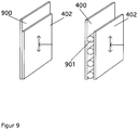
Figur 4 : Darstellung einer biegesteifen und einer biegeweichen Behälterwand -
Figur 5 (nicht Teil der Erfindung): Vorrichtung mit einem Baubehälter mit vier zur Schüttung nicht bewegten biegesteifen Wänden -
Figur 6 (nicht Teil der Erfindung): Konstruktion eines Baubehälters mit zwei biegesteifen relativ zur Schüttung nicht bewegten Wänden und zwei biegesteifen zur Schüttung relativ bewegten Wänden. -
Figur 7 : Schema der Vermeidung von Wänden im Verfahrbereich von Dosiereinheit und Beschichter durch biegeweiche Wände -
Figur 8 : Schema der Ableitung der Druckkräfte über hintereinander geschaltete Wandungen -
Figur 9 (nicht Teil der Erfindung): Minimierung der Kräfte durch den Einsatz einer Gleitpaarung
Minimierung der Kräfte durch den Einsatz von Rollen -
Figur 10 : Baubehälter mit zwei relativ zur Schüttung nicht bewegten und biegeweichen Wänden -
Figur 11 : Baubehälter mit vier relativ zur Schüttung nicht bewegten und biegenweichen Wänden -
Figur 12 (nicht Teil der Erfindung): Schnittdarstellung eines Baubehälters mit biegeweichen relativ zur Schüttung nicht bewegten Wänden -
Figur 13 : Konstruktive Details eines Baubehälters mit biegeweichen relativ zur Schüttung nicht bewegten Wänden -
- 100
- Binder-Dosiervorrichtung
- 101
- Pulverbeschichter
- 102
- Bauplattform
- 103
- Bauteil (3D Formteil)
- 104
- Baufeldberandung
- 107
- Pulverschichten
- 200
- Wand
- 201
- Kraftverlauf
- 300
- Partikelmaterial
- 301
- Antriebspunkt
- 302
- Kupplung
- 303
- Hubspindel
- 304
- Lagerung
- 400
- Biegesteife Wand
- 401
- (Filz-)Dichtung
- 402
- Biegeweiche Wand
- 500
- Verfahreinheit
- 501
- Führungen
- 700
- Umlenkrolle
- 701
- Druck- und Beschichterebene
- 800
- Freie Durchbiegung
- 900
- Gleitfläche
- 901
- Rollen
- 1200
- Gehäuse
- 1201
- Boden
- 1202
- Aluminiumgliederkette
- 1300
- Gegengewicht
Claims (6)
- Baubehälter für eine Vorrichtung zum Herstellen dreidimensionaler Modelle mittels Schichtaufbautechnik, der aufweist ein Baufeld auf einer Bauplattform (102), die in dem Baubehälter höhenverstellbar und vorzugsweise aus ihm entnehmbar ist, mindestens zwei Seitenwände, die so ausgestaltet sind, dass beim Verfahren der Bauplattform die Gleitreibung zwischen den aufgebauten Schichten und den Seitenwänden vermindert oder im Wesentlichen vermieden wird, wobei die Bauplattform und die mindestens zwei Seitenwände mit gleicher Geschwindigkeit verfahren werden, im Baubehälter mindestens eine seitlich angeordnete biegeweiche Wand (402) durch mindestens eine seitlich angeordnete biegesteife Wand (400) abgestützt ist, wobei diese Anordnung der Wände mindestens an zwei Seiten des Baubehälters vorhanden ist und die biegeweiche Wand (402) auf mindestens einer Umlenkrolle (700) umgelenkt wird.
- Baubehälter nach Anspruch 1, dadurch gekennzeichnet, dass mindestens 3 oder 4 Seitenwände in eine Richtung biegeweich ausgeführt sind.
- Baubehälter nach einem der vorhergehenden Ansprüche, dadurch gekennzeichnet, dass mindestens 2, 3 oder 4, Seitenwände ein segmentierte oder/und metallische Wand ist und in eine Richtung biegeweich ausgeführt ist.
- Baubehälter nach einem der vorhergehenden Ansprüche, dadurch gekennzeichnet, dass eine Metall/Kunststoffgleitpaarung zur Reduktion der Reibungswirkung genutzt wird.
- Baubehälter nach einem der vorhergehenden Ansprüche, dadurch gekennzeichnet, dass ein abgestütztes in alle Richtungen biegeweiches Band als Seitenwand verwendet wird, vorzugsweise
dadurch gekennzeichnet, dass ein Band aus mehreren Materialien mit einer Gleitschicht verwendet wird. - Baubehälter nach einem der vorhergehenden Ansprüche, dadurch gekennzeichnet, dass ein endloses Band als Seitenwand verwendet wird.
Priority Applications (1)
| Application Number | Priority Date | Filing Date | Title |
|---|---|---|---|
| PL14823886T PL3077181T3 (pl) | 2013-12-02 | 2014-12-01 | Pojemnik budowlany z przesuwnymi ścianami bocznymi |
Applications Claiming Priority (2)
| Application Number | Priority Date | Filing Date | Title |
|---|---|---|---|
| DE102013018031.7A DE102013018031A1 (de) | 2013-12-02 | 2013-12-02 | Wechselbehälter mit verfahrbarer Seitenwand |
| PCT/DE2014/000609 WO2015081926A1 (de) | 2013-12-02 | 2014-12-01 | Wechselbehälter mit verfahrbarer seitenwand |
Publications (2)
| Publication Number | Publication Date |
|---|---|
| EP3077181A1 EP3077181A1 (de) | 2016-10-12 |
| EP3077181B1 true EP3077181B1 (de) | 2021-04-21 |
Family
ID=52282360
Family Applications (1)
| Application Number | Title | Priority Date | Filing Date |
|---|---|---|---|
| EP14823886.8A Active EP3077181B1 (de) | 2013-12-02 | 2014-12-01 | Baubehälter mit verfahrbaren seitenwänden |
Country Status (8)
| Country | Link |
|---|---|
| US (3) | US10220568B2 (de) |
| EP (1) | EP3077181B1 (de) |
| KR (1) | KR102300993B1 (de) |
| CN (3) | CN114953442A (de) |
| DE (1) | DE102013018031A1 (de) |
| ES (1) | ES2871750T3 (de) |
| PL (1) | PL3077181T3 (de) |
| WO (1) | WO2015081926A1 (de) |
Families Citing this family (53)
| Publication number | Priority date | Publication date | Assignee | Title |
|---|---|---|---|---|
| US10226919B2 (en) | 2007-07-18 | 2019-03-12 | Voxeljet Ag | Articles and structures prepared by three-dimensional printing method |
| DE102007050953A1 (de) | 2007-10-23 | 2009-04-30 | Voxeljet Technology Gmbh | Vorrichtung zum schichtweisen Aufbau von Modellen |
| DE102010006939A1 (de) | 2010-02-04 | 2011-08-04 | Voxeljet Technology GmbH, 86167 | Vorrichtung zum Herstellen dreidimensionaler Modelle |
| DE102010013732A1 (de) | 2010-03-31 | 2011-10-06 | Voxeljet Technology Gmbh | Vorrichtung zum Herstellen dreidimensionaler Modelle |
| DE102010014969A1 (de) | 2010-04-14 | 2011-10-20 | Voxeljet Technology Gmbh | Vorrichtung zum Herstellen dreidimensionaler Modelle |
| DE102010015451A1 (de) | 2010-04-17 | 2011-10-20 | Voxeljet Technology Gmbh | Verfahren und Vorrichtung zum Herstellen dreidimensionaler Objekte |
| DE102010056346A1 (de) | 2010-12-29 | 2012-07-05 | Technische Universität München | Verfahren zum schichtweisen Aufbau von Modellen |
| DE102011007957A1 (de) | 2011-01-05 | 2012-07-05 | Voxeljet Technology Gmbh | Vorrichtung und Verfahren zum Aufbauen eines Schichtenkörpers mit wenigstens einem das Baufeld begrenzenden und hinsichtlich seiner Lage einstellbaren Körper |
| DE102011111498A1 (de) | 2011-08-31 | 2013-02-28 | Voxeljet Technology Gmbh | Vorrichtung zum schichtweisen Aufbau von Modellen |
| DE102012004213A1 (de) | 2012-03-06 | 2013-09-12 | Voxeljet Technology Gmbh | Verfahren und Vorrichtung zum Herstellen dreidimensionaler Modelle |
| DE102012010272A1 (de) | 2012-05-25 | 2013-11-28 | Voxeljet Technology Gmbh | Verfahren zum Herstellen dreidimensionaler Modelle mit speziellen Bauplattformen und Antriebssystemen |
| DE102012012363A1 (de) | 2012-06-22 | 2013-12-24 | Voxeljet Technology Gmbh | Vorrichtung zum Aufbauen eines Schichtenkörpers mit entlang des Austragbehälters bewegbarem Vorrats- oder Befüllbehälter |
| DE102012020000A1 (de) | 2012-10-12 | 2014-04-17 | Voxeljet Ag | 3D-Mehrstufenverfahren |
| DE102013004940A1 (de) | 2012-10-15 | 2014-04-17 | Voxeljet Ag | Verfahren und Vorrichtung zum Herstellen von dreidimensionalen Modellen mit temperiertem Druckkopf |
| DE102012022859A1 (de) | 2012-11-25 | 2014-05-28 | Voxeljet Ag | Aufbau eines 3D-Druckgerätes zur Herstellung von Bauteilen |
| DE102013003303A1 (de) | 2013-02-28 | 2014-08-28 | FluidSolids AG | Verfahren zum Herstellen eines Formteils mit einer wasserlöslichen Gussform sowie Materialsystem zu deren Herstellung |
| DE102013018182A1 (de) | 2013-10-30 | 2015-04-30 | Voxeljet Ag | Verfahren und Vorrichtung zum Herstellen von dreidimensionalen Modellen mit Bindersystem |
| DE102013018031A1 (de) | 2013-12-02 | 2015-06-03 | Voxeljet Ag | Wechselbehälter mit verfahrbarer Seitenwand |
| DE102013020491A1 (de) | 2013-12-11 | 2015-06-11 | Voxeljet Ag | 3D-Infiltrationsverfahren |
| EP2886307A1 (de) | 2013-12-20 | 2015-06-24 | Voxeljet AG | Vorrichtung, Spezialpapier und Verfahren zum Herstellen von Formteilen |
| DE102014004692A1 (de) * | 2014-03-31 | 2015-10-15 | Voxeljet Ag | Verfahren und Vorrichtung für den 3D-Druck mit klimatisierter Verfahrensführung |
| DE102014007584A1 (de) | 2014-05-26 | 2015-11-26 | Voxeljet Ag | 3D-Umkehrdruckverfahren und Vorrichtung |
| KR102288589B1 (ko) | 2014-08-02 | 2021-08-12 | 복셀젯 아게 | 특히 냉간 주조 방법에 사용되는 방법 및 주조 몰드 |
| DE102015006533A1 (de) | 2014-12-22 | 2016-06-23 | Voxeljet Ag | Verfahren und Vorrichtung zum Herstellen von 3D-Formteilen mit Schichtaufbautechnik |
| DE102015003372A1 (de) | 2015-03-17 | 2016-09-22 | Voxeljet Ag | Verfahren und Vorrichtung zum Herstellen von 3D-Formteilen mit Doppelrecoater |
| DE102015006363A1 (de) | 2015-05-20 | 2016-12-15 | Voxeljet Ag | Phenolharzverfahren |
| DE102015011503A1 (de) | 2015-09-09 | 2017-03-09 | Voxeljet Ag | Verfahren zum Auftragen von Fluiden |
| DE102015011790A1 (de) | 2015-09-16 | 2017-03-16 | Voxeljet Ag | Vorrichtung und Verfahren zum Herstellen dreidimensionaler Formteile |
| EP3368314A4 (de) | 2015-10-30 | 2019-05-01 | Seurat Technologies, Inc. | Multifunktionales ingestersystem für generative fertigung |
| DE102015015353A1 (de) | 2015-12-01 | 2017-06-01 | Voxeljet Ag | Verfahren und Vorrichtung zur Herstellung von dreidimensionalen Bauteilen mittels Überschussmengensensor |
| DE102015016464B4 (de) | 2015-12-21 | 2024-04-25 | Voxeljet Ag | Verfahren und Vorrichtung zum Herstellen von 3D-Formteilen |
| DE102016002777A1 (de) * | 2016-03-09 | 2017-09-14 | Voxeljet Ag | Verfahren und Vorrichtung zum Herstellen von 3D-Formteilen mit Baufeldwerkzeugen |
| DE102016211214A1 (de) | 2016-06-23 | 2017-12-28 | Trumpf Laser- Und Systemtechnik Gmbh | Bauzylinder-Anordnung für eine Maschine zur schichtweisen Fertigung dreidimensionaler Objekte, mit Fasermetalldichtung |
| US10632732B2 (en) | 2016-11-08 | 2020-04-28 | 3Dbotics, Inc. | Method and apparatus for making three-dimensional objects using a dynamically adjustable retaining barrier |
| DE102016013610A1 (de) | 2016-11-15 | 2018-05-17 | Voxeljet Ag | Intregierte Druckkopfwartungsstation für das pulverbettbasierte 3D-Drucken |
| DE102017006860A1 (de) | 2017-07-21 | 2019-01-24 | Voxeljet Ag | Verfahren und Vorrichtung zum Herstellen von 3D-Formteilen mit Spektrumswandler |
| US11084096B2 (en) * | 2017-08-17 | 2021-08-10 | General Electric Company | Movable wall for additive powder bed |
| EP3664988A4 (de) | 2017-10-23 | 2021-04-07 | Hewlett-Packard Development Company, L.P. | Herstellung einer schicht aus baumaterial |
| US11571743B2 (en) * | 2017-11-13 | 2023-02-07 | General Electric Company | Systems and methods for additive manufacturing |
| US10967459B2 (en) * | 2018-02-05 | 2021-04-06 | General Electric Company | Customizable powder bed containment systems for use with direct metal laser melting systems |
| FR3078277B1 (fr) * | 2018-02-26 | 2020-10-02 | Addup | Dispositif de fabrication additive |
| US11214004B2 (en) * | 2018-04-27 | 2022-01-04 | Freemelt Ab | Build compartment with self-sealing design |
| DE102018006473A1 (de) | 2018-08-16 | 2020-02-20 | Voxeljet Ag | Verfahren und Vorrichtung zum Herstellen von 3D-Formteilen durch Schichtaufbautechnik mittels Verschlussvorrichtung |
| FR3089447B1 (fr) * | 2018-12-10 | 2022-02-11 | Addup | Machine de fabrication additive avec un actionneur à agencement compact |
| DE102019000796A1 (de) | 2019-02-05 | 2020-08-06 | Voxeljet Ag | Wechselbare Prozesseinheit |
| DE102019004176A1 (de) | 2019-06-14 | 2020-12-17 | Voxeljet Ag | Verfahren und Vorrichtung zum Herstellen von 3D-Formteilen mittels Schichtaufbautechnik und Beschichter mit Unterdruckverschluss |
| DE102019007073A1 (de) | 2019-10-11 | 2021-04-15 | Voxeljet Ag | Verfahren und Vorrichtung zum Herstellen von 3D-Formteilen mittels Hochleistungsstrahler |
| DE102019007595A1 (de) | 2019-11-01 | 2021-05-06 | Voxeljet Ag | 3d-druckverfahren und damit hergestelltes formteil unter verwendung von ligninsulfat |
| US12434303B2 (en) * | 2020-02-24 | 2025-10-07 | Peridot Print Llc | Build platforms with a flexible element |
| US11504879B2 (en) | 2020-04-17 | 2022-11-22 | Beehive Industries, LLC | Powder spreading apparatus and system |
| WO2022087044A1 (en) | 2020-10-21 | 2022-04-28 | General Electric Company | Material supply system and method for using the same |
| WO2022093942A1 (en) | 2020-10-29 | 2022-05-05 | General Electric Company | Additive manufacturing apparatuses with removable build boxes and build box management systems |
| US12162074B2 (en) | 2020-11-25 | 2024-12-10 | Lawrence Livermore National Security, Llc | System and method for large-area pulsed laser melting of metallic powder in a laser powder bed fusion application |
Family Cites Families (334)
| Publication number | Priority date | Publication date | Assignee | Title |
|---|---|---|---|---|
| DE2261344C3 (de) | 1972-12-15 | 1979-05-31 | Karl Becker Kg Maschinenfabrik, 3525 Oberweser | Vorrichtung zum Ablegen von körnigem Saatgut im Erdreich in Verbindung mit Einzelkornsämaschinen |
| US4247508B1 (en) | 1979-12-03 | 1996-10-01 | Dtm Corp | Molding process |
| US4591402A (en) | 1981-06-22 | 1986-05-27 | Ltv Aerospace And Defense Company | Apparatus and method for manufacturing composite structures |
| FR2511149A1 (fr) | 1981-08-04 | 1983-02-11 | Roussel Uclaf | Dispositif et procede de dosage de quantites predeterminees d'au moins un produit |
| US4711669A (en) | 1985-11-05 | 1987-12-08 | American Cyanamid Company | Method of manufacturing a bonded particulate article by reacting a hydrolyzed amylaceous product and a heterocyclic compound |
| DE3221357A1 (de) | 1982-06-05 | 1983-12-08 | Plasticonsult GmbH Beratungsgesellschaft für Kunststoff- und Oberflächentechnik, 6360 Friedberg | Verfahren zur herstellung von formen und kernen fuer giesszwecke |
| JPS60180643A (ja) | 1984-02-29 | 1985-09-14 | Nissan Motor Co Ltd | 鋳物砂用粘結剤に用いる崩壊助剤 |
| US4665492A (en) | 1984-07-02 | 1987-05-12 | Masters William E | Computer automated manufacturing process and system |
| US4575330A (en) | 1984-08-08 | 1986-03-11 | Uvp, Inc. | Apparatus for production of three-dimensional objects by stereolithography |
| JPS62275734A (ja) | 1986-05-26 | 1987-11-30 | Tokieda Naomitsu | 立体形成方法 |
| US5263130A (en) | 1986-06-03 | 1993-11-16 | Cubital Ltd. | Three dimensional modelling apparatus |
| US4752352A (en) | 1986-06-06 | 1988-06-21 | Michael Feygin | Apparatus and method for forming an integral object from laminations |
| US5076869A (en) | 1986-10-17 | 1991-12-31 | Board Of Regents, The University Of Texas System | Multiple material systems for selective beam sintering |
| US4944817A (en) | 1986-10-17 | 1990-07-31 | Board Of Regents, The University Of Texas System | Multiple material systems for selective beam sintering |
| US4863538A (en) | 1986-10-17 | 1989-09-05 | Board Of Regents, The University Of Texas System | Method and apparatus for producing parts by selective sintering |
| US5155324A (en) | 1986-10-17 | 1992-10-13 | Deckard Carl R | Method for selective laser sintering with layerwise cross-scanning |
| US5147587A (en) | 1986-10-17 | 1992-09-15 | Board Of Regents, The University Of Texas System | Method of producing parts and molds using composite ceramic powders |
| US5296062A (en) | 1986-10-17 | 1994-03-22 | The Board Of Regents, The University Of Texas System | Multiple material systems for selective beam sintering |
| US5017753A (en) | 1986-10-17 | 1991-05-21 | Board Of Regents, The University Of Texas System | Method and apparatus for producing parts by selective sintering |
| WO1988002677A2 (en) | 1986-10-17 | 1988-04-21 | Board Of Regents, The University Of Texas System | Method and apparatus for producing parts by selective sintering |
| US4752498A (en) | 1987-03-02 | 1988-06-21 | Fudim Efrem V | Method and apparatus for production of three-dimensional objects by photosolidification |
| US5047182A (en) | 1987-11-25 | 1991-09-10 | Ceramics Process Systems Corporation | Complex ceramic and metallic shaped by low pressure forming and sublimative drying |
| IL109511A (en) | 1987-12-23 | 1996-10-16 | Cubital Ltd | Three-dimensional modelling apparatus |
| US5772947A (en) | 1988-04-18 | 1998-06-30 | 3D Systems Inc | Stereolithographic curl reduction |
| CA1337955C (en) | 1988-09-26 | 1996-01-23 | Thomas A. Almquist | Recoating of stereolithographic layers |
| US5637175A (en) | 1988-10-05 | 1997-06-10 | Helisys Corporation | Apparatus for forming an integral object from laminations |
| WO1990003893A1 (en) * | 1988-10-05 | 1990-04-19 | Michael Feygin | An improved apparatus and method for forming an integral object from laminations |
| JP2738017B2 (ja) | 1989-05-23 | 1998-04-08 | ブラザー工業株式会社 | 三次元成形装置 |
| GB2233928B (en) | 1989-05-23 | 1992-12-23 | Brother Ind Ltd | Apparatus and method for forming three-dimensional article |
| US5248456A (en) | 1989-06-12 | 1993-09-28 | 3D Systems, Inc. | Method and apparatus for cleaning stereolithographically produced objects |
| US5134569A (en) | 1989-06-26 | 1992-07-28 | Masters William E | System and method for computer automated manufacturing using fluent material |
| US5216616A (en) | 1989-06-26 | 1993-06-01 | Masters William E | System and method for computer automated manufacture with reduced object shape distortion |
| JPH0336019A (ja) | 1989-07-03 | 1991-02-15 | Brother Ind Ltd | 三次元成形方法およびその装置 |
| US5431967A (en) | 1989-09-05 | 1995-07-11 | Board Of Regents, The University Of Texas System | Selective laser sintering using nanocomposite materials |
| US5284695A (en) | 1989-09-05 | 1994-02-08 | Board Of Regents, The University Of Texas System | Method of producing high-temperature parts by way of low-temperature sintering |
| AU643700B2 (en) | 1989-09-05 | 1993-11-25 | University Of Texas System, The | Multiple material systems and assisted powder handling for selective beam sintering |
| US5156697A (en) | 1989-09-05 | 1992-10-20 | Board Of Regents, The University Of Texas System | Selective laser sintering of parts by compound formation of precursor powders |
| US5182170A (en) | 1989-09-05 | 1993-01-26 | Board Of Regents, The University Of Texas System | Method of producing parts by selective beam interaction of powder with gas phase reactant |
| US5053090A (en) | 1989-09-05 | 1991-10-01 | Board Of Regents, The University Of Texas System | Selective laser sintering with assisted powder handling |
| DE3930750A1 (de) | 1989-09-14 | 1991-03-28 | Krupp Medizintechnik | Gusseinbettmasse, einbettmassenmodell, gussform und verfahren zur verhinderung des aufbluehens von einbettmassenmodellen und gussformen aus einer gusseinbettmasse |
| US5136515A (en) | 1989-11-07 | 1992-08-04 | Richard Helinski | Method and means for constructing three-dimensional articles by particle deposition |
| US5204055A (en) | 1989-12-08 | 1993-04-20 | Massachusetts Institute Of Technology | Three-dimensional printing techniques |
| US5387380A (en) | 1989-12-08 | 1995-02-07 | Massachusetts Institute Of Technology | Three-dimensional printing techniques |
| DE3942859A1 (de) | 1989-12-23 | 1991-07-04 | Basf Ag | Verfahren zur herstellung von bauteilen |
| GB9007199D0 (en) | 1990-03-30 | 1990-05-30 | Tioxide Group Plc | Preparation of polymeric particles |
| US5127037A (en) | 1990-08-15 | 1992-06-30 | Bynum David K | Apparatus for forming a three-dimensional reproduction of an object from laminations |
| US5126529A (en) | 1990-12-03 | 1992-06-30 | Weiss Lee E | Method and apparatus for fabrication of three-dimensional articles by thermal spray deposition |
| DE4102260A1 (de) | 1991-01-23 | 1992-07-30 | Artos Med Produkte | Vorrichtung zur herstellung beliebig geformter koerper |
| US5506607A (en) | 1991-01-25 | 1996-04-09 | Sanders Prototypes Inc. | 3-D model maker |
| US5740051A (en) | 1991-01-25 | 1998-04-14 | Sanders Prototypes, Inc. | 3-D model making |
| US6175422B1 (en) | 1991-01-31 | 2001-01-16 | Texas Instruments Incorporated | Method and apparatus for the computer-controlled manufacture of three-dimensional objects from computer data |
| JP3104307B2 (ja) | 1991-06-28 | 2000-10-30 | ソニー株式会社 | グラビア印刷用版材 |
| US5252264A (en) | 1991-11-08 | 1993-10-12 | Dtm Corporation | Apparatus and method for producing parts with multi-directional powder delivery |
| US5269982A (en) | 1992-02-12 | 1993-12-14 | Brotz Gregory R | Process for manufacturing a shaped product |
| IT1254974B (it) | 1992-06-18 | 1995-10-11 | Bayer Italia Spa | Granulati compositi, scorrevoli,idrofobi,un procedimento per la loro preparazione nonche' loro impiego |
| US5342919A (en) | 1992-11-23 | 1994-08-30 | Dtm Corporation | Sinterable semi-crystalline powder and near-fully dense article formed therewith |
| US5352405A (en) | 1992-12-18 | 1994-10-04 | Dtm Corporation | Thermal control of selective laser sintering via control of the laser scan |
| DE4300478C2 (de) | 1993-01-11 | 1998-05-20 | Eos Electro Optical Syst | Verfahren und Vorrichtung zum Herstellen eines dreidimensionalen Objekts |
| US6146567A (en) | 1993-02-18 | 2000-11-14 | Massachusetts Institute Of Technology | Three dimensional printing methods |
| DE4305201C1 (de) | 1993-02-19 | 1994-04-07 | Eos Electro Optical Syst | Verfahren zum Herstellen eines dreidimensionalen Objekts |
| US5433261A (en) | 1993-04-30 | 1995-07-18 | Lanxide Technology Company, Lp | Methods for fabricating shapes by use of organometallic, ceramic precursor binders |
| US5427722A (en) | 1993-06-11 | 1995-06-27 | General Motors Corporation | Pressure slip casting process for making hollow-shaped ceramics |
| DE4325573C2 (de) | 1993-07-30 | 1998-09-03 | Stephan Herrmann | Verfahren zur Erzeugung von Formkörpern durch sukzessiven Aufbau von Pulverschichten sowie Vorichtung zu dessen Durchführung |
| US5398193B1 (en) | 1993-08-20 | 1997-09-16 | Alfredo O Deangelis | Method of three-dimensional rapid prototyping through controlled layerwise deposition/extraction and apparatus therefor |
| US5490962A (en) | 1993-10-18 | 1996-02-13 | Massachusetts Institute Of Technology | Preparation of medical devices by solid free-form fabrication methods |
| US5518680A (en) | 1993-10-18 | 1996-05-21 | Massachusetts Institute Of Technology | Tissue regeneration matrices by solid free form fabrication techniques |
| US5418112A (en) | 1993-11-10 | 1995-05-23 | W. R. Grace & Co.-Conn. | Photosensitive compositions useful in three-dimensional part-building and having improved photospeed |
| DE4400523C2 (de) | 1994-01-11 | 1996-07-11 | Eos Electro Optical Syst | Verfahren und Vorrichtung zum Herstellen eines dreidimensionalen Objekts |
| US5518060A (en) | 1994-01-25 | 1996-05-21 | Brunswick Corporation | Method of producing polymeric patterns for use in evaporable foam casting |
| ATE225222T1 (de) | 1994-05-27 | 2002-10-15 | Eos Electro Optical Syst | Verfahren für den einsatz in der giessereitechnik |
| DE4440397C2 (de) | 1994-11-11 | 2001-04-26 | Eos Electro Optical Syst | Verfahren zum Herstellen von Gußformen |
| US5503785A (en) | 1994-06-02 | 1996-04-02 | Stratasys, Inc. | Process of support removal for fused deposition modeling |
| US6048954A (en) | 1994-07-22 | 2000-04-11 | The University Of Texas System Board Of Regents | Binder compositions for laser sintering processes |
| US5639402A (en) | 1994-08-08 | 1997-06-17 | Barlow; Joel W. | Method for fabricating artificial bone implant green parts |
| US5616631A (en) | 1994-08-17 | 1997-04-01 | Kao Corporation | Binder composition for mold making, binder/curing agent composition for mold making, sand composition for mold making, and process of making mold |
| US5717599A (en) | 1994-10-19 | 1998-02-10 | Bpm Technology, Inc. | Apparatus and method for dispensing build material to make a three-dimensional article |
| US5555176A (en) | 1994-10-19 | 1996-09-10 | Bpm Technology, Inc. | Apparatus and method for making three-dimensional articles using bursts of droplets |
| US5482659A (en) | 1994-12-22 | 1996-01-09 | United Technologies Corporation | Method of post processing stereolithographically produced objects |
| MX9705844A (es) | 1995-02-01 | 1997-11-29 | 3D Systems Inc | Recubrimiento rapido de objetos tridimensionales con una base en seccion transversal. |
| GB9501987D0 (en) | 1995-02-01 | 1995-03-22 | Butterworth Steven | Dissolved medium rendered resin (DMRR) processing |
| US5573721A (en) | 1995-02-16 | 1996-11-12 | Hercules Incorporated | Use of a support liquid to manufacture three-dimensional objects |
| DE19511772C2 (de) | 1995-03-30 | 1997-09-04 | Eos Electro Optical Syst | Vorrichtung und Verfahren zum Herstellen eines dreidimensionalen Objektes |
| DE29506204U1 (de) | 1995-04-10 | 1995-06-01 | Eos Gmbh Electro Optical Systems, 82152 Planegg | Vorrichtung zum Herstellen eines dreidimensionalen Objektes |
| DE19514740C1 (de) | 1995-04-21 | 1996-04-11 | Eos Electro Optical Syst | Vorrichtung und Verfahren zum Herstellen eines dreidimensionalen Objektes |
| DE19515165C2 (de) | 1995-04-25 | 1997-03-06 | Eos Electro Optical Syst | Vorrichtung zum Herstellen eines Objektes mittels Stereolithographie |
| DE19525307C2 (de) | 1995-07-12 | 2003-04-03 | Eichenauer Gmbh & Co Kg F | Formmasse zur Herstellung von Gießkernen und Verfahren zur Herstellung eines Gießkerns |
| DE19528215A1 (de) | 1995-08-01 | 1997-02-06 | Thomas Dipl Ing Himmer | Verfahren zur Herstellung von dreidimensionalen Modellen und Formen |
| DE19530295C1 (de) | 1995-08-11 | 1997-01-30 | Eos Electro Optical Syst | Vorrichtung zur schichtweisen Herstellung eines Objektes mittels Lasersintern |
| US5837960A (en) | 1995-08-14 | 1998-11-17 | The Regents Of The University Of California | Laser production of articles from powders |
| US6305769B1 (en) | 1995-09-27 | 2001-10-23 | 3D Systems, Inc. | Selective deposition modeling system and method |
| US6270335B2 (en) | 1995-09-27 | 2001-08-07 | 3D Systems, Inc. | Selective deposition modeling method and apparatus for forming three-dimensional objects and supports |
| US5943235A (en) | 1995-09-27 | 1999-08-24 | 3D Systems, Inc. | Rapid prototyping system and method with support region data processing |
| WO1997011835A2 (en) | 1995-09-27 | 1997-04-03 | 3D Systems, Inc. | Method and apparatus for data manipulation and system control in a selective deposition modeling system |
| US5749041A (en) | 1995-10-13 | 1998-05-05 | Dtm Corporation | Method of forming three-dimensional articles using thermosetting materials |
| DE19545167A1 (de) | 1995-12-04 | 1997-06-05 | Bayerische Motoren Werke Ag | Verfahren zum Herstellen von Bauteilen oder Werkzeugen |
| US5660621A (en) | 1995-12-29 | 1997-08-26 | Massachusetts Institute Of Technology | Binder composition for use in three dimensional printing |
| WO1997030782A1 (fr) | 1996-02-20 | 1997-08-28 | Mikuni Corporation | Procede de production de materiau granulaire |
| AU720255B2 (en) | 1996-03-06 | 2000-05-25 | BioZ, L.L.C | Method for formation of a three-dimensional body |
| US5747105A (en) | 1996-04-30 | 1998-05-05 | Owens Corning Fiberglas Technology Inc. | Traversing nozzle for applying granules to an asphalt coated sheet |
| US6596224B1 (en) | 1996-05-24 | 2003-07-22 | Massachusetts Institute Of Technology | Jetting layers of powder and the formation of fine powder beds thereby |
| GB9611582D0 (en) | 1996-06-04 | 1996-08-07 | Thin Film Technology Consultan | 3D printing and forming of structures |
| US6316060B1 (en) | 1996-08-20 | 2001-11-13 | Pacifica Papers Inc. | Metering coatings |
| US5902441A (en) | 1996-09-04 | 1999-05-11 | Z Corporation | Method of three dimensional printing |
| US7332537B2 (en) | 1996-09-04 | 2008-02-19 | Z Corporation | Three dimensional printing material system and method |
| US7037382B2 (en) | 1996-12-20 | 2006-05-02 | Z Corporation | Three-dimensional printer |
| US6007318A (en) | 1996-12-20 | 1999-12-28 | Z Corporation | Method and apparatus for prototyping a three-dimensional object |
| US6989115B2 (en) | 1996-12-20 | 2006-01-24 | Z Corporation | Method and apparatus for prototyping a three-dimensional object |
| DE29701279U1 (de) | 1997-01-27 | 1997-05-22 | Eos Gmbh Electro Optical Systems, 82152 Planegg | Vorrichtung mit einer Prozeßkammer und einem in der Prozeßkammer hin und her bewegbaren Element |
| US5934343A (en) | 1997-03-31 | 1999-08-10 | Therics, Inc | Method for dispensing of powders |
| US5940674A (en) | 1997-04-09 | 1999-08-17 | Massachusetts Institute Of Technology | Three-dimensional product manufacture using masks |
| DE19715582B4 (de) | 1997-04-15 | 2009-02-12 | Ederer, Ingo, Dr. | Verfahren und System zur Erzeugung dreidimensionaler Körper aus Computerdaten |
| NL1006059C2 (nl) | 1997-05-14 | 1998-11-17 | Geest Adrianus F Van Der | Werkwijze en inrichting voor het vervaardigen van een vormlichaam. |
| US5997795A (en) | 1997-05-29 | 1999-12-07 | Rutgers, The State University | Processes for forming photonic bandgap structures |
| DE19723892C1 (de) | 1997-06-06 | 1998-09-03 | Rainer Hoechsmann | Verfahren zum Herstellen von Bauteilen durch Auftragstechnik |
| DE19726778A1 (de) | 1997-06-24 | 1999-01-14 | Cerdec Ag | Verfahren zur Herstellung keramischer und glasiger Beschichtungen, elektrostatisch applizierbares Beschichtungspulver hierfür und seine Verwendung |
| DE69940582D1 (de) | 1998-01-29 | 2009-04-30 | Amino Corp | Vorrichtung zum herstellen von plattenmaterial |
| DE19805437A1 (de) | 1998-02-11 | 1999-08-12 | Bosch Gmbh Robert | Dosiervorrichtung für rieselfähiges Schüttgut |
| US6355196B1 (en) | 1998-03-16 | 2002-03-12 | Vantico Inc. | Process for producing direct tooling mold and method for using the same |
| US5989476A (en) | 1998-06-12 | 1999-11-23 | 3D Systems, Inc. | Process of making a molded refractory article |
| JP3518726B2 (ja) | 1998-07-13 | 2004-04-12 | トヨタ自動車株式会社 | 積層造形方法及び積層造形用レジン被覆砂 |
| US6476122B1 (en) | 1998-08-20 | 2002-11-05 | Vantico Inc. | Selective deposition modeling material |
| DE19846478C5 (de) | 1998-10-09 | 2004-10-14 | Eos Gmbh Electro Optical Systems | Laser-Sintermaschine |
| US20030114936A1 (en) | 1998-10-12 | 2003-06-19 | Therics, Inc. | Complex three-dimensional composite scaffold resistant to delimination |
| DE19853834A1 (de) | 1998-11-21 | 2000-05-31 | Ingo Ederer | Verfahren zum Herstellen von Bauteilen durch Auftragstechnik |
| JP2000211918A (ja) | 1999-01-20 | 2000-08-02 | Yazaki Corp | 軽量アルミナ粒子の製造方法 |
| US6259962B1 (en) | 1999-03-01 | 2001-07-10 | Objet Geometries Ltd. | Apparatus and method for three dimensional model printing |
| FR2790418B1 (fr) | 1999-03-01 | 2001-05-11 | Optoform Sarl Procedes De Prot | Procede de prototypage rapide permettant l'utilisation de materiaux pateux, et dispositif pour sa mise en oeuvre |
| DE19911399C2 (de) | 1999-03-15 | 2001-03-01 | Joachim Heinzl | Verfahren zum Ansteuern eines Piezo-Druckkopfes und nach diesem Verfahren angesteuerter Piezo-Druckkopf |
| US6485831B1 (en) | 1999-05-13 | 2002-11-26 | Shin-Etsu Chemical Co., Ltd. | Conductive powder and making process |
| US6405095B1 (en) | 1999-05-25 | 2002-06-11 | Nanotek Instruments, Inc. | Rapid prototyping and tooling system |
| US6165406A (en) | 1999-05-27 | 2000-12-26 | Nanotek Instruments, Inc. | 3-D color model making apparatus and process |
| DE19928245B4 (de) | 1999-06-21 | 2006-02-09 | Eos Gmbh Electro Optical Systems | Einrichtung zum Zuführen von Pulver für eine Lasersintereinrichtung |
| US6722872B1 (en) * | 1999-06-23 | 2004-04-20 | Stratasys, Inc. | High temperature modeling apparatus |
| US6401001B1 (en) | 1999-07-22 | 2002-06-04 | Nanotek Instruments, Inc. | Layer manufacturing using deposition of fused droplets |
| US6972115B1 (en) | 1999-09-03 | 2005-12-06 | American Inter-Metallics, Inc. | Apparatus and methods for the production of powders |
| US6658314B1 (en) | 1999-10-06 | 2003-12-02 | Objet Geometries Ltd. | System and method for three dimensional model printing |
| DE19948591A1 (de) | 1999-10-08 | 2001-04-19 | Generis Gmbh | Rapid-Prototyping - Verfahren und - Vorrichtung |
| EP1415792B1 (de) | 1999-11-05 | 2014-04-30 | 3D Systems Incorporated | Verfahren und Zusammenstellungen für dreidimensionales Drucken |
| EP1226019B1 (de) | 1999-11-05 | 2004-03-03 | Z Corporation | Verfahren für dreidimensionales drucken |
| US6133353A (en) | 1999-11-11 | 2000-10-17 | 3D Systems, Inc. | Phase change solid imaging material |
| US6395811B1 (en) | 1999-11-11 | 2002-05-28 | 3D Systems, Inc. | Phase change solid imaging material |
| GB9927127D0 (en) | 1999-11-16 | 2000-01-12 | Univ Warwick | A method of manufacturing an item and apparatus for manufacturing an item |
| DE19957370C2 (de) | 1999-11-29 | 2002-03-07 | Carl Johannes Fruth | Verfahren und Vorrichtung zum Beschichten eines Substrates |
| FR2802128B1 (fr) | 1999-12-10 | 2002-02-08 | Ecole Nale Sup Artes Metiers | Dispositif de depose de couches minces de matiere en poudre ou pulverulente et procede adapte |
| TWI228114B (en) | 1999-12-24 | 2005-02-21 | Nat Science Council | Method and equipment for making ceramic work piece |
| DE19963948A1 (de) | 1999-12-31 | 2001-07-26 | Zsolt Herbak | Verfahren zum Modellbau |
| US7300619B2 (en) | 2000-03-13 | 2007-11-27 | Objet Geometries Ltd. | Compositions and methods for use in three dimensional model printing |
| DE60014714T2 (de) | 2000-03-24 | 2006-03-02 | Voxeljet Technology Gmbh | Verfahren zum Herstellen eines Bauteils in Ablagerunstechnik |
| US20010050031A1 (en) | 2000-04-14 | 2001-12-13 | Z Corporation | Compositions for three-dimensional printing of solid objects |
| KR100838878B1 (ko) | 2000-04-14 | 2008-06-16 | 제트 코포레이션 | 입체물의 삼차원 인쇄용 조성물 |
| JP2001334581A (ja) | 2000-05-24 | 2001-12-04 | Minolta Co Ltd | 三次元造形装置 |
| DE10026955A1 (de) | 2000-05-30 | 2001-12-13 | Daimler Chrysler Ag | Materialsystem zur Verwendung beim 3D-Drucken |
| SE520565C2 (sv) | 2000-06-16 | 2003-07-29 | Ivf Industriforskning Och Utve | Sätt och apparat vid framställning av föremål genom FFF |
| US6619882B2 (en) | 2000-07-10 | 2003-09-16 | Rh Group Llc | Method and apparatus for sealing cracks in roads |
| US6500378B1 (en) | 2000-07-13 | 2002-12-31 | Eom Technologies, L.L.C. | Method and apparatus for creating three-dimensional objects by cross-sectional lithography |
| ATE381398T1 (de) | 2000-09-25 | 2008-01-15 | Voxeljet Technology Gmbh | Verfahren zum herstellen eines bauteils in ablagerungstechnik |
| DE10047614C2 (de) | 2000-09-26 | 2003-03-27 | Generis Gmbh | Vorrichtung zum schichtweisen Aufbau von Modellen |
| DE10047615A1 (de) | 2000-09-26 | 2002-04-25 | Generis Gmbh | Wechselbehälter |
| DE10049043A1 (de) | 2000-10-04 | 2002-05-02 | Generis Gmbh | Verfahren zum Entpacken von in ungebundenem Partikelmaterial eingebetteten Formkörpern |
| DE10053741C1 (de) | 2000-10-30 | 2002-02-21 | Concept Laser Gmbh | Vorrichtung zum Sintern, Abtragen und/oder Beschriften mittels elektromagnetischer gebündelter Strahlung |
| US20020111707A1 (en) | 2000-12-20 | 2002-08-15 | Zhimin Li | Droplet deposition method for rapid formation of 3-D objects from non-cross-linking reactive polymers |
| US20020090410A1 (en) | 2001-01-11 | 2002-07-11 | Shigeaki Tochimoto | Powder material removing apparatus and three dimensional modeling system |
| DE20122639U1 (de) | 2001-02-07 | 2006-11-16 | Eos Gmbh Electro Optical Systems | Vorrichtung zum Herstellen eines dreidimensionalen Objekts |
| US6896839B2 (en) | 2001-02-07 | 2005-05-24 | Minolta Co., Ltd. | Three-dimensional molding apparatus and three-dimensional molding method |
| DE10105504A1 (de) | 2001-02-07 | 2002-08-14 | Eos Electro Optical Syst | Vorrichtung zur Behandlung von Pulver für eine Vorrichtung zum Herstellen eines dreidimensionalen Objekts, Vorrichtung zum Herstellen eines dreidimensionalen Objekts und Verfahren zum Herstellen eines dreidimensionalen Objekts |
| GB0103752D0 (en) | 2001-02-15 | 2001-04-04 | Vantico Ltd | Three-Dimensional printing |
| GB0103754D0 (en) | 2001-02-15 | 2001-04-04 | Vantico Ltd | Three-dimensional structured printing |
| US6939489B2 (en) | 2001-03-23 | 2005-09-06 | Ivoclar Vivadent Ag | Desktop process for producing dental products by means of 3-dimensional plotting |
| DE10117875C1 (de) | 2001-04-10 | 2003-01-30 | Generis Gmbh | Verfahren, Vorrichtung zum Auftragen von Fluiden sowie Verwendung einer solchen Vorrichtung |
| US7122057B2 (en) | 2001-04-12 | 2006-10-17 | Therics, Llc | Method and apparatus for engineered regenerative biostructures such as hydroxyapatite substrates for bone healing applications |
| US20020155254A1 (en) | 2001-04-20 | 2002-10-24 | Mcquate William M. | Apparatus and method for placing particles in a pattern onto a substrate |
| US6616030B2 (en) | 2001-05-07 | 2003-09-09 | West Bond, Inc. | Gantry mounted ultrasonic wire bonder with orbital bonding tool head |
| GB0112675D0 (en) | 2001-05-24 | 2001-07-18 | Vantico Ltd | Three-dimensional structured printing |
| DE10128664A1 (de) | 2001-06-15 | 2003-01-30 | Univ Clausthal Tech | Verfahren und Vorrichtung zur Herstellung von keramischen Formförpern |
| JP2003052804A (ja) | 2001-08-09 | 2003-02-25 | Ichiro Ono | インプラントの製造方法およびインプラント |
| US6841116B2 (en) | 2001-10-03 | 2005-01-11 | 3D Systems, Inc. | Selective deposition modeling with curable phase change materials |
| JP2003136605A (ja) | 2001-11-06 | 2003-05-14 | Toshiba Corp | 製品の作成方法及びその製品 |
| GB2382798A (en) | 2001-12-04 | 2003-06-11 | Qinetiq Ltd | Inkjet printer which deposits at least two fluids on a substrate such that the fluids react chemically to form a product thereon |
| SE523394C2 (sv) | 2001-12-13 | 2004-04-13 | Fcubic Ab | Anordning och förfarande för upptäckt och kompensering av fel vid skiktvis framställning av en produkt |
| US7005293B2 (en) | 2001-12-18 | 2006-02-28 | Agilent Technologies, Inc. | Multiple axis printhead adjuster for non-contact fluid deposition devices |
| US6713125B1 (en) | 2002-03-13 | 2004-03-30 | 3D Systems, Inc. | Infiltration of three-dimensional objects formed by solid freeform fabrication |
| DE10216013B4 (de) | 2002-04-11 | 2006-12-28 | Generis Gmbh | Verfahren und Vorrichtung zum Auftragen von Fluiden |
| DE10222167A1 (de) | 2002-05-20 | 2003-12-04 | Generis Gmbh | Vorrichtung zum Zuführen von Fluiden |
| DE10224981B4 (de) | 2002-06-05 | 2004-08-19 | Generis Gmbh | Verfahren zum schichtweisen Aufbau von Modellen |
| DE10227224B4 (de) | 2002-06-18 | 2005-11-24 | Daimlerchrysler Ag | Verwendung eines Granulates zum Herstellen eines Gegenstandes mit einem 3D-Binderdruck-Verfahren |
| JP4051062B2 (ja) | 2002-06-18 | 2008-02-20 | ダイムラー・アクチェンゲゼルシャフト | 三次元物体を製造するための粒子及び方法 |
| US20060159896A1 (en) | 2002-06-18 | 2006-07-20 | Rolf Pfeifer | Laser sintering method with increased process precision, and particles used for the same |
| US6905645B2 (en) | 2002-07-03 | 2005-06-14 | Therics, Inc. | Apparatus, systems and methods for use in three-dimensional printing |
| DE10235434A1 (de) | 2002-08-02 | 2004-02-12 | Eos Gmbh Electro Optical Systems | Vorrichtung und Verfahren zum Herstellen eins dreidimensionalen Objekts mittels eines generativen Fertigungsverfahrens |
| US6722822B2 (en) | 2002-08-20 | 2004-04-20 | The Young Industries, Inc. | System for pneumatically conveying bulk particulate materials |
| US20040038009A1 (en) | 2002-08-21 | 2004-02-26 | Leyden Richard Noel | Water-based material systems and methods for 3D printing |
| JP4069245B2 (ja) | 2002-08-27 | 2008-04-02 | 富田製薬株式会社 | 造形法 |
| US7087109B2 (en) | 2002-09-25 | 2006-08-08 | Z Corporation | Three dimensional printing material system and method |
| US20040112523A1 (en) | 2002-10-15 | 2004-06-17 | Crom Elden Wendell | Three dimensional printing from two dimensional printing devices |
| US20040084814A1 (en) | 2002-10-31 | 2004-05-06 | Boyd Melissa D. | Powder removal system for three-dimensional object fabricator |
| US6742456B1 (en) | 2002-11-14 | 2004-06-01 | Hewlett-Packard Development Company, L.P. | Rapid prototyping material systems |
| US7153454B2 (en) | 2003-01-21 | 2006-12-26 | University Of Southern California | Multi-nozzle assembly for extrusion of wall |
| US7497977B2 (en) | 2003-01-29 | 2009-03-03 | Hewlett-Packard Development Company, L.P. | Methods and systems for producing an object through solid freeform fabrication by varying a concentration of ejected material applied to an object layer |
| EP1594679B1 (de) | 2003-02-18 | 2010-04-14 | Daimler AG | Beschichtete pulverpartikel für die herstellung von dreidimensionalen körpern mittels schichtaufbauender verfahren |
| ATE446396T1 (de) | 2003-03-10 | 2009-11-15 | Kuraray Co | Binderfasern aus polyvinylalkohol und diese fasern enthaltendes papier und vliesstoff |
| JP2004321332A (ja) | 2003-04-22 | 2004-11-18 | Kohjin Co Ltd | 消臭機能を有する材料及びその製造方法 |
| AU2004249662A1 (en) | 2003-05-21 | 2004-12-29 | Z Corporation | Thermoplastic powder material system for appearance models from 3D printing systems |
| US7291002B2 (en) | 2003-05-23 | 2007-11-06 | Z Corporation | Apparatus and methods for 3D printing |
| US7435072B2 (en) | 2003-06-02 | 2008-10-14 | Hewlett-Packard Development Company, L.P. | Methods and systems for producing an object through solid freeform fabrication |
| US7807077B2 (en) | 2003-06-16 | 2010-10-05 | Voxeljet Technology Gmbh | Methods and systems for the manufacture of layered three-dimensional forms |
| DE10327272A1 (de) | 2003-06-17 | 2005-03-03 | Generis Gmbh | Verfahren zum schichtweisen Aufbau von Modellen |
| US20050012247A1 (en) | 2003-07-18 | 2005-01-20 | Laura Kramer | Systems and methods for using multi-part curable materials |
| US7120512B2 (en) | 2003-08-25 | 2006-10-10 | Hewlett-Packard Development Company, L.P. | Method and a system for solid freeform fabricating using non-reactive powder |
| US20050074511A1 (en) | 2003-10-03 | 2005-04-07 | Christopher Oriakhi | Solid free-form fabrication of solid three-dimesional objects |
| US7220380B2 (en) | 2003-10-14 | 2007-05-22 | Hewlett-Packard Development Company, L.P. | System and method for fabricating a three-dimensional metal object using solid free-form fabrication |
| US7348075B2 (en) | 2003-10-28 | 2008-03-25 | Hewlett-Packard Development Company, L.P. | System and method for fabricating three-dimensional objects using solid free-form fabrication |
| US7455805B2 (en) | 2003-10-28 | 2008-11-25 | Hewlett-Packard Development Company, L.P. | Resin-modified inorganic phosphate cement for solid freeform fabrication |
| US7381360B2 (en) | 2003-11-03 | 2008-06-03 | Hewlett-Packard Development Company, L.P. | Solid free-form fabrication of three-dimensional objects |
| FR2865960B1 (fr) | 2004-02-06 | 2006-05-05 | Nicolas Marsac | Procede et machine pour realiser des objets en trois dimensions par depot de couches successives |
| CA2496931A1 (en) | 2004-02-11 | 2005-08-11 | Kris Wallgren | Low profile mixing plant for particulate materials |
| US7608672B2 (en) | 2004-02-12 | 2009-10-27 | Illinois Tool Works Inc. | Infiltrant system for rapid prototyping process |
| DE102004008168B4 (de) | 2004-02-19 | 2015-12-10 | Voxeljet Ag | Verfahren und Vorrichtung zum Auftragen von Fluiden und Verwendung der Vorrichtung |
| DE102004014806B4 (de) | 2004-03-24 | 2006-09-14 | Daimlerchrysler Ag | Rapid-Technologie-Bauteil |
| US7435763B2 (en) | 2004-04-02 | 2008-10-14 | Hewlett-Packard Development Company, L.P. | Solid freeform compositions, methods of application thereof, and systems for use thereof |
| US20050280185A1 (en) | 2004-04-02 | 2005-12-22 | Z Corporation | Methods and apparatus for 3D printing |
| DE102004020452A1 (de) | 2004-04-27 | 2005-12-01 | Degussa Ag | Verfahren zur Herstellung von dreidimensionalen Objekten mittels elektromagnetischer Strahlung und Auftragen eines Absorbers per Inkjet-Verfahren |
| DE102004025374A1 (de) | 2004-05-24 | 2006-02-09 | Technische Universität Berlin | Verfahren und Vorrichtung zum Herstellen eines dreidimensionalen Artikels |
| US7331948B2 (en) | 2004-06-18 | 2008-02-19 | Medtronic, Inc. | Catheter and catheter fabrication method |
| US7387359B2 (en) | 2004-09-21 | 2008-06-17 | Z Corporation | Apparatus and methods for servicing 3D printers |
| JP4635618B2 (ja) | 2005-01-19 | 2011-02-23 | セイコーエプソン株式会社 | 充填方法、及び液体吐出装置 |
| ITMI20050459A1 (it) | 2005-03-21 | 2006-09-22 | Montangero & Montangero S R L | Dispositivo di movimentazione al suolo di un corpo |
| ITPI20050031A1 (it) | 2005-03-22 | 2006-09-23 | Moreno Chiarugi | Metodo e dispositivo per la realizzazione automatica di strutture di edifici in conglomerato |
| US7357629B2 (en) | 2005-03-23 | 2008-04-15 | 3D Systems, Inc. | Apparatus and method for aligning a removable build chamber within a process chamber |
| US20060257579A1 (en) | 2005-05-13 | 2006-11-16 | Isaac Farr | Use of a salt of a poly-acid to delay setting in cement slurry |
| DE102005022308B4 (de) | 2005-05-13 | 2007-03-22 | Eos Gmbh Electro Optical Systems | Vorrichtung und Verfahren zum Herstellen eines dreidimensionalen Objekts mit einem beheizten Beschichter für pulverförmiges Aufbaumaterial |
| US20060254467A1 (en) | 2005-05-13 | 2006-11-16 | Isaac Farr | Method for making spray-dried cement particles |
| WO2007024856A2 (en) | 2005-08-23 | 2007-03-01 | Valspar Sourcing, Inc. | Infiltrated articles prepared by laser sintering method and method of manufacturing the same |
| JP2007062334A (ja) | 2005-09-02 | 2007-03-15 | Fujifilm Corp | セルロースアシレート樹脂フィルム及びその製造方法 |
| US7972129B2 (en) * | 2005-09-16 | 2011-07-05 | O'donoghue Joseph | Compound tooling system for molding applications |
| DE102006040305A1 (de) | 2005-09-20 | 2007-03-29 | Daimlerchrysler Ag | Verfahren zur Herstellung eines dreidimensionalen Gegenstandes sowie damit hergestellter Gegenstand |
| WO2007039450A1 (en) | 2005-09-20 | 2007-04-12 | Pts Software Bv | An apparatus for building a three-dimensional article and a method for building a three-dimensional article |
| US7296990B2 (en) | 2005-10-14 | 2007-11-20 | Hewlett-Packard Development Company, L.P. | Systems and methods of solid freeform fabrication with translating powder bins |
| DE102005056260B4 (de) | 2005-11-25 | 2008-12-18 | Prometal Rct Gmbh | Verfahren und Vorrichtung zum flächigen Auftragen von fließfähigem Material |
| US20070126157A1 (en) | 2005-12-02 | 2007-06-07 | Z Corporation | Apparatus and methods for removing printed articles from a 3-D printer |
| EP1974838A4 (de) | 2005-12-27 | 2010-11-17 | Tomita Pharma | Verfahren zur herstellung eines musters |
| US7621474B2 (en) | 2006-03-14 | 2009-11-24 | National Gypsum Properties, Llc | Method and apparatus for calcining gypsum |
| US7971991B2 (en) | 2006-05-26 | 2011-07-05 | Z Corporation | Apparatus and methods for handling materials in a 3-D printer |
| DE102006029298B4 (de) | 2006-06-23 | 2008-11-06 | Stiftung Caesar Center Of Advanced European Studies And Research | Materialsystem für das 3D-Drucken, Verfahren zu seiner Herstellung, Granulat hergestellt aus dem Materialsystem und dessen Verwendung |
| DE102006030350A1 (de) | 2006-06-30 | 2008-01-03 | Voxeljet Technology Gmbh | Verfahren zum Aufbauen eines Schichtenkörpers |
| DE202006010327U1 (de) * | 2006-07-04 | 2007-11-15 | Prometal Rct Gmbh | Wechselbehälter |
| US20080018018A1 (en) | 2006-07-20 | 2008-01-24 | Nielsen Jeffrey A | Solid freeform fabrication methods and systems |
| EP2049289B1 (de) | 2006-07-27 | 2014-04-30 | Arcam Ab | Verfahren und vorrichtung zur herstellung von dreidimensionalen objekten |
| DE102006038858A1 (de) | 2006-08-20 | 2008-02-21 | Voxeljet Technology Gmbh | Selbstaushärtendes Material und Verfahren zum schichtweisen Aufbau von Modellen |
| DE202006016477U1 (de) | 2006-10-24 | 2006-12-21 | Cl Schutzrechtsverwaltungs Gmbh | Vorrichtung zum Herstellen eines dreidimensionalen Objektes |
| DE102006053121B3 (de) | 2006-11-10 | 2007-12-27 | Eos Gmbh Electro Optical Systems | Vorrichtung und Verfahren zum Herstellen eines dreidimensionalen Objektes mittels eines Beschichters für pulverförmiges Aufbaumaterial |
| DE102006055326A1 (de) | 2006-11-23 | 2008-05-29 | Voxeljet Technology Gmbh | Vorrichtung und Verfahren zur Förderung von überschüssigem Partikelmaterial beim Aufbau von Modellen |
| JP5189598B2 (ja) | 2006-12-08 | 2013-04-24 | スリーディー システムズ インコーポレーテッド | 過酸化物硬化を用いた三次元印刷材料系および方法 |
| ES2342189T3 (es) | 2006-12-21 | 2010-07-02 | Agfa Graphics N.V. | Metodo de impresion por chorro de tinta y cartuchos de tinta. |
| CN101616785B (zh) | 2007-01-10 | 2014-01-08 | 3D系统公司 | 具有改进的颜色、制品性能和易用性的三维印刷材料体系 |
| JP4869155B2 (ja) | 2007-05-30 | 2012-02-08 | 株式会社東芝 | 物品の製造方法 |
| US10226919B2 (en) | 2007-07-18 | 2019-03-12 | Voxeljet Ag | Articles and structures prepared by three-dimensional printing method |
| DE102007033434A1 (de) | 2007-07-18 | 2009-01-22 | Voxeljet Technology Gmbh | Verfahren zum Herstellen dreidimensionaler Bauteile |
| US20100279007A1 (en) | 2007-08-14 | 2010-11-04 | The Penn State Research Foundation | 3-D Printing of near net shape products |
| DE102007040755A1 (de) | 2007-08-28 | 2009-03-05 | Jens Jacob | Lasersintervorrichtung sowie Verfahren zum Herstellen von dreidimensionalen Objekten durch selektives Lasersintern |
| ITPI20070108A1 (it) | 2007-09-17 | 2009-03-18 | Enrico Dini | Metodo perfezionato per la realizzazione automatica di strutture di conglomerato |
| DE102007047326B4 (de) | 2007-10-02 | 2011-08-25 | CL Schutzrechtsverwaltungs GmbH, 96215 | Vorrichtung zum Herstellen eines dreidimensionalen Objektes |
| DE102007049058A1 (de) | 2007-10-11 | 2009-04-16 | Voxeljet Technology Gmbh | Materialsystem und Verfahren zum Verändern von Eigenschaften eines Kunststoffbauteils |
| DE102007050679A1 (de) | 2007-10-21 | 2009-04-23 | Voxeljet Technology Gmbh | Verfahren und Vorrichtung zum Fördern von Partikelmaterial beim schichtweisen Aufbau von Modellen |
| DE102007050953A1 (de) | 2007-10-23 | 2009-04-30 | Voxeljet Technology Gmbh | Vorrichtung zum schichtweisen Aufbau von Modellen |
| JP5146010B2 (ja) | 2008-02-28 | 2013-02-20 | 東レ株式会社 | セラミックス成形体の製造方法およびこれを用いたセラミックス焼結体の製造方法 |
| WO2009124058A1 (en) * | 2008-03-31 | 2009-10-08 | Alejandro Berenstein | Catheter-based septal occlusion device and adhesive delivery system |
| EP2305454B1 (de) | 2008-05-26 | 2017-03-22 | Sony Corporation | Formvorrichtung und formverfahren |
| DE102008058378A1 (de) | 2008-11-20 | 2010-05-27 | Voxeljet Technology Gmbh | Verfahren zum schichtweisen Aufbau von Kunststoffmodellen |
| US7887264B2 (en) | 2008-12-11 | 2011-02-15 | Uop Llc | Apparatus for transferring particles |
| WO2010075112A1 (en) | 2008-12-15 | 2010-07-01 | össur hf | Noise reduction device for articulating joint, and a limb support device having the same |
| US8545209B2 (en) | 2009-03-31 | 2013-10-01 | Microjet Technology Co., Ltd. | Three-dimensional object forming apparatus and method for forming three-dimensional object |
| JP5364439B2 (ja) | 2009-05-15 | 2013-12-11 | パナソニック株式会社 | 三次元形状造形物の製造方法 |
| DE102009030113A1 (de) | 2009-06-22 | 2010-12-23 | Voxeljet Technology Gmbh | Verfahren und Vorrichtung zum Zuführen von Fluiden beim schichtweisen Bauen von Modellen |
| US20100323301A1 (en) | 2009-06-23 | 2010-12-23 | Huey-Ru Tang Lee | Method and apparatus for making three-dimensional parts |
| ES2386602T3 (es) | 2009-08-25 | 2012-08-23 | Bego Medical Gmbh | Dispositivo y procedimiento para la producción continua generativa |
| EP2477768B1 (de) * | 2009-09-17 | 2019-04-17 | Sciaky Inc. | Herstellung einer elektronenstrahlschicht |
| DE102009055966B4 (de) | 2009-11-27 | 2014-05-15 | Voxeljet Ag | Verfahren und Vorrichtung zum Herstellen dreidimensionaler Modelle |
| DE102009056696B4 (de) | 2009-12-02 | 2011-11-10 | Prometal Rct Gmbh | Baubox für eine Rapid-Prototyping-Anlage |
| EP2516345B1 (de) | 2009-12-21 | 2020-08-12 | Soiltec GmbH | Zusammengesetzte pflasterungsstruktur |
| US8211226B2 (en) | 2010-01-15 | 2012-07-03 | Massachusetts Institute Of Technology | Cement-based materials system for producing ferrous castings using a three-dimensional printer |
| DE102010006939A1 (de) | 2010-02-04 | 2011-08-04 | Voxeljet Technology GmbH, 86167 | Vorrichtung zum Herstellen dreidimensionaler Modelle |
| DE102010013733A1 (de) | 2010-03-31 | 2011-10-06 | Voxeljet Technology Gmbh | Vorrichtung zum Herstellen dreidimensionaler Modelle |
| DE102010013732A1 (de) | 2010-03-31 | 2011-10-06 | Voxeljet Technology Gmbh | Vorrichtung zum Herstellen dreidimensionaler Modelle |
| DE102010014969A1 (de) | 2010-04-14 | 2011-10-20 | Voxeljet Technology Gmbh | Vorrichtung zum Herstellen dreidimensionaler Modelle |
| DE102010015451A1 (de) | 2010-04-17 | 2011-10-20 | Voxeljet Technology Gmbh | Verfahren und Vorrichtung zum Herstellen dreidimensionaler Objekte |
| DE102010027071A1 (de) | 2010-07-13 | 2012-01-19 | Voxeljet Technology Gmbh | Vorrichtung zum Herstellen dreidimensionaler Modelle mittels Schichtauftragstechnik |
| US8282380B2 (en) | 2010-08-18 | 2012-10-09 | Makerbot Industries | Automated 3D build processes |
| DE102010056346A1 (de) | 2010-12-29 | 2012-07-05 | Technische Universität München | Verfahren zum schichtweisen Aufbau von Modellen |
| DE102011007957A1 (de) | 2011-01-05 | 2012-07-05 | Voxeljet Technology Gmbh | Vorrichtung und Verfahren zum Aufbauen eines Schichtenkörpers mit wenigstens einem das Baufeld begrenzenden und hinsichtlich seiner Lage einstellbaren Körper |
| US8536547B2 (en) | 2011-01-20 | 2013-09-17 | Accuray Incorporated | Ring gantry radiation treatment delivery system with dynamically controllable inward extension of treatment head |
| KR102021406B1 (ko) | 2011-06-01 | 2019-09-16 | 밤 분데스안슈탈트 퓌어 마테리알포르슝 운트-프뤼풍 | 성형체를 제조하기 위한 방법 및 장치 |
| DE102011105688A1 (de) | 2011-06-22 | 2012-12-27 | Hüttenes-Albertus Chemische Werke GmbH | Verfahren zum schichtweisen Aufbau von Modellen |
| DE102011111498A1 (de) | 2011-08-31 | 2013-02-28 | Voxeljet Technology Gmbh | Vorrichtung zum schichtweisen Aufbau von Modellen |
| DE102011053205B4 (de) | 2011-09-01 | 2017-05-24 | Exone Gmbh | Verfahren zum herstellen eines bauteils in ablagerungstechnik |
| WO2013041489A1 (fr) * | 2011-09-23 | 2013-03-28 | Peugeot Citroen Automobiles Sa | Panneau de protection destine a etre fixe sur une partie de la carrosserie d'un vehicule automobile et vehicule equipe d'un tel panneau |
| DE102011119338A1 (de) | 2011-11-26 | 2013-05-29 | Voxeljet Technology Gmbh | System zum Herstellen dreidimensionaler Modelle |
| WO2013082263A1 (en) * | 2011-12-01 | 2013-06-06 | Joule Unlimited Technologies, Inc. | Polymeric thin-film tube connectors, bioreactors, systems and methods |
| JP6066447B2 (ja) | 2011-12-14 | 2017-01-25 | 株式会社リコー | トナー並びにこれを用いた画像形成方法 |
| US8789490B2 (en) | 2012-01-20 | 2014-07-29 | Sso Venture Partners, Llc | System and method of pointillist painting |
| DE102012004213A1 (de) | 2012-03-06 | 2013-09-12 | Voxeljet Technology Gmbh | Verfahren und Vorrichtung zum Herstellen dreidimensionaler Modelle |
| DE102012010272A1 (de) | 2012-05-25 | 2013-11-28 | Voxeljet Technology Gmbh | Verfahren zum Herstellen dreidimensionaler Modelle mit speziellen Bauplattformen und Antriebssystemen |
| DE102012012363A1 (de) | 2012-06-22 | 2013-12-24 | Voxeljet Technology Gmbh | Vorrichtung zum Aufbauen eines Schichtenkörpers mit entlang des Austragbehälters bewegbarem Vorrats- oder Befüllbehälter |
| CN102767624A (zh) * | 2012-07-20 | 2012-11-07 | 石家庄中煤装备制造股份有限公司 | 一种组合密封件及动密封结构 |
| US9168697B2 (en) | 2012-08-16 | 2015-10-27 | Stratasys, Inc. | Additive manufacturing system with extended printing volume, and methods of use thereof |
| DE102012020000A1 (de) | 2012-10-12 | 2014-04-17 | Voxeljet Ag | 3D-Mehrstufenverfahren |
| DE102013004940A1 (de) | 2012-10-15 | 2014-04-17 | Voxeljet Ag | Verfahren und Vorrichtung zum Herstellen von dreidimensionalen Modellen mit temperiertem Druckkopf |
| DE102012022859A1 (de) | 2012-11-25 | 2014-05-28 | Voxeljet Ag | Aufbau eines 3D-Druckgerätes zur Herstellung von Bauteilen |
| DE102012024266A1 (de) | 2012-12-12 | 2014-06-12 | Voxeljet Ag | Reinigungsvorrichtung zum Entfernen von an Bauteilen oder Modellen anhaftendem Pulver |
| KR102097109B1 (ko) | 2013-01-21 | 2020-04-10 | 에이에스엠 아이피 홀딩 비.브이. | 증착 장치 |
| WO2014125379A2 (en) | 2013-02-15 | 2014-08-21 | Matthew Fagan | Methods and systems for a plasma machine for the processing of all long steel product including universal beams using a gantry style plate cutting machine |
| DE102013003303A1 (de) | 2013-02-28 | 2014-08-28 | FluidSolids AG | Verfahren zum Herstellen eines Formteils mit einer wasserlöslichen Gussform sowie Materialsystem zu deren Herstellung |
| US9403725B2 (en) | 2013-03-12 | 2016-08-02 | University Of Southern California | Inserting inhibitor to create part boundary isolation during 3D printing |
| DE102013005855A1 (de) | 2013-04-08 | 2014-10-09 | Voxeljet Ag | Materialsystem und Verfahren zum Herstellen dreidimensionaler Modelle mit stabilisiertem Binder |
| US10119108B2 (en) * | 2013-08-01 | 2018-11-06 | Sartorius Stedim Biotech Gmbh | Manufacturing within a single-use container |
| DE102013018182A1 (de) | 2013-10-30 | 2015-04-30 | Voxeljet Ag | Verfahren und Vorrichtung zum Herstellen von dreidimensionalen Modellen mit Bindersystem |
| DE102013019716A1 (de) | 2013-11-27 | 2015-05-28 | Voxeljet Ag | 3D-Druckverfahren mit Schlicker |
| DE102013018031A1 (de) | 2013-12-02 | 2015-06-03 | Voxeljet Ag | Wechselbehälter mit verfahrbarer Seitenwand |
| DE102013020491A1 (de) | 2013-12-11 | 2015-06-11 | Voxeljet Ag | 3D-Infiltrationsverfahren |
| DE102013021091A1 (de) | 2013-12-18 | 2015-06-18 | Voxeljet Ag | 3D-Druckverfahren mit Schnelltrockenschritt |
| EP2886307A1 (de) | 2013-12-20 | 2015-06-24 | Voxeljet AG | Vorrichtung, Spezialpapier und Verfahren zum Herstellen von Formteilen |
| DE102013021891A1 (de) | 2013-12-23 | 2015-06-25 | Voxeljet Ag | Vorrichtung und Verfahren mit beschleunigter Verfahrensführung für 3D-Druckverfahren |
| DE102014004692A1 (de) | 2014-03-31 | 2015-10-15 | Voxeljet Ag | Verfahren und Vorrichtung für den 3D-Druck mit klimatisierter Verfahrensführung |
| DE102014007584A1 (de) | 2014-05-26 | 2015-11-26 | Voxeljet Ag | 3D-Umkehrdruckverfahren und Vorrichtung |
| KR102288589B1 (ko) | 2014-08-02 | 2021-08-12 | 복셀젯 아게 | 특히 냉간 주조 방법에 사용되는 방법 및 주조 몰드 |
| DE102014011544A1 (de) | 2014-08-08 | 2016-02-11 | Voxeljet Ag | Druckkopf und seine Verwendung |
| DE102014014895A1 (de) | 2014-10-13 | 2016-04-14 | Voxeljet Ag | Verfahren und Vorrichtung zur Herstellung von Bauteilen in einem Schichtbauverfahren |
| DE102014018579A1 (de) | 2014-12-17 | 2016-06-23 | Voxeljet Ag | Verfahren zum Herstellen dreidimensionaler Formteile und Einstellen des Feuchtegehaltes im Baumaterial |
| DE102015006533A1 (de) | 2014-12-22 | 2016-06-23 | Voxeljet Ag | Verfahren und Vorrichtung zum Herstellen von 3D-Formteilen mit Schichtaufbautechnik |
| DE102015003372A1 (de) | 2015-03-17 | 2016-09-22 | Voxeljet Ag | Verfahren und Vorrichtung zum Herstellen von 3D-Formteilen mit Doppelrecoater |
| DE102015006363A1 (de) | 2015-05-20 | 2016-12-15 | Voxeljet Ag | Phenolharzverfahren |
| DE102015008860A1 (de) | 2015-07-14 | 2017-01-19 | Voxeljet Ag | Vorrichtung zum Justieren eines Druckkopfes |
| DE102015011503A1 (de) | 2015-09-09 | 2017-03-09 | Voxeljet Ag | Verfahren zum Auftragen von Fluiden |
| DE102015011790A1 (de) | 2015-09-16 | 2017-03-16 | Voxeljet Ag | Vorrichtung und Verfahren zum Herstellen dreidimensionaler Formteile |
| DE102015015353A1 (de) | 2015-12-01 | 2017-06-01 | Voxeljet Ag | Verfahren und Vorrichtung zur Herstellung von dreidimensionalen Bauteilen mittels Überschussmengensensor |
-
2013
- 2013-12-02 DE DE102013018031.7A patent/DE102013018031A1/de not_active Withdrawn
-
2014
- 2014-12-01 KR KR1020167014565A patent/KR102300993B1/ko active Active
- 2014-12-01 CN CN202210522187.6A patent/CN114953442A/zh active Pending
- 2014-12-01 US US15/039,267 patent/US10220568B2/en active Active
- 2014-12-01 ES ES14823886T patent/ES2871750T3/es active Active
- 2014-12-01 CN CN202210522216.9A patent/CN114953443A/zh active Pending
- 2014-12-01 EP EP14823886.8A patent/EP3077181B1/de active Active
- 2014-12-01 PL PL14823886T patent/PL3077181T3/pl unknown
- 2014-12-01 CN CN201480065717.2A patent/CN105813824A/zh active Pending
- 2014-12-01 WO PCT/DE2014/000609 patent/WO2015081926A1/de not_active Ceased
-
2019
- 2019-01-31 US US16/263,716 patent/US11292188B2/en active Active
-
2022
- 2022-03-24 US US17/703,031 patent/US11850796B2/en active Active
Non-Patent Citations (1)
| Title |
|---|
| None * |
Also Published As
| Publication number | Publication date |
|---|---|
| CN105813824A (zh) | 2016-07-27 |
| US11850796B2 (en) | 2023-12-26 |
| KR20160097198A (ko) | 2016-08-17 |
| ES2871750T3 (es) | 2021-11-02 |
| US20220212401A1 (en) | 2022-07-07 |
| WO2015081926A1 (de) | 2015-06-11 |
| US10220568B2 (en) | 2019-03-05 |
| CN114953442A (zh) | 2022-08-30 |
| US20170050378A1 (en) | 2017-02-23 |
| EP3077181A1 (de) | 2016-10-12 |
| US20190160740A1 (en) | 2019-05-30 |
| KR102300993B1 (ko) | 2021-09-10 |
| CN114953443A (zh) | 2022-08-30 |
| DE102013018031A1 (de) | 2015-06-03 |
| US11292188B2 (en) | 2022-04-05 |
| PL3077181T3 (pl) | 2021-09-27 |
Similar Documents
| Publication | Publication Date | Title |
|---|---|---|
| EP3077181B1 (de) | Baubehälter mit verfahrbaren seitenwänden | |
| EP2822753B1 (de) | Verfahren und vorrichtung zum herstellen dreidimensionaler modelle | |
| EP2391499B1 (de) | Rapid-prototyping-anlage aufweisend eine baubox | |
| EP1563928B1 (de) | Vorrichtung zum schichtweisen Aufbau von Modellen | |
| EP2552675B1 (de) | Vorrichtung und verfahren zum herstellen dreidimensionaler modelle | |
| EP1872928B1 (de) | Verfahren zum Aufbauen eines dreidimensionalen Körpers | |
| EP2496403B1 (de) | Vorrichtung und verfahren zur herstellung eines dreidimensionalen körpers | |
| EP2386405B1 (de) | Vorrichtung zum generativen Herstellen eines dreidimensionalen Objekts mit Baufeldbegrenzung | |
| EP3086919B1 (de) | Vorrichtung und verfahren mit beschleunigter verfahrensführung für 3d- druckverfahren | |
| EP1322458B1 (de) | Wechselbehälter | |
| EP2661354B1 (de) | Verfahren zum aufbauen eines schichtenkörpers mit wenigstens einem das baufeld begrenzenden und hinsichtlich seiner lage einstellbaren körper | |
| DE102012010272A1 (de) | Verfahren zum Herstellen dreidimensionaler Modelle mit speziellen Bauplattformen und Antriebssystemen | |
| EP1144146B1 (de) | Vorrichtung für das selektive laser-schmelzen zur herstellung eines formkörpers | |
| EP3119591A1 (de) | 3d-drucker, 3d-druckeranordnung und generatives fertigungsverfahren | |
| DE102010015451A1 (de) | Verfahren und Vorrichtung zum Herstellen dreidimensionaler Objekte | |
| EP2214889A2 (de) | Vorrichtung zum schichtweisen aufbau von modellen | |
| EP2750865A1 (de) | Vorrichtung zum schichtweisen aufbau von modellen | |
| EP3310508A1 (de) | Verfahren und vorrichtung zum herstellen formstoff-formen fuer den metallguss | |
| EP3260272B1 (de) | Vorrichtung zur herstellung wenigstens eines dreidimensionalen bauteils für die bauindustrie | |
| EP2389286A1 (de) | Baubereichsbegrenzung einer rapid-prototyping-anlage | |
| AT520468B1 (de) | Einrichtung zum generativen Fertigen eines Bauteils aus einem pulverförmigen Ausgangsstoff | |
| DE202011110860U1 (de) | Be- und Entladen einer Gießform in einer Schaumstoffformungsmaschine | |
| DE202018105230U1 (de) | Einrichtung zur additiven Fertigung eines Bauteils mit einer Stützstruktur | |
| DE102015117431A1 (de) | Vorrichtung zum Tragen und vertikalen Bewegen eines Trägers |
Legal Events
| Date | Code | Title | Description |
|---|---|---|---|
| PUAI | Public reference made under article 153(3) epc to a published international application that has entered the european phase |
Free format text: ORIGINAL CODE: 0009012 |
|
| 17P | Request for examination filed |
Effective date: 20160628 |
|
| AK | Designated contracting states |
Kind code of ref document: A1 Designated state(s): AL AT BE BG CH CY CZ DE DK EE ES FI FR GB GR HR HU IE IS IT LI LT LU LV MC MK MT NL NO PL PT RO RS SE SI SK SM TR |
|
| AX | Request for extension of the european patent |
Extension state: BA ME |
|
| DAX | Request for extension of the european patent (deleted) | ||
| STAA | Information on the status of an ep patent application or granted ep patent |
Free format text: STATUS: EXAMINATION IS IN PROGRESS |
|
| 17Q | First examination report despatched |
Effective date: 20181017 |
|
| REG | Reference to a national code |
Ref country code: DE Ref legal event code: R079 Ref document number: 502014015515 Country of ref document: DE Free format text: PREVIOUS MAIN CLASS: B29C0067000000 Ipc: B29C0064259000 |
|
| GRAP | Despatch of communication of intention to grant a patent |
Free format text: ORIGINAL CODE: EPIDOSNIGR1 |
|
| STAA | Information on the status of an ep patent application or granted ep patent |
Free format text: STATUS: GRANT OF PATENT IS INTENDED |
|
| RIC1 | Information provided on ipc code assigned before grant |
Ipc: B22F 3/105 20060101ALI20201023BHEP Ipc: B33Y 30/00 20150101ALI20201023BHEP Ipc: B29C 64/232 20170101ALI20201023BHEP Ipc: B29C 64/259 20170101AFI20201023BHEP |
|
| INTG | Intention to grant announced |
Effective date: 20201130 |
|
| GRAS | Grant fee paid |
Free format text: ORIGINAL CODE: EPIDOSNIGR3 |
|
| GRAA | (expected) grant |
Free format text: ORIGINAL CODE: 0009210 |
|
| STAA | Information on the status of an ep patent application or granted ep patent |
Free format text: STATUS: THE PATENT HAS BEEN GRANTED |
|
| AK | Designated contracting states |
Kind code of ref document: B1 Designated state(s): AL AT BE BG CH CY CZ DE DK EE ES FI FR GB GR HR HU IE IS IT LI LT LU LV MC MK MT NL NO PL PT RO RS SE SI SK SM TR |
|
| REG | Reference to a national code |
Ref country code: GB Ref legal event code: FG4D Free format text: NOT ENGLISH |
|
| REG | Reference to a national code |
Ref country code: CH Ref legal event code: EP |
|
| REG | Reference to a national code |
Ref country code: DE Ref legal event code: R096 Ref document number: 502014015515 Country of ref document: DE |
|
| REG | Reference to a national code |
Ref country code: IE Ref legal event code: FG4D Free format text: LANGUAGE OF EP DOCUMENT: GERMAN |
|
| REG | Reference to a national code |
Ref country code: AT Ref legal event code: REF Ref document number: 1384183 Country of ref document: AT Kind code of ref document: T Effective date: 20210515 |
|
| REG | Reference to a national code |
Ref country code: LT Ref legal event code: MG9D |
|
| REG | Reference to a national code |
Ref country code: NL Ref legal event code: MP Effective date: 20210421 |
|
| PG25 | Lapsed in a contracting state [announced via postgrant information from national office to epo] |
Ref country code: HR Free format text: LAPSE BECAUSE OF FAILURE TO SUBMIT A TRANSLATION OF THE DESCRIPTION OR TO PAY THE FEE WITHIN THE PRESCRIBED TIME-LIMIT Effective date: 20210421 Ref country code: LT Free format text: LAPSE BECAUSE OF FAILURE TO SUBMIT A TRANSLATION OF THE DESCRIPTION OR TO PAY THE FEE WITHIN THE PRESCRIBED TIME-LIMIT Effective date: 20210421 Ref country code: NL Free format text: LAPSE BECAUSE OF FAILURE TO SUBMIT A TRANSLATION OF THE DESCRIPTION OR TO PAY THE FEE WITHIN THE PRESCRIBED TIME-LIMIT Effective date: 20210421 Ref country code: FI Free format text: LAPSE BECAUSE OF FAILURE TO SUBMIT A TRANSLATION OF THE DESCRIPTION OR TO PAY THE FEE WITHIN THE PRESCRIBED TIME-LIMIT Effective date: 20210421 Ref country code: BG Free format text: LAPSE BECAUSE OF FAILURE TO SUBMIT A TRANSLATION OF THE DESCRIPTION OR TO PAY THE FEE WITHIN THE PRESCRIBED TIME-LIMIT Effective date: 20210721 |
|
| REG | Reference to a national code |
Ref country code: ES Ref legal event code: FG2A Ref document number: 2871750 Country of ref document: ES Kind code of ref document: T3 Effective date: 20211102 |
|
| PG25 | Lapsed in a contracting state [announced via postgrant information from national office to epo] |
Ref country code: IS Free format text: LAPSE BECAUSE OF FAILURE TO SUBMIT A TRANSLATION OF THE DESCRIPTION OR TO PAY THE FEE WITHIN THE PRESCRIBED TIME-LIMIT Effective date: 20210821 Ref country code: LV Free format text: LAPSE BECAUSE OF FAILURE TO SUBMIT A TRANSLATION OF THE DESCRIPTION OR TO PAY THE FEE WITHIN THE PRESCRIBED TIME-LIMIT Effective date: 20210421 Ref country code: GR Free format text: LAPSE BECAUSE OF FAILURE TO SUBMIT A TRANSLATION OF THE DESCRIPTION OR TO PAY THE FEE WITHIN THE PRESCRIBED TIME-LIMIT Effective date: 20210722 Ref country code: NO Free format text: LAPSE BECAUSE OF FAILURE TO SUBMIT A TRANSLATION OF THE DESCRIPTION OR TO PAY THE FEE WITHIN THE PRESCRIBED TIME-LIMIT Effective date: 20210721 Ref country code: PT Free format text: LAPSE BECAUSE OF FAILURE TO SUBMIT A TRANSLATION OF THE DESCRIPTION OR TO PAY THE FEE WITHIN THE PRESCRIBED TIME-LIMIT Effective date: 20210823 Ref country code: RS Free format text: LAPSE BECAUSE OF FAILURE TO SUBMIT A TRANSLATION OF THE DESCRIPTION OR TO PAY THE FEE WITHIN THE PRESCRIBED TIME-LIMIT Effective date: 20210421 Ref country code: SE Free format text: LAPSE BECAUSE OF FAILURE TO SUBMIT A TRANSLATION OF THE DESCRIPTION OR TO PAY THE FEE WITHIN THE PRESCRIBED TIME-LIMIT Effective date: 20210421 |
|
| REG | Reference to a national code |
Ref country code: DE Ref legal event code: R097 Ref document number: 502014015515 Country of ref document: DE |
|
| PG25 | Lapsed in a contracting state [announced via postgrant information from national office to epo] |
Ref country code: SM Free format text: LAPSE BECAUSE OF FAILURE TO SUBMIT A TRANSLATION OF THE DESCRIPTION OR TO PAY THE FEE WITHIN THE PRESCRIBED TIME-LIMIT Effective date: 20210421 Ref country code: SK Free format text: LAPSE BECAUSE OF FAILURE TO SUBMIT A TRANSLATION OF THE DESCRIPTION OR TO PAY THE FEE WITHIN THE PRESCRIBED TIME-LIMIT Effective date: 20210421 Ref country code: DK Free format text: LAPSE BECAUSE OF FAILURE TO SUBMIT A TRANSLATION OF THE DESCRIPTION OR TO PAY THE FEE WITHIN THE PRESCRIBED TIME-LIMIT Effective date: 20210421 Ref country code: EE Free format text: LAPSE BECAUSE OF FAILURE TO SUBMIT A TRANSLATION OF THE DESCRIPTION OR TO PAY THE FEE WITHIN THE PRESCRIBED TIME-LIMIT Effective date: 20210421 Ref country code: CZ Free format text: LAPSE BECAUSE OF FAILURE TO SUBMIT A TRANSLATION OF THE DESCRIPTION OR TO PAY THE FEE WITHIN THE PRESCRIBED TIME-LIMIT Effective date: 20210421 Ref country code: RO Free format text: LAPSE BECAUSE OF FAILURE TO SUBMIT A TRANSLATION OF THE DESCRIPTION OR TO PAY THE FEE WITHIN THE PRESCRIBED TIME-LIMIT Effective date: 20210421 |
|
| PLBE | No opposition filed within time limit |
Free format text: ORIGINAL CODE: 0009261 |
|
| STAA | Information on the status of an ep patent application or granted ep patent |
Free format text: STATUS: NO OPPOSITION FILED WITHIN TIME LIMIT |
|
| 26N | No opposition filed |
Effective date: 20220124 |
|
| PG25 | Lapsed in a contracting state [announced via postgrant information from national office to epo] |
Ref country code: IS Free format text: LAPSE BECAUSE OF FAILURE TO SUBMIT A TRANSLATION OF THE DESCRIPTION OR TO PAY THE FEE WITHIN THE PRESCRIBED TIME-LIMIT Effective date: 20210821 Ref country code: AL Free format text: LAPSE BECAUSE OF FAILURE TO SUBMIT A TRANSLATION OF THE DESCRIPTION OR TO PAY THE FEE WITHIN THE PRESCRIBED TIME-LIMIT Effective date: 20210421 |
|
| PG25 | Lapsed in a contracting state [announced via postgrant information from national office to epo] |
Ref country code: MC Free format text: LAPSE BECAUSE OF FAILURE TO SUBMIT A TRANSLATION OF THE DESCRIPTION OR TO PAY THE FEE WITHIN THE PRESCRIBED TIME-LIMIT Effective date: 20210421 |
|
| REG | Reference to a national code |
Ref country code: CH Ref legal event code: PL |
|
| REG | Reference to a national code |
Ref country code: BE Ref legal event code: MM Effective date: 20211231 |
|
| REG | Reference to a national code |
Ref country code: DE Ref legal event code: R082 Ref document number: 502014015515 Country of ref document: DE Representative=s name: HOEFER & PARTNER PATENTANWAELTE MBB, DE |
|
| PG25 | Lapsed in a contracting state [announced via postgrant information from national office to epo] |
Ref country code: LU Free format text: LAPSE BECAUSE OF NON-PAYMENT OF DUE FEES Effective date: 20211201 Ref country code: IE Free format text: LAPSE BECAUSE OF NON-PAYMENT OF DUE FEES Effective date: 20211201 |
|
| PG25 | Lapsed in a contracting state [announced via postgrant information from national office to epo] |
Ref country code: BE Free format text: LAPSE BECAUSE OF NON-PAYMENT OF DUE FEES Effective date: 20211231 |
|
| PG25 | Lapsed in a contracting state [announced via postgrant information from national office to epo] |
Ref country code: LI Free format text: LAPSE BECAUSE OF NON-PAYMENT OF DUE FEES Effective date: 20211231 Ref country code: CH Free format text: LAPSE BECAUSE OF NON-PAYMENT OF DUE FEES Effective date: 20211231 |
|
| REG | Reference to a national code |
Ref country code: AT Ref legal event code: MM01 Ref document number: 1384183 Country of ref document: AT Kind code of ref document: T Effective date: 20211201 |
|
| PG25 | Lapsed in a contracting state [announced via postgrant information from national office to epo] |
Ref country code: AT Free format text: LAPSE BECAUSE OF NON-PAYMENT OF DUE FEES Effective date: 20211201 |
|
| PG25 | Lapsed in a contracting state [announced via postgrant information from national office to epo] |
Ref country code: HU Free format text: LAPSE BECAUSE OF FAILURE TO SUBMIT A TRANSLATION OF THE DESCRIPTION OR TO PAY THE FEE WITHIN THE PRESCRIBED TIME-LIMIT; INVALID AB INITIO Effective date: 20141201 |
|
| PG25 | Lapsed in a contracting state [announced via postgrant information from national office to epo] |
Ref country code: CY Free format text: LAPSE BECAUSE OF FAILURE TO SUBMIT A TRANSLATION OF THE DESCRIPTION OR TO PAY THE FEE WITHIN THE PRESCRIBED TIME-LIMIT Effective date: 20210421 |
|
| PG25 | Lapsed in a contracting state [announced via postgrant information from national office to epo] |
Ref country code: MK Free format text: LAPSE BECAUSE OF FAILURE TO SUBMIT A TRANSLATION OF THE DESCRIPTION OR TO PAY THE FEE WITHIN THE PRESCRIBED TIME-LIMIT Effective date: 20210421 |
|
| PG25 | Lapsed in a contracting state [announced via postgrant information from national office to epo] |
Ref country code: MT Free format text: LAPSE BECAUSE OF FAILURE TO SUBMIT A TRANSLATION OF THE DESCRIPTION OR TO PAY THE FEE WITHIN THE PRESCRIBED TIME-LIMIT Effective date: 20210421 |
|
| PGFP | Annual fee paid to national office [announced via postgrant information from national office to epo] |
Ref country code: DE Payment date: 20241217 Year of fee payment: 11 |
|
| PGFP | Annual fee paid to national office [announced via postgrant information from national office to epo] |
Ref country code: IT Payment date: 20241219 Year of fee payment: 11 |
|
| PGFP | Annual fee paid to national office [announced via postgrant information from national office to epo] |
Ref country code: ES Payment date: 20250117 Year of fee payment: 11 |
|
| PG25 | Lapsed in a contracting state [announced via postgrant information from national office to epo] |
Ref country code: TR Free format text: LAPSE BECAUSE OF FAILURE TO SUBMIT A TRANSLATION OF THE DESCRIPTION OR TO PAY THE FEE WITHIN THE PRESCRIBED TIME-LIMIT Effective date: 20210421 |
|
| PGFP | Annual fee paid to national office [announced via postgrant information from national office to epo] |
Ref country code: GB Payment date: 20251218 Year of fee payment: 12 |
|
| PGFP | Annual fee paid to national office [announced via postgrant information from national office to epo] |
Ref country code: FR Payment date: 20251218 Year of fee payment: 12 |
|
| PGFP | Annual fee paid to national office [announced via postgrant information from national office to epo] |
Ref country code: PL Payment date: 20251119 Year of fee payment: 12 |