EP3073202B1 - Klimaanlagenausseneinheit - Google Patents
Klimaanlagenausseneinheit Download PDFInfo
- Publication number
- EP3073202B1 EP3073202B1 EP14863966.9A EP14863966A EP3073202B1 EP 3073202 B1 EP3073202 B1 EP 3073202B1 EP 14863966 A EP14863966 A EP 14863966A EP 3073202 B1 EP3073202 B1 EP 3073202B1
- Authority
- EP
- European Patent Office
- Prior art keywords
- air
- air conditioner
- fan
- outdoor unit
- humidifying
- Prior art date
- Legal status (The legal status is an assumption and is not a legal conclusion. Google has not performed a legal analysis and makes no representation as to the accuracy of the status listed.)
- Not-in-force
Links
- 238000001179 sorption measurement Methods 0.000 claims description 65
- 238000003795 desorption Methods 0.000 claims description 33
- 230000000903 blocking effect Effects 0.000 claims description 21
- 239000003507 refrigerant Substances 0.000 description 26
- 238000005192 partition Methods 0.000 description 9
- 238000004378 air conditioning Methods 0.000 description 7
- 238000010438 heat treatment Methods 0.000 description 7
- 238000003303 reheating Methods 0.000 description 7
- 238000001816 cooling Methods 0.000 description 6
- 239000007788 liquid Substances 0.000 description 5
- 239000000463 material Substances 0.000 description 4
- 230000004048 modification Effects 0.000 description 4
- 238000012986 modification Methods 0.000 description 4
- 230000002093 peripheral effect Effects 0.000 description 4
- 229910021536 Zeolite Inorganic materials 0.000 description 3
- 238000007664 blowing Methods 0.000 description 3
- HNPSIPDUKPIQMN-UHFFFAOYSA-N dioxosilane;oxo(oxoalumanyloxy)alumane Chemical compound O=[Si]=O.O=[Al]O[Al]=O HNPSIPDUKPIQMN-UHFFFAOYSA-N 0.000 description 3
- 239000010457 zeolite Substances 0.000 description 3
- 238000005485 electric heating Methods 0.000 description 2
- 238000011144 upstream manufacturing Methods 0.000 description 2
- 239000003463 adsorbent Substances 0.000 description 1
- 230000001143 conditioned effect Effects 0.000 description 1
- 238000010586 diagram Methods 0.000 description 1
- 230000000694 effects Effects 0.000 description 1
- 238000010304 firing Methods 0.000 description 1
- 239000002184 metal Substances 0.000 description 1
- 230000000452 restraining effect Effects 0.000 description 1
Images


Classifications
-
- F—MECHANICAL ENGINEERING; LIGHTING; HEATING; WEAPONS; BLASTING
- F24—HEATING; RANGES; VENTILATING
- F24F—AIR-CONDITIONING; AIR-HUMIDIFICATION; VENTILATION; USE OF AIR CURRENTS FOR SCREENING
- F24F3/00—Air-conditioning systems in which conditioned primary air is supplied from one or more central stations to distributing units in the rooms or spaces where it may receive secondary treatment; Apparatus specially designed for such systems
- F24F3/12—Air-conditioning systems in which conditioned primary air is supplied from one or more central stations to distributing units in the rooms or spaces where it may receive secondary treatment; Apparatus specially designed for such systems characterised by the treatment of the air otherwise than by heating and cooling
- F24F3/14—Air-conditioning systems in which conditioned primary air is supplied from one or more central stations to distributing units in the rooms or spaces where it may receive secondary treatment; Apparatus specially designed for such systems characterised by the treatment of the air otherwise than by heating and cooling by humidification; by dehumidification
- F24F3/1411—Air-conditioning systems in which conditioned primary air is supplied from one or more central stations to distributing units in the rooms or spaces where it may receive secondary treatment; Apparatus specially designed for such systems characterised by the treatment of the air otherwise than by heating and cooling by humidification; by dehumidification by absorbing or adsorbing water, e.g. using an hygroscopic desiccant
- F24F3/1423—Air-conditioning systems in which conditioned primary air is supplied from one or more central stations to distributing units in the rooms or spaces where it may receive secondary treatment; Apparatus specially designed for such systems characterised by the treatment of the air otherwise than by heating and cooling by humidification; by dehumidification by absorbing or adsorbing water, e.g. using an hygroscopic desiccant with a moving bed of solid desiccants, e.g. a rotary wheel supporting solid desiccants
-
- F—MECHANICAL ENGINEERING; LIGHTING; HEATING; WEAPONS; BLASTING
- F24—HEATING; RANGES; VENTILATING
- F24F—AIR-CONDITIONING; AIR-HUMIDIFICATION; VENTILATION; USE OF AIR CURRENTS FOR SCREENING
- F24F1/00—Room units for air-conditioning, e.g. separate or self-contained units or units receiving primary air from a central station
- F24F1/06—Separate outdoor units, e.g. outdoor unit to be linked to a separate room comprising a compressor and a heat exchanger
- F24F1/46—Component arrangements in separate outdoor units
-
- F—MECHANICAL ENGINEERING; LIGHTING; HEATING; WEAPONS; BLASTING
- F24—HEATING; RANGES; VENTILATING
- F24F—AIR-CONDITIONING; AIR-HUMIDIFICATION; VENTILATION; USE OF AIR CURRENTS FOR SCREENING
- F24F6/00—Air-humidification, e.g. cooling by humidification
-
- F—MECHANICAL ENGINEERING; LIGHTING; HEATING; WEAPONS; BLASTING
- F24—HEATING; RANGES; VENTILATING
- F24F—AIR-CONDITIONING; AIR-HUMIDIFICATION; VENTILATION; USE OF AIR CURRENTS FOR SCREENING
- F24F3/00—Air-conditioning systems in which conditioned primary air is supplied from one or more central stations to distributing units in the rooms or spaces where it may receive secondary treatment; Apparatus specially designed for such systems
- F24F3/12—Air-conditioning systems in which conditioned primary air is supplied from one or more central stations to distributing units in the rooms or spaces where it may receive secondary treatment; Apparatus specially designed for such systems characterised by the treatment of the air otherwise than by heating and cooling
- F24F3/14—Air-conditioning systems in which conditioned primary air is supplied from one or more central stations to distributing units in the rooms or spaces where it may receive secondary treatment; Apparatus specially designed for such systems characterised by the treatment of the air otherwise than by heating and cooling by humidification; by dehumidification
- F24F2003/1458—Air-conditioning systems in which conditioned primary air is supplied from one or more central stations to distributing units in the rooms or spaces where it may receive secondary treatment; Apparatus specially designed for such systems characterised by the treatment of the air otherwise than by heating and cooling by humidification; by dehumidification using regenerators
- F24F2003/1464—Air-conditioning systems in which conditioned primary air is supplied from one or more central stations to distributing units in the rooms or spaces where it may receive secondary treatment; Apparatus specially designed for such systems characterised by the treatment of the air otherwise than by heating and cooling by humidification; by dehumidification using regenerators using rotating regenerators
Definitions
- the present invention relates to an air conditioner outdoor unit equipped with a humidifying rotor.
- an air conditioner outdoor unit where a humidifying unit for humidifying a room is mounted on top of, and separately from, an outdoor unit that houses a compressor, an outdoor heat exchanger, and an outdoor fan.
- the height dimension of the air conditioner outdoor unit becomes larger as a result of the humidifying unit being mounted on top of the outdoor unit, so there is the problem that the product size of the air conditioner outdoor unit becomes larger.
- JP 2013/011435 A discloses features falling under the preamble of claim 1.
- an air conditioner outdoor unit In this connection, generally the inside of an air conditioner outdoor unit is divided into a machine compartment in which the compressor and so forth are placed and a blower compartment in which the outdoor fan and so forth are placed.
- a rotor which is one of the parts with which the humidifying unit is equipped and which adsorbs moisture from outside air and desorbs the adsorbed moisture, is placed along a horizontal plane.
- the entire rotor is positioned in the blower compartment and is placed in front of the outdoor heat exchanger. When the rotor is placed in this way, sometimes part of the outdoor heat exchanger ends up being blocked by the humidifying unit.
- an object of the present invention to provide an air conditioner outdoor unit that can prevent a drop in the performance of the outdoor heat exchanger.
- An air conditioner outdoor unit pertaining to a first aspect of the present invention comprises: a body casing that has a blower compartment through which an air flow passes from a front surface side to the outside; a fan that is placed in the blower compartment and is for generating an air flow that flows toward the front surface side of the body casing; a plate-shaped humidifying rotor that is installed along a plane perpendicular to a forward and rearward direction and includes an adsorption area that adsorbs moisture in outside air and a desorption area that as a result of being heated desorbs the moisture adsorbed in the adsorption area; and an air flow path to allow the air flow to flow from downstream of the fan to the adsorption area.
- the humidifying rotor is installed along a plane perpendicular to the forward and rearward direction, so compared to a configuration where the humidifying rotor is placed along a horizontal plane, it becomes possible to increase the distance between the outdoor heat exchanger and the humidifying rotor so that a drop in performance associated with it becoming difficult for the outside air to flow to the outdoor heat exchanger can be prevented.
- the humidifying rotor is disposed along a perpendicular plane
- the humidifying rotor is disposed along a perpendicular plane
- the main surface of the humidifying rotor is not inclined at all with respect to the perpendicular plane to a case where the main surface of the humidifying rotor is placed inclined about ⁇ 15° with respect to the perpendicular plane.
- An air conditioner outdoor unit pertaining to a second aspect of the present invention is the air conditioner outdoor unit of the first aspect, further comprising a grille that is attached to the front surface of the body casing and has a blocking surface for diverting, so as to guide to the air flow path, part of the air flow generated by the fan downstream of the fan.
- a diversion that guides the air flow to the air flow path by means of the blocking surface of the grille downstream of the fan takes place, so the air flow can be pushed, by the air pressure that arises downstream of the fan, into the air flow path to allow the air flow to flow to the adsorption area.
- An air conditioner outdoor unit pertaining to a third aspect of the present invention is the air conditioner outdoor unit of the second aspect, wherein the grille has an air direction guide disposed on a rear surface of the blocking surface and is configured to surround, with the air direction guide, the air flow path so as to extend the air flow path along the rotational direction of the fan.
- the air flow path can be extended along the rotational direction of the fan and the air flow that becomes diverted by the blocking surface can be efficiently guided to the air flow path.
- An air conditioner outdoor unit pertaining to a fourth aspect of the present invention is the air conditioner outdoor unit of any of the first aspect to the third aspect, further comprising an electrical component box that houses an electrical part for driving the fan, wherein the fan is placed on the front surface side of the body casing, and the humidifying rotor is placed more on the front surface side of the body casing than the electrical component box.
- the humidifying rotor by placing the electrical component box on the rear surface side of the humidifying rotor and placing the humidifying rotor on the front surface side of the body casing, the humidifying rotor can be placed near the fan, so it becomes easier to guide the air flow to the adsorption area.
- a drop in the performance of the outdoor heat exchanger can be prevented.
- the air conditioner outdoor unit pertaining to the second aspect of the present invention it becomes easier to ensure the adsorption air volume that passes through the humidifying rotor in the adsorption area.
- the adsorption air volume can be improved.
- the air conditioner outdoor unit pertaining to the fourth aspect of the present invention it becomes easier to guide the air flow to the adsorption area and it becomes easier to ensure the adsorption air volume.
- an air conditioning system 10 including an air conditioner outdoor unit 30 pertaining to an embodiment of the present invention is equipped with an air conditioner indoor unit 20 in addition to the air conditioner outdoor unit 30.
- the air conditioner indoor unit 20 installed in a room and the air conditioner outdoor unit 30 installed outdoors are connected to each other by a connection pipe 12.
- This air conditioning system 10 has plural operating modes-such as a cooling operation, a heating operation, a dehumidifying operation, a humidifying operation, and a ventilating operation-and can also appropriately combine these operating modes.
- a cooling operation and the heating operation in order to cool and heat the air in the room, heat exchange takes place between the room air and refrigerant in the air conditioner indoor unit 20 and heat exchange takes place between the air outdoors (which below is also sometimes called outside air) and refrigerant in the air conditioner outdoor unit 30. Additionally, the refrigerant moves through the connection pipe 12 between the air conditioner indoor unit 20 and the air conditioner outdoor unit 30, so that heat moves between the air conditioner indoor unit 20 and the air conditioner outdoor unit 30.
- the air conditioning system 10 has the refrigerant circuit shown in FIG. 1 .
- this air conditioning system 10 mainly a compressor 31, a four-way switching valve 32, an outdoor heat exchanger 33, an electrically powered valve 34, and an indoor heat exchanger 21 are connected so that the refrigerant circuit in which the refrigerant circulates through these is formed.
- the indoor heat exchanger 21 is disposed in the air conditioner indoor unit 20, and the compressor 31, the four-way switching valve 32, the outdoor heat exchanger 33, and the electrically powered valve 34 are disposed in the air conditioner outdoor unit 30.
- a liquid refrigerant pipe 14 and a gas refrigerant pipe 16 that substantially interconnect the air conditioner indoor unit 20 and the air conditioner outdoor unit 30 run through the connection pipe 12.
- the air conditioner outdoor unit 30 in order to supply humid air and outside air to the room, air moves through a supply air duct 18 in the connection pipe 12 from the air conditioner outdoor unit 30 to the air conditioner indoor unit 20.
- the air conditioner outdoor unit 30 in order to supply high-humidity air including a lot of moisture from the air conditioner outdoor unit 30 to the air conditioner indoor unit 20, the air conditioner outdoor unit 30 actively takes in moisture from the outside air.
- the air conditioner outdoor unit 30 is equipped with a humidifying unit 60 having the function of taking in moisture from the outside air. It should be noted that the arrows indicated by solid lines and dashed lines in FIG. 1 indicate flows of air.
- the actions of the refrigerant circuit are no different from conventional actions, but the actions during cooling and during heating will be briefly described in regard to the refrigerant circuit shown in FIG. 1 .
- the four-way switching valve 32 is connected in the state indicated by the solid lines shown in FIG. 1 .
- the refrigerant compressed in and discharged from the compressor 31 is delivered via the four-way switching valve 32 to the outdoor heat exchanger 33.
- the refrigerant that has exchanged heat with the outside air and been deprived of its heat in the outdoor heat exchanger 33 is delivered to the electrically powered valve 34.
- the refrigerant in high-pressure liquid form is expanded by the electrically powered valve 34 and changes to a low-pressure state.
- the refrigerant expanded in the electrically powered valve 34 travels via a filter 35 through a liquid stop valve 37 and the liquid refrigerant pipe 14 and enters the indoor heat exchanger 21.
- the refrigerant that has exchanged heat with the room air and been deprived of its heat and whose temperature has risen in the indoor heat exchanger 21 travels through the gas refrigerant pipe 16 and a gas stop valve 38 and is delivered to the four-way switching valve 32.
- the four-way switching valve 32 is in a state in which it interconnects the gas stop valve 38 and an accumulator 36, so the refrigerant that has traveled through the gas refrigerant pipe 16 and been delivered from the indoor heat exchanger 21 to the air conditioner outdoor unit 30 is delivered via the accumulator 36 to the compressor 31 and is sucked into the compressor 31.
- the four-way switching valve 32 is connected in the state indicated by the dashed lines shown in FIG. 1 .
- the refrigerant compressed in and discharged from the compressor 31 is delivered via the four-way switching valve 32 to the indoor heat exchanger 21.
- the refrigerant exiting the indoor heat exchanger 21 travels the opposite path of what it travels during cooling and returns to the compressor 31. That is to say, during heating, the refrigerant circulates in the order of the compressor 31, the four-way switching valve 32, the gas refrigerant pipe 16, the indoor heat exchanger 21, the liquid refrigerant pipe 14, the electrically powered valve 34, the outdoor heat exchanger 33, the four-way switching valve 32, the accumulator 36, and the compressor 31.
- an indoor blower 22 driven by a motor is disposed on the downstream side of the indoor heat exchanger 21.
- a cross-flow fan is employed.
- room air sucked in from an inlet 23 in the upper portion of the air conditioner indoor unit 20 passes through the indoor heat exchanger 21 and is blown out from an outlet 24 in the lower portion of the air conditioner indoor unit 20.
- a supply air opening 25 in the supply air duct 18 is disposed in a space on the upstream side of the indoor heat exchanger 21.
- the supply air duct 18 is connected to the humidifying unit 60, and the air delivered through the supply air duct 18 from the humidifying unit 60 is supplied to the space on the upstream side of the indoor heat exchanger 21 from the supply air opening 25.
- the indoor blower 22 is driven in a state in which high-humidity air is delivered from the humidifying unit 60, the conditioned air that becomes blown out from the outlet 24 of the air conditioner indoor unit 20 becomes high-humidity air because of the high-humidity air supplied from the supply air opening 25.
- the indoor heat exchanger 21 is used as a condenser concurrently at this time, the humidifying operation and the heating operation are concurrently performed in the air conditioner indoor unit 20.
- the air conditioner outdoor unit 30 is equipped with a body casing 40.
- the inside of the body casing 40 is divided into a blower compartment S1 and a machine compartment S2 by a partition panel 43. Additionally, because the blower compartment S1 and the machine compartment S2 are shielded from each other by the partition panel 43, the air conditioner outdoor unit 30 is configured in such a way that air does not go around from the blower compartment S1 into the machine compartment S2.
- an outdoor fan 39 is disposed in front of the outdoor heat exchanger 33. It should be noted that, as shown in FIG. 1 , the outdoor fan 39 and the outdoor heat exchanger 33 are placed in the blower compartment S1 and the compressor 31, the four-way switching valve 32, the electrically powered valve 34, and the accumulator 36 are placed in the machine compartment S2.
- FIG. 2 is a front view of the air conditioner outdoor unit.
- the body casing 40 of the air conditioner outdoor unit 30 is equipped with a front panel 46, a top panel 48, and a bottom panel 49.
- a circular outlet 44 is formed in the front panel 46.
- the front surface side of the outlet 44 is covered by a grille 80 and is configured so that a propeller 39b of the outdoor fan 39 does not contact objects outside the air conditioner outdoor unit 30.
- the grille 80 is attached to the front panel 46 of the body casing 40.
- FIG. 3 is a front view of the air conditioner outdoor unit, with some members of the body casing and so forth having been detached therefrom to expose the humidifying unit.
- the grille and part of the front panel are detached.
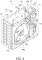
- FIG. 4 is a perspective view of the air conditioner outdoor unit, with some members of the casing and so forth having been detached therefrom to expose the humidifying unit.
- the main body of an electrical component box, the grille, and the top panel are detached.
- an imaginary plane F1 is shown in the place where part of the front panel further detached from the state in FIG. 3 was located.
- FIG. 5 is a plan view of the air conditioner outdoor unit in a state in which the top panel has been detached therefrom so that the humidifying unit is exposed. It should be noted that the arrow shown in FIG. 5 indicates a flow of air traveling through a section of a humidifying rotor functioning as an adsorption area.
- FIG. 6 is a sectional view, along line I-I, of the air conditioner outdoor unit in FIG. 2 .
- the side surfaces of the body casing 40 shown in FIG. 2 are configured by a left side panel 45 and a right side panel 47 as shown in FIG. 4 .
- the left side panel 45 is on the left side of the body casing 40 and the right side panel 47 is on the right side of the body casing 40.
- the left side panel 45 is molded in a lattice shape and has numerous openings 45a so that the outside air can be guided from the left side to the outdoor heat exchanger 33.
- the right side panel 47 configures part of the rear surface and the entire right side surface of the body casing 40, from the right end of the outdoor heat exchanger 33 to the right side surface of the body casing 40.
- an inlet 72 (see FIG. 1 ) serving as an inlet of a desorption path running through a later-described desorption area is formed in the right side panel 47.
- the partition panel 43 dividing the blower compartment S1 and the machine compartment S2 of the body casing 40 from each other extends forward from the right end of the outdoor heat exchanger 33 as shown in FIG. 5 and extends upward from the bottom panel 49 as shown in FIG. 6 .
- the rear portion of the partition panel 43 extends from the bottom panel 49 to the top panel 48.
- an open portion 43a cut out from the upper edge to the substantially central portion is formed in order to fit the humidifying unit 60 and so forth therein (see FIG. 4 and FIG. 6 ).
- the front end portion of the partition panel 43 is attached contacting the front panel 46.
- the electrical component box 50 is formed in a cuboid shape in such a way that its inside is a closed space, and electrical components (not shown in the drawings) for controlling the various types of devices with which the air conditioner outdoor unit 30 is equipped are housed inside.
- the electrical component box 50 is placed on the rear portion of the humidifying unit 60. It should be noted that the compressor 31 and so forth shown in FIG. 6 are installed on the far side of the partition panel 43, that is, in the machine compartment S2.
- the outdoor heat exchanger 33 is shaped like an "L" as seen from above. That is to say, the outdoor heat exchanger 33 has a first section 33a, which faces the left side panel 45 of the body casing 40, and a second section 33b, which faces the back surface of the body casing 40. Furthermore, the outdoor heat exchanger 33 has a height that spans the distance from the bottom panel 49 to the top panel 48. Additionally, the outdoor heat exchanger 33 has numerous fins (not shown in the drawings) extending long in the height direction and heat transfer tubes (not shown in the drawings) attached horizontally through the fins. The heat transfer tubes are placed in numerous rows in the height direction as a result of being bent plural times at both end portions of the outdoor heat exchanger 33.
- the outdoor fan 39 is a propeller fan, and is a fan that blows out toward the front surface side (front side) of the air conditioner outdoor unit 30 the outside air sucked in through the outdoor heat exchanger 33 from the back surface side (rear side) of the outdoor heat exchanger 33.
- the outdoor fan 39 has a fan motor 39a and the propeller 39b that is driven by the fan motor 39a.
- a rotating shaft of the propeller 39b is coupled to a drive shaft of the fan motor 39a.
- the propeller 39b is placed in such a way that part of it is inside a space surrounded by a bell mouth 46a.
- a plate-shaped portion 46b on the peripheral edge of the bell mouth 46a is attached to the front panel 46 in such a way that the ring-shaped bell mouth 46a is placed around the outlet 44.
- the fan motor 39a is supported by a fan motor base 39c (see FIG. 6 ).
- the fan motor base 39c is attached to the bottom panel 49 and the front panel 46.
- FIG. 7 is an exploded view of the humidifying unit.
- FIG. 8 is a partially enlarged perspective view in which part of the humidifying unit is enlarged.
- the humidifying unit 60 has an adsorption path running through an adsorption area 61 and a desorption path running through a desorption area 62, with the adsorption path being positioned in the blower compartment S1 of the air conditioner outdoor unit 30 and the desorption path being positioned in the machine compartment S2 of the air conditioner outdoor unit 30.
- the position of the upper end of the humidifying unit 60 is placed at substantially the same height as an upper end (top portion) 33t of the outdoor heat exchanger 33 (see FIG. 4 and FIG. 6 ) or in a lower position than the upper end 33t of the outdoor heat exchanger 33.
- the upper end of the humidifying unit 60 coincides with the upper end of a frame 70 when attached to the air conditioner outdoor unit 30.
- the upper end of a later-described humidifying rotor 63 is in a lower position than the upper end 33t of the outdoor heat exchanger 33.
- the relationship between the height positions of the humidifying rotor 63 and the outdoor heat exchanger 33 is not limited to this provided that the product size of the air conditioner outdoor unit 30 does not become too large.
- the height of the upper end of the humidifying rotor 63 may also coincide with the height of the upper end 33t of the outdoor heat exchanger 33 or may be in a position slightly higher than the upper end 33t of the outdoor heat exchanger 33 (e.g., a position higher by about 10% of the height of the outdoor heat exchanger 33).
- the humidifying unit 60 is mainly equipped with the humidifying rotor 63, a heater 71, and a turbo fan 75. Additionally, the disc-shaped humidifying rotor 63 includes the adsorption area 61 that adsorbs moisture in the outside air and the desorption area 62 that as a result of being heated desorbs the moisture adsorbed in the adsorption area 61. The heater 71 and the turbo fan 75 are placed with respect to the desorption area 62. Furthermore, the humidifying rotor 63, the heater 71, and the turbo fan 75 are secured to the frame 70.
- the heater 71 and the humidifying rotor 63 are secured to a support plate 73, and the support plate 73 is attached to the front surface side of the frame 70 (see FIG. 7 and FIG. 8 ). Furthermore, the turbo fan 75 is attached to the back surface side of the frame 70 on the opposite side of the surface to which the support plate 73 is attached (see FIG. 7 and FIG. 8 ).
- a unit guide 69 configuring part of the adsorption path is disposed in the humidifying unit 60.
- the unit guide 69 extends in the direction of the front panel 46 from the outer peripheral edge of the humidifying rotor 63 or the neighborhood thereof.
- the shape of the unit guide 69 is not particularly limited provided that it is a shape that extends toward the outdoor heat exchanger 33 from the outer peripheral edge of the humidifying rotor 63 or the neighborhood thereof.
- An air inlet 61a is formed opposing the adsorption area 61 in the front side of the unit guide 69, and an air outlet 61b is formed in the rear side.
- the humidifying rotor 63 is a single disc-shaped adsorption and desorption material, with the section functioning as the adsorption area 61 being positioned between the outdoor heat exchanger 33 and the front panel 46 in the blower compartment S1 and the section functioning as the desorption area 62 being positioned between the front panel 46 and the electrical component box 50 in the machine compartment S2.
- the humidifying rotor 63 is a zeolite rotor having a honeycomb structure formed by firing zeolite, for example.
- the humidifying rotor 63 is attached so as to rotate using the center of the disc as a rotational axis, and is driven to rotate by power from a rotor drive motor 65 transmitted to a gear 65a disposed on the periphery of the humidifying rotor 63.
- the adsorbent such as zeolite forming the humidifying rotor 63 has the property that it adsorbs moisture from air at a normal temperature, for example, and desorbs moisture as a result of being heated to a high temperature by the heater 71 or the like and reaching a higher temperature than the normal temperature. That is, the region of the humidifying rotor 63 exposed to air at a normal temperature is the adsorption area 61 that adsorbs moisture from the outside air, and the region where the humidifying rotor 63 is heated using the heater 71 is the desorption area 62 that desorbs the adsorbed moisture.
- the humidifying rotor 63 is placed in such a way that its rotational axis extends in the forward and rearward direction. That is, the main surface of the humidifying rotor 63 is disposed along a plane (e.g., the front panel 46) perpendicular to the forward and rearward direction in which the outdoor fan 39 generates the air flow.
- a plane e.g., the front panel 46
- the main surface of the humidifying rotor is disposed along a perpendicular plane
- the main surface of the humidifying rotor 63 described here is an example of a case where it is not inclined at all with respect to the perpendicular plane.
- disposing the main surface of the humidifying rotor along a plane perpendicular to the forward and rearward direction in which the outdoor fan generates the air flow results in a vertical placement where the width direction (thickness direction) of the humidifying rotor extends forward and rearward so that the humidifying rotor does not take up space in the forward and rearward direction.
- the humidifying rotor 63 is placed in the open portion 43a of the partition panel 43 in such a way that the adsorption area 61 is positioned in the blower compartment S1 of the air conditioner outdoor unit 30 and the desorption area 62 is positioned in the machine compartment S2 of the air conditioner outdoor unit 30.
- the adsorption area 61 is positioned between the outdoor heat exchanger 33 and the front panel 46 in the blower compartment S1, and the humidifying unit 60 is placed alongside the outdoor fan 39.
- the humidifying unit 60 is placed adjacent to the outdoor fan 39 diagonally above and to the right of the outdoor fan 39.
- the adsorption area 61 of the humidifying unit 60 faces a section where there is not the front panel 46 of the body casing 40 so that the adsorption area 61 is exposed to the outside of the body casing 40. Because the humidifying unit 60 is placed in this way, negative pressure is created inside the body casing 40 with respect to the outside of the body casing 40, so air for humidification can be delivered from the outside of the body casing 40 to the adsorption area 61. Moreover, using a blocking surface 81 (see FIG. 2 ) disposed in the grille 80, an air flow can be pushed into the adsorption area 61 from the outside of the body casing 40 using the air flow that becomes blown out to the outside from the body casing 40 by the outdoor fan 39.
- the heater 71 is disposed opposing the section of the humidifying rotor 63 functioning as the desorption area 62.
- the heater 71 has a structure where an electric heating wire (not shown in the drawings) is disposed inside a tubular case 71a shown in FIG. 7 , and the outside air sucked in from the inlet 72 (see FIG. 1 ) and delivered to the humidifying rotor 63 is heated by the electric heating wire.
- an electric heating wire (not shown in the drawings) is disposed inside a tubular case 71a shown in FIG. 7 , and the outside air sucked in from the inlet 72 (see FIG. 1 ) and delivered to the humidifying rotor 63 is heated by the electric heating wire.
- the humidifying rotor 63 when the heated air passes through the openings in the honeycomb structure of the humidifying rotor 63, moisture is desorbed from the humidifying rotor 63 so that the air sucked into the turbo fan 75 is humidified.
- the heater 71 is attached to a heater support member 74.
- the heater support member 74 has a semicircular base portion 74a and an outer wall portion 74b that is disposed erectly from the peripheral edge portion of the base portion 74a, and the side (the humidifying rotor 63 side) of the heater support member 74 is open. Additionally, the heater 71 is attached to the base portion 74a in such a way that it is covered by the heater support member 74.
- the heater support member 74 configures part of the desorption path. It should be noted that the case of the heater 71 and the heater support member 74 are made of sheet metal. Furthermore, the heater 71 is installed in the machine compartment S2 of the air conditioner outdoor unit 30 and is placed on the opposite side of the electrical component box 50 with the humidifying rotor 63 being sandwiched in between.
- the turbo fan 75 generates an air flow heading from the air conditioner outdoor unit 30 to the air conditioner indoor unit 20. Furthermore, the turbo fan 75 is placed opposing the heater 71 with the humidifying rotor 63 being sandwiched in between, and, as shown in FIG. 3 and FIG. 5 , is installed in the machine compartment S2.
- the turbo fan 75 has a fan motor 75a, an impeller 75b that is driven by the fan motor 75a, and a fan casing 75c that houses the impeller 75b.
- the rotational axis of the impeller 75b of the turbo fan 75 is placed so as to extend in the forward and rearward direction, and the turbo fan 75 has a vertical placement that does not take up space in the forward and rearward direction.
- a suction portion 76 of the turbo fan 75 opens rearward.
- a discharge portion 77 of the turbo fan 75 opens downward.
- a humidification conduit 78 is connected to the discharge portion 77, and the supply air duct 18 is attached to the humidification conduit 78. For this reason, air sucked in from the suction portion 76 of the turbo fan 75 is guided via the humidification conduit 78 to the supply air duct 18, travels though the supply air duct 18, and is blown out from the outlet 24 of the air conditioner indoor unit 20.
- FIG. 9 is a perspective view in which the grille is seen from its back surface side.
- the grille 80 has the blocking surface 81, a lattice-shaped portion 82, in which crosspieces are vertically and horizontally put together and in which numerous openings are formed, and an attachment frame 83 for attachment to the front panel 46.
- an air direction guide 84 for guiding the air flow to the adsorption area 61 of the humidifying unit 60 is formed on the rear surface of the blocking surface 81.
- the air direction guide 84 is configured by an upper rib 84a and a lower rib 84b.
- the left end of the blocking surface 81 reaches as far as part of the outlet 44. In other words, part of the right side of the outlet 44 opposes the blocking surface 81. For that reason, part of the air flow blown out from the outlet 44 is blocked by the blocking surface 81. Most of the air flow blocked by the blocking surface 81 is guided to the adsorption area 61 by the air direction guide 84.
- the upper rib 84a extends diagonally upward and rightward from a position diagonally on the right and upper side of the outlet 44, and the lower rib 84b first extends rightward from a position diagonally on the right and lower side of the outlet 44 and then gradually changes direction upward.
- the attachment frame 83 of the grille 80 has substantially the same height as the upper rib 84a and the lower rib 84b, and when the grille 80 is attached, the attachment frame 83 around the grille 80 and the upper rib 84a and the lower rib 84b contact the front panel 46. For that reason, the outlet 44 and the air inlet 61a of the adsorption path are interconnected by a space surrounded by the front panel 46, the air direction guide 84, and the blocking surface 81.
- the space surrounded by the air direction guide 84 extends along the rotational direction of the outdoor fan 39 (a direction counter-clockwise as seen from the front). For that reason, the air is pushed in the direction of arrow A1 in FIG. 3
- the humidifying operation is performed in combination with the heating operation. For this reason, during the humidifying operation, the compressor 31 and the outdoor fan 39 are driven. Furthermore, during the humidifying operation, the humidifying rotor 63 is rotated at a predetermined rotational speed by power from the rotor drive motor 65, the heater 71 is on, and the turbo fan 75 runs.
- the humidifying rotor 63 rotates, the moisture adsorbed by the adsorption of the humidifying rotor 63 functioning as the adsorption area 61 is carried as the humidifying rotor 63 rotates, so that the moisture that had been adsorbed is desorbed by the desorption of the humidifying rotor 63 functioning as the desorption area 62. In this way, the air around the desorption area 62 becomes humidified. Furthermore, the humidifying rotor 63 of the present embodiment rotates counter-clockwise as seen from the front, and the section that functioned as the adsorption area 61 functions as the desorption area 62 when it rotates and comes to the position opposing the heater support member 74.
- the outdoor fan 39 is driven, which generates an air flow in which outside air is sucked in through the outdoor heat exchanger 33 from the back surface side of the outdoor heat exchanger 33 and is blown out to the front surface side of the air conditioner outdoor unit 30.
- Part of the air flow blown out from the outlet 44 flows in the space configured by the front panel 46, the air direction guide 84, and the blocking surface 81 and is guided to the adsorption area 61.
- the air arriving at the adsorption area 61 passes from front to back through the adsorption area 61, enters the blower compartment S1, and is blown out via the bell mouth 46a from the outlet 44.
- the path of the air flow at this time is the path indicated by arrow A2 in FIG. 4 , arrow A3 in FIG. 5 , and arrow A4 in FIG. 6 , for example.
- the turbo fan 75 is driven, which generates an air flow heading from the air conditioner outdoor unit 30 to the air conditioner indoor unit 20-that is, an air flow in which outside air sucked in from the inlet 72 is blown out via the humidifying rotor 63 and the heater 71 to the supply air duct 18.
- the outside air sucked in from the inlet 72 first goes around to the rear side of the humidifying rotor 63, passes from back to front through the humidifying rotor 63, and arrives at the heater 71. Then, the outside air arriving at the heater 71 is heated by the heater 71, thereafter proceeds to the humidifying rotor 63, and passes from front to back through the section of the humidifying rotor 63 functioning as the desorption area 62.
- the section of the humidifying rotor 63 positioned in the blower compartment S1 functions as the adsorption area 61. Furthermore, in the humidifying rotor 63 positioned in the machine compartment S2, the section positioned on the air flow downstream side of the heater 71 functions as the desorption area 62, and the section other than this functions as a reheating area 64 (see FIG. 3 ).
- the reheating area 64 is a section where the outside air sucked in from the inlet 72 first passes through the humidifying rotor 63.
- the humidifying rotor 63 rotates counter-clockwise, so arbitrary places on the humidifying rotor 63 change the function in the order of the adsorption area 61, the desorption area 62, and the reheating area 64.
- the reheating area 64 is the section that had functioned as the desorption area 62 until just before, so it reaches a high temperature. For this reason, the outside air sucked in from the inlet 72 passes through the reheating area 64 and is thereby heated by the heat of the reheating area 64. Furthermore, the reheating area 64 is cooled as a result of the outside air passing through it, and thereafter functions as the adsorption area 61 because of the rotation of the humidifying rotor 63.
- the humidifying rotor 63 is installed along the front panel 46 (an example of a plane perpendicular to the forward and rearward direction) perpendicular to the direction of the air flow blown out by the outdoor fan 39 (an example of a fan).
- the humidifying rotor 63 functions as the adsorption area 61 in the blower compartment S1 and functions as the desorption area 62 in the machine compartment S2. Additionally, the air flow is guided to the section functioning as the adsorption area 61 from downstream of the outdoor fan 39 through the space (an example of an air flow path) surrounded by the front panel 46, the air direction guide 84, and the blocking surface 81.
- the outdoor fan 39 is doubly used as blowing means for blowing air to the adsorption area 61. Even when doubly using the outdoor fan 39 as means for blowing air to the adsorption area 61 in this way, a sufficient adsorption air volume can be ensured by the space surrounded by the front panel 46, the air direction guide 84, and the blocking surface 81.
- the humidifying rotor 63 is installed along the front panel 46, so compared to a configuration where the humidifying rotor is placed along a horizontal plane, it becomes possible to increase the distance between the outdoor heat exchanger 33 and the humidifying rotor 63 so that a drop in performance associated with it becoming difficult for the outside air to flow to the outdoor heat exchanger 33 can be prevented. As a result, a drop in the performance of the outdoor heat exchanger 33 is prevented.
- part of the blocking surface 81 of the grille 80 attached to the front surface of the body casing 40 covers part of the outlet 44. For that reason, a diversion that guides the air flow to the air flow path by means of the blocking surface 81 downstream of the outdoor fan 39 takes place.
- the air flow can be pushed, by the air pressure generated by the outdoor fan 39 in this way, into the air flow path to allow the air flow to flow to the section of the humidifying rotor 63 functioning as the adsorption area 61. As a result, it becomes easier to ensure the adsorption air volume that passes through the adsorption area 61.
- the space surrounded by the air direction guide 84 extends along the rotational direction of the outdoor fan 39, so the air flow diverted by the blocking surface 81 can be efficiently guided by the air direction guide 84 to the air flow path, and the adsorption air volume can be improved.
- the electrical component box 50 is placed on the rear surface side of the humidifying rotor 63, and the humidifying rotor 63 is placed on the front surface side of the body casing 40. Because of this placement, the humidifying rotor 63 can be placed near the grille 80, so it becomes easier to guide the air flow to the section of the humidifying rotor 63 functioning as the adsorption area 61 and it becomes easier to ensure the adsorption air volume.
- the humidifying rotor 63 is shaped like a disc, but the shape of the humidifying rotor used in the present invention may be any shape provided that it is plate-shaped. Furthermore, in addition to the humidifying rotor 63 configured by a single plate-shaped adsorption and desorption material described above, a single plate-shaped humidifying rotor configured by combining plural adsorption and desorption materials having the same shape or differing shapes can also be used for the single plate-shaped adsorption and desorption material that can be used in the present invention.
- the humidifying unit 60 is placed in such a way that all of the section of the humidifying rotor 63 functioning as the adsorption area 61 is positioned in the blower compartment S1 of the air conditioner outdoor unit 30.
- the adsorption area 61 positioned in the blower compartment S1 may also be part of the adsorption area 61.
- the humidifying unit 60 is placed in such a way that all of the section of the humidifying rotor 63 functioning as the desorption area 62 is positioned in the machine compartment S2 of the air conditioner outdoor unit 30.
- the desorption area 62 positioned in the machine compartment S2 may also be part of the desorption area 62.
- the humidifying unit 60 is placed in such a way that all of the section of the humidifying rotor 63 functioning as the adsorption area 61 is positioned in the blower compartment S1 of the air conditioner outdoor unit 30.
- the section of the humidifying rotor 63 functioning as the adsorption area 61 may also be placed entirely in the machine compartment S2.
- the grille 80 is extended as far as the place where the adsorption area 61 of the humidifying unit 60 moves.
- the air flow is guided from downstream of the outdoor fan 39 through the space (an example of an air flow path) surrounded by the front panel 46, the air direction guide 84, and the blocking surface 81 to the adsorption area 61 placed in the machine compartment S2.
Landscapes
- Engineering & Computer Science (AREA)
- Chemical & Material Sciences (AREA)
- Combustion & Propulsion (AREA)
- Mechanical Engineering (AREA)
- General Engineering & Computer Science (AREA)
- Air Humidification (AREA)
- Other Air-Conditioning Systems (AREA)
Claims (4)
- Klimaanlagenaußeneinheit, umfassend:ein Körpergehäuse (40), das ein Gebläsefach (SI) aufweist, durch welches ein Luftstrom von einer vorderen Oberflächenseite zu dem Außenbereich verläuft;einen Ventilator (39), der in dem Gebläsefach platziert ist und zum Generieren eines Luftstroms dient, der hin zu der vorderen Oberflächenseite des Körpergehäuses strömt;einen plattenförmigen Befeuchtungsrotor (63), der eine Adsorptionsfläche, die Feuchtigkeit in der Außenbereichsluft adsorbiert, und eine Desorptionsfläche, die in Reaktion darauf, erhitzt zu werden, die in der Adsorptionsfläche adsorbierte Feuchtigkeit desorbiert, beinhaltet; undeine Luftstromweg, um es dem Luftstrom zu ermöglichen, von stromabwärts des Ventilators zu der Adsorptionsfläche zu strömen,dadurch gekennzeichnet, dass der plattenförmige Befeuchtungsrotor (63) entlang einer Ebene installiert ist, die senkrecht zu einer vorwärtigen und rückwärtigen Richtung ist.
- Klimaanlagenaußeneinheit nach Anspruch 1, weiter umfassend ein Gitter (80), das an der vorderen Oberfläche des Körpergehäuses befestigt ist und eine Abblockoberfläche zum Ablenken aufweist, um Teil des Luftstroms, der von dem Ventilator generiert wird, stromabwärts des Ventilators zu dem Luftstromweg zu führen.
- Klimaanlagenaußeneinheit nach Anspruch 2, wobei das Gitter eine Luftrichtungsführung aufweist, die auf einer hinteren Oberfläche der Abblockoberfläche angeordnet ist und mit der Luftrichtungsführung den Luftstromweg derart umgibt, dass der Luftstromweg sich entlang der Rotationsrichtung des Ventilators erstreckt.
- Klimaanlagenaußeneinheit nach einem der Ansprüche 1 bis 3, weiter umfassend einen Kasten elektrischer Komponenten (50), der ein elektrisches Teil zum Antreiben des Ventilators beherbergt, wobei
der Ventilator auf der vorderen Oberflächenseite des Körpergehäuses platziert ist, und der Befeuchtungsrotor weiter auf der vorderen Oberflächenseite des Körpergehäuses platziert ist als der Kasten elektrischer Komponenten.
Applications Claiming Priority (2)
| Application Number | Priority Date | Filing Date | Title |
|---|---|---|---|
| JP2013240085A JP5796618B2 (ja) | 2013-11-20 | 2013-11-20 | 空調室外ユニット |
| PCT/JP2014/080613 WO2015076287A1 (ja) | 2013-11-20 | 2014-11-19 | 空調室外ユニット |
Publications (3)
| Publication Number | Publication Date |
|---|---|
| EP3073202A1 EP3073202A1 (de) | 2016-09-28 |
| EP3073202A4 EP3073202A4 (de) | 2016-12-28 |
| EP3073202B1 true EP3073202B1 (de) | 2018-02-21 |
Family
ID=53179547
Family Applications (1)
| Application Number | Title | Priority Date | Filing Date |
|---|---|---|---|
| EP14863966.9A Not-in-force EP3073202B1 (de) | 2013-11-20 | 2014-11-19 | Klimaanlagenausseneinheit |
Country Status (6)
| Country | Link |
|---|---|
| EP (1) | EP3073202B1 (de) |
| JP (1) | JP5796618B2 (de) |
| CN (1) | CN105745499B (de) |
| AU (1) | AU2014354062B2 (de) |
| ES (1) | ES2662069T3 (de) |
| WO (1) | WO2015076287A1 (de) |
Families Citing this family (8)
| Publication number | Priority date | Publication date | Assignee | Title |
|---|---|---|---|---|
| JP6314958B2 (ja) * | 2015-10-30 | 2018-04-25 | ダイキン工業株式会社 | 空調機の室外ユニット |
| JP2017083147A (ja) * | 2015-10-30 | 2017-05-18 | ダイキン工業株式会社 | 空調機の室外ユニット |
| CN108518760B (zh) * | 2018-04-17 | 2020-02-04 | 青岛海尔空调器有限总公司 | 空调器 |
| CN108469089A (zh) * | 2018-04-17 | 2018-08-31 | 青岛海尔空调器有限总公司 | 加湿模块 |
| WO2020157824A1 (ja) | 2019-01-29 | 2020-08-06 | 三菱電機株式会社 | 空気調和機の室外機 |
| JP6970930B1 (ja) * | 2020-10-05 | 2021-11-24 | パナソニックIpマネジメント株式会社 | 空気調和機 |
| CN113418242A (zh) * | 2021-06-03 | 2021-09-21 | 重庆海尔空调器有限公司 | 无水加湿装置、空调器 |
| JP7654509B2 (ja) * | 2021-08-31 | 2025-04-01 | ダイキン工業株式会社 | 加湿装置 |
Family Cites Families (9)
| Publication number | Priority date | Publication date | Assignee | Title |
|---|---|---|---|---|
| JP4677658B2 (ja) * | 2000-09-12 | 2011-04-27 | ダイキン工業株式会社 | 空気調和機 |
| JP2002089897A (ja) * | 2000-09-12 | 2002-03-27 | Daikin Ind Ltd | 空気調和機 |
| JP2004053198A (ja) * | 2002-07-23 | 2004-02-19 | Daikin Ind Ltd | 空気調和機の室外機および空気調和機 |
| JP3731570B2 (ja) * | 2002-08-06 | 2006-01-05 | ダイキン工業株式会社 | 空気調和機の加湿ユニットおよび空気調和機 |
| JP2008190828A (ja) * | 2007-02-07 | 2008-08-21 | Toshiba Carrier Corp | 空気調和機及び吸着・脱離装置 |
| JP5234205B2 (ja) * | 2011-06-01 | 2013-07-10 | ダイキン工業株式会社 | 空気調和装置の室外機 |
| JP2012251692A (ja) | 2011-06-01 | 2012-12-20 | Daikin Industries Ltd | 空気調和装置の室外機 |
| CN202792319U (zh) * | 2012-08-20 | 2013-03-13 | 四川顶点建筑工程有限公司 | 增强型吸湿空气调节系统 |
| CN203231433U (zh) * | 2013-04-15 | 2013-10-09 | 广东美的制冷设备有限公司 | 加湿空调室外机 |
-
2013
- 2013-11-20 JP JP2013240085A patent/JP5796618B2/ja not_active Expired - Fee Related
-
2014
- 2014-11-19 ES ES14863966.9T patent/ES2662069T3/es active Active
- 2014-11-19 EP EP14863966.9A patent/EP3073202B1/de not_active Not-in-force
- 2014-11-19 WO PCT/JP2014/080613 patent/WO2015076287A1/ja not_active Ceased
- 2014-11-19 CN CN201480062941.6A patent/CN105745499B/zh not_active Expired - Fee Related
- 2014-11-19 AU AU2014354062A patent/AU2014354062B2/en not_active Ceased
Non-Patent Citations (1)
| Title |
|---|
| None * |
Also Published As
| Publication number | Publication date |
|---|---|
| EP3073202A4 (de) | 2016-12-28 |
| CN105745499B (zh) | 2017-05-17 |
| EP3073202A1 (de) | 2016-09-28 |
| JP2015098995A (ja) | 2015-05-28 |
| ES2662069T3 (es) | 2018-04-05 |
| WO2015076287A1 (ja) | 2015-05-28 |
| JP5796618B2 (ja) | 2015-10-21 |
| AU2014354062B2 (en) | 2016-07-14 |
| CN105745499A (zh) | 2016-07-06 |
Similar Documents
| Publication | Publication Date | Title |
|---|---|---|
| EP3073202B1 (de) | Klimaanlagenausseneinheit | |
| JP5234205B2 (ja) | 空気調和装置の室外機 | |
| EP3054226B1 (de) | Klimaanlagen-ausseneinheit | |
| JP5672284B2 (ja) | 空気調和装置の室外機 | |
| JP5532100B2 (ja) | 空気調和装置の室外機 | |
| JP5533970B2 (ja) | 空気調和装置の室外機 | |
| JP5532099B2 (ja) | 空気調和装置の室外機 | |
| JP2015098996A (ja) | 空調室外ユニット | |
| CN203478459U (zh) | 室外机 | |
| JP5910697B2 (ja) | 空気調和装置の室外機 | |
| WO2015064537A1 (ja) | 空調室外ユニット | |
| JP5659954B2 (ja) | 空気調和装置の室外機 | |
| JP2012251691A (ja) | 空気調和装置の室外機 | |
| WO2015046013A1 (ja) | 空調室外ユニット | |
| JP2015098992A (ja) | 空調室外ユニット | |
| JP6094213B2 (ja) | 加湿ユニット及び室外機 | |
| JP2024039536A (ja) | 空気調和装置 | |
| JP2014126318A (ja) | 室外機 |
Legal Events
| Date | Code | Title | Description |
|---|---|---|---|
| PUAI | Public reference made under article 153(3) epc to a published international application that has entered the european phase |
Free format text: ORIGINAL CODE: 0009012 |
|
| 17P | Request for examination filed |
Effective date: 20160610 |
|
| AK | Designated contracting states |
Kind code of ref document: A1 Designated state(s): AL AT BE BG CH CY CZ DE DK EE ES FI FR GB GR HR HU IE IS IT LI LT LU LV MC MK MT NL NO PL PT RO RS SE SI SK SM TR |
|
| AX | Request for extension of the european patent |
Extension state: BA ME |
|
| A4 | Supplementary search report drawn up and despatched |
Effective date: 20161128 |
|
| RIC1 | Information provided on ipc code assigned before grant |
Ipc: F24F 1/48 20110101ALI20161122BHEP Ipc: F24F 6/08 20060101AFI20161122BHEP Ipc: F24F 6/16 20060101ALI20161122BHEP Ipc: F24F 1/22 20110101ALI20161122BHEP |
|
| DAX | Request for extension of the european patent (deleted) | ||
| RIC1 | Information provided on ipc code assigned before grant |
Ipc: F24F 6/00 20060101ALI20170823BHEP Ipc: F24F 3/14 20060101ALI20170823BHEP Ipc: F24F 1/46 20110101ALI20170823BHEP Ipc: F24F 6/08 20060101AFI20170823BHEP Ipc: F24F 1/48 20110101ALI20170823BHEP Ipc: F24F 6/16 20060101ALI20170823BHEP Ipc: F24F 1/06 20110101ALI20170823BHEP Ipc: F24F 1/22 20110101ALI20170823BHEP |
|
| GRAP | Despatch of communication of intention to grant a patent |
Free format text: ORIGINAL CODE: EPIDOSNIGR1 |
|
| STAA | Information on the status of an ep patent application or granted ep patent |
Free format text: STATUS: GRANT OF PATENT IS INTENDED |
|
| INTG | Intention to grant announced |
Effective date: 20171020 |
|
| GRAS | Grant fee paid |
Free format text: ORIGINAL CODE: EPIDOSNIGR3 |
|
| GRAA | (expected) grant |
Free format text: ORIGINAL CODE: 0009210 |
|
| STAA | Information on the status of an ep patent application or granted ep patent |
Free format text: STATUS: THE PATENT HAS BEEN GRANTED |
|
| AK | Designated contracting states |
Kind code of ref document: B1 Designated state(s): AL AT BE BG CH CY CZ DE DK EE ES FI FR GB GR HR HU IE IS IT LI LT LU LV MC MK MT NL NO PL PT RO RS SE SI SK SM TR |
|
| REG | Reference to a national code |
Ref country code: GB Ref legal event code: FG4D |
|
| REG | Reference to a national code |
Ref country code: CH Ref legal event code: EP |
|
| REG | Reference to a national code |
Ref country code: AT Ref legal event code: REF Ref document number: 972181 Country of ref document: AT Kind code of ref document: T Effective date: 20180315 |
|
| REG | Reference to a national code |
Ref country code: IE Ref legal event code: FG4D |
|
| REG | Reference to a national code |
Ref country code: DE Ref legal event code: R096 Ref document number: 602014021476 Country of ref document: DE |
|
| REG | Reference to a national code |
Ref country code: ES Ref legal event code: FG2A Ref document number: 2662069 Country of ref document: ES Kind code of ref document: T3 Effective date: 20180405 |
|
| REG | Reference to a national code |
Ref country code: NL Ref legal event code: MP Effective date: 20180221 |
|
| REG | Reference to a national code |
Ref country code: LT Ref legal event code: MG4D |
|
| REG | Reference to a national code |
Ref country code: AT Ref legal event code: MK05 Ref document number: 972181 Country of ref document: AT Kind code of ref document: T Effective date: 20180221 |
|
| PG25 | Lapsed in a contracting state [announced via postgrant information from national office to epo] |
Ref country code: HR Free format text: LAPSE BECAUSE OF FAILURE TO SUBMIT A TRANSLATION OF THE DESCRIPTION OR TO PAY THE FEE WITHIN THE PRESCRIBED TIME-LIMIT Effective date: 20180221 Ref country code: CY Free format text: LAPSE BECAUSE OF FAILURE TO SUBMIT A TRANSLATION OF THE DESCRIPTION OR TO PAY THE FEE WITHIN THE PRESCRIBED TIME-LIMIT Effective date: 20180221 Ref country code: LT Free format text: LAPSE BECAUSE OF FAILURE TO SUBMIT A TRANSLATION OF THE DESCRIPTION OR TO PAY THE FEE WITHIN THE PRESCRIBED TIME-LIMIT Effective date: 20180221 Ref country code: NL Free format text: LAPSE BECAUSE OF FAILURE TO SUBMIT A TRANSLATION OF THE DESCRIPTION OR TO PAY THE FEE WITHIN THE PRESCRIBED TIME-LIMIT Effective date: 20180221 Ref country code: NO Free format text: LAPSE BECAUSE OF FAILURE TO SUBMIT A TRANSLATION OF THE DESCRIPTION OR TO PAY THE FEE WITHIN THE PRESCRIBED TIME-LIMIT Effective date: 20180521 Ref country code: FI Free format text: LAPSE BECAUSE OF FAILURE TO SUBMIT A TRANSLATION OF THE DESCRIPTION OR TO PAY THE FEE WITHIN THE PRESCRIBED TIME-LIMIT Effective date: 20180221 |
|
| PG25 | Lapsed in a contracting state [announced via postgrant information from national office to epo] |
Ref country code: LV Free format text: LAPSE BECAUSE OF FAILURE TO SUBMIT A TRANSLATION OF THE DESCRIPTION OR TO PAY THE FEE WITHIN THE PRESCRIBED TIME-LIMIT Effective date: 20180221 Ref country code: AT Free format text: LAPSE BECAUSE OF FAILURE TO SUBMIT A TRANSLATION OF THE DESCRIPTION OR TO PAY THE FEE WITHIN THE PRESCRIBED TIME-LIMIT Effective date: 20180221 Ref country code: BG Free format text: LAPSE BECAUSE OF FAILURE TO SUBMIT A TRANSLATION OF THE DESCRIPTION OR TO PAY THE FEE WITHIN THE PRESCRIBED TIME-LIMIT Effective date: 20180521 Ref country code: GR Free format text: LAPSE BECAUSE OF FAILURE TO SUBMIT A TRANSLATION OF THE DESCRIPTION OR TO PAY THE FEE WITHIN THE PRESCRIBED TIME-LIMIT Effective date: 20180522 Ref country code: RS Free format text: LAPSE BECAUSE OF FAILURE TO SUBMIT A TRANSLATION OF THE DESCRIPTION OR TO PAY THE FEE WITHIN THE PRESCRIBED TIME-LIMIT Effective date: 20180221 Ref country code: SE Free format text: LAPSE BECAUSE OF FAILURE TO SUBMIT A TRANSLATION OF THE DESCRIPTION OR TO PAY THE FEE WITHIN THE PRESCRIBED TIME-LIMIT Effective date: 20180221 |
|
| PG25 | Lapsed in a contracting state [announced via postgrant information from national office to epo] |
Ref country code: AL Free format text: LAPSE BECAUSE OF FAILURE TO SUBMIT A TRANSLATION OF THE DESCRIPTION OR TO PAY THE FEE WITHIN THE PRESCRIBED TIME-LIMIT Effective date: 20180221 Ref country code: RO Free format text: LAPSE BECAUSE OF FAILURE TO SUBMIT A TRANSLATION OF THE DESCRIPTION OR TO PAY THE FEE WITHIN THE PRESCRIBED TIME-LIMIT Effective date: 20180221 Ref country code: PL Free format text: LAPSE BECAUSE OF FAILURE TO SUBMIT A TRANSLATION OF THE DESCRIPTION OR TO PAY THE FEE WITHIN THE PRESCRIBED TIME-LIMIT Effective date: 20180221 Ref country code: EE Free format text: LAPSE BECAUSE OF FAILURE TO SUBMIT A TRANSLATION OF THE DESCRIPTION OR TO PAY THE FEE WITHIN THE PRESCRIBED TIME-LIMIT Effective date: 20180221 |
|
| REG | Reference to a national code |
Ref country code: DE Ref legal event code: R097 Ref document number: 602014021476 Country of ref document: DE |
|
| PG25 | Lapsed in a contracting state [announced via postgrant information from national office to epo] |
Ref country code: SM Free format text: LAPSE BECAUSE OF FAILURE TO SUBMIT A TRANSLATION OF THE DESCRIPTION OR TO PAY THE FEE WITHIN THE PRESCRIBED TIME-LIMIT Effective date: 20180221 Ref country code: DK Free format text: LAPSE BECAUSE OF FAILURE TO SUBMIT A TRANSLATION OF THE DESCRIPTION OR TO PAY THE FEE WITHIN THE PRESCRIBED TIME-LIMIT Effective date: 20180221 Ref country code: CZ Free format text: LAPSE BECAUSE OF FAILURE TO SUBMIT A TRANSLATION OF THE DESCRIPTION OR TO PAY THE FEE WITHIN THE PRESCRIBED TIME-LIMIT Effective date: 20180221 Ref country code: SK Free format text: LAPSE BECAUSE OF FAILURE TO SUBMIT A TRANSLATION OF THE DESCRIPTION OR TO PAY THE FEE WITHIN THE PRESCRIBED TIME-LIMIT Effective date: 20180221 |
|
| PLBE | No opposition filed within time limit |
Free format text: ORIGINAL CODE: 0009261 |
|
| STAA | Information on the status of an ep patent application or granted ep patent |
Free format text: STATUS: NO OPPOSITION FILED WITHIN TIME LIMIT |
|
| 26N | No opposition filed |
Effective date: 20181122 |
|
| PG25 | Lapsed in a contracting state [announced via postgrant information from national office to epo] |
Ref country code: SI Free format text: LAPSE BECAUSE OF FAILURE TO SUBMIT A TRANSLATION OF THE DESCRIPTION OR TO PAY THE FEE WITHIN THE PRESCRIBED TIME-LIMIT Effective date: 20180221 |
|
| REG | Reference to a national code |
Ref country code: CH Ref legal event code: PL |
|
| PG25 | Lapsed in a contracting state [announced via postgrant information from national office to epo] |
Ref country code: MC Free format text: LAPSE BECAUSE OF FAILURE TO SUBMIT A TRANSLATION OF THE DESCRIPTION OR TO PAY THE FEE WITHIN THE PRESCRIBED TIME-LIMIT Effective date: 20180221 Ref country code: LU Free format text: LAPSE BECAUSE OF NON-PAYMENT OF DUE FEES Effective date: 20181119 |
|
| REG | Reference to a national code |
Ref country code: BE Ref legal event code: MM Effective date: 20181130 |
|
| REG | Reference to a national code |
Ref country code: IE Ref legal event code: MM4A |
|
| PG25 | Lapsed in a contracting state [announced via postgrant information from national office to epo] |
Ref country code: LI Free format text: LAPSE BECAUSE OF NON-PAYMENT OF DUE FEES Effective date: 20181130 Ref country code: CH Free format text: LAPSE BECAUSE OF NON-PAYMENT OF DUE FEES Effective date: 20181130 |
|
| PG25 | Lapsed in a contracting state [announced via postgrant information from national office to epo] |
Ref country code: IE Free format text: LAPSE BECAUSE OF NON-PAYMENT OF DUE FEES Effective date: 20181119 |
|
| PG25 | Lapsed in a contracting state [announced via postgrant information from national office to epo] |
Ref country code: BE Free format text: LAPSE BECAUSE OF NON-PAYMENT OF DUE FEES Effective date: 20181130 |
|
| PG25 | Lapsed in a contracting state [announced via postgrant information from national office to epo] |
Ref country code: MT Free format text: LAPSE BECAUSE OF NON-PAYMENT OF DUE FEES Effective date: 20181119 |
|
| PGFP | Annual fee paid to national office [announced via postgrant information from national office to epo] |
Ref country code: DE Payment date: 20191122 Year of fee payment: 6 |
|
| PGFP | Annual fee paid to national office [announced via postgrant information from national office to epo] |
Ref country code: ES Payment date: 20191202 Year of fee payment: 6 Ref country code: FR Payment date: 20191122 Year of fee payment: 6 Ref country code: IT Payment date: 20191122 Year of fee payment: 6 |
|
| PG25 | Lapsed in a contracting state [announced via postgrant information from national office to epo] |
Ref country code: TR Free format text: LAPSE BECAUSE OF FAILURE TO SUBMIT A TRANSLATION OF THE DESCRIPTION OR TO PAY THE FEE WITHIN THE PRESCRIBED TIME-LIMIT Effective date: 20180221 |
|
| PGFP | Annual fee paid to national office [announced via postgrant information from national office to epo] |
Ref country code: GB Payment date: 20191108 Year of fee payment: 6 |
|
| PG25 | Lapsed in a contracting state [announced via postgrant information from national office to epo] |
Ref country code: PT Free format text: LAPSE BECAUSE OF FAILURE TO SUBMIT A TRANSLATION OF THE DESCRIPTION OR TO PAY THE FEE WITHIN THE PRESCRIBED TIME-LIMIT Effective date: 20180221 |
|
| PG25 | Lapsed in a contracting state [announced via postgrant information from national office to epo] |
Ref country code: HU Free format text: LAPSE BECAUSE OF FAILURE TO SUBMIT A TRANSLATION OF THE DESCRIPTION OR TO PAY THE FEE WITHIN THE PRESCRIBED TIME-LIMIT; INVALID AB INITIO Effective date: 20141119 Ref country code: MK Free format text: LAPSE BECAUSE OF NON-PAYMENT OF DUE FEES Effective date: 20180221 |
|
| PG25 | Lapsed in a contracting state [announced via postgrant information from national office to epo] |
Ref country code: IS Free format text: LAPSE BECAUSE OF FAILURE TO SUBMIT A TRANSLATION OF THE DESCRIPTION OR TO PAY THE FEE WITHIN THE PRESCRIBED TIME-LIMIT Effective date: 20180621 |
|
| REG | Reference to a national code |
Ref country code: DE Ref legal event code: R119 Ref document number: 602014021476 Country of ref document: DE |
|
| GBPC | Gb: european patent ceased through non-payment of renewal fee |
Effective date: 20201119 |
|
| PG25 | Lapsed in a contracting state [announced via postgrant information from national office to epo] |
Ref country code: FR Free format text: LAPSE BECAUSE OF NON-PAYMENT OF DUE FEES Effective date: 20201130 Ref country code: IT Free format text: LAPSE BECAUSE OF NON-PAYMENT OF DUE FEES Effective date: 20201119 |
|
| PG25 | Lapsed in a contracting state [announced via postgrant information from national office to epo] |
Ref country code: GB Free format text: LAPSE BECAUSE OF NON-PAYMENT OF DUE FEES Effective date: 20201119 Ref country code: DE Free format text: LAPSE BECAUSE OF NON-PAYMENT OF DUE FEES Effective date: 20210601 |
|
| REG | Reference to a national code |
Ref country code: ES Ref legal event code: FD2A Effective date: 20220202 |
|
| PG25 | Lapsed in a contracting state [announced via postgrant information from national office to epo] |
Ref country code: ES Free format text: LAPSE BECAUSE OF NON-PAYMENT OF DUE FEES Effective date: 20201120 |