EP3073128B1 - Befestigungsstruktur - Google Patents
Befestigungsstruktur Download PDFInfo
- Publication number
- EP3073128B1 EP3073128B1 EP14864873.6A EP14864873A EP3073128B1 EP 3073128 B1 EP3073128 B1 EP 3073128B1 EP 14864873 A EP14864873 A EP 14864873A EP 3073128 B1 EP3073128 B1 EP 3073128B1
- Authority
- EP
- European Patent Office
- Prior art keywords
- resin member
- collar
- flange portion
- hole
- press
- Prior art date
- Legal status (The legal status is an assumption and is not a legal conclusion. Google has not performed a legal analysis and makes no representation as to the accuracy of the status listed.)
- Not-in-force
Links
- 239000011347 resin Substances 0.000 claims description 147
- 229920005989 resin Polymers 0.000 claims description 147
- 239000002184 metal Substances 0.000 claims description 67
- 230000002093 peripheral effect Effects 0.000 claims description 19
- 238000009751 slip forming Methods 0.000 claims description 13
- 230000000994 depressogenic effect Effects 0.000 claims description 8
- 238000007789 sealing Methods 0.000 description 65
- 229920002430 Fibre-reinforced plastic Polymers 0.000 description 14
- 239000011151 fibre-reinforced plastic Substances 0.000 description 14
- 230000000694 effects Effects 0.000 description 13
- 239000000853 adhesive Substances 0.000 description 10
- 230000001070 adhesive effect Effects 0.000 description 10
- 238000005260 corrosion Methods 0.000 description 8
- 230000007797 corrosion Effects 0.000 description 8
- 239000000428 dust Substances 0.000 description 7
- XLYOFNOQVPJJNP-UHFFFAOYSA-N water Substances O XLYOFNOQVPJJNP-UHFFFAOYSA-N 0.000 description 7
- 239000011248 coating agent Substances 0.000 description 5
- 238000000576 coating method Methods 0.000 description 5
- 239000000463 material Substances 0.000 description 4
- 238000009825 accumulation Methods 0.000 description 3
- 230000005489 elastic deformation Effects 0.000 description 3
- 238000004070 electrodeposition Methods 0.000 description 3
- 238000004519 manufacturing process Methods 0.000 description 3
- OKTJSMMVPCPJKN-UHFFFAOYSA-N Carbon Chemical compound [C] OKTJSMMVPCPJKN-UHFFFAOYSA-N 0.000 description 2
- 229910052799 carbon Inorganic materials 0.000 description 2
- 230000003247 decreasing effect Effects 0.000 description 2
- 238000000465 moulding Methods 0.000 description 2
- 230000000052 comparative effect Effects 0.000 description 1
- 230000008878 coupling Effects 0.000 description 1
- 238000010168 coupling process Methods 0.000 description 1
- 238000005859 coupling reaction Methods 0.000 description 1
- 238000005516 engineering process Methods 0.000 description 1
- 238000000034 method Methods 0.000 description 1
- 238000012986 modification Methods 0.000 description 1
- 230000004048 modification Effects 0.000 description 1
- 238000003825 pressing Methods 0.000 description 1
Images


Classifications
-
- F—MECHANICAL ENGINEERING; LIGHTING; HEATING; WEAPONS; BLASTING
- F16—ENGINEERING ELEMENTS AND UNITS; GENERAL MEASURES FOR PRODUCING AND MAINTAINING EFFECTIVE FUNCTIONING OF MACHINES OR INSTALLATIONS; THERMAL INSULATION IN GENERAL
- F16B—DEVICES FOR FASTENING OR SECURING CONSTRUCTIONAL ELEMENTS OR MACHINE PARTS TOGETHER, e.g. NAILS, BOLTS, CIRCLIPS, CLAMPS, CLIPS OR WEDGES; JOINTS OR JOINTING
- F16B43/00—Washers or equivalent devices; Other devices for supporting bolt-heads or nuts
- F16B43/001—Washers or equivalent devices; Other devices for supporting bolt-heads or nuts for sealing or insulation
-
- F—MECHANICAL ENGINEERING; LIGHTING; HEATING; WEAPONS; BLASTING
- F16—ENGINEERING ELEMENTS AND UNITS; GENERAL MEASURES FOR PRODUCING AND MAINTAINING EFFECTIVE FUNCTIONING OF MACHINES OR INSTALLATIONS; THERMAL INSULATION IN GENERAL
- F16B—DEVICES FOR FASTENING OR SECURING CONSTRUCTIONAL ELEMENTS OR MACHINE PARTS TOGETHER, e.g. NAILS, BOLTS, CIRCLIPS, CLAMPS, CLIPS OR WEDGES; JOINTS OR JOINTING
- F16B5/00—Joining sheets or plates, e.g. panels, to one another or to strips or bars parallel to them
- F16B5/02—Joining sheets or plates, e.g. panels, to one another or to strips or bars parallel to them by means of fastening members using screw-thread
Definitions
- the present invention relates to a fastening structure for fastening and fixing a resin member to a metal member.
- JP-A Japanese Patent Application Laid-Open
- a circular tube-shaped collar member is attached inside a through-hole of an inner panel.
- a ring-shaped projection portion projects out at an inner edge portion of the inner panel.
- a circular-shaped flange portion is coaxially provided to a bolt made of metal, and the flange portion is capable of abutting the ring-shaped projection portion.
- the ring-shaped projection portion comes into close contact with a lower face of the flange portion when the bolt is fastened.
- JP-A Nos. 2007-263300 and 2008-304023 also describe technology relating to a fastening structure of a metal member and a resin member.
- an object of the present invention is to obtain a fastening structure capable of improving sealing performance between a metal member and a resin member.
- the invention is a fastening structure in accordance with claim 1.
- a first aspect of the present invention provides a fastening structure including: a plate-shaped metal member that is formed with a first through-hole through which a fastener is inserted; a plate-shaped resin member that overlaps the metal member, that is formed with a second through-hole with a larger diameter than the first through-hole, and that is fastened to the metal member by the fastener; a collar that is made of metal and includes a tube portion inserted into the second through-hole and formed with a third through-hole through which the fastener is inserted, and a flange portion disposed facing the resin member in a state in which the tube portion has been inserted into the second through-hole; and an elastic member that is integrally provided at the collar, that is disposed between the flange portion and the resin member, and that covers an outer peripheral face of the flange portion and a lower face that is a face of the flange portion facing the resin member.
- a press-contact portion is provided that projects toward a side of the resin member and is press-contacted against the resin member in a state in which the resin member has been fastened to the metal member by the fastener.
- a projection portion that projects toward the resin member side at a position of the flange portion facing the resin member and that has a leading end portion formed in a bulge-shape bulging toward a side of the resin member, is formed on the lower face of the flange portion.
- the press-contact portion and the projection portion are provided at positions that overlap with each other as viewed from a direction in which fastening force due to the fastener acts.
- the plate-shaped resin member overlaps the plate-shaped metal member and they are fastened together by the fastener.
- the first through-hole through which the fastener is inserted is formed in the metal member, and the second through-hole that has a larger diameter than the first through-hole is formed in the resin member.
- the tube portion that configures part of the collar made of metal is capable of being inserted into the second through-hole, and the flange portion is disposed facing the resin member in the state in which the tube portion has been inserted into the second through-hole.
- the elastic member is integrally provided to the collar.
- the elastic member is disposed between the flange portion of the collar and the resin member, and covers the outside face (that has a round shape, an angular shape, a wave shape, or the like) of the flange portion and a face of the flange portion facing the resin member. This enables water, dust, and the like to be suppressed or prevented from entering between the metal member and the resin member.
- integrally includes, as well as cases in which the collar and the elastic member have been integrally formed by molding as an integral unit, cases in which the collar and the elastic member have been integrated together by press-fitting, adhesive, or the like.
- the press-contact portion that is press-contacted against the resin member in a state in which the resin member has been fastened to the metal member by the fastener is also formed to the elastic member. This enables sealing performance between the collar and the resin member to be improved by the press-contact portion.
- the projection portion that projects out toward the resin member side at a position facing the resin member is also formed on the flange portion of the collar, thereby enabling the elastic member to be pressed against the resin member by the projection portion. This enables sealing performance between the collar and the resin member to be further improved.
- the press-contact portion formed to the elastic member side of the collar and the projection portion formed to the flange portion side of the collar are provided at positions that overlap with each other as viewed from the direction in which fastening force due to the fastener acts. Accordingly, force of the projection portion of the collar pressing against the elastic member acts in a state in which the resin member has been fastened to the metal member by the fastener.
- a second aspect of the present invention is the first aspect of the present invention, wherein on the elastic member, the press-contact portion that is press-contacted against the resin member in a state in which the resin member has been fastened to the metal member by the fastener is continuously formed around the second through-hole.
- the press-contact portion formed at the elastic member side of the collar is continuously formed around the second through-hole formed in the resin member, thereby enabling sealing performance to be further improved between the collar and the resin member by the press-contact portion.
- a third aspect of the present invention is the first aspect of the present invention, wherein on the elastic member, the press-contact portion that is press-contacted against the resin member in a state in which the resin member has been fastened to the metal member by the fastener is intermittently formed around the second through-hole.
- the press-contact portion formed to the elastic member of the collar is intermittently formed around the second through-hole formed in the resin member, thereby enabling relative movement between the collar and the resin member, in the shear direction orthogonal to the fastening direction by the fastener, to be restricted.
- a fourth aspect of the present invention is any one of the first aspect to the third aspect of the present invention, wherein on the collar, the projection portion that projects toward the resin member side at a position of the flange portion facing the resin member is, continuously formed around the second through-hole.
- the projection portion formed on the flange portion of the collar is continuously formed around the second through-hole formed in the resin member, thereby enabling sealing performance to be further improved between the collar and the resin member by the projection portion.
- a fifth aspect of the present invention is any one of the first aspect to the third aspect of the present invention, wherein on the collar, the projection portion that projects toward the resin member side at a position of the flange portion facing the resin member, is intermittently formed around the second through-hole.
- the projection portion formed on the flange portion of the collar is intermittently formed around the second through-hole formed in the resin member, thereby enabling relative movement between the collar and the resin member, in the shear direction orthogonal to the fastening direction by the fastener, to be restricted.
- a sixth aspect of the present invention is any one of the first aspect to the fifth aspect of the present invention, wherein the elastic member wraps around an outside face of the flange portion and extends as far as a region contacting the fastener.
- the elastic member extends from the outside face of the flange portion of the collar as far as a region contacting the fastener, such that the elastic member is also provided between the flange portion and the fastener. This enables water, dust, and the like to be suppressed or prevented from entering between the collar and the fastener.
- a seventh aspect of the present invention is any one of the first aspect to the sixth aspect of the present invention, wherein the elastic member is integrally molded to the collar.
- the elastic member is integrally molded to the collar, thereby reducing manufacturing compared to, for example, cases in which the elastic member is press-fitted to the collar.
- An eighth aspect of the present invention is the sixth aspect of the present invention, wherein a depressed portion that is formed a step lower than an upper face of the flange portion is provided at the upper face of the flange portion, further to an outerside than an outer peripheral face of the tube portion, and the depressed portion of the flange portion, the outer peripheral face of the flange portion, and the lower face of the flange portion are covered by the elastic member.
- the first aspect of the present invention has an excellent advantageous effect of enabling the sealing performance between the metal member and the resin member to be improved. Another excellent advantageous effect is enabling relative movement between the collar and the resin member, in the shear direction orthogonal to the fastening direction by the fastener, to be restricted by the press-contact portion formed on the elastic member of the collar. Another excellent advantageous effect is enabling relative movement between the collar and the resin member, in the shear direction orthogonal to the fastening direction by the fastener, to be restricted by the projection portion formed on the flange portion of the collar. Relative movement between the collar and the resin member can be further restricted in the shear direction by the projection portion formed on the flange portion of the collar and the press-contact portion formed on the elastic member.
- the second aspect of the present invention has an excellent advantageous effect of enabling the sealing performance be further improved between the collar and the resin member by the press-contact portion formed on the elastic member of the collar.
- the third aspect of the present invention has an excellent advantageous effect of enabling relative movement between the collar and the resin member, in the shear direction orthogonal to the fastening direction by the fastener, to be restricted by the press-contact portion formed on the elastic member of the collar.
- the fourth aspect of the present invention has an excellent advantageous effect of enabling the sealing performance between the collar and the resin member to be further improved by the projection portion formed on the flange portion of the collar, and the elastic member.
- the fifth aspect of the present invention has an excellent advantageous effect of enabling relative movement between the collar and the resin member, in the shear direction orthogonal to the fastening direction by the fastener, to be restricted by the projection portion formed on the flange portion of the collar and the elastic member.
- the sixth aspect of the present invention has an excellent advantageous effect of enabling water, dust, and the like to be suppressed or prevented from entering between the collar and the fastener by the elastic member of the collar.
- the seventh aspect of the present invention has an excellent advantageous effect of enabling a reduction in cost to be achieved.
- Fig. 1 is a cross-section illustrating a fastening structure 10 according to the first exemplary embodiment.
- the fastening structure 10 includes a metal member 12 with a plate shape, and a plate-shaped resin member 14 that overlaps the metal member 12.
- a circular-shaped through-hole 12A, serving as a first through-hole, is formed in the metal member 12, and a shaft portion 22A of a flange bolt 22, serving as a fastener, is inserted inside the through-hole 12A.
- a circular-shaped through-hole 14A serving as a second through-hole and set with a larger diameter than the through-hole 12A, is formed in the resin member 14.
- a circular plate-shaped flange portion 20 juts out toward the outside of the tube portion 18 from an upper end portion of the tube portion 18.
- the flange portion 20 is disposed facing an upper face 14B of the resin member 14.
- a lower face 22B1 of a flange portion 22B of the flange bolt 22 is capable of abutting an upper face 20A of the flange portion 20.
- Sealing rubber 24 (described later), serving as a bottomed, tube-shaped elastic member with one open end, is integrally molded to the collar 16 so as to cover an outer peripheral face 20B serving as an outside face of the flange portion 20, and a lower face 20C serving as a face facing the resin member 14.
- a weld nut 26 is provided coaxially to the through-hole 12A at a lower face 12B of the metal member 12, and is capable of being screwed together with the shaft portion 22A of the flange bolt 22 that has passed through the through-hole 18A of the collar 16 and the through-hole 12A of the metal member 12.
- a protruding portion 28 is continuously formed along the circumferential direction around the through-hole 14A in the upper face 14B (the face at the opposite side to the metal member 12) of the resin member 14, at the through-hole 14A side positioned below the flange portion 22B of the flange bolt 22.
- a cross-section profile of the protruding portion 28 sectioned along the up-down direction forms a triangular shape.
- the sealing rubber 24 is integrally molded to the outer peripheral face 20B and the lower face 20C of the flange portion 20 of the collar 16 in the present exemplary embodiment.
- the protruding portion 28 is continuously formed along the circumferential direction around the through-hole 14A in the upper face 14B of the resin member 14, at the through-hole 14A side positioned below the flange portion 22B of the flange bolt 22.
- the metal member 12 and the resin member 14 overlap each other.
- the collar 16 is disposed inside the through-hole 14A of the resin member 14 so that the through-hole 18A of the tube portion 18 and the through-hole 12A of the metal member 12 are also disposed substantially coaxially to each other.
- the flange bolt 22 is screwed together with the weld nut 26 provided at the lower face 12B of the metal member 12 in this state.
- the sealing rubber 24 provided to the collar 16 is press-contacted against the resin member 14, and the protruding portion 28 of the resin member 14 digs into the sealing rubber 24, due to the fastening force of the flange bolt 22. Sealing performance between the metal member 12 and the resin member 14 is improved by the press-contact force of the sealing rubber 24 in this manner.
- the protruding portion 28 of the resin member 14 digs into the sealing rubber 24 provided to the collar 16, such that the above-described issue does not arise.
- the configuration of the present exemplary embodiment is effective in cases in which a fiber reinforced plastic is employed as the material of the resin member 14.
- the outer peripheral face 20B and the lower face 20C of the flange portion 20 of the collar 16 are covered by the sealing rubber 24.
- the outer peripheral face 20B of the flange portion 20 is covered in a state in which the sealing rubber 24 wraps around an edge portion 20C1 of the lower face 20C of the flange portion 20.
- the fastening structure 10 of the present exemplary embodiment thereby enables water, dust, and the like to be suppressed or prevented from entering between the metal member 12 and the resin member 14, compared to, for example, a case in which only a lower face of a flange portion is covered by sealing rubber, not illustrated in the drawings.
- the protruding portion 28 of the resin member 14 is set so as to dig into the sealing rubber 24 in the state in which the resin member 14 has been fastened to the metal member 12 by the flange bolt 22 and the weld nut 26. This enables rattling about between the resin member 14 and the collar 16 to be suppressed or prevented, even when the plate thickness of the resin member 14 has decreased due to creep deformation.
- the protruding portion 28 formed on the resin member 14 digs into the sealing rubber 24.
- This enables relative movement between the resin member 14 and the sealing rubber 24 to be restricted in the shear direction (a direction orthogonal to the fastening direction of the flange bolt 22) by the protruding portion 28.
- the sealing rubber 24 is integrally provided to the collar 16, thereby enabling relative movement between the collar 16 and the resin member 14 to be restricted in the shear direction as a result.
- the protruding portion 28 is continuously formed along the circumferential direction around the through-hole 14A, thereby enabling the sealing performance between the metal member 12 and the resin member 14 to be further improved by the protruding portion 28.
- the cross-section profile of the protruding portion 28 sectioned along the up-down direction forms a triangular shape. This enables good dig-in performance with respect to the sealing rubber 24.
- the sealing rubber is press-fitted to the collar.
- a press-fitting device is required, and the equipment cost increases.
- an adhesion process is required in addition to the cost of adhesive, such that the equipment cost increases.
- the sealing rubber 24 is integrally molded to the collar 16 by insert molding or the like, such that the above-described issues do not arise. This enables mass production at a low cost.
- the shape of the flange portion 20 formed on the collar 16 illustrated in Fig. 1 is a circular plate shape; however, there is no particular limitation to a circular plate shape, and the flange portion 20 may jut out an angular shape, or a waveform shape.
- the outer profile of the sealing rubber 24 is then formed to match the shape of the flange portion 20.
- the sealing rubber 24 is integrally molded to the collar 16, thereby obtaining an advantageous effect of enabling mass production at a low cost.
- sealing rubber may be integrally provided to the collar by press-fitting or adhering the sealing rubber to the collar.
- the outer peripheral face 20B and the lower face 20C of the flange portion 20 of the collar 16 are covered by the sealing rubber 24; however, the sealing rubber 24 is not necessarily formed across the entire outer peripheral face 20B and the entire lower face 20C of the flange portion 20.
- configuration may be such that part of the outer peripheral face 20B and part of the lower face 20C, including at least the edge portion 20C1 of the lower face 20C of the flange portion 20, are covered by the sealing rubber 24.
- the protruding portion 28 is continuously formed along the circumferential direction around the through-hole 14A. Namely, a single-protrusion protruding portion 28 is formed; however, a double-protrusion or a triple-protrusion protruding portion 28 may be formed. In the present invention, it is sufficient as long as sealing performance between the resin member 14 and the sealing rubber 24 can be secured. There is accordingly no limitation to the protruding portion 28, and for example, a configuration may be applied in which a groove portion is provided to the resin member 14, and a projection portion which fits into the groove portion is formed on the sealing rubber 24, not illustrated in the drawings.
- the protruding portion 28 of the present exemplary embodiment has a cross-section profile sectioned along the up-down direction formed in a triangular shape, thereby improving dig-in performance with respect to the sealing rubber 24.
- the cross-section profile of the protruding portion 28 is not limited to a triangular shape.
- a trapezoidal shape, for example, may be formed.
- the protruding portion 28 is continuously formed along the circumferential direction around the through-hole 14A; however the protruding portion 28 may be intermittently formed. Forming the protruding portion 28 intermittently enables relative movement between the collar 16 and the resin member 14 to be restricted by the flange bolt 22 in the shear direction orthogonal to the fastening direction.
- the protruding portion 28 is provided below the flange portion 22B of the flange bolt 22; however, the fastening force due to the flange bolt 22 is transmitted through the collar 16, and so it is sufficient as long as the protruding portion 28 is provided below the collar 16 at least.
- the flange bolt 22 has been explained as an example of a fastener; however, the fastener is not necessarily the flange bolt 22, and may be a hexagonal bolt. In cases in which the hexagonal bolt is employed, a metal washer or other washer may be employed.
- the weld nut 26 is provided to the lower face 12B of the metal member 12; however, this member does not necessarily have to be the weld nut 26.
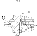
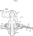
- FIG. 2 is a cross-section illustrating a fastening structure 30 according to the second exemplary embodiment. Note that members with substantially the same operation as the first exemplary embodiment are appended with the same reference numerals, and detailed explanation (including operation) thereof is omitted.
- a plate-shaped resin member 32 overlaps the plate-shaped metal member 12.
- a circular-shaped through-hole 32A serving as a second through-hole and set with a larger diameter than the through-hole 12A formed in the metal member 12, is formed in the resin member 32.
- a tube portion 36 provided to a collar 34 made of metal, is capable of being inserted inside the through-hole 32A.
- a through-hole 36A serving as a third through-hole, is formed in the tube portion 36.
- a shaft portion 40A of a flange bolt 40 serving as a fastener, is inserted through the through-hole 36A.
- a circular plate-shaped flange portion 38 juts out toward the outside of the tube portion 36 from an upper end portion of the tube portion 36.
- the flange portion 38 is disposed facing an upper face 32B of the resin member 32.
- a lower face 40B1 of a head portion 40B of the flange bolt 40 is capable of abutting an upper face 38A of the flange portion 38.
- a depressed portion 42 is provided to the upper face 38A of the flange portion 38, further to the outside than an outer peripheral face 36B of the tube portion 36, and is formed a step lower than the upper face 38A of the flange portion 38.
- a projection portion 44 that projects out toward the resin member 32 side at an outer edge portion of the flange portion 38 is continuously formed along the circumferential direction around the through-hole 32A of the resin member 32 at a lower face 38C of the flange portion 38.
- a leading end side of the projection portion 44 forms a shape projecting toward the resin member 32 side, and a leading end portion of the projection portion 44 is curved.
- a cross-section profile of the projection portion 44 sectioned along the up-down direction may be formed in a semicircular shape, a triangular shape, a trapezoidal shape, or the like.
- Substantially tube-shaped sealing rubber 46 serving as an elastic member, is integrally molded to the collar 34 so as to cover the depressed portion 42 of the flange portion 38, an outer peripheral face 38B serving as an outside face of the flange portion 38, and the lower face 38C of the flange portion 38.
- the sealing rubber 46 extends from the outer peripheral face 38B of the flange portion 38 of the collar 34 as far as a region facing (contacting) the head portion 40B of the flange bolt 40.
- an upper face 46A of the sealing rubber 46 is set so as not to be lower than the upper face 38A of the flange portion 38. Namely, the upper face 46A of the sealing rubber 46 is set so as to reliably abut the lower face 40B1 of the head portion 40B of the flange bolt 40.
- a press-contact portion 48 that projects out toward the resin member 32 side is continuously formed along the circumferential direction around the through-hole 32A of the resin member 32 at an outer edge portion of the sealing rubber 46.
- the press-contact portion 48 is formed in a position overlapping the projection portion 44 formed on the flange portion 38 of the collar 34, as viewed from the direction in which the fastening force of the flange bolt 40 and the weld nut 26 acts.
- a leading end side of the press-contact portion 48 forms a bulge-shape bulging toward the resin member 32 side, and a leading end portion of the press-contact portion 48 is curved.
- a cross-section profile of the press-contact portion 48 sectioned along the up-down direction may be formed in a semicircular shape, a triangular shape, a trapezoidal shape, or the like, and the shape of the press-contact portion 48 is not necessarily the same as the shape of the projection portion 44.
- a portion of the press-contact portion 48 is pressed against the upper face 32B of the resin member 32 by the fastening force of the flange bolt 40 and the weld nut 26, and undergoes elastic deformation. Namely, the press-contact portion 48 undergoes elastic deformation in a state in which the resin member 32 has been fastened to the metal member 12 by the flange bolt 40 and the weld nut 26, and is elastically press-contacted against the resin member 32.
- the sealing rubber 46 provided to the collar 34 is thereby press-contacted against the resin member 32, and the press-contact portion 48 of the sealing rubber 46 is elastically press-contacted against the resin member 32, by the fastening force due to the flange bolt 40 and the weld nut 26.
- the sealing performance between the metal member 12 and the resin member 32 is improved by the press-contact force of the sealing rubber 24 in this manner.
- the press-contact portion 48 of the sealing rubber 46 is elastically press-contacted against the resin member 32, thereby enabling relative movement between the collar 34 and the resin member 32 to be restricted by the flange bolt 40 and the weld nut 26 in the shear direction orthogonal to the fastening direction.
- the depressed portion 42 of the flange portion 38 of the collar 34, the outer peripheral face 38B serving as the outside face of the flange portion 38, and the lower face 38C of the flange portion 38 are covered by the sealing rubber 24.
- the outer peripheral face 38B of the flange portion 38 is covered in a state in which the sealing rubber 24 wraps around an edge portion 38C1 of the lower face 38C of the flange portion 38.
- the fastening structure 30 of the present exemplary embodiment thereby enables water, dust, and the like to be suppressed or prevented from entering between the collar 34 and the resin member 32, compared to, for example, a case in which only a lower face of a flange portion is covered by sealing rubber, not illustrated in the drawings.
- the sealing rubber 46 extends from the outer peripheral face 38B of the flange portion 38 of the collar 34 as far as a region facing the head portion 40B of the flange bolt 40, such that the sealing rubber 46 is also provided between the flange portion 38 and the head portion 40B of the flange bolt 40. This enables water, dust, and the like to also be suppressed or prevented from entering between the collar 34 and the flange bolt 40.
- the press-contact portion 48 of the sealing rubber 46 is set so as to be elastically press-contacted against the resin member 32. This enables rattling about between the resin member 32 and the collar 34 to be suppressed or prevented, even when the plate thickness of the resin member 32 has decreased due to creep deformation.
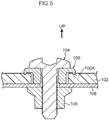
- a protruding portion 100A that abuts a fiber reinforced plastic 102 is provided to a collar 100 made of metal.
- the protruding portion 100A is made to dig into the fiber reinforced plastic 102 by fastening force due to a flange bolt 104 and a weld nut 106, since the fiber reinforced plastic 102 has a high strength, the protruding portion 100A sometimes does not dig into the fiber reinforced plastic 102.
- Electro-deposition (ED) coating (electrolytic corrosion coating) is applied in advance to the surfaces of the collar 100 and a metal member 108 in order to prevent corrosion; however, there is a possibility of this ED coating flaking off when attempting to make the protruding portion 100A dig into the fiber reinforced plastic 102 with undue force. In such cases, there is a possibility of galvanic corrosion (electrolytic corrosion) occurring due to the contact between the fiber reinforced plastic 102 and the collar 100.
- ED Electro-deposition
- the sealing rubber 46 is provided between the collar 34 made of metal and the resin member 32, such that there is no direct contact between the collar 34 and the resin member 32.
- the issue of electrolytic corrosion does not arise in the present exemplary embodiment.
- the projection portion 44 formed on the flange portion 38 of the collar 34 and the press-contact portion 48 formed on the sealing rubber 46 are formed in positions overlapping each other, as viewed from the direction in which the fastening force due to the flange bolt 40 and the weld nut 26 acts. This enables the sealing rubber 46 to be pressed against the resin member 32 by the projection portion 44 of the collar 34. The press-contact force against the resin member 32 by the press-contact portion 48 formed on the sealing rubber 46 is thereby increased.
Landscapes
- Engineering & Computer Science (AREA)
- General Engineering & Computer Science (AREA)
- Mechanical Engineering (AREA)
- Bolts, Nuts, And Washers (AREA)
- Connection Of Plates (AREA)
- Gasket Seals (AREA)
Claims (8)
- Befestigungsstruktur mit:einem plattenförmigen Metallbauteil (12), das mit einem ersten Durchgangsloch (12A) ausgebildet ist, durch das eine Befestigung eingeführt ist;einem plattenförmigen Harzbauteil (32), welches das Metallbauteil (12) überlappt, das mit einem zweiten Durchgangsloch (32A), dessen Durchmesser größer als der des ersten Durchgangsloches (12A) ist, ausgebildet ist und mit dem Metallbauteil (12) über die Befestigung befestigt ist;einem Kragen (34), der aus Metall hergestellt ist und einen röhrenförmigen Abschnitt (36), der in das zweite Durchgangsloch (32A) eingeführt ist und mit einem dritten Durchgangsloch (36A) ausgebildet ist, durch die die Befestigung eingeführt ist, und einen Flanschabschnitt (38), der in einem Zustand, in dem der röhrenförmige Abschnitt (36) durch die zweite Durchgangsbohrung (32A) eingeführt wurde, dem Harzbauteil (32) gegenüber liegt, aufweist; undeinem elastischen Bauteil (46), welches integral mit dem Kragen (34) vorgesehen ist, zwischen dem Flanschabschnitt (38) und dem Harzbauteil (32) angeordnet ist und das Außenumfangsfläche (38B) des Flanschabschnitts (38) und eine untere Seite (38C), die eine Seite des Flanschabschnitts (38) ist, die dem Harzbauteil (32) gegenüberliegt, bedeckt,dadurch gekennzeichnet, dassan dem elastischen Bauteil (46) ein Presskontaktabschnitt (48) vorgesehen ist, der zu einer Seite des Harzbauteils (32) hervorsteht und in einem Zustand, in dem das Harzbauteil (32) durch die Befestigung an dem Metallbauteil (12) befestigt wurde, gegen das Harzbauteil drückt;an dem Kragen (34) ein Vorsprungabschnitt (44) an der unteren Seite (38C) des Flanschabschnitts (38) ausgebildet ist, der an einer Position des Flanschabschnitts (38), der dem Harzbauteil (32) gegenüber liegt, zu einer Seite des Harzbauteiles (32) vorspringt und der einen Führungsendabschnitt hat, der zu einer wulstförmigen Ausbuchtung, die zu einer Seite des Harzbauteils (32) zugewandt ist, geformt ist; undder Presskontaktabschnitt (48) und der Vorsprungabschnitt (44) an Positionen vorgesehen sind, die sich aus einer Richtung, in der die Befestigungskraft durch die Befestigung wirkt, betrachtet überlappen.
- Befestigungsstruktur nach Anspruch 1, wobei an dem elastischen Bauteil (46) der Presskontaktabschnitt (48), der gegen das Harzbauteil (32), in einem Zustand, in dem das Harzbauteil (32) an dem Metallbauteil (12) durch die Befestigung befestigt wurde, gepresst ist, kontinuierlich um die zweite Durchgangsbohrung (32A) herumgeformt ist.
- Befestigungsstruktur nach Anspruch 1, wobei an dem elastischen Bauteil (46) der Presskontaktabschnitt (48), der gegen das Harzbauteil (32), in einem Zustand, in dem das Harzbauteil (32) an dem Metallbauteil (12) durch die Befestigung befestigt wurde, gepresst ist, diskontinuierlich um die zweite Durchgangsbohrung (32A) herumgeformt ist.
- Befestigungsstruktur nach einem der Ansprüche 1 bis 3, wobei an dem Kragen (34) der Vorsprungabschnitt (44), der an einer Position des Flanschabschnitts (38), der dem Harzbauteil (32) gegenüber liegt, zu einer Seite des Harzbauteils (32) vorspringt, kontinuierlich um die zweite Durchgangsbohrung (32A) herumgeformt ist.
- Befestigungsstruktur nach einem der Ansprüche 1 bis 3, wobei an dem Kragen (34) der Vorsprungabschnitt (44), der an einer Position des Flanschabschnitts (38), der dem Harzbauteil (32) gegenüber liegt, zu einer Seite des Harzbauteils (32) hervorsteht, diskontinuierlich um die zweite Durchgangsbohrung (32A) herumgeformt ist.
- Befestigungsstruktur nach einem der Ansprüche 1 bis 5, wobei sich das elastische Bauteil (46) um die Außenseite des Flanschabschnitts (38) herumwickelt und sich bis zu einem Bereich erstreckt, der die Befestigung berührt.
- Befestigungsstruktur nach einem der Ansprüche 1 bis 5, wobei das elastische Bauteil (46) am Kragen (34) einstückig ausgebildet ist.
- Befestigungsstruktur nach Anspruch 6, wobei
ein eingedrückter Bereich (42), der als eine Stufe unterhalb einer Oberfläche (38A) des Flanschabschnitts (38) geformt ist, weiter außenliegend als eine äußere Umfangsfläche des röhrenförmigen Abschnitts (36) an der oberen Seite (38A) des Flanschabschnitts (38) vorgesehen ist; und
der eingedrückte Bereich (42) des Flanschabschnitts (38), die äußere Umlauffläche des Flanschabschnitts (38) und die Unterseite (38C) des Flanschabschnitts (38) durch das elastische Bauteil (46) bedeckt sind.
Applications Claiming Priority (3)
| Application Number | Priority Date | Filing Date | Title |
|---|---|---|---|
| JP2013242238 | 2013-11-22 | ||
| JP2014181424A JP6156294B2 (ja) | 2013-11-22 | 2014-09-05 | 締結構造 |
| PCT/JP2014/080536 WO2015076270A1 (ja) | 2013-11-22 | 2014-11-18 | 締結構造 |
Publications (3)
| Publication Number | Publication Date |
|---|---|
| EP3073128A1 EP3073128A1 (de) | 2016-09-28 |
| EP3073128A4 EP3073128A4 (de) | 2016-12-07 |
| EP3073128B1 true EP3073128B1 (de) | 2019-04-10 |
Family
ID=53179531
Family Applications (1)
| Application Number | Title | Priority Date | Filing Date |
|---|---|---|---|
| EP14864873.6A Not-in-force EP3073128B1 (de) | 2013-11-22 | 2014-11-18 | Befestigungsstruktur |
Country Status (5)
| Country | Link |
|---|---|
| US (1) | US9746021B2 (de) |
| EP (1) | EP3073128B1 (de) |
| JP (1) | JP6156294B2 (de) |
| CN (1) | CN105765238B (de) |
| WO (1) | WO2015076270A1 (de) |
Families Citing this family (22)
| Publication number | Priority date | Publication date | Assignee | Title |
|---|---|---|---|---|
| JP6884497B2 (ja) * | 2014-11-13 | 2021-06-09 | 三菱重工サーマルシステムズ株式会社 | モータロータおよびそれを用いたモータ並びに電動圧縮機 |
| JP6508962B2 (ja) * | 2015-02-13 | 2019-05-08 | 株式会社青山製作所 | 樹脂板へのボルトの締結構造 |
| EP3211720A1 (de) * | 2016-02-29 | 2017-08-30 | Dubuis et Cie | Erdungsbindungsdichtung |
| US10184503B2 (en) * | 2016-03-18 | 2019-01-22 | Toyota Jidosha Kabushiki Kaisha | Fastening structure |
| JP6818425B2 (ja) * | 2016-04-19 | 2021-01-20 | 日産自動車株式会社 | 繊維強化樹脂材の締結構造 |
| JP6776635B2 (ja) * | 2016-06-07 | 2020-10-28 | トヨタ自動車株式会社 | 樹脂部材の締結部材固定構造 |
| DE102016110754A1 (de) * | 2016-06-10 | 2017-12-14 | Huf Hülsbeck & Fürst Gmbh & Co. Kg | Befestigungsvorrichtung zum Befestigen eines ersten Bauteils an einem zweiten Bauteil |
| KR102633072B1 (ko) * | 2016-09-20 | 2024-02-02 | 한국단자공업 주식회사 | 고전압 커넥터용 부시 |
| US10003113B1 (en) * | 2016-12-19 | 2018-06-19 | Ford Global Technologies, Llc | Fastening assembly and method |
| JP6870345B2 (ja) * | 2017-01-30 | 2021-05-12 | 株式会社アイシン | 吸気装置の取付構造、吸気装置の取付方法および樹脂部材の締結構造 |
| JP6820239B2 (ja) * | 2017-06-22 | 2021-01-27 | 株式会社ブリヂストン | 防振装置用ブラケット |
| JP7132564B2 (ja) * | 2018-04-10 | 2022-09-07 | 株式会社板野紙工 | ダンボール製マネキン |
| JP6973271B2 (ja) | 2018-04-26 | 2021-11-24 | トヨタ自動車株式会社 | プロテクタ及びプロテクタ製造方法 |
| US11339823B2 (en) * | 2018-08-09 | 2022-05-24 | J.S.T. Corporation | System and method for sealing a metal fastener from electrolyte in an area of dissimilar metals |
| JP7093701B2 (ja) * | 2018-08-31 | 2022-06-30 | 本田技研工業株式会社 | 繊維強化樹脂成形品 |
| US12098771B2 (en) * | 2018-09-05 | 2024-09-24 | Nok Corporation | Coupling device and sealing device |
| US10819073B2 (en) | 2018-12-04 | 2020-10-27 | J.S.T. Corporation | High voltage connector and method for assembling thereof |
| US11476530B2 (en) | 2020-03-10 | 2022-10-18 | Karma Automotive Llc | Vehicle battery assembly |
| JP6797323B1 (ja) | 2020-03-31 | 2020-12-09 | 株式会社トープラ | ねじ締結具 |
| DE102020207094A1 (de) | 2020-06-05 | 2021-12-09 | Volkswagen Aktiengesellschaft | Anordnung zweier Dichtpartner |
| JP7072698B1 (ja) * | 2021-03-26 | 2022-05-20 | 三菱電機株式会社 | 降圧コンバータ |
| JP2023141256A (ja) * | 2022-03-23 | 2023-10-05 | いすゞ自動車株式会社 | 樹脂部材の取付構造 |
Family Cites Families (35)
| Publication number | Priority date | Publication date | Assignee | Title |
|---|---|---|---|---|
| US2132636A (en) * | 1937-03-30 | 1938-10-11 | Johns Manville | Pipe assembly |
| US2982573A (en) * | 1958-12-12 | 1961-05-02 | Jr John R Mckee | Composite sealing washer |
| US3286577A (en) * | 1964-05-13 | 1966-11-22 | Atlas Bolt And Screw Company | Shouldered washer and fastening element |
| US3500712A (en) * | 1968-07-11 | 1970-03-17 | Illinois Tool Works | Sealing washer unit |
| US3661046A (en) * | 1970-11-09 | 1972-05-09 | Illinois Tool Works | Combination screw |
| US3783734A (en) * | 1972-08-28 | 1974-01-08 | Federal Screw Works | Clamp load indicating and sealing fastener assembly |
| US4175756A (en) * | 1977-02-14 | 1979-11-27 | Garlock Inc. | Combination thrust washer and seal article, apparatus |
| US4238165A (en) * | 1979-01-25 | 1980-12-09 | Illinois Tool Works Inc. | Fastener unit for clamping plastic workpieces |
| JPS6089402U (ja) | 1983-11-28 | 1985-06-19 | スズキ株式会社 | 部材の浮動締着装置 |
| US4732519A (en) * | 1986-12-24 | 1988-03-22 | Illinois Tool Works Inc. | Fastener assembly with axial play |
| US4863329A (en) * | 1988-01-29 | 1989-09-05 | United Technologies Corporation | Resiliently clamped support |
| JPH0240106U (de) * | 1988-09-12 | 1990-03-19 | ||
| JPH07729Y2 (ja) * | 1990-04-23 | 1995-01-11 | 矢崎総業株式会社 | ねじ締め型コネクタハウジング用防水リング |
| US5244325A (en) * | 1992-09-28 | 1993-09-14 | Elco Industries, Inc. | Fastener assembly with axially slidable sleeve |
| US6044536A (en) * | 1995-12-23 | 2000-04-04 | Richard Bergner Gmbh & Co. | Method for making an assembly unit |
| US6059503A (en) * | 1998-10-27 | 2000-05-09 | Johnson; H. Thad | Captivated fastener assembly |
| JP3490927B2 (ja) * | 1999-05-19 | 2004-01-26 | ニチアス株式会社 | 熱遮蔽板に振動フローティングワッシャを取付ける方法 |
| JP4056209B2 (ja) * | 2000-02-29 | 2008-03-05 | 株式会社カナイ | 木やせ対応金物と木やせ対応締め付け用金物 |
| JP2001263314A (ja) * | 2000-03-17 | 2001-09-26 | Honda Motor Co Ltd | マグネシウム合金部材のボルト締結構造 |
| DE20008684U1 (de) * | 2000-05-13 | 2001-09-20 | fischerwerke Artur Fischer GmbH & Co. KG, 72178 Waldachtal | Befestigungselement für ein Mehrscheibenglas und Anordnung in dem in einem plattenförmigen Mehrschichtkörper verankerten Befestigungselement |
| DE10104672B4 (de) * | 2001-02-02 | 2004-04-15 | Kamax-Werke Rudolf Kellermann Gmbh & Co. Kg | Montageeinheit aus einem Bauteil und mindestens einer Schraube |
| US7086688B2 (en) * | 2003-09-16 | 2006-08-08 | Honda Motor Company, Ltd. | Fastening system with bearing member |
| ITTO20040147A1 (it) * | 2004-03-09 | 2004-06-09 | Cnh Italia Spa | Dispositivo di fissaggio con soppressione del rumore in particolare per fissare reciprocamente due componenti soggetti a vibrazioni |
| NZ537537A (en) * | 2004-12-24 | 2008-03-28 | Dale Michael Mcintyre | Sanitary washer having peripheral annular rebate on upper and lower faces filled with flexible medium |
| JP2007263300A (ja) | 2006-03-29 | 2007-10-11 | Toyota Motor Corp | 樹脂部材の締結構造、ならびに樹脂部材の製造方法 |
| US20100251661A1 (en) * | 2007-06-04 | 2010-10-07 | Societa' Bulloneria Europea S.B.E.S.P.A. | Structural fixing system with high clamping force and tightening precision with high corrosion resistance |
| JP2008304023A (ja) | 2007-06-11 | 2008-12-18 | Yazaki Corp | 合成樹脂部品の取付構造 |
| JP4895046B2 (ja) * | 2007-10-02 | 2012-03-14 | 公益財団法人鉄道総合技術研究所 | セル構造多孔質金属材の設置構造 |
| KR101685957B1 (ko) * | 2009-03-04 | 2016-12-28 | 일리노이즈 툴 워크스 인코포레이티드 | 부싱 조립체 |
| JP5625260B2 (ja) | 2009-04-21 | 2014-11-19 | 株式会社豊田自動織機 | 繊維強化複合材及び繊維強化複合材の締結構造 |
| US9709171B2 (en) * | 2010-10-04 | 2017-07-18 | Bridgeport Fittings, Inc. | Sealing reducing washer |
| JP5647888B2 (ja) * | 2010-12-27 | 2015-01-07 | 東レ株式会社 | 樹脂部材の締結構造 |
| DE102011001052A1 (de) * | 2011-03-03 | 2012-09-06 | Böllhoff Verbindungstechnik GmbH | Befestigungseinrichtung mit Toleranzausgleich |
| JP2012251583A (ja) * | 2011-06-01 | 2012-12-20 | Toyota Motor Corp | 部品締結構造 |
| JP5885248B2 (ja) | 2012-04-18 | 2016-03-15 | トヨタ自動車株式会社 | 樹脂部材の締結構造 |
-
2014
- 2014-09-05 JP JP2014181424A patent/JP6156294B2/ja not_active Expired - Fee Related
- 2014-11-18 WO PCT/JP2014/080536 patent/WO2015076270A1/ja not_active Ceased
- 2014-11-18 CN CN201480063417.0A patent/CN105765238B/zh not_active Expired - Fee Related
- 2014-11-18 EP EP14864873.6A patent/EP3073128B1/de not_active Not-in-force
- 2014-11-18 US US15/037,134 patent/US9746021B2/en not_active Expired - Fee Related
Non-Patent Citations (1)
| Title |
|---|
| None * |
Also Published As
| Publication number | Publication date |
|---|---|
| JP2015121316A (ja) | 2015-07-02 |
| CN105765238A (zh) | 2016-07-13 |
| JP6156294B2 (ja) | 2017-07-05 |
| US9746021B2 (en) | 2017-08-29 |
| US20160305466A1 (en) | 2016-10-20 |
| CN105765238B (zh) | 2018-02-27 |
| WO2015076270A1 (ja) | 2015-05-28 |
| EP3073128A1 (de) | 2016-09-28 |
| EP3073128A4 (de) | 2016-12-07 |
Similar Documents
| Publication | Publication Date | Title |
|---|---|---|
| EP3073128B1 (de) | Befestigungsstruktur | |
| CN104541423B (zh) | 索环 | |
| CN103650274B (zh) | 线束的末端防水结构 | |
| JP6168828B2 (ja) | 自動車のウエザーストリップ | |
| US10946735B2 (en) | Belt assembly for vehicle having hook and swing attachment and associated method | |
| AU2010349598A1 (en) | Grommet for wire harness | |
| US20210197739A1 (en) | Clamp for wire harness | |
| WO2014061122A1 (ja) | シールワッシャ付きナット | |
| US9956938B2 (en) | Vehicular pop-up hood device | |
| JP5899963B2 (ja) | 車両ドア用被覆部材 | |
| WO2022046343A1 (en) | Light-weight body mount assembly | |
| CN105790176B (zh) | 汽车线束用卡扣转接装置及汽车 | |
| JP5742573B2 (ja) | グロメット | |
| US7878544B2 (en) | Seal for steering assemblies | |
| JP2013038978A (ja) | グロメット | |
| EP4300519A1 (de) | Tülle | |
| JP6555116B2 (ja) | 車両用ドア構造 | |
| JP4846523B2 (ja) | ボルト締結構造 | |
| JP5024091B2 (ja) | グロメット取付構造 | |
| US20250207438A1 (en) | Door handle and assembly method to mitigate component tolerances | |
| JP2007290445A (ja) | 防水グロメット及び車両用リアワイパ装置 | |
| JP5152764B2 (ja) | 自動車用ウェザーストリップの取付構造 | |
| JP5724740B2 (ja) | グロメット | |
| CN111663875A (zh) | 车辆前机盖总成和车辆 | |
| JP2019088155A (ja) | グロメットおよびグロメット取付構造 |
Legal Events
| Date | Code | Title | Description |
|---|---|---|---|
| PUAI | Public reference made under article 153(3) epc to a published international application that has entered the european phase |
Free format text: ORIGINAL CODE: 0009012 |
|
| 17P | Request for examination filed |
Effective date: 20160520 |
|
| AK | Designated contracting states |
Kind code of ref document: A1 Designated state(s): AL AT BE BG CH CY CZ DE DK EE ES FI FR GB GR HR HU IE IS IT LI LT LU LV MC MK MT NL NO PL PT RO RS SE SI SK SM TR |
|
| AX | Request for extension of the european patent |
Extension state: BA ME |
|
| A4 | Supplementary search report drawn up and despatched |
Effective date: 20161108 |
|
| RIC1 | Information provided on ipc code assigned before grant |
Ipc: F16B 5/02 20060101AFI20161102BHEP Ipc: F16J 15/12 20060101ALI20161102BHEP Ipc: F16J 15/10 20060101ALI20161102BHEP Ipc: F16B 43/00 20060101ALI20161102BHEP |
|
| DAX | Request for extension of the european patent (deleted) | ||
| GRAP | Despatch of communication of intention to grant a patent |
Free format text: ORIGINAL CODE: EPIDOSNIGR1 |
|
| STAA | Information on the status of an ep patent application or granted ep patent |
Free format text: STATUS: GRANT OF PATENT IS INTENDED |
|
| INTG | Intention to grant announced |
Effective date: 20181012 |
|
| GRAS | Grant fee paid |
Free format text: ORIGINAL CODE: EPIDOSNIGR3 |
|
| GRAA | (expected) grant |
Free format text: ORIGINAL CODE: 0009210 |
|
| STAA | Information on the status of an ep patent application or granted ep patent |
Free format text: STATUS: THE PATENT HAS BEEN GRANTED |
|
| RAP1 | Party data changed (applicant data changed or rights of an application transferred) |
Owner name: TOYOTA JIDOSHA KABUSHIKI KAISHA |
|
| RIN1 | Information on inventor provided before grant (corrected) |
Inventor name: KAMIMURA, SHINYA Inventor name: KAWASHIMA, MUTSUMI Inventor name: MIZUKOSHI, MIHO Inventor name: IKEDA, KOKI Inventor name: HAYASHI, HIDETOSHI |
|
| AK | Designated contracting states |
Kind code of ref document: B1 Designated state(s): AL AT BE BG CH CY CZ DE DK EE ES FI FR GB GR HR HU IE IS IT LI LT LU LV MC MK MT NL NO PL PT RO RS SE SI SK SM TR |
|
| REG | Reference to a national code |
Ref country code: GB Ref legal event code: FG4D |
|
| REG | Reference to a national code |
Ref country code: CH Ref legal event code: EP Ref country code: AT Ref legal event code: REF Ref document number: 1119052 Country of ref document: AT Kind code of ref document: T Effective date: 20190415 |
|
| REG | Reference to a national code |
Ref country code: IE Ref legal event code: FG4D |
|
| REG | Reference to a national code |
Ref country code: DE Ref legal event code: R096 Ref document number: 602014044659 Country of ref document: DE |
|
| REG | Reference to a national code |
Ref country code: DE Ref legal event code: R084 Ref document number: 602014044659 Country of ref document: DE |
|
| REG | Reference to a national code |
Ref country code: NL Ref legal event code: MP Effective date: 20190410 |
|
| REG | Reference to a national code |
Ref country code: LT Ref legal event code: MG4D |
|
| REG | Reference to a national code |
Ref country code: AT Ref legal event code: MK05 Ref document number: 1119052 Country of ref document: AT Kind code of ref document: T Effective date: 20190410 |
|
| PG25 | Lapsed in a contracting state [announced via postgrant information from national office to epo] |
Ref country code: NL Free format text: LAPSE BECAUSE OF FAILURE TO SUBMIT A TRANSLATION OF THE DESCRIPTION OR TO PAY THE FEE WITHIN THE PRESCRIBED TIME-LIMIT Effective date: 20190410 |
|
| PG25 | Lapsed in a contracting state [announced via postgrant information from national office to epo] |
Ref country code: SE Free format text: LAPSE BECAUSE OF FAILURE TO SUBMIT A TRANSLATION OF THE DESCRIPTION OR TO PAY THE FEE WITHIN THE PRESCRIBED TIME-LIMIT Effective date: 20190410 Ref country code: HR Free format text: LAPSE BECAUSE OF FAILURE TO SUBMIT A TRANSLATION OF THE DESCRIPTION OR TO PAY THE FEE WITHIN THE PRESCRIBED TIME-LIMIT Effective date: 20190410 Ref country code: PT Free format text: LAPSE BECAUSE OF FAILURE TO SUBMIT A TRANSLATION OF THE DESCRIPTION OR TO PAY THE FEE WITHIN THE PRESCRIBED TIME-LIMIT Effective date: 20190910 Ref country code: ES Free format text: LAPSE BECAUSE OF FAILURE TO SUBMIT A TRANSLATION OF THE DESCRIPTION OR TO PAY THE FEE WITHIN THE PRESCRIBED TIME-LIMIT Effective date: 20190410 Ref country code: LT Free format text: LAPSE BECAUSE OF FAILURE TO SUBMIT A TRANSLATION OF THE DESCRIPTION OR TO PAY THE FEE WITHIN THE PRESCRIBED TIME-LIMIT Effective date: 20190410 Ref country code: NO Free format text: LAPSE BECAUSE OF FAILURE TO SUBMIT A TRANSLATION OF THE DESCRIPTION OR TO PAY THE FEE WITHIN THE PRESCRIBED TIME-LIMIT Effective date: 20190710 Ref country code: AL Free format text: LAPSE BECAUSE OF FAILURE TO SUBMIT A TRANSLATION OF THE DESCRIPTION OR TO PAY THE FEE WITHIN THE PRESCRIBED TIME-LIMIT Effective date: 20190410 Ref country code: FI Free format text: LAPSE BECAUSE OF FAILURE TO SUBMIT A TRANSLATION OF THE DESCRIPTION OR TO PAY THE FEE WITHIN THE PRESCRIBED TIME-LIMIT Effective date: 20190410 |
|
| PG25 | Lapsed in a contracting state [announced via postgrant information from national office to epo] |
Ref country code: GR Free format text: LAPSE BECAUSE OF FAILURE TO SUBMIT A TRANSLATION OF THE DESCRIPTION OR TO PAY THE FEE WITHIN THE PRESCRIBED TIME-LIMIT Effective date: 20190711 Ref country code: PL Free format text: LAPSE BECAUSE OF FAILURE TO SUBMIT A TRANSLATION OF THE DESCRIPTION OR TO PAY THE FEE WITHIN THE PRESCRIBED TIME-LIMIT Effective date: 20190410 Ref country code: BG Free format text: LAPSE BECAUSE OF FAILURE TO SUBMIT A TRANSLATION OF THE DESCRIPTION OR TO PAY THE FEE WITHIN THE PRESCRIBED TIME-LIMIT Effective date: 20190710 Ref country code: RS Free format text: LAPSE BECAUSE OF FAILURE TO SUBMIT A TRANSLATION OF THE DESCRIPTION OR TO PAY THE FEE WITHIN THE PRESCRIBED TIME-LIMIT Effective date: 20190410 Ref country code: LV Free format text: LAPSE BECAUSE OF FAILURE TO SUBMIT A TRANSLATION OF THE DESCRIPTION OR TO PAY THE FEE WITHIN THE PRESCRIBED TIME-LIMIT Effective date: 20190410 |
|
| PG25 | Lapsed in a contracting state [announced via postgrant information from national office to epo] |
Ref country code: IS Free format text: LAPSE BECAUSE OF FAILURE TO SUBMIT A TRANSLATION OF THE DESCRIPTION OR TO PAY THE FEE WITHIN THE PRESCRIBED TIME-LIMIT Effective date: 20190810 Ref country code: AT Free format text: LAPSE BECAUSE OF FAILURE TO SUBMIT A TRANSLATION OF THE DESCRIPTION OR TO PAY THE FEE WITHIN THE PRESCRIBED TIME-LIMIT Effective date: 20190410 |
|
| REG | Reference to a national code |
Ref country code: DE Ref legal event code: R097 Ref document number: 602014044659 Country of ref document: DE |
|
| PG25 | Lapsed in a contracting state [announced via postgrant information from national office to epo] |
Ref country code: DK Free format text: LAPSE BECAUSE OF FAILURE TO SUBMIT A TRANSLATION OF THE DESCRIPTION OR TO PAY THE FEE WITHIN THE PRESCRIBED TIME-LIMIT Effective date: 20190410 Ref country code: SK Free format text: LAPSE BECAUSE OF FAILURE TO SUBMIT A TRANSLATION OF THE DESCRIPTION OR TO PAY THE FEE WITHIN THE PRESCRIBED TIME-LIMIT Effective date: 20190410 Ref country code: CZ Free format text: LAPSE BECAUSE OF FAILURE TO SUBMIT A TRANSLATION OF THE DESCRIPTION OR TO PAY THE FEE WITHIN THE PRESCRIBED TIME-LIMIT Effective date: 20190410 Ref country code: RO Free format text: LAPSE BECAUSE OF FAILURE TO SUBMIT A TRANSLATION OF THE DESCRIPTION OR TO PAY THE FEE WITHIN THE PRESCRIBED TIME-LIMIT Effective date: 20190410 Ref country code: EE Free format text: LAPSE BECAUSE OF FAILURE TO SUBMIT A TRANSLATION OF THE DESCRIPTION OR TO PAY THE FEE WITHIN THE PRESCRIBED TIME-LIMIT Effective date: 20190410 |
|
| PLBE | No opposition filed within time limit |
Free format text: ORIGINAL CODE: 0009261 |
|
| STAA | Information on the status of an ep patent application or granted ep patent |
Free format text: STATUS: NO OPPOSITION FILED WITHIN TIME LIMIT |
|
| PG25 | Lapsed in a contracting state [announced via postgrant information from national office to epo] |
Ref country code: IT Free format text: LAPSE BECAUSE OF FAILURE TO SUBMIT A TRANSLATION OF THE DESCRIPTION OR TO PAY THE FEE WITHIN THE PRESCRIBED TIME-LIMIT Effective date: 20190410 Ref country code: SM Free format text: LAPSE BECAUSE OF FAILURE TO SUBMIT A TRANSLATION OF THE DESCRIPTION OR TO PAY THE FEE WITHIN THE PRESCRIBED TIME-LIMIT Effective date: 20190410 |
|
| 26N | No opposition filed |
Effective date: 20200113 |
|
| PG25 | Lapsed in a contracting state [announced via postgrant information from national office to epo] |
Ref country code: TR Free format text: LAPSE BECAUSE OF FAILURE TO SUBMIT A TRANSLATION OF THE DESCRIPTION OR TO PAY THE FEE WITHIN THE PRESCRIBED TIME-LIMIT Effective date: 20190410 |
|
| PG25 | Lapsed in a contracting state [announced via postgrant information from national office to epo] |
Ref country code: SI Free format text: LAPSE BECAUSE OF FAILURE TO SUBMIT A TRANSLATION OF THE DESCRIPTION OR TO PAY THE FEE WITHIN THE PRESCRIBED TIME-LIMIT Effective date: 20190410 |
|
| REG | Reference to a national code |
Ref country code: CH Ref legal event code: PL |
|
| PG25 | Lapsed in a contracting state [announced via postgrant information from national office to epo] |
Ref country code: LI Free format text: LAPSE BECAUSE OF NON-PAYMENT OF DUE FEES Effective date: 20191130 Ref country code: MC Free format text: LAPSE BECAUSE OF FAILURE TO SUBMIT A TRANSLATION OF THE DESCRIPTION OR TO PAY THE FEE WITHIN THE PRESCRIBED TIME-LIMIT Effective date: 20190410 Ref country code: LU Free format text: LAPSE BECAUSE OF NON-PAYMENT OF DUE FEES Effective date: 20191118 Ref country code: CH Free format text: LAPSE BECAUSE OF NON-PAYMENT OF DUE FEES Effective date: 20191130 |
|
| REG | Reference to a national code |
Ref country code: BE Ref legal event code: MM Effective date: 20191130 |
|
| GBPC | Gb: european patent ceased through non-payment of renewal fee |
Effective date: 20191118 |
|
| PG25 | Lapsed in a contracting state [announced via postgrant information from national office to epo] |
Ref country code: GB Free format text: LAPSE BECAUSE OF NON-PAYMENT OF DUE FEES Effective date: 20191118 Ref country code: IE Free format text: LAPSE BECAUSE OF NON-PAYMENT OF DUE FEES Effective date: 20191118 |
|
| PG25 | Lapsed in a contracting state [announced via postgrant information from national office to epo] |
Ref country code: BE Free format text: LAPSE BECAUSE OF NON-PAYMENT OF DUE FEES Effective date: 20191130 |
|
| PG25 | Lapsed in a contracting state [announced via postgrant information from national office to epo] |
Ref country code: CY Free format text: LAPSE BECAUSE OF FAILURE TO SUBMIT A TRANSLATION OF THE DESCRIPTION OR TO PAY THE FEE WITHIN THE PRESCRIBED TIME-LIMIT Effective date: 20190410 |
|
| PG25 | Lapsed in a contracting state [announced via postgrant information from national office to epo] |
Ref country code: HU Free format text: LAPSE BECAUSE OF FAILURE TO SUBMIT A TRANSLATION OF THE DESCRIPTION OR TO PAY THE FEE WITHIN THE PRESCRIBED TIME-LIMIT; INVALID AB INITIO Effective date: 20141118 Ref country code: MT Free format text: LAPSE BECAUSE OF FAILURE TO SUBMIT A TRANSLATION OF THE DESCRIPTION OR TO PAY THE FEE WITHIN THE PRESCRIBED TIME-LIMIT Effective date: 20190410 |
|
| PGFP | Annual fee paid to national office [announced via postgrant information from national office to epo] |
Ref country code: DE Payment date: 20210929 Year of fee payment: 8 |
|
| PGFP | Annual fee paid to national office [announced via postgrant information from national office to epo] |
Ref country code: FR Payment date: 20211018 Year of fee payment: 8 |
|
| PG25 | Lapsed in a contracting state [announced via postgrant information from national office to epo] |
Ref country code: MK Free format text: LAPSE BECAUSE OF FAILURE TO SUBMIT A TRANSLATION OF THE DESCRIPTION OR TO PAY THE FEE WITHIN THE PRESCRIBED TIME-LIMIT Effective date: 20190410 |
|
| REG | Reference to a national code |
Ref country code: DE Ref legal event code: R119 Ref document number: 602014044659 Country of ref document: DE |
|
| PG25 | Lapsed in a contracting state [announced via postgrant information from national office to epo] |
Ref country code: DE Free format text: LAPSE BECAUSE OF NON-PAYMENT OF DUE FEES Effective date: 20230601 |
|
| PG25 | Lapsed in a contracting state [announced via postgrant information from national office to epo] |
Ref country code: FR Free format text: LAPSE BECAUSE OF NON-PAYMENT OF DUE FEES Effective date: 20221130 |