EP3069423B1 - Leitungsführung - Google Patents
Leitungsführung Download PDFInfo
- Publication number
- EP3069423B1 EP3069423B1 EP14796104.9A EP14796104A EP3069423B1 EP 3069423 B1 EP3069423 B1 EP 3069423B1 EP 14796104 A EP14796104 A EP 14796104A EP 3069423 B1 EP3069423 B1 EP 3069423B1
- Authority
- EP
- European Patent Office
- Prior art keywords
- strands
- line guide
- set forth
- holder
- line
- Prior art date
- Legal status (The legal status is an assumption and is not a legal conclusion. Google has not performed a legal analysis and makes no representation as to the accuracy of the status listed.)
- Active
Links
Images


Classifications
-
- F—MECHANICAL ENGINEERING; LIGHTING; HEATING; WEAPONS; BLASTING
- F16—ENGINEERING ELEMENTS AND UNITS; GENERAL MEASURES FOR PRODUCING AND MAINTAINING EFFECTIVE FUNCTIONING OF MACHINES OR INSTALLATIONS; THERMAL INSULATION IN GENERAL
- F16G—BELTS, CABLES, OR ROPES, PREDOMINANTLY USED FOR DRIVING PURPOSES; CHAINS; FITTINGS PREDOMINANTLY USED THEREFOR
- F16G13/00—Chains
- F16G13/12—Hauling- or hoisting-chains so called ornamental chains
- F16G13/16—Hauling- or hoisting-chains so called ornamental chains with arrangements for holding electric cables, hoses, or the like
-
- H—ELECTRICITY
- H02—GENERATION; CONVERSION OR DISTRIBUTION OF ELECTRIC POWER
- H02G—INSTALLATION OF ELECTRIC CABLES OR LINES, OR OF COMBINED OPTICAL AND ELECTRIC CABLES OR LINES
- H02G11/00—Arrangements of electric cables or lines between relatively-movable parts
- H02G11/006—Arrangements of electric cables or lines between relatively-movable parts using extensible carrier for the cable, e.g. self-coiling spring
Definitions
- the invention relates generally to a cable routing for the protected routing of at least one cable, e.g. a cable, a hose or the like, between a fixed and a movable connection point.
- a cable routing for the protected routing of at least one cable, e.g. a cable, a hose or the like, between a fixed and a movable connection point.
- a cable routing can typically accommodate several cables.
- a very common example of a cable routing is the so-called energy chain. This consists of individual links, which are usually composed of individual parts.
- EP1381792B1 the applicant describes such energy supply chains with links made up of two, four and six individual parts. Such chains have proven very successful. They are robust and reliable, but they are complex to manufacture or assemble.
- DE202012010236U1 describes another example of an energy chain consisting of individual links that are connected to one another by an articulated connection. The energy chain after DE202012010236U1 is equipped with a tension rope to relieve the articulation between the links.
- the present invention does not relate to a chain made up of individual links, but rather to a line guide according to the preamble of claim 1.
- this line guide at least one longitudinal section with several segments, or the entire line guide with all segments, is made from one piece.
- Each of these segments comprises a closable holder for holding or surrounding the at least one line transversely to the longitudinal direction of the line guide.
- the line can be inserted into a receptacle of the respective segment when the holder is open and is in the receptacle when the holder is closed Holders or held in the closed position of the holder transversely to the longitudinal direction.
- the segments are connected to one another by a flexible connection in the longitudinal direction.
- WO 01/48885 A1 Another cable routing that is largely made in one piece, namely by extruding a strand, was in WO 01/48885 A1 suggested.
- a band-like supporting wall area is used as the articulated connection, which lies radially on the inside of the deflection bend.
- WO 01/48885 A1 relates to a reinforcing fiber which is provided parallel to the strand direction in the supporting wall area.
- a cable routing specifically for supplying vehicle seats is from the patent EP1138555B1 known.
- Lockable holders are provided in this one-piece line routing, ie the lines can be inserted according to the application after the line routing has been manufactured and, if necessary, can also be exchanged subsequently.
- cable routing EP1761982B1 Disadvantageous in terms of cable routing EP1761982B1 is in particular that the cable routing is made in one piece by encapsulation, injection molding or foaming of the cables. This means that it is not possible to manufacture the cable routing independently or to equip it with cables. The cable assembly is determined when the cable routing is manufactured. An on-site installation or, for example, equipment according to customer requirements is not possible. Furthermore, the repair of a single line requires the replacement of the line routing.
- a disadvantage of all previously known solutions is in particular that the neutral fiber, based on the usable receiving space, is always located radially on the outside or radially on the inside.
- the neutral fiber also called the zero line, is the area of the guide whose length does not change when bending or moving the deflection curve. This is the cross-sectional layer in which bending does not cause tensile or compressive stress. Ideally, the lines should be level with the neutral fiber of the line routing.
- An object of the present invention is therefore to propose a cable routing which achieves a favorable position of the neutral fiber and at the same time enables inexpensive production.
- the cable routing should be able to be made partially or completely from one piece and in particular for the automotive industry, e.g. be suitable for the electrical connection of an adjustable vehicle seat.
- this object is achieved in that the flexible connection between the segments comprises a first flexible strand and a second flexible strand, and in that at least one cross connector is provided between them and is produced in one piece with the strands.
- the at least one cross connector is like this executed or at least arranged in the ready-to-use arrangement of the line routing, ie in the closed position of the holder, in such a way that the two flexible strands lie to the side of the receiving space for the line (s).
- the two strands give a neutral fiber, which crosses the receiving space for the line (s).
- an imaginary area through both strands runs through or traverses the receiving space.
- the lines to be inserted will be at least approximately at the level of the neutral fiber in a ready-to-use arrangement.
- the neutral fiber or zero line is preferably specified or defined exclusively by the spatial position of the two flexible strands.
- the position determination of the flexible strands can in turn be largely or exclusively specified by the shape or shape of the cross connector (s).
- the cross connector here runs in an arch or bow shape around the longitudinal direction of the energy supply. In this way, both flexible strands come into a position to the side of the receiving space for the line (s).
- lockable holder is to be understood in the broadest sense here as a device which holds the line (s) in the direction transverse to the longitudinal direction.
- a channel-like or U-shaped section for example, is suitable lockable crossbar (similar WO98 / 40645A1 or EP1138555B1 ), a foldable or flexible bracket (similar US 3,473,769 ), or a design in the manner of a clamp, etc.
- the holder can be closed only once, like a one-way closure for one-time use, so that the cables can at least be optionally assembled. However, holders or closures that can be opened and closed several times are preferred. This enables subsequent repairs or changes to the wiring.
- a particular embodiment is one in which the two strands are located at least approximately in the middle of the side of the receiving space, at least in the closed position or operating arrangement, i.e. define a neutral fiber that crosses or crosses the receiving space approximately halfway up.
- this position corresponds to the optimal position for minimizing the loads on the line (s).
- it can be provided over several segments or over the total length of the cross connector, which is integral in the longitudinal direction, for determining the position of the strands.
- each segment has one or more separately provided cross connectors.
- material savings are possible.
- a free space is accordingly provided between two adjacent cross connections, which may also facilitate bending or folding.
- An embodiment is particularly preferred in which exactly one assigned cross connector is provided for each lockable holder.
- Each cross connector is expediently arranged or shaped at the same longitudinal position as the other components of the holder.
- the lockable parts of the holder can, however can also be arranged in a longitudinally offset manner with respect to separately provided cross connectors.
- Each segment preferably has exactly one cross connector.
- the term segment is understood here to mean a regular or periodic longitudinal section, each of which comprises one or more, in particular exactly one holder.
- the cross connectors are made at least partially or completely flexible or foldable. Accordingly, the cross connectors only assume the desired arcuate or bow-shaped course in the closed position, in particular at the level of the correspondingly closed holder.
- the cross connectors can in particular assume an arcuate shape in the case of flexible cross connectors or an approximately polygonal shape in the case of foldable cross connectors. A combination of these is also possible, e.g. if the cross connectors are made partially flexible and partially foldable.
- the line routing can initially be produced in a relatively flat arrangement. You can then, e.g. during installation, be brought into the operational shape, in particular by bending or folding. The desired lateral position of the flexible strands can thus be achieved by closing the holder, which is required anyway.
- cross connectors completely or partially rigid.
- injection mold which may be more complex, it is possible, for example, to produce a line guide with overall rigid cross-connectors, the bow-shaped course of which is more or less permanently predetermined around the longitudinal direction.
- the latter version has the advantage of further reducing the assembly effort, but may be more complex to manufacture the cable routing.
- each holder of the line guide has a mechanical closure for closing the holder.
- all suitable types of closures come into question, in particular those which are caused by snapping, snagging, locking, etc. or a combination thereof.
- the closed holder should expediently close the receiving space for the line (s), i.e. completely surround it.
- a particularly simple embodiment of a mechanical closure each has one or more snap hooks, preferably two cooperating snap hooks. These can be integrally formed on the end region of a resilient transverse extension, for example in an extension of the cross connector.
- the latter embodiment is expedient in the case of permanent shaping of the cross connectors and / or in combination with stop surfaces on the cross connectors.
- each mechanical closure has end faces on the end face.
- two longitudinal projections with frontal stop surfaces can be provided on the closure.
- Corresponding stop surfaces can in any case be provided by suitable shaping of the mechanical closure itself. They make it possible to absorb bending loads in the extended position of the cable routing and thus prevent undesired bending of the cable routing, in particular the cantilevered upper run.
- the flexible strands can be relatively flexible or with the least possible Restoring force. This enables movement (longitudinal displacement of the deflection bend) with particularly low resistance.
- each rigid cross connector has two longitudinal projections with end faces on the end face. This also absorbs bending loads in the extended position of the cable routing in order to prevent bending, in particular of the upper run.
- the parts with stop faces are in any case arranged on the outside with respect to the deflection bend.
- the longitudinal dimension between the stop surfaces is approximately the same size or slightly larger than the regular segment length in the longitudinal direction of a segment of the line routing. With a slightly larger dimension between the stop surfaces, a pretension is made possible, especially on the upper run.
- further stop surfaces with a smaller longitudinal distance can also be arranged to limit the radius of the deflection bend, i.e. depending on the position on the cross connectors or on the closures, inside with respect to the deflection bend. However, this is not necessary if the strands are sufficiently stiff or have low elasticity.
- a mechanical closure and a cross connector together or together form a holder. They preferably form a bracket-like holder, for example according to the principle of a bracket clamp or a similar holding device.
- This enables a particularly material-saving construction of the individual segments of the line routing, which essentially consists of two strand sections, one Cross connector and the components of the mechanical closure, are made.
- the closure and the cross connector are preferably in the same longitudinal position along the strands. In this case, the receiving space is the space surrounded by the holder.
- both strands run essentially parallel (i.e., technically parallel) and are at least opposite one another in the operating position or permanently.
- Separate cross connectors are each in a plane perpendicular to the longitudinal course of the strands.
- the flexible connection through the strands is preferably not flexible, but flexible, and preferably generates a certain restoring force. In this way, a predefined radius can be guaranteed in the deflection curve between the upper run and lower run.
- kinking of the line (s) can also be guaranteed without any angle-limiting stops on the segments.
- the unsupported interval length of the strands ie the longitudinal extension of the free space or the free distance between adjacent cross connectors, be at least three times, preferably at least five times the strand thickness, ie the strand diameter in the plane perpendicular to the bending axis of the deflection bend , is. It should therefore be provided that the unsupported strand length between two cross connectors is significantly greater than the strength of the strand, which mainly counteracts the bending moment on the deflection bend.
- the aforementioned measure can also be used, for example, in the case of relatively strong strand shapes or rigid strand material For high tensile forces, sufficient bending flexibility can be guaranteed with typical injection-molded plastics.
- the largest diameter of a strand is expediently also significantly smaller than the smallest diameter of the receiving space.
- the unsupported interval length of the strands is at most fifteen times, preferably at most ten times the strand thickness, ie the strand diameter in the plane perpendicular to the bending axis of the deflection bend.
- a corresponding upper limit ensures a sufficiently high bending stiffness, for example for unsupported horizontal applications. In this way, bending of the cable routing over longer, unsupported sections can be avoided, if necessary also without stop faces. In the case of a vertical arrangement, however, a high degree of flexural rigidity is usually not desired.
- the two strands are of identical cross-section and are preferably rope or band-shaped.
- the cross section of the strands can be circular, elliptical or polygonal, for example.
- a favorable position of the neutral fiber is expediently achieved if the circumferential dimension of a cross connector is sufficiently large.
- the circumferential dimension viewed in the plane perpendicular to the longitudinal direction and measured between the two strands, is in each case at least one and a half times the width of the receiving space at the height of the strands.
- this circumferential dimension is preferably in the range from 30% to 70%, preferably 40% to 60% of the total circumference of the receiving space, also considered at the level of the holder assigned to the cross connector.
- the circumferential dimension may be understood to mean the arc length of the circular arc connecting the two strands, which arises through the cross connector runs or forms the circle.
- a good fastening of the guided lines is achieved with short free spaces, i.e. if the unsupported strand length between two cross connectors is not greater than the circumferential dimension of a holder, preferably not greater than half the circumferential dimension of a holder.
- a cable routing according to the invention can be made from different materials.
- the entire line routing is particularly advantageously made in one piece from a plastic, in particular by injection molding from a technical polymer plastic.
- the line routing is made entirely or in one piece, e.g. made of a thermoplastic.
- each segment of the line routing comprises fastening means for a non-positive and / or form-fitting fastening of the end segments of the line routing.
- the cable routing can be attached to the movable carrier and to the fixed connection point using suitable counterparts.
- the fasteners could also be used to connect individual, one-piece longitudinal sections together to form a conduit of greater overall length, e.g. by means of suitable coupling pieces.
- the fasteners can be molded in particular in the injection molding process.
- a head with lateral locking grooves can be provided on each segment, in particular on each closure and / or on each cross connector.
- the line routing can be produced in a standard length and can be cut to the desired size depending on the length required, for example by separating the strands.
- they are located at the ends Segments of the cable routing always include suitable fastening means for fastening to a first, fixed connection point and to a second, movable connection point.
- the cable routing according to the invention can be produced particularly inexpensively and is therefore particularly, but not exclusively, suitable for the automotive industry.
- it can be used to connect a motor vehicle seat to electrical supply and / or signal lines, for example for seat heating, electric motors for seat adjustment, seat occupancy detection, etc.
- the invention further relates to an arrangement comprising a motor vehicle seat and at least one electrical supply and / or signal line and a line routing according to the present invention, which protects and guides the supply and / or signal line.
- a line routing according to the invention is generally designated 100.
- the cable run 100 forms an upper run 102, a lower run 104 and a movable deflection bend 106 between the upper run 102 and the lower run 104.
- the cable run 100 is made in one piece overall and comprises a multiplicity of individual segments 110, 112. Segments 110 of a first type alternate in the longitudinal direction Segments 112 of a second type.
- the end segment of the upper run 102 is attached to a separately manufactured driver 114.
- the driver 114 can e.g. is a connecting part specifically for fastening cables to a motor vehicle driver's seat (not shown here) (see FIG. 6).
- the end segment of the lower run 104 is fastened to a separate mounting plate 116.
- the mounting plate 116 serves e.g. for attachment to the vehicle floor.
- the cable guide 100 comprises two strands 120 which are produced in one piece with the individual segments 110, 112.
- the strands 120 ensure the flexible connection of the individual segments 110, 112 and are designed to be correspondingly flexible.
- the driver 114 can therefore according to the Double arrows H, V are moved horizontally or vertically relative to the mounting plate 116 and with corresponding deformation of the line guide 100.
- the cable routing 100 prevents, among other things, kinking of the cables (not shown) and, despite the freely adjustable height and longitudinal position of the driver 114, ensures safe, protected and defined routing of the supply lines, which are not shown in detail.
- FIG.2A shows a plurality of individual cross connectors 122, which are also made in one piece or in one piece with the individual strands 120.
- the cross connectors 122 thus connect the strands 120.
- the cross connectors 122 run essentially perpendicular to the longitudinal direction L or to the strands 120. They are according to the first exemplary embodiment FIG.1A-1B u.
- FIG.2A-B continuous flat ribbon with a flat, approximately rectangular cross-section.
- Each cross connector 122 is at the same time part of a holder 123.
- first and second closure parts 124a, 126a; 124b, 126b of a mechanical closure are provided, which are also components of the corresponding holder 123.
- the closure parts 124a, 126a; 124b, 126b are fastened to the strands 120 by means of tapering transverse processes and are integrally formed on the strands 120.
- First closure parts 124a, 124b and second closure parts 126a, 126b alternate in the longitudinal direction on each side of the open or flatly arranged line guide 100.
- FIG.1A-1B By bending the cross connector 122 about the longitudinal axis L and closing the holder 123 of the individual segments 110, 112, the ready-for-use arrangement is made FIG.1A-1B reached.
- the cross connectors 122 are designed as a whole or completely flexible or bendable about the longitudinal axis L and only assume an arcuate course about the longitudinal axis L when the corresponding holder 123 is closed. In the present example, the course of the cross connector 122 is approximately circular.
- exactly one cross connector 122 together with the cooperating closure parts 124a, 126a or 124b, 126b of exactly one mechanical closure form a bow-shaped holder 123 for the line (s).
- the lines are held transversely to the longitudinal direction L in a circumferentially closed receiving space 130, as from FIG.1B evident.
- the lines are inserted into the receiving space 130 with the holder 123 open and are held transversely to the longitudinal direction L in the closed position of the holder 123.
- FIG.1B and FIG.2A-2B show the structure and mode of operation of the mechanical connectors or closure parts 124a, 126a and 124b, 126b.
- the closure parts 124a, 126a of one type and the closure parts of the other type 124b, 126b are identical in function and each have a positive fit.
- the first closure part 124a, 124b has a latching edge 133 which engages behind a snap hook 135 of the second closure part 126a, 126b.
- a centering pin 134 is provided on the first closure part 124a, 124b, which fits in a recess 136 of the second closure part 126a, 126b in order to align the closure parts with one another.
- the locking parts 124a, 126a and 124b, 126b form a mechanical snap lock.
- the types of segments 110, 112 differ in the type of closure parts 124a, 126a and 124b, 126b.
- the first closure parts 124a In contrast to the other first closure parts 124b, the first closure parts 124a have end faces 140 on the end face.
- the second closure parts point in the same way 126b, in contrast to the differently shaped second closure parts 126a, end stop surfaces 140.
- the stop surfaces 140 of the first closure parts 124a interact with the stop surfaces 140 of the second closure parts 126b in order to deflect the upper strand 102 (see FIG. FIG.1A ) to prevent.
- each pair of two closed closure parts 124a, 126a and 124b, 126b forms how FIG.1A shows, a plate-shaped block, with the stop surfaces 140 as frontal boundaries in the longitudinal direction L.
- the stop surfaces 140 are perpendicular to the longitudinal direction L of the strands 120.
- the inner distance between the stop surfaces 140 (the longitudinal dimension of the closure parts 124a, 126b with stop surfaces 140 ) is set slightly larger than the regular segment length I of the segments 110, 112. In this way, a pretension is generated in the upper strand 102. This can be achieved by alternating the closure parts 124a, 124b or 126a, 126b in the longitudinal direction L even with a largely flat injection mold.
- lateral locking grooves 142 are provided on both sides of the closure parts 124a, 124b and 126a, 126b in the longitudinal direction L.
- the locking grooves 142 serve as fastening means for the segments 110, 112 in the end region.
- the locking grooves 142 act positively and non-positively together with parts on the driver 114 or on the mounting plate 116, according to the principle of a tongue and groove fastening ( FIG.1B ).
- the locking grooves 142 are provided on each of the segments 110, 112 as fastening means.
- FIG.1B The comparison of FIG.1B and FIG.2B shows that the circumferential dimension B of the cross connector 122, measured between the strands 120, is approximately 40-60% of the total circumference of the receiving space 130.
- the strands 120 lie essentially at half the height and to the side of the receiving space 130, as a result of which a particularly favorable position of the neutral fiber is achieved.
- the circumferential dimension B in the case of an elliptical or polygonal cross section of the receiving space should be at least 1.5 times the width of the receiving space 130 at the level of the neutral fiber.
- FIG.1B furthermore shows that each cross connector 122 lies in a cross-sectional plane with the two closure parts 124a, 126a or 124b, 126b, ie at approximately the same longitudinal position.
- the two strands 120 are flexible and form a deflection bend 106 with a predefined radius, without stops which limit the angle (see FIG. FIG.1A ).
- the two strands 120 have the same, identical cross section, for example according to FIG.2B , a square cross-section, whereby in the operating position FIG.1A , the lateral sides run approximately vertically or perpendicular to the axis of curvature of the deflection bend 106.
- Other cross sections of the strands 120 such as circular, elliptical, hexagonal, etc., are also conceivable.
- the ratio of the unsupported interval length F of the strands 120 between two adjacent cross connectors 122 to the strand thickness S of a strand 120 is expediently: F / S ⁇ 3, preferably F / S ⁇ 5.
- the ratio is expediently: F / S 15 15, preferably F / S 10.
- the strands 120 are in any case rope-shaped, ie with an approximately circular or square cross-section and with a longitudinal extent significantly larger than any cross-sectional diagonal.
- the strands 120 are technically parallel and are lagging behind in their design FIG.1A-1B u. 2A-2B only diametrically opposite one another with respect to the receiving space 130 in the operating position.
- exactly one separate cross connector 122 is provided in each link at regular longitudinal spacing (segment length I).
- two thinner cross connectors could also be used (see FIG.5A-5B ) provided longitudinally offset with respect to the respective mechanical closure.
- a cross connector surface with small cutouts which is virtually continuous over a few segments, is also conceivable to avoid folds in the deflection bend 106.
- the entire cable routing 100 is made in one piece, ie in one piece from an engineering plastic, for example a thermoplastic polymer.
- the line guide 100 can be produced in one piece by injection molding and, after demolding ( FIG.2A-2B ) ready for use without further processing steps.
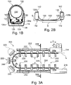
- FIG.3A-3C and FIG. 4 Show an alternative embodiment FIG.3A-3C and FIG. 4 a cable routing 200. Parts that have been raised by a hundred designate parts which in structure and / or mode of operation distinguish them FIG.1A-2B correspond. For the sake of simplicity, only the essential differences are discussed below.
- the cable routing 200 is also made in one piece by injection molding.
- the cross connectors 222 are not, however, elastic in the form of a band, but assume how FIG.3A shows the function of the block-like closures and are therefore arranged radially on the outside. Accordingly are the cross connector 222 largely rigid, with a permanently bow-shaped course around the longitudinal direction L. Consequently, stop surfaces 240 lie against the bending load on opposite, rigid longitudinal projections of the cross connector 222.
- a pretension can also be achieved in the cable guide 200, ie a longitudinal dimension of a cross connector 222 from the stop surface 240 to the stop surface 240, which is slightly larger than the regular segment length I.
- the segments 210 also each have exactly one holder 223 and one cross connector 222 on, but all segments 210 are identical.
- the holder 223 includes a closure which is in FIG.3A-3C respectively.
- FIG. 4 consists of two cooperating snap hooks 224, 226, which are made in one piece on extensions in the transverse direction together with the cross connectors 222 and the strands 220.
- the snap hooks 224, 226 lie radially on the inside with respect to the deflection bend 206. After inserting the line (s), not shown here, the snap hooks 224, 226 of the segments 210 are hooked or locked together as in FIG Neckline FIG.3C more apparent.
- the main difference is therefore that the cross connectors 222 as relatively rigid material bridges between the otherwise identical as in FIG.1A-2B designed arranged strands 220 are designed.
- the cross connectors 222 accordingly specify a permanent position of the strands 220.
- the cross connectors 222 have, due to the longitudinal projections with the stop surfaces 240, a plate-like or block-shaped head part 244. Lateral locking grooves 242 are provided on this for fastening to the driver 214 or to the mounting plate 216.
- the connection of the headboards to the strands 220 form tapered transitions, which the receiving space 230 ( FIG.3B ) give an approximately circular cross section, similar to that in FIG.2B . This minimizes wear on the line (s).
- FIG.3A only shows an end segment 210, the head part of which is fastened to catch 214 and mounting plate 216 by means of the locking grooves 242.
- a plurality of segments 210 of the end region can also be fastened, since latching grooves 242 are provided as fastening means on each segment 210.
- FIG.5A-5B show a third, particularly simple embodiment of a cable routing 300 according to the invention. Parts increased by a hundred denote parts which correspond in structure and / or mode of operation to the aforementioned.
- the cable routing 300 can also be produced as a flat structure and brought into the operational position by bending the cross connector 322 and closing the schematically shown closure parts 324, 326.
- the two strands 320 run essentially parallel and lie laterally opposite one another at half the height of the receiving space.
- two band-shaped cross connectors 322 are provided in each segment 310, so that the regular longitudinal distance F between the adjacent cross connectors 322 is less than the segment length I.
- the strands 320 are approximately band-shaped with the narrow side perpendicular to Deflection or bending axis, as in FIG.5B illustrated. Due to the simpler shape, the cable routing 300 can be manufactured more cost-effectively.
Landscapes
- Engineering & Computer Science (AREA)
- General Engineering & Computer Science (AREA)
- Mechanical Engineering (AREA)
- Electric Cable Arrangement Between Relatively Moving Parts (AREA)
- Supports For Pipes And Cables (AREA)
- Details Of Indoor Wiring (AREA)
Applications Claiming Priority (2)
| Application Number | Priority Date | Filing Date | Title |
|---|---|---|---|
| DE202013105149U DE202013105149U1 (de) | 2013-11-14 | 2013-11-14 | Leitungsführung |
| PCT/EP2014/074197 WO2015071227A1 (de) | 2013-11-14 | 2014-11-10 | Leitungsführung |
Publications (2)
| Publication Number | Publication Date |
|---|---|
| EP3069423A1 EP3069423A1 (de) | 2016-09-21 |
| EP3069423B1 true EP3069423B1 (de) | 2020-04-08 |
Family
ID=49781901
Family Applications (1)
| Application Number | Title | Priority Date | Filing Date |
|---|---|---|---|
| EP14796104.9A Active EP3069423B1 (de) | 2013-11-14 | 2014-11-10 | Leitungsführung |
Country Status (7)
| Country | Link |
|---|---|
| US (1) | US9797473B2 (enExample) |
| EP (1) | EP3069423B1 (enExample) |
| JP (1) | JP6499652B2 (enExample) |
| CN (1) | CN105900305B (enExample) |
| DE (1) | DE202013105149U1 (enExample) |
| ES (1) | ES2805375T3 (enExample) |
| WO (1) | WO2015071227A1 (enExample) |
Families Citing this family (6)
| Publication number | Priority date | Publication date | Assignee | Title |
|---|---|---|---|---|
| JP6431024B2 (ja) * | 2016-11-08 | 2018-11-28 | 矢崎総業株式会社 | 湾曲規制部材及び給電装置 |
| JP6457992B2 (ja) * | 2016-11-22 | 2019-01-23 | 矢崎総業株式会社 | 湾曲規制部材及び給電装置 |
| DE202017102410U1 (de) * | 2017-04-24 | 2017-07-31 | Igus Gmbh | System zur Lage- und/oder Leitungsüberwachung in einer Energieführungskette |
| CN106976108A (zh) * | 2017-05-26 | 2017-07-25 | 绵阳伦奇机器人有限公司 | 一种机器人三维线缆拖链滑动座 |
| SG11202108321SA (en) * | 2019-01-14 | 2021-08-30 | Igus Gmbh | Compact protective cable conduit for clean room applications and encasing unit and clamping device for same |
| EP4038710A1 (en) * | 2020-01-28 | 2022-08-10 | Hewlett-Packard Development Company L.P. | Cable carrier element |
Citations (2)
| Publication number | Priority date | Publication date | Assignee | Title |
|---|---|---|---|---|
| US5806811A (en) * | 1996-05-22 | 1998-09-15 | The Siemon Company | Wire manager for use with stand-off legs |
| WO2001048885A1 (de) * | 1999-12-23 | 2001-07-05 | Kabelschlepp Gmbh | Strang und verfahren zur herstellung eines faserverstärkten stranges einer leitungsführungsanordnung |
Family Cites Families (22)
| Publication number | Priority date | Publication date | Assignee | Title |
|---|---|---|---|---|
| US3473769A (en) | 1967-01-06 | 1969-10-21 | Ibm | Retainer for flexible leads |
| DE3531066A1 (de) | 1985-08-30 | 1987-03-12 | Igus Gmbh | Energiezufuehrungskette |
| DE3616849A1 (de) | 1986-05-16 | 1987-11-19 | Schering Ag | Pyrazolo(3,4-b)pyridinderivate, verfahren und zwischenstufen zu ihrer herstellung und ihre verwendung als mittel mit herbizider wirkung |
| DD265449B5 (de) | 1987-10-01 | 1996-11-28 | Kabelschlepp Gmbh | Kabel- und Schlauchschlepp |
| US5240209A (en) * | 1992-11-17 | 1993-08-31 | Telect, Inc. | Telecommunication multiple cable carrier |
| DE19512088C2 (de) * | 1995-04-03 | 1997-05-07 | Igus Gmbh | Energiekette |
| DE19541928C1 (de) | 1995-11-10 | 1997-06-12 | Igus Gmbh | Energieführungskette |
| CA2275926C (en) * | 1996-12-23 | 2003-12-02 | Igus Spritzgussteile Fur Die Industrie Gmbh | Energy-supply chain |
| DE19710489A1 (de) * | 1997-03-13 | 1998-09-24 | Kabelschlepp Gmbh | Faltbares Schutzelement für Leitungen |
| FR2807229B1 (fr) * | 2000-03-28 | 2002-06-28 | Peugeot Citroen Automobiles Sa | Dispositif de support et de guidage d'un faisceau de fils electriquement conducteurs permettant de suivre les deplacements d'un siege avant de vehicule automobile |
| DE20016363U1 (de) * | 2000-09-21 | 2001-01-18 | Igus Spritzgußteile für die Industrie GmbH, 51147 Köln | Energieführungskette |
| DE20107003U1 (de) | 2001-04-23 | 2002-09-19 | Igus Spritzgußteile für die Industrie GmbH, 51147 Köln | Energieführungskette |
| US6844497B2 (en) * | 2002-03-26 | 2005-01-18 | Honda Giken Kogyo Kabushiki Kaisha | Wire harness arrangement |
| DE102004025371A1 (de) | 2004-05-24 | 2005-12-22 | Leoni Bordnetz-Systeme Gmbh & Co Kg | Leitungsführungseinrichtung |
| JP2006166492A (ja) * | 2004-12-02 | 2006-06-22 | Yazaki Corp | ハーネス保護具 |
| DE102005004453A1 (de) | 2005-02-01 | 2006-08-10 | Volkswagen Ag | Krümmbarer Leitungskanal zur Aufnahme von Leitungen |
| JP4118308B2 (ja) | 2006-04-14 | 2008-07-16 | 株式会社椿本チエイン | ケーブル類保護案内装置 |
| JP2008025775A (ja) * | 2006-07-24 | 2008-02-07 | Tsubakimoto Chain Co | 折り曲げ組み立て式ケーブル類保護案内装置 |
| DE102007017940A1 (de) * | 2007-04-13 | 2008-10-16 | Igus Gmbh | Seitenwandsegment für eine Leitungsführungseinrichtung, Leitungsführungseinrichtung mit Seitenwandsegment und Verfahren zur Herstellung des Seitenwandsegmentes |
| JP4391547B2 (ja) * | 2007-04-17 | 2009-12-24 | 株式会社椿本チエイン | チューブ型ケーブル類保護案内装置 |
| DE102007041663A1 (de) * | 2007-09-03 | 2009-03-05 | Kabelschlepp Gmbh | Einrichtung zum Führen von Leitungen, Schläuchen oder dergleichen |
| DE202012010236U1 (de) | 2012-10-26 | 2012-11-23 | Igus Gmbh | Energieführungskette mit Spann- bzw. Tragvorrichtung |
-
2013
- 2013-11-14 DE DE202013105149U patent/DE202013105149U1/de not_active Expired - Lifetime
-
2014
- 2014-11-10 EP EP14796104.9A patent/EP3069423B1/de active Active
- 2014-11-10 CN CN201480072937.8A patent/CN105900305B/zh active Active
- 2014-11-10 US US15/036,931 patent/US9797473B2/en active Active
- 2014-11-10 ES ES14796104T patent/ES2805375T3/es active Active
- 2014-11-10 JP JP2016531661A patent/JP6499652B2/ja active Active
- 2014-11-10 WO PCT/EP2014/074197 patent/WO2015071227A1/de not_active Ceased
Patent Citations (2)
| Publication number | Priority date | Publication date | Assignee | Title |
|---|---|---|---|---|
| US5806811A (en) * | 1996-05-22 | 1998-09-15 | The Siemon Company | Wire manager for use with stand-off legs |
| WO2001048885A1 (de) * | 1999-12-23 | 2001-07-05 | Kabelschlepp Gmbh | Strang und verfahren zur herstellung eines faserverstärkten stranges einer leitungsführungsanordnung |
Also Published As
| Publication number | Publication date |
|---|---|
| ES2805375T3 (es) | 2021-02-11 |
| US20160348756A1 (en) | 2016-12-01 |
| CN105900305A (zh) | 2016-08-24 |
| WO2015071227A1 (de) | 2015-05-21 |
| EP3069423A1 (de) | 2016-09-21 |
| JP2016538502A (ja) | 2016-12-08 |
| US9797473B2 (en) | 2017-10-24 |
| DE202013105149U1 (de) | 2013-11-27 |
| CN105900305B (zh) | 2018-08-03 |
| JP6499652B2 (ja) | 2019-04-10 |
Similar Documents
| Publication | Publication Date | Title |
|---|---|---|
| EP3069423B1 (de) | Leitungsführung | |
| EP0966624B1 (de) | Faltbares schutzelement für leitungen | |
| DE102008015954B4 (de) | Schutz- und Führungsvorrichtung für Kabel oder Schläuche | |
| DE3837088C2 (de) | Flexibler Zugverschluß | |
| EP1108157B1 (de) | Energieführungskette zum führen von leitungen mit räumlich beweglichen kettengliedern | |
| EP0954077A2 (de) | Rohranordnung | |
| EP3568610B1 (de) | Trennsteg für energieführungsketten | |
| EP3123581B1 (de) | Leitungsführungseinrichtung mit einstückigem gelenk und entsprechendes kettenglied | |
| EP3271612B1 (de) | Energieführungskette mit halter für eine externe leitung, aufnahmeelement und entsprechende seitenlasche | |
| EP3020107B1 (de) | Einrichtung zur fixierung und/oder führung von strangförmigen elementen | |
| EP4169131B1 (de) | Steckverbinder umfassend einen kontaktträger mit zwei benachbarten haltestegen | |
| DE202019100877U1 (de) | Endbefestigungsteil für eine Energieführungskette | |
| EP3924642B1 (de) | Mehrteiliges kettenglied einer energieführungskette sowie quersteg und seitenlasche hierfür | |
| EP3894720B1 (de) | Betriebsfest ausgelegte seitenlasche für eine energieführungskette | |
| DE102014226334A1 (de) | Kabelführungsvorrichtung sowie Verfahren zur Herstellung einer solchen Kabelführungsvorrichtung | |
| EP3740399B1 (de) | Klemme und fahrdrahtträgeranordnung | |
| DE102008047323B4 (de) | Schutz-und Führungsvorrichtung für ein Kabel oder einen Schlauch | |
| EP1816373A2 (de) | Energieführungskette | |
| EP2653325B1 (de) | Vorrichtung zum Anbinden des Laufnetzes einer Schneekette | |
| EP4033120B1 (de) | Befestigungsvorrichtung zur befestigung mindestens eines kettenstrangs an einem haltemittel | |
| EP2901882B1 (de) | Blockierbare Gurtzunge für einen Dreipunkt-Sicherheitsgurt | |
| EP4139586B1 (de) | Leitungsführungseinrichtung, insbesondere energieführungskette, und kettenglied mit dämpfungselementen | |
| WO2009149697A1 (de) | Profilschienenhalteelement und dafür geeignete mutter | |
| EP1460214B1 (de) | Aus Kunststoff bestehendes Stangenverschlusssystem | |
| EP1614553B1 (de) | Durchziehöse für die Spannkette einer Gleitschutzkette |
Legal Events
| Date | Code | Title | Description |
|---|---|---|---|
| PUAI | Public reference made under article 153(3) epc to a published international application that has entered the european phase |
Free format text: ORIGINAL CODE: 0009012 |
|
| 17P | Request for examination filed |
Effective date: 20160530 |
|
| AK | Designated contracting states |
Kind code of ref document: A1 Designated state(s): AL AT BE BG CH CY CZ DE DK EE ES FI FR GB GR HR HU IE IS IT LI LT LU LV MC MK MT NL NO PL PT RO RS SE SI SK SM TR |
|
| AX | Request for extension of the european patent |
Extension state: BA ME |
|
| DAX | Request for extension of the european patent (deleted) | ||
| STAA | Information on the status of an ep patent application or granted ep patent |
Free format text: STATUS: EXAMINATION IS IN PROGRESS |
|
| 17Q | First examination report despatched |
Effective date: 20170511 |
|
| GRAP | Despatch of communication of intention to grant a patent |
Free format text: ORIGINAL CODE: EPIDOSNIGR1 |
|
| STAA | Information on the status of an ep patent application or granted ep patent |
Free format text: STATUS: GRANT OF PATENT IS INTENDED |
|
| INTG | Intention to grant announced |
Effective date: 20191024 |
|
| GRAS | Grant fee paid |
Free format text: ORIGINAL CODE: EPIDOSNIGR3 |
|
| GRAA | (expected) grant |
Free format text: ORIGINAL CODE: 0009210 |
|
| STAA | Information on the status of an ep patent application or granted ep patent |
Free format text: STATUS: THE PATENT HAS BEEN GRANTED |
|
| AK | Designated contracting states |
Kind code of ref document: B1 Designated state(s): AL AT BE BG CH CY CZ DE DK EE ES FI FR GB GR HR HU IE IS IT LI LT LU LV MC MK MT NL NO PL PT RO RS SE SI SK SM TR |
|
| REG | Reference to a national code |
Ref country code: CH Ref legal event code: EP Ref country code: AT Ref legal event code: REF Ref document number: 1255643 Country of ref document: AT Kind code of ref document: T Effective date: 20200415 |
|
| REG | Reference to a national code |
Ref country code: DE Ref legal event code: R096 Ref document number: 502014013956 Country of ref document: DE |
|
| REG | Reference to a national code |
Ref country code: IE Ref legal event code: FG4D Free format text: LANGUAGE OF EP DOCUMENT: GERMAN |
|
| REG | Reference to a national code |
Ref country code: CH Ref legal event code: NV Representative=s name: KATZAROV SA, CH |
|
| REG | Reference to a national code |
Ref country code: NL Ref legal event code: MP Effective date: 20200408 |
|
| REG | Reference to a national code |
Ref country code: LT Ref legal event code: MG4D |
|
| PG25 | Lapsed in a contracting state [announced via postgrant information from national office to epo] |
Ref country code: FI Free format text: LAPSE BECAUSE OF FAILURE TO SUBMIT A TRANSLATION OF THE DESCRIPTION OR TO PAY THE FEE WITHIN THE PRESCRIBED TIME-LIMIT Effective date: 20200408 Ref country code: LT Free format text: LAPSE BECAUSE OF FAILURE TO SUBMIT A TRANSLATION OF THE DESCRIPTION OR TO PAY THE FEE WITHIN THE PRESCRIBED TIME-LIMIT Effective date: 20200408 Ref country code: SE Free format text: LAPSE BECAUSE OF FAILURE TO SUBMIT A TRANSLATION OF THE DESCRIPTION OR TO PAY THE FEE WITHIN THE PRESCRIBED TIME-LIMIT Effective date: 20200408 Ref country code: IS Free format text: LAPSE BECAUSE OF FAILURE TO SUBMIT A TRANSLATION OF THE DESCRIPTION OR TO PAY THE FEE WITHIN THE PRESCRIBED TIME-LIMIT Effective date: 20200808 Ref country code: PT Free format text: LAPSE BECAUSE OF FAILURE TO SUBMIT A TRANSLATION OF THE DESCRIPTION OR TO PAY THE FEE WITHIN THE PRESCRIBED TIME-LIMIT Effective date: 20200817 Ref country code: NO Free format text: LAPSE BECAUSE OF FAILURE TO SUBMIT A TRANSLATION OF THE DESCRIPTION OR TO PAY THE FEE WITHIN THE PRESCRIBED TIME-LIMIT Effective date: 20200708 Ref country code: GR Free format text: LAPSE BECAUSE OF FAILURE TO SUBMIT A TRANSLATION OF THE DESCRIPTION OR TO PAY THE FEE WITHIN THE PRESCRIBED TIME-LIMIT Effective date: 20200709 Ref country code: NL Free format text: LAPSE BECAUSE OF FAILURE TO SUBMIT A TRANSLATION OF THE DESCRIPTION OR TO PAY THE FEE WITHIN THE PRESCRIBED TIME-LIMIT Effective date: 20200408 |
|
| PG25 | Lapsed in a contracting state [announced via postgrant information from national office to epo] |
Ref country code: HR Free format text: LAPSE BECAUSE OF FAILURE TO SUBMIT A TRANSLATION OF THE DESCRIPTION OR TO PAY THE FEE WITHIN THE PRESCRIBED TIME-LIMIT Effective date: 20200408 Ref country code: RS Free format text: LAPSE BECAUSE OF FAILURE TO SUBMIT A TRANSLATION OF THE DESCRIPTION OR TO PAY THE FEE WITHIN THE PRESCRIBED TIME-LIMIT Effective date: 20200408 Ref country code: LV Free format text: LAPSE BECAUSE OF FAILURE TO SUBMIT A TRANSLATION OF THE DESCRIPTION OR TO PAY THE FEE WITHIN THE PRESCRIBED TIME-LIMIT Effective date: 20200408 Ref country code: BG Free format text: LAPSE BECAUSE OF FAILURE TO SUBMIT A TRANSLATION OF THE DESCRIPTION OR TO PAY THE FEE WITHIN THE PRESCRIBED TIME-LIMIT Effective date: 20200708 |
|
| PG25 | Lapsed in a contracting state [announced via postgrant information from national office to epo] |
Ref country code: AL Free format text: LAPSE BECAUSE OF FAILURE TO SUBMIT A TRANSLATION OF THE DESCRIPTION OR TO PAY THE FEE WITHIN THE PRESCRIBED TIME-LIMIT Effective date: 20200408 |
|
| REG | Reference to a national code |
Ref country code: DE Ref legal event code: R097 Ref document number: 502014013956 Country of ref document: DE |
|
| PG25 | Lapsed in a contracting state [announced via postgrant information from national office to epo] |
Ref country code: SM Free format text: LAPSE BECAUSE OF FAILURE TO SUBMIT A TRANSLATION OF THE DESCRIPTION OR TO PAY THE FEE WITHIN THE PRESCRIBED TIME-LIMIT Effective date: 20200408 Ref country code: EE Free format text: LAPSE BECAUSE OF FAILURE TO SUBMIT A TRANSLATION OF THE DESCRIPTION OR TO PAY THE FEE WITHIN THE PRESCRIBED TIME-LIMIT Effective date: 20200408 Ref country code: DK Free format text: LAPSE BECAUSE OF FAILURE TO SUBMIT A TRANSLATION OF THE DESCRIPTION OR TO PAY THE FEE WITHIN THE PRESCRIBED TIME-LIMIT Effective date: 20200408 Ref country code: RO Free format text: LAPSE BECAUSE OF FAILURE TO SUBMIT A TRANSLATION OF THE DESCRIPTION OR TO PAY THE FEE WITHIN THE PRESCRIBED TIME-LIMIT Effective date: 20200408 Ref country code: CZ Free format text: LAPSE BECAUSE OF FAILURE TO SUBMIT A TRANSLATION OF THE DESCRIPTION OR TO PAY THE FEE WITHIN THE PRESCRIBED TIME-LIMIT Effective date: 20200408 |
|
| REG | Reference to a national code |
Ref country code: ES Ref legal event code: FG2A Ref document number: 2805375 Country of ref document: ES Kind code of ref document: T3 Effective date: 20210211 |
|
| PLBE | No opposition filed within time limit |
Free format text: ORIGINAL CODE: 0009261 |
|
| STAA | Information on the status of an ep patent application or granted ep patent |
Free format text: STATUS: NO OPPOSITION FILED WITHIN TIME LIMIT |
|
| PG25 | Lapsed in a contracting state [announced via postgrant information from national office to epo] |
Ref country code: PL Free format text: LAPSE BECAUSE OF FAILURE TO SUBMIT A TRANSLATION OF THE DESCRIPTION OR TO PAY THE FEE WITHIN THE PRESCRIBED TIME-LIMIT Effective date: 20200408 Ref country code: SK Free format text: LAPSE BECAUSE OF FAILURE TO SUBMIT A TRANSLATION OF THE DESCRIPTION OR TO PAY THE FEE WITHIN THE PRESCRIBED TIME-LIMIT Effective date: 20200408 |
|
| 26N | No opposition filed |
Effective date: 20210112 |
|
| PG25 | Lapsed in a contracting state [announced via postgrant information from national office to epo] |
Ref country code: SI Free format text: LAPSE BECAUSE OF FAILURE TO SUBMIT A TRANSLATION OF THE DESCRIPTION OR TO PAY THE FEE WITHIN THE PRESCRIBED TIME-LIMIT Effective date: 20200408 |
|
| PG25 | Lapsed in a contracting state [announced via postgrant information from national office to epo] |
Ref country code: MC Free format text: LAPSE BECAUSE OF FAILURE TO SUBMIT A TRANSLATION OF THE DESCRIPTION OR TO PAY THE FEE WITHIN THE PRESCRIBED TIME-LIMIT Effective date: 20200408 |
|
| PG25 | Lapsed in a contracting state [announced via postgrant information from national office to epo] |
Ref country code: LU Free format text: LAPSE BECAUSE OF NON-PAYMENT OF DUE FEES Effective date: 20201110 |
|
| REG | Reference to a national code |
Ref country code: BE Ref legal event code: MM Effective date: 20201130 |
|
| PG25 | Lapsed in a contracting state [announced via postgrant information from national office to epo] |
Ref country code: IE Free format text: LAPSE BECAUSE OF NON-PAYMENT OF DUE FEES Effective date: 20201110 |
|
| PG25 | Lapsed in a contracting state [announced via postgrant information from national office to epo] |
Ref country code: TR Free format text: LAPSE BECAUSE OF FAILURE TO SUBMIT A TRANSLATION OF THE DESCRIPTION OR TO PAY THE FEE WITHIN THE PRESCRIBED TIME-LIMIT Effective date: 20200408 Ref country code: MT Free format text: LAPSE BECAUSE OF FAILURE TO SUBMIT A TRANSLATION OF THE DESCRIPTION OR TO PAY THE FEE WITHIN THE PRESCRIBED TIME-LIMIT Effective date: 20200408 Ref country code: CY Free format text: LAPSE BECAUSE OF FAILURE TO SUBMIT A TRANSLATION OF THE DESCRIPTION OR TO PAY THE FEE WITHIN THE PRESCRIBED TIME-LIMIT Effective date: 20200408 |
|
| PG25 | Lapsed in a contracting state [announced via postgrant information from national office to epo] |
Ref country code: MK Free format text: LAPSE BECAUSE OF FAILURE TO SUBMIT A TRANSLATION OF THE DESCRIPTION OR TO PAY THE FEE WITHIN THE PRESCRIBED TIME-LIMIT Effective date: 20200408 |
|
| PG25 | Lapsed in a contracting state [announced via postgrant information from national office to epo] |
Ref country code: BE Free format text: LAPSE BECAUSE OF NON-PAYMENT OF DUE FEES Effective date: 20201130 |
|
| P01 | Opt-out of the competence of the unified patent court (upc) registered |
Effective date: 20230526 |
|
| PGFP | Annual fee paid to national office [announced via postgrant information from national office to epo] |
Ref country code: GB Payment date: 20241121 Year of fee payment: 11 |
|
| PGFP | Annual fee paid to national office [announced via postgrant information from national office to epo] |
Ref country code: FR Payment date: 20241121 Year of fee payment: 11 |
|
| PGFP | Annual fee paid to national office [announced via postgrant information from national office to epo] |
Ref country code: AT Payment date: 20241118 Year of fee payment: 11 |
|
| PGFP | Annual fee paid to national office [announced via postgrant information from national office to epo] |
Ref country code: IT Payment date: 20241129 Year of fee payment: 11 Ref country code: ES Payment date: 20241213 Year of fee payment: 11 |
|
| PGFP | Annual fee paid to national office [announced via postgrant information from national office to epo] |
Ref country code: CH Payment date: 20241201 Year of fee payment: 11 |
|
| PGFP | Annual fee paid to national office [announced via postgrant information from national office to epo] |
Ref country code: DE Payment date: 20250122 Year of fee payment: 11 |
|
| REG | Reference to a national code |
Ref country code: CH Ref legal event code: U11 Free format text: ST27 STATUS EVENT CODE: U-0-0-U10-U11 (AS PROVIDED BY THE NATIONAL OFFICE) Effective date: 20251201 |