EP3066720B1 - Connecteur électrique muni d'une borne à capot taraudé - Google Patents
Connecteur électrique muni d'une borne à capot taraudé Download PDFInfo
- Publication number
- EP3066720B1 EP3066720B1 EP14792836.0A EP14792836A EP3066720B1 EP 3066720 B1 EP3066720 B1 EP 3066720B1 EP 14792836 A EP14792836 A EP 14792836A EP 3066720 B1 EP3066720 B1 EP 3066720B1
- Authority
- EP
- European Patent Office
- Prior art keywords
- sheath clamp
- electrical connector
- contact
- clamp
- connection device
- Prior art date
- Legal status (The legal status is an assumption and is not a legal conclusion. Google has not performed a legal analysis and makes no representation as to the accuracy of the status listed.)
- Active
Links
- 239000004020 conductor Substances 0.000 claims description 79
- 238000003780 insertion Methods 0.000 claims description 19
- 230000037431 insertion Effects 0.000 claims description 19
- 210000003813 thumb Anatomy 0.000 claims 1
- 238000003466 welding Methods 0.000 claims 1
- 229920001971 elastomer Polymers 0.000 description 19
- 239000000806 elastomer Substances 0.000 description 19
- 239000003550 marker Substances 0.000 description 16
- 238000005516 engineering process Methods 0.000 description 7
- 238000009434 installation Methods 0.000 description 7
- 230000006835 compression Effects 0.000 description 6
- 238000007906 compression Methods 0.000 description 6
- 239000002131 composite material Substances 0.000 description 4
- 238000010276 construction Methods 0.000 description 2
- 238000005315 distribution function Methods 0.000 description 2
- 238000002372 labelling Methods 0.000 description 2
- 244000043261 Hevea brasiliensis Species 0.000 description 1
- 230000001419 dependent effect Effects 0.000 description 1
- 230000000694 effects Effects 0.000 description 1
- 239000012777 electrically insulating material Substances 0.000 description 1
- 230000009477 glass transition Effects 0.000 description 1
- 238000002347 injection Methods 0.000 description 1
- 239000007924 injection Substances 0.000 description 1
- 238000009413 insulation Methods 0.000 description 1
- 239000000463 material Substances 0.000 description 1
- 239000002184 metal Substances 0.000 description 1
- 230000005405 multipole Effects 0.000 description 1
- 229920003052 natural elastomer Polymers 0.000 description 1
- 229920001194 natural rubber Polymers 0.000 description 1
- 239000004033 plastic Substances 0.000 description 1
- 229920003023 plastic Polymers 0.000 description 1
- 238000010079 rubber tapping Methods 0.000 description 1
- 229920002379 silicone rubber Polymers 0.000 description 1
- 239000004945 silicone rubber Substances 0.000 description 1
- 230000000007 visual effect Effects 0.000 description 1
Images


Classifications
-
- H—ELECTRICITY
- H01—ELECTRIC ELEMENTS
- H01R—ELECTRICALLY-CONDUCTIVE CONNECTIONS; STRUCTURAL ASSOCIATIONS OF A PLURALITY OF MUTUALLY-INSULATED ELECTRICAL CONNECTING ELEMENTS; COUPLING DEVICES; CURRENT COLLECTORS
- H01R4/00—Electrically-conductive connections between two or more conductive members in direct contact, i.e. touching one another; Means for effecting or maintaining such contact; Electrically-conductive connections having two or more spaced connecting locations for conductors and using contact members penetrating insulation
- H01R4/28—Clamped connections, spring connections
- H01R4/30—Clamped connections, spring connections utilising a screw or nut clamping member
- H01R4/32—Conductive members located in slot or hole in screw
-
- H—ELECTRICITY
- H01—ELECTRIC ELEMENTS
- H01R—ELECTRICALLY-CONDUCTIVE CONNECTIONS; STRUCTURAL ASSOCIATIONS OF A PLURALITY OF MUTUALLY-INSULATED ELECTRICAL CONNECTING ELEMENTS; COUPLING DEVICES; CURRENT COLLECTORS
- H01R13/00—Details of coupling devices of the kinds covered by groups H01R12/70 or H01R24/00 - H01R33/00
- H01R13/02—Contact members
- H01R13/04—Pins or blades for co-operation with sockets
Definitions
- the invention relates to an electrical connector for electrically contacting an electrical conductor with a jacket clamp for inserting the electrical conductor.
- the jacket clamp has a jacket designed as a union nut.
- the rotatably connected to the jacket pressure piece is locked relative to a foot by a screw lock.
- two stripped conductor ends can be fixed in anti-parallel alignment.
- this form of conductor supply does not allow a connection of another conductor in the vertical direction with a small space requirement.
- the object is achieved by an electrical connector for electrically contacting an electrical conductor with a jacket clamp for inserting the electrical conductor, a plug contact pin for attaching a socket and a contact bridge, on which the jacket clamp and the plug contact pin are attached, wherein the jacket clamp a jacket clamp base and a aufschraubbares Mantelklemmenoberteil, wherein the jacket clamp upper part comprises a receptacle for a rotary tool, in particular a slot, a groove, a hexagonal head or a hexagonal hole for insertion of a rotary tool, wherein the jacket clamp comprises a U-shaped recess for insertion of the electrical conductor, wherein the contact bridge a Clamp terminal opening for electrically connecting with the jacket clamp comprises, and wherein the contact bridge comprises a pin opening for insertion of the plug contact pin.
- the technical advantage is achieved that the connection and distribution functions of the jacket terminal for the parallel imported / implemented flexible conductor and the plug functions of the pin-socket contact offset are and are on different levels without disturbing each other during assembly.
- the electrical connector can be used for example in a functional component of automation technology, for example in a component assembly system, in particular in a fieldbus system.
- the jacket clamp is electrically connected to the contact bridge, in particular screwed, riveted, pressed or spot-welded.
- the technical advantage is achieved that in a simple technical way, a firm connection between the jacket clamp and the contact bridge can be made.
- the electrical connector includes a contact bridge, which in turn comprises a sheath terminal opening for electrical connection to the sheath terminal.
- a contact bridge which in turn comprises a sheath terminal opening for electrical connection to the sheath terminal.
- the jacket clamp comprises a threaded pin for fastening the jacket clamp to the contact bridge by means of a nut.
- fastening can be accomplished by means of a rivet, a crimp or a spot weld.
- a plate spring is arranged between the nut and the contact bridge.
- the electrical connector comprises a contact bridge, which in turn comprises a pin opening for insertion of the plug contact pin.
- a contact bridge which in turn comprises a pin opening for insertion of the plug contact pin.
- the pin opening comprises radial recesses.
- the jacket terminal comprises a jacket terminal base and a screw-on jacket terminal shell.
- the technical advantage is achieved that the electrical conductor can be easily attached.
- the jacket clamp base comprises a U-shaped recess for insertion of the electrical conductor.
- the technical advantage is achieved that the conductor is surrounded by the jacket clamp base and can be clamped reliably.
- the U-shaped recess is chamfered at the top to allow easy insertion of the pressure piece.
- the jacket terminal upper part comprises a receptacle for a turning tool, in particular a slot, a groove, a hexagonal head or a hexagonal hole for inserting a turning tool.
- the jacket terminal shell is sleeve-shaped for receiving the Mantelklemmenunterteils.
- the jacket terminal upper part comprises a rotatably mounted in the interior pressure piece.
- the jacket terminal shell comprises a fixed pressure pin in the interior.
- the electrical connector of the plug contact pin comprises a tapered portion for insertion into the pin opening.
- the electrical connector of the plug contact pin comprises a stopper portion for forming a stopper upon insertion of the plug contact pin in the pin opening.
- the plug contact pin extends parallel to the jacket clamp.
- connection device having an electrical connector for connecting electrical conductors, a jacket clamp and a plug contact pin, and a contact carrier for receiving the electrical connector, a jacket terminal opening for inserting the electrical conductors into the jacket clamp and a Includes plug opening for attaching a socket on the plug contact pin.
- the connection device comprises a feed channel between the jacket terminal opening and the jacket clamp.
- connection device can be used, for example, in a functional component of automation technology, for example in a component construction system, in particular in a fieldbus system.
- the jacket clamp opening is arranged on a side wall of the contact carrier.
- the contact carrier comprises a first jacket clamp opening on a side wall and a second jacket clamp opening on an opposite side wall.
- connection device In a further advantageous embodiment of the connection device, the insertion opening is arranged on an upper side of the contact carrier.
- the contact carrier comprises an insulating marking cap for placing on a jacket terminal upper part of the jacket clamp.
- the insulating marking cap comprises a knurling wheel profile.
- the insulating marking cap comprises a recess for exposing a groove of the jacket terminal upper part of the jacket clamp.
- the contact carrier comprises a screw channel for insertion of the rotatable jacket terminal upper part of the jacket clamp.
- the contact carrier comprises a color marker insert for insertion into the screw.
- the contact carrier comprises an upper housing part and a lower housing part.
- connection device the electrical connector with the plug contact pin is inserted into a recess in the housing lower part.
- the upper housing part and the lower housing part are locked together.
- the technical advantage is achieved, for example, that the connection device can be produced in a simple manner.
- connection device In a further advantageous embodiment of the connection device, the electrical connector is fixed between the upper housing part and the lower housing part.
- the contact carrier comprises an elastomer element for fixing the electrical conductor in the jacket clamp opening.
- the contact carrier has a plurality of receptacles for each electrical connector.
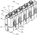
- Fig. 1 shows a view of a connection device 200.
- the connection device 200 is used for electrically connecting electrical conductors.
- the connection device 200 comprises a plurality of electrical connectors, which are arranged in the interior of the connection device 200 in a specially designed contact carrier 201 and 203.
- the contact carrier 201 comprises an upper housing part 201 and a lower housing part 203. Between the upper housing part 201 and the lower housing part 203, the electrical connectors are inserted and fixed. In the upper housing part 201 and the lower housing part 203 locking means for locking the upper housing part 201 are arranged with the lower housing part 203.
- the electrical connectors each comprise a jacket terminal and a plug contact pin 109.
- the jacket terminal allows the connection of several unfinished fine wire conductor in different cross sections without limiting the clarity in a mounting area.
- the upper housing part 201 comprises a plurality of jacket terminal openings 205, via which the electrical conductors are inserted laterally into the jacket terminals of the electrical connectors.
- the jacket clamp openings 205 are arranged on the side wall of the contact carrier.
- the connection device 200 comprises a feed channel between the jacket terminal opening 205 and the jacket clamp.
- At the top of the upper housing part 201 are a plurality of insertion openings 207, which serve for producing an electrical connection by means of the plug contact pin 109.
- a rotatable marking cap 209 is provided which is placed on a sheath clamp upper part.
- the marker cap 209 is replaceable by a user so that, depending on a color of the marker cap 209 used, a type of conductor can be identified.
- the marking cap 209 is formed from an electrically insulating material and serves to be placed on the jacket terminal shell 105 of the jacket clamp 103, 105.
- the marker cap 209 includes an edge with a knurled wheel profile 211 so that it can be easily turned by a user by hand.
- the marking cap 209 comprises a recess 213 for exposing a groove of the jacket terminal upper part of the jacket clamp.
- a Farbmarkiertiv 217 In a screw for the jacket clamp a Farbmarkiertiv 217 is used, which can be replaced depending on the desired color by a user.
- the color marker inserts 217 color coding and labeling of the connection areas is achieved.
- cylindrical elastomeric elements 219 are arranged, which hold the conductors in position.
- the elastomer elements 219 adapts to the different conductor diameters due to their special shape and internal structure. Through the wall of the upwardly outgoing pin contact of the double plug-in outlet a counterforce is generated.
- the Farbmarkieronia 217 is slidably disposed in the screw so that upon rotation of the marking cap 209 of the Farbmarkiernos 217 is moved simultaneously in the direction of an elastomer element 219.
- the Farbmarkiernos 217 thus also serves as a compression device for the elastomer element 219th
- the elastomeric element 219 is disposed laterally in the jacket clamp opening 205, so that an inserted conductor is located between an inner wall of the jacket clamp opening 205 and the elastomer element 219. If the elastomer element 219 is compressed from above by the color marker insert 217, this expands laterally and thereby fixes the inserted electrical conductor. A central recess 221 inside the elastomeric member 219 facilitates lateral expansion of the elastomeric member 219.
- Elastomers are understood to mean dimensionally stable but elastically deformable plastics whose glass transition temperature is below the use temperature.
- the elastomers can deform elastically under tension and compression, but then return to their original, undeformed shape.
- the elastomer may be made of a material containing natural rubber and / or silicone rubber.
- connection device 200 enables connection and reconnection of two or more cut, fine-wire electrical conductors of a main circuit without relevant contact resistance and with low heat loss.
- an open terminal area in which the conductor feed direction is perpendicular to the conductor instead of in the conductor direction.
- the arrangement of the plug contact pin 109 allows contacting with other mounting and installation levels.
- the connection device 200 comprises in each case five electrical connections with the respective connection possibilities.
- Fig. 2 shows a view of another connection device 200.
- the connection device 200 includes ten electrical connectors with the respective connection options.
- the electrical connectors are alternately oriented in the interior of the contact carrier 201 and 203 to each other.
- the elastomer element 219 is arranged between two jacket clamp openings 205, so that one or two left and right electrical conductors can be fixed simultaneously when compressing the elastomer element 219.
- the elastomer element 219 comprises a lateral retaining profile 223, which increases the adhesion to the electrical conductor used.
- the elastomeric element 219 is disposed between the color marker insert 217 and the contact carrier 201, 203.
- a first jacket clamp opening 205 is arranged on a side wall and a second jacket clamp opening 205 on an opposite side wall, so that they form a continuous feed channel for inserting an electrical conductor into the contact carrier 201.
- the contact carrier 201 comprises a jacket terminal opening 205 with a first elastomer element 219 on the side wall thereof and a second jacket terminal opening 205 with a second elastomer element 219 on the opposite side wall.
- supply channels for the insulated conductors run on both sides of the clamping point embedded in the contact carrier 201. Finely stranded and non-assembled cables of different cross sections can be inserted in the supply channels. A conductor inserted into the open terminal point and stripped is held in position in the supply channel, while further conductors can be inserted into the terminal point. The conductors can be inserted and held from both sides
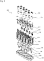
- Fig. 3 shows an exploded view of the connecting device 200.
- the connecting device 200 is made of the housing base 203, the electrical connectors used 100 with a jacket clamp base 103 and the plug contact pin 109, the upper housing part 201, the elastomeric elements 219, Color marker inserts 217, the sheath terminal shells 105 and the marker caps 209 assembled.
- the jacket clamp upper part 105 serves for the sleeve-shaped receiving of the jacket clamp lower part 103.
- the upper housing part 201 comprises the screw channels 215, in which the color marker inserts 217 are used together with the jacket clamp upper parts 105 and the color marker inserts 217.
- the contact carrier 201, 203 therefore comprises the screw channel 215 for inserting the rotatable jacket terminal upper part 105 of the jacket clamp 103, 105.
- the housing upper part 201 spikes 225 for placing the elastomeric elements 219.
- the elastomeric elements 219 also have a through recess 227, in which the mandrels 225 are used.
- the mandrels 225 and the recesses 227 are cross-shaped in cross section, so that a rotation of the elastomeric elements 219 is prevented.
- the elastomer elements 219 have a cylindrical basic shape.
- the housing lower part 203 comprises, for each electrical connector 100, a recess 229 into which a lower portion of the plug contact pins 109 is inserted.
- the electrical connector 100 is inserted with the plug contact pin 109 in the housing lower part (203).
- the electrical connectors 100 can be pre-stored in the housing base 203 and the mounting of the terminal device 200 is simplified when assembling the individual components.
- Fig. 4 shows a further view of the connecting device 200 with inserted electrical conductors 101.
- the electrical conductors 101 are inserted from both sides into the respective jacket terminal opening 205 and extend to the jacket terminal 103 and 105.
- the electrical conductors 101 run laterally on the elastomer elements 219 over.
- the electrical conductors 101 are clamped between the elastomeric members 219 and a side wall, not shown.
- Fig. 5 shows an enlarged view through the connecting device 200 with inserted electrical conductors 101.
- the stripped ends of the electrical conductor 101 lie in a U-shaped receptacle 107 of the Mantelklemmenunterteils 103 and are pressed by a pressure piece 131 in the jacket clamp upper part 105 on the Mantelklemmenunterteil 103, so that an electrical contact is created.
- the jacket clamp upper part 105 is rotated so that it moves downwards.
- the jacket clamp 103 and 105 is fastened by means of a nut 117.
- a groove 128 or the like for inserting a rotary tool, such as a screwdriver.
- Fig. 6 shows an enlarged cross-sectional view through the connecting device 200.
- the jacket clamp 103 and 105 is in the open position.
- the electrical conductors 101 are located in front of the respective elastomer elements 219.
- In the marking cap 209 is the recess 213 for exposing the underlying groove of the jacket clamp upper part 105th
- Fig. 7 shows a plan view of the connecting device 200.
- the marker cap 209 with the underlying jacket clamps 103 and 105 are alternately left and right on the top of the upper housing 203 arranged.
- the plug contact pins 109 are located next to the associated marking caps 209.
- the electrical conductors 101 are inserted from the left and right of the connection device 200 into the jacket clamp opening 205.
- Fig. 8 shows an enlarged plan view of the connecting device 200.
- the elastomeric element 219 presses laterally on the inserted electrical conductor 101 and fixes them by the holding profile 223 rests against the electrical conductor 101.
- the elastomer elements 219 thus exert a grip on the surface of the conductor insulation due to their special surface design.
- Fig. 9 shows a bottom view of the upper housing part 201 of the connecting device 200.
- the jacket clamps and the plug contact pins 109 are electrically connected to each other via a contact bridge 111 and with a mutual distance on the Contact bridge 111 attached.
- the contact bridges 111 are arranged diagonally in the interior of the contact carrier 201 and 203.
- Fig. 10 shows an exploded view of an electrical connector 100.
- the electrical connector 100 is composed of the plug contact pin 109, the plate-shaped contact bridge 111 and the sheath terminal with the sheath terminal lower part 103 and the sheath terminal shell 105.
- the plate-shaped contact bridge 111 is formed from a metal strip and comprises a jacket terminal opening 113 for inserting the jacket terminal 103, 105 and a pin opening 121 for insertion of the plug contact pin 109.
- the contact bridge 111 has a rectangular basic shape whose sides are semicircular.
- the plug contact pin 109 includes a tapered portion 127 and a stopper portion 129.
- the tapered portion 127 widened toward the stopper portion 129, so that it finds increasing support when inserted into the pin hole 121.
- the stopper portion 129 forms a stopper upon insertion of the plug contact pin 109, so that the plug contact pin 109 can be fixed in the intended position.
- the jacket clamp base 103 comprises a U-shaped receptacle 107 for inserting the electrical conductors.
- the jacket clamp lower part 103 comprises a threaded pin 115 with an externally threaded portion which is inserted into the jacket clamp opening 113 of the contact bridge 111. Subsequently, the jacket clamp base 103 is fastened to the contact bridge 111 with a nut 117 and a plate spring 119.
- the jacket terminal shell 105 is screwed onto the jacket terminal lower part 103 so that the inserted electrical conductors are clamped between the two parts.
- Fig. 11 shows a side exploded view of the electrical connector 100.
- the pressure piece 131 is rotatably mounted in the interior of the sleeve-shaped jacket terminal shell 105 and is used when placing the jacket terminal shell 105 on the jacket clamp base 103 in the U-shaped receptacle.
- the pressure piece 131 is pressed onto the electrical conductor lying in the receptacle 107, so that an electrical contact can be established between them.
- Fig. 12 shows a further side exploded view of the electrical connector 100.
- the plug contact pin 109 is inserted into the insertion opening 121 in the contact bridge 111. Between the plug contact pin 109 and the contact bridge 111 creates a conductive connection. The plug contact pin 109 projects vertically out of the contact bridge 111.
- Fig. 13 shows a side view of the electrical connector 100.
- the jacket clamp base 103 is screwed by means of the nut 117 on the contact bridge 111. This creates a conductive connection between the contact bridge 111 and the jacket terminal lower part 103.
- the plate spring 119 is inserted between the contact bridge 111 and the nut 117. By the plate spring 119, the screw is held under tension and prevents loosening of the nut 117.
- the plug contact pin 109 extends parallel to the jacket terminal 103, 105.
- Fig. 14 shows a view of the composite electrical connector 100.
- the jacket clamp upper part 105 is screwed onto the jacket clamp base 103. Between the two parts is the receptacle 107, are inserted into the electrical conductors.
- the jacket terminal 103 and 105 is oriented such that the direction of insertion of the conductor into the receptacle 107 is not obscured or obstructed by the plug contact pin 109.
- the stopper portion 129 When mounting the electrical connector 100 in the contact carrier 203, the stopper portion 129 is positively inserted into the recess 229 in the housing base 203.
- the stop portion 129 on the underside spring segments 133 which are pressed together when inserting and hold the plug contact pin 109 in the recess 229.
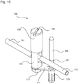
- Fig. 15 shows a view of the composite electrical connector 100 with inserted conductors 101.
- the electrical conductor 101 runs laterally past the contact pin 109.
- the electrical conductor 101 is for example a cable whose stripped ends are inserted in the receptacle 107. After screwing on the jacket terminal shell 105, electrical contact is made between the electrical conductors.
- Fig. 16 shows a perspective view of an arrangement of a plurality of electrical connectors 100, as they are arranged in the contact carrier 201 and 203 of the connection device 200.
- the arrangement shown, the electrical conductor can be spatially denser summarized by a combination of terminals with similar task.
- Fig. 17 shows a side view of an arrangement of a plurality of electrical connectors 100, as they are arranged in the contact carrier 201 and 203 of the connection device 200.
- the jacket clamps 105 and the plug contact pins 109 are aligned parallel to one another.
- Fig. 18 shows a plan view of an arrangement of a plurality of electrical connectors 100, as they are arranged in the contact carrier 201 and 203 of the connection device 200.
- the contact bridges 111 of the external electrical connectors 100 are angled.
- the electrical connectors 100 are arranged diagonally.
- Fig. 19 shows a view of an arrangement of a plurality of electrical connectors 100 with corresponding conductors 101, as they are arranged in the contact carrier 201 and 203 of the connection device 200.
- connection device 200 can be used as a space-saving cable installation technology for small and low voltage devices in the field. In addition, this one
- connection device 200 implements an integrated design concept which achieves an advantageous energy distribution in the field, i. outside a cabinet.
- connection device 200 with the contact carrier 201, 203 serves to guide and hold the individual conductors without limiting the clarity in the assembly area.
- a terminal space which is open from above and accessible from both sides is realized.
- a high level of error safety is achieved through clear routing and colored markings and a simple visual check after installation is possible.
- a positioning, guiding and holding the individual conductors of different cross sections in the contact carrier 201, 203 is possible.
- connection device 200 By connecting device 200 creates a high contact safety in the installed state with touch-safe measuring points at all potentials. A combination of a multiple terminal point for unassembled cables with a double plug-in technology is realized.
- the contact carrier 201, 203 is easily expandable to a five-pole star distributor for up to eight five-pin cables. Overall, this results in a space-saving cable installation technology for general connection and distribution boxes. In addition, there is mounting support in connection and distribution boxes with a large number of conductors and optimized cable routing.
Landscapes
- Connector Housings Or Holding Contact Members (AREA)
- Details Of Connecting Devices For Male And Female Coupling (AREA)
Claims (15)
- Connecteur électrique (100) pour la mise en contact électrique d'un conducteur électrique (101) avec une borne à chemise (103, 105) pour la mise en place du conducteur électrique (101), une fiche de contact (109) insérable dans une douille et un pont de contact (111) sur lequel sont fixées la borne à chemise (103, 105) et la fiche de contact (109), la borne à chemise (103, 105) comprenant une pièce inférieure (103) de borne à chemise et une pièce supérieure (105) de borne à chemise vissable sur celle-ci, et la pièce supérieure (105) de borne à chemise présentant une réception (125) pour un outil rotatif, en particulier une fente, une rainure, une tête hexagonale ou un trou hexagonal pour l'insertion d'un outil rotatif, caractérisé en ce que
la borne à chemise (103, 105) présente un évidement en U pour la mise en place du conducteur électrique (101), en ce que
le pont de contact (111) présente une ouverture (113) de borne à chemise pour la connexion électrique avec la borne à chemise (103, 105), et en ce que
le pont de contact (111) présente une ouverture pour fiche (121) pour l'insertion de la fiche de contact (109). - Connecteur électrique (100) selon la revendication 1, où la borne à chemise (103, 105) sur le pont de contact (111) est électriquement connectée, en particulier vissée, rivetée, emmanchée sous pression ou soudée.
- Connecteur électrique (100) selon l'une des revendications précédentes, où la borne à chemise (103, 105) comprend une broche filetée (115) pour la fixation de la borne à chemise (103, 105) contre le pont de contact (111) au moyen d'un écrou (117), et où une rondelle-ressort (119) est en particulier disposée entre l'écrou (117) et le pont de contact (111).
- Connecteur électrique (100) selon l'une des revendications précédentes, où l'ouverture pour fiche (121) présente des évidements radiaux (123).
- Connecteur électrique (100) selon l'une des revendications 1 à 4, où la pièce supérieure (105) de borne à chemise est réalisée en forme de manchon pour la réception de la pièce inférieure (103) de borne à chemise.
- Connecteur électrique (100) selon l'une des revendications 1 à 5, où la pièce supérieure (105) de borne à chemise comprend une pièce de pression (131) logée par rotation à l'intérieur, ou où la pièce supérieure (105) de borne à chemise contient une tige de pression fixe.
- Connecteur électrique (100) selon l'une des revendications précédentes, où la fiche de contact (109) s'étend parallèlement à la borne à chemise (103, 105).
- Dispositif de connexion (200) avec un connecteur électrique (100) selon l'une des revendications précédentes pour la connexion des conducteurs électriques (101), et un porte-contact (201, 203) pour la réception du connecteur électrique (100) présentant une ouverture (205) de borne à chemise pour la mise en place du conducteur électrique (101) dans la borne à chemise (103, 105) et une ouverture d'enfichage (207) pour l'engagement d'une douille sur la fiche de contact (109).
- Dispositif de connexion (200) selon la revendication 8, où l'ouverture (205) de borne à chemise est présentée sur une paroi latérale du porte-contact (201), où le porte-contact (201, 203) présente une première ouverture (205) de borne à chemise sur une paroi latérale et une deuxième ouverture (205) de borne à chemise sur une paroi latérale opposée.
- Dispositif de connexion (200) selon l'une des revendications précédentes 8 à 9, où l'ouverture d'enfichage (207) est disposée sur le dessus du porte-contact (201).
- Dispositif de connexion (200) selon l'une des revendications précédentes 8 à 10, où le porte-contact (201) comprend un capuchon isolant à marquage (209) destiné à être posé sur une pièce supérieure (105) de la borne à chemise (103, 105), le capuchon isolant à marquage (209) comprenant en particulier un profilé à molette (211).
- Dispositif de connexion (200) selon l'une des revendications précédentes 8 à 11, où le porte-contact (201, 203) comporte un canal de vissage (215) pour la mise en place de la pièce supérieure (105) rotative de la borne à chemise (103, 105), et où le porte-contact (201) comporte en particulier un insert à marquage de couleur (217) à mettre en place dans le canal de vissage (215).
- Dispositif de connexion (200) selon l'une des revendications précédentes 8 à 12, où le porte-contact (201, 203) comprend une pièce supérieure (201) de boîtier et une pièce inférieure (203) de boîtier,
le connecteur électrique (100) étant en particulier mis en place avec la fiche de contact (109) dans un évidement (229) de la pièce inférieure (203) de boîtier. - Dispositif de connexion (200) selon la revendication 13, où la pièce supérieure (201) de boîtier et la pièce inférieure (203) de boîtier sont assemblées.
- Dispositif de connexion (200) selon la revendication 13 ou 14, où le connecteur électrique (100) est fixé entre la pièce supérieure (201) de boîtier et la pièce inférieure (203) de boîtier.
Applications Claiming Priority (3)
| Application Number | Priority Date | Filing Date | Title |
|---|---|---|---|
| DE201310112083 DE102013112083A1 (de) | 2013-11-04 | 2013-11-04 | Elektrischer Verbinder mit einer Mantelklemme |
| DE201310112084 DE102013112084A1 (de) | 2013-11-04 | 2013-11-04 | Anschlussvorrichtung mit einem elektrischen Verbinder |
| PCT/EP2014/073596 WO2015063305A1 (fr) | 2013-11-04 | 2014-11-03 | Connecteur électrique muni d'une borne à capot taraudé |
Publications (2)
| Publication Number | Publication Date |
|---|---|
| EP3066720A1 EP3066720A1 (fr) | 2016-09-14 |
| EP3066720B1 true EP3066720B1 (fr) | 2019-01-30 |
Family
ID=51845424
Family Applications (1)
| Application Number | Title | Priority Date | Filing Date |
|---|---|---|---|
| EP14792836.0A Active EP3066720B1 (fr) | 2013-11-04 | 2014-11-03 | Connecteur électrique muni d'une borne à capot taraudé |
Country Status (4)
| Country | Link |
|---|---|
| US (1) | US9812793B2 (fr) |
| EP (1) | EP3066720B1 (fr) |
| CN (1) | CN105745791B (fr) |
| WO (1) | WO2015063305A1 (fr) |
Families Citing this family (2)
| Publication number | Priority date | Publication date | Assignee | Title |
|---|---|---|---|---|
| RU174855U1 (ru) * | 2017-03-14 | 2017-11-08 | Акционерное общество "Курский электроаппаратный завод" | Выключатель выдвижного исполнения |
| CN110112587A (zh) * | 2019-04-25 | 2019-08-09 | 四川安和精密电子电器有限公司 | 一种电路连接端子及其制造方法和牙刷马达 |
Family Cites Families (28)
| Publication number | Priority date | Publication date | Assignee | Title |
|---|---|---|---|---|
| DE872595C (de) | 1938-07-24 | 1953-04-02 | Gustav Hensel | Mit Anschlussklemmen und Sicherungen versehener wasserdichter Abzweigkasten |
| DE683862C (de) | 1939-01-08 | 1939-11-17 | Fritz Wieland | Mantelklemme fuer elektrische Leitungen |
| CH364825A (de) | 1959-01-30 | 1962-10-15 | Woertz Oskar | Erdleitungsverteiler für Schwachstrominstallationen |
| DE1801263U (de) | 1959-09-24 | 1959-12-03 | Harting Elektro W | Steckerstift und steckerbuchse. |
| DE1199353B (de) | 1962-04-05 | 1965-08-26 | Bogenschuetz G M B H Elektrote | Sockel fuer elektrische Installationsgeraete, insbesondere fuer elektrische Sicherungen |
| SE352484B (fr) | 1968-07-02 | 1972-12-27 | Installationsmateriel Ab | |
| FR2215713B3 (fr) | 1973-01-29 | 1976-01-30 | Forest Roland Fr | |
| FR2330293A7 (fr) | 1973-12-05 | 1977-05-27 | Perrichon Albert | Connecteur a autoserrage pour branchements electriques |
| US4375311A (en) | 1980-11-05 | 1983-03-01 | Amp Incorporated | Diode connector |
| US6111201A (en) | 1997-05-22 | 2000-08-29 | Thomas & Betts International, Inc. | Cable splice closure |
| DE29817007U1 (de) | 1998-09-22 | 1998-12-24 | Siemens Ag | Führungsstift für elektrische Steckverbindungen |
| JP3326413B2 (ja) * | 1999-09-10 | 2002-09-24 | エスエムケイ株式会社 | 端子コネクタ |
| DE29916602U1 (de) | 1999-09-22 | 2000-01-13 | Strack Holger | Elektrischer Steckverteilerblock |
| JP4443691B2 (ja) * | 1999-10-18 | 2010-03-31 | 第一電子工業株式会社 | 端子台 |
| DE10053302A1 (de) | 2000-04-26 | 2001-10-31 | Wieland Electric Gmbh | Mehrpoliger elektrischer Anschlußverbinder |
| CN2529404Y (zh) * | 2002-01-24 | 2003-01-01 | 李俊德 | 缆线中间连接器 |
| DE10339670B4 (de) | 2003-08-28 | 2006-02-16 | Siemens Ag | Klemmeinrichtung und damit ausgestattetes Schaltgerät zum Leiteranschluss mittels Ringkabelschuh |
| DE20315898U1 (de) * | 2003-10-16 | 2005-02-24 | Weidmüller Interface GmbH & Co. KG | Anschlußklemme zum Aufsetzen auf ein Trägerelement |
| CN2765341Y (zh) * | 2005-02-03 | 2006-03-15 | 李俊德 | 缆线中间连接器的接头嵌固构造 |
| CN2847568Y (zh) * | 2005-10-28 | 2006-12-13 | 惠州爱帝威电工科技有限公司 | 一种接线端子 |
| CN201084831Y (zh) * | 2007-07-11 | 2008-07-09 | 黄锦成 | 一种快速接头 |
| US7566250B1 (en) * | 2008-06-27 | 2009-07-28 | Tyco Electronics Corporation | Wire grounding assembly |
| US7559810B1 (en) * | 2008-11-05 | 2009-07-14 | Shang Tsai Wu | Terminal block structure |
| US7963811B2 (en) | 2009-02-12 | 2011-06-21 | Hubbell Incorporated | Electrical ground connector |
| US8105118B2 (en) * | 2009-10-22 | 2012-01-31 | Illinois Tool Works Inc. | Torque resistant terminal block element |
| DE202011103484U1 (de) | 2011-07-20 | 2012-10-25 | Bals Elektrotechnik Gmbh & Co. Kg | Kontaktelement für eine elektrische Steckverbindervorrichtung |
| WO2013019540A1 (fr) * | 2011-07-29 | 2013-02-07 | Washington Gas Light Company | Connecteur de mise à la masse |
| US8608518B2 (en) * | 2012-05-16 | 2013-12-17 | Dinkle Enterprise Co., Ltd. | Wire-grasping structure for terminal block |
-
2014
- 2014-11-03 CN CN201480060524.8A patent/CN105745791B/zh not_active Expired - Fee Related
- 2014-11-03 WO PCT/EP2014/073596 patent/WO2015063305A1/fr active Application Filing
- 2014-11-03 US US15/033,699 patent/US9812793B2/en active Active
- 2014-11-03 EP EP14792836.0A patent/EP3066720B1/fr active Active
Non-Patent Citations (1)
| Title |
|---|
| None * |
Also Published As
| Publication number | Publication date |
|---|---|
| WO2015063305A9 (fr) | 2016-04-21 |
| US9812793B2 (en) | 2017-11-07 |
| WO2015063305A1 (fr) | 2015-05-07 |
| CN105745791A (zh) | 2016-07-06 |
| CN105745791B (zh) | 2019-05-28 |
| US20160268705A1 (en) | 2016-09-15 |
| EP3066720A1 (fr) | 2016-09-14 |
Similar Documents
| Publication | Publication Date | Title |
|---|---|---|
| DE10001667C1 (de) | Mehrpoliger Überspannungsableiter zum Einsatz in Niederspannungs-Stromversorgungssystemen | |
| EP3282519B1 (fr) | Repartiteur modulaire pour des conduites electriques | |
| EP2351154B1 (fr) | Agencement de bornes en série avec raccordements transversaux et connecteurs d'essai | |
| EP1811604A2 (fr) | Barette à bornes électriques | |
| DE102015216541B4 (de) | Kontaktanordnung zur Kontaktierung einer berührungsgeschützten Stromschiene mittels einer Schienenkontaktierungshülse und Stecker mit einer solchen Kontaktanordnung | |
| EP2118969B1 (fr) | Système de connecteurs | |
| EP3066720B1 (fr) | Connecteur électrique muni d'une borne à capot taraudé | |
| DE102008019764A1 (de) | Kabelanschlußstecker | |
| DE10139202B4 (de) | Elektrischer Verteiler | |
| WO2015144910A1 (fr) | Dispositif de connexion électrique | |
| EP1388914A1 (fr) | Système de raccordement | |
| EP3066719B1 (fr) | Dispositif de raccordement servant à connecter des conducteurs électriques | |
| EP4099513A1 (fr) | Système de module de mesure | |
| DE102013112084A1 (de) | Anschlussvorrichtung mit einem elektrischen Verbinder | |
| DE102013112093A1 (de) | Anschlussvorrichtung mit einem elektrischen Verbinder | |
| EP3852201A1 (fr) | Système de connexion directe pour la connexion d'un connecteur à une carte de circuit imprimé | |
| DE102013112083A1 (de) | Elektrischer Verbinder mit einer Mantelklemme | |
| EP1039606B1 (fr) | Dispositif pour connecter électriquement au moins deux appareils electriques | |
| DE102012224259A1 (de) | Steckdoseneinsatz | |
| DE4411731A1 (de) | Aufputz-Steckdose | |
| DE10006143A1 (de) | Gerätesteckdose | |
| EP0633475B1 (fr) | Adaptateur pour appareils électriques | |
| DE102016121966A1 (de) | Kontakteinsatz für ein Steckverbinderteil | |
| DE102008019763A1 (de) | Befestigungsvorrichtung zur lösbaren rastenden Halterung eines elektrischen Verteilers | |
| DE102015110223A1 (de) | Baugruppe einer Klemmeneinrichtung zum Anschließen von elektrischen Leitern |
Legal Events
| Date | Code | Title | Description |
|---|---|---|---|
| PUAI | Public reference made under article 153(3) epc to a published international application that has entered the european phase |
Free format text: ORIGINAL CODE: 0009012 |
|
| 17P | Request for examination filed |
Effective date: 20160601 |
|
| AK | Designated contracting states |
Kind code of ref document: A1 Designated state(s): AL AT BE BG CH CY CZ DE DK EE ES FI FR GB GR HR HU IE IS IT LI LT LU LV MC MK MT NL NO PL PT RO RS SE SI SK SM TR |
|
| AX | Request for extension of the european patent |
Extension state: BA ME |
|
| RIN1 | Information on inventor provided before grant (corrected) |
Inventor name: SALOMON, THOMAS Inventor name: BURY, JOACHIM |
|
| DAX | Request for extension of the european patent (deleted) | ||
| STAA | Information on the status of an ep patent application or granted ep patent |
Free format text: STATUS: EXAMINATION IS IN PROGRESS |
|
| 17Q | First examination report despatched |
Effective date: 20180123 |
|
| GRAP | Despatch of communication of intention to grant a patent |
Free format text: ORIGINAL CODE: EPIDOSNIGR1 |
|
| STAA | Information on the status of an ep patent application or granted ep patent |
Free format text: STATUS: GRANT OF PATENT IS INTENDED |
|
| INTG | Intention to grant announced |
Effective date: 20180910 |
|
| GRAS | Grant fee paid |
Free format text: ORIGINAL CODE: EPIDOSNIGR3 |
|
| GRAA | (expected) grant |
Free format text: ORIGINAL CODE: 0009210 |
|
| STAA | Information on the status of an ep patent application or granted ep patent |
Free format text: STATUS: THE PATENT HAS BEEN GRANTED |
|
| AK | Designated contracting states |
Kind code of ref document: B1 Designated state(s): AL AT BE BG CH CY CZ DE DK EE ES FI FR GB GR HR HU IE IS IT LI LT LU LV MC MK MT NL NO PL PT RO RS SE SI SK SM TR |
|
| REG | Reference to a national code |
Ref country code: GB Ref legal event code: FG4D Free format text: NOT ENGLISH |
|
| REG | Reference to a national code |
Ref country code: CH Ref legal event code: EP |
|
| REG | Reference to a national code |
Ref country code: AT Ref legal event code: REF Ref document number: 1093991 Country of ref document: AT Kind code of ref document: T Effective date: 20190215 |
|
| REG | Reference to a national code |
Ref country code: IE Ref legal event code: FG4D Free format text: LANGUAGE OF EP DOCUMENT: GERMAN |
|
| REG | Reference to a national code |
Ref country code: DE Ref legal event code: R096 Ref document number: 502014010729 Country of ref document: DE |
|
| REG | Reference to a national code |
Ref country code: LT Ref legal event code: MG4D |
|
| REG | Reference to a national code |
Ref country code: NL Ref legal event code: MP Effective date: 20190130 |
|
| PG25 | Lapsed in a contracting state [announced via postgrant information from national office to epo] |
Ref country code: LT Free format text: LAPSE BECAUSE OF FAILURE TO SUBMIT A TRANSLATION OF THE DESCRIPTION OR TO PAY THE FEE WITHIN THE PRESCRIBED TIME-LIMIT Effective date: 20190130 Ref country code: PL Free format text: LAPSE BECAUSE OF FAILURE TO SUBMIT A TRANSLATION OF THE DESCRIPTION OR TO PAY THE FEE WITHIN THE PRESCRIBED TIME-LIMIT Effective date: 20190130 Ref country code: ES Free format text: LAPSE BECAUSE OF FAILURE TO SUBMIT A TRANSLATION OF THE DESCRIPTION OR TO PAY THE FEE WITHIN THE PRESCRIBED TIME-LIMIT Effective date: 20190130 Ref country code: NL Free format text: LAPSE BECAUSE OF FAILURE TO SUBMIT A TRANSLATION OF THE DESCRIPTION OR TO PAY THE FEE WITHIN THE PRESCRIBED TIME-LIMIT Effective date: 20190130 Ref country code: PT Free format text: LAPSE BECAUSE OF FAILURE TO SUBMIT A TRANSLATION OF THE DESCRIPTION OR TO PAY THE FEE WITHIN THE PRESCRIBED TIME-LIMIT Effective date: 20190530 Ref country code: NO Free format text: LAPSE BECAUSE OF FAILURE TO SUBMIT A TRANSLATION OF THE DESCRIPTION OR TO PAY THE FEE WITHIN THE PRESCRIBED TIME-LIMIT Effective date: 20190430 Ref country code: FI Free format text: LAPSE BECAUSE OF FAILURE TO SUBMIT A TRANSLATION OF THE DESCRIPTION OR TO PAY THE FEE WITHIN THE PRESCRIBED TIME-LIMIT Effective date: 20190130 Ref country code: SE Free format text: LAPSE BECAUSE OF FAILURE TO SUBMIT A TRANSLATION OF THE DESCRIPTION OR TO PAY THE FEE WITHIN THE PRESCRIBED TIME-LIMIT Effective date: 20190130 |
|
| PG25 | Lapsed in a contracting state [announced via postgrant information from national office to epo] |
Ref country code: BG Free format text: LAPSE BECAUSE OF FAILURE TO SUBMIT A TRANSLATION OF THE DESCRIPTION OR TO PAY THE FEE WITHIN THE PRESCRIBED TIME-LIMIT Effective date: 20190430 Ref country code: LV Free format text: LAPSE BECAUSE OF FAILURE TO SUBMIT A TRANSLATION OF THE DESCRIPTION OR TO PAY THE FEE WITHIN THE PRESCRIBED TIME-LIMIT Effective date: 20190130 Ref country code: IS Free format text: LAPSE BECAUSE OF FAILURE TO SUBMIT A TRANSLATION OF THE DESCRIPTION OR TO PAY THE FEE WITHIN THE PRESCRIBED TIME-LIMIT Effective date: 20190530 Ref country code: RS Free format text: LAPSE BECAUSE OF FAILURE TO SUBMIT A TRANSLATION OF THE DESCRIPTION OR TO PAY THE FEE WITHIN THE PRESCRIBED TIME-LIMIT Effective date: 20190130 Ref country code: HR Free format text: LAPSE BECAUSE OF FAILURE TO SUBMIT A TRANSLATION OF THE DESCRIPTION OR TO PAY THE FEE WITHIN THE PRESCRIBED TIME-LIMIT Effective date: 20190130 Ref country code: GR Free format text: LAPSE BECAUSE OF FAILURE TO SUBMIT A TRANSLATION OF THE DESCRIPTION OR TO PAY THE FEE WITHIN THE PRESCRIBED TIME-LIMIT Effective date: 20190501 |
|
| PG25 | Lapsed in a contracting state [announced via postgrant information from national office to epo] |
Ref country code: AL Free format text: LAPSE BECAUSE OF FAILURE TO SUBMIT A TRANSLATION OF THE DESCRIPTION OR TO PAY THE FEE WITHIN THE PRESCRIBED TIME-LIMIT Effective date: 20190130 Ref country code: CZ Free format text: LAPSE BECAUSE OF FAILURE TO SUBMIT A TRANSLATION OF THE DESCRIPTION OR TO PAY THE FEE WITHIN THE PRESCRIBED TIME-LIMIT Effective date: 20190130 Ref country code: SK Free format text: LAPSE BECAUSE OF FAILURE TO SUBMIT A TRANSLATION OF THE DESCRIPTION OR TO PAY THE FEE WITHIN THE PRESCRIBED TIME-LIMIT Effective date: 20190130 Ref country code: RO Free format text: LAPSE BECAUSE OF FAILURE TO SUBMIT A TRANSLATION OF THE DESCRIPTION OR TO PAY THE FEE WITHIN THE PRESCRIBED TIME-LIMIT Effective date: 20190130 Ref country code: DK Free format text: LAPSE BECAUSE OF FAILURE TO SUBMIT A TRANSLATION OF THE DESCRIPTION OR TO PAY THE FEE WITHIN THE PRESCRIBED TIME-LIMIT Effective date: 20190130 Ref country code: EE Free format text: LAPSE BECAUSE OF FAILURE TO SUBMIT A TRANSLATION OF THE DESCRIPTION OR TO PAY THE FEE WITHIN THE PRESCRIBED TIME-LIMIT Effective date: 20190130 |
|
| REG | Reference to a national code |
Ref country code: DE Ref legal event code: R097 Ref document number: 502014010729 Country of ref document: DE |
|
| PG25 | Lapsed in a contracting state [announced via postgrant information from national office to epo] |
Ref country code: SM Free format text: LAPSE BECAUSE OF FAILURE TO SUBMIT A TRANSLATION OF THE DESCRIPTION OR TO PAY THE FEE WITHIN THE PRESCRIBED TIME-LIMIT Effective date: 20190130 |
|
| PLBE | No opposition filed within time limit |
Free format text: ORIGINAL CODE: 0009261 |
|
| STAA | Information on the status of an ep patent application or granted ep patent |
Free format text: STATUS: NO OPPOSITION FILED WITHIN TIME LIMIT |
|
| 26N | No opposition filed |
Effective date: 20191031 |
|
| PG25 | Lapsed in a contracting state [announced via postgrant information from national office to epo] |
Ref country code: SI Free format text: LAPSE BECAUSE OF FAILURE TO SUBMIT A TRANSLATION OF THE DESCRIPTION OR TO PAY THE FEE WITHIN THE PRESCRIBED TIME-LIMIT Effective date: 20190130 |
|
| PG25 | Lapsed in a contracting state [announced via postgrant information from national office to epo] |
Ref country code: TR Free format text: LAPSE BECAUSE OF FAILURE TO SUBMIT A TRANSLATION OF THE DESCRIPTION OR TO PAY THE FEE WITHIN THE PRESCRIBED TIME-LIMIT Effective date: 20190130 |
|
| REG | Reference to a national code |
Ref country code: CH Ref legal event code: PL |
|
| PG25 | Lapsed in a contracting state [announced via postgrant information from national office to epo] |
Ref country code: LU Free format text: LAPSE BECAUSE OF NON-PAYMENT OF DUE FEES Effective date: 20191103 Ref country code: CH Free format text: LAPSE BECAUSE OF NON-PAYMENT OF DUE FEES Effective date: 20191130 Ref country code: MC Free format text: LAPSE BECAUSE OF FAILURE TO SUBMIT A TRANSLATION OF THE DESCRIPTION OR TO PAY THE FEE WITHIN THE PRESCRIBED TIME-LIMIT Effective date: 20190130 Ref country code: LI Free format text: LAPSE BECAUSE OF NON-PAYMENT OF DUE FEES Effective date: 20191130 |
|
| REG | Reference to a national code |
Ref country code: BE Ref legal event code: MM Effective date: 20191130 |
|
| GBPC | Gb: european patent ceased through non-payment of renewal fee |
Effective date: 20191103 |
|
| PG25 | Lapsed in a contracting state [announced via postgrant information from national office to epo] |
Ref country code: IE Free format text: LAPSE BECAUSE OF NON-PAYMENT OF DUE FEES Effective date: 20191103 Ref country code: GB Free format text: LAPSE BECAUSE OF NON-PAYMENT OF DUE FEES Effective date: 20191103 |
|
| PG25 | Lapsed in a contracting state [announced via postgrant information from national office to epo] |
Ref country code: BE Free format text: LAPSE BECAUSE OF NON-PAYMENT OF DUE FEES Effective date: 20191130 |
|
| REG | Reference to a national code |
Ref country code: AT Ref legal event code: MM01 Ref document number: 1093991 Country of ref document: AT Kind code of ref document: T Effective date: 20191103 |
|
| PG25 | Lapsed in a contracting state [announced via postgrant information from national office to epo] |
Ref country code: AT Free format text: LAPSE BECAUSE OF NON-PAYMENT OF DUE FEES Effective date: 20191103 |
|
| PGFP | Annual fee paid to national office [announced via postgrant information from national office to epo] |
Ref country code: IT Payment date: 20201120 Year of fee payment: 7 Ref country code: FR Payment date: 20201126 Year of fee payment: 7 |
|
| PG25 | Lapsed in a contracting state [announced via postgrant information from national office to epo] |
Ref country code: CY Free format text: LAPSE BECAUSE OF FAILURE TO SUBMIT A TRANSLATION OF THE DESCRIPTION OR TO PAY THE FEE WITHIN THE PRESCRIBED TIME-LIMIT Effective date: 20190130 |
|
| PG25 | Lapsed in a contracting state [announced via postgrant information from national office to epo] |
Ref country code: HU Free format text: LAPSE BECAUSE OF FAILURE TO SUBMIT A TRANSLATION OF THE DESCRIPTION OR TO PAY THE FEE WITHIN THE PRESCRIBED TIME-LIMIT; INVALID AB INITIO Effective date: 20141103 Ref country code: MT Free format text: LAPSE BECAUSE OF FAILURE TO SUBMIT A TRANSLATION OF THE DESCRIPTION OR TO PAY THE FEE WITHIN THE PRESCRIBED TIME-LIMIT Effective date: 20190130 |
|
| PG25 | Lapsed in a contracting state [announced via postgrant information from national office to epo] |
Ref country code: MK Free format text: LAPSE BECAUSE OF FAILURE TO SUBMIT A TRANSLATION OF THE DESCRIPTION OR TO PAY THE FEE WITHIN THE PRESCRIBED TIME-LIMIT Effective date: 20190130 |
|
| PG25 | Lapsed in a contracting state [announced via postgrant information from national office to epo] |
Ref country code: FR Free format text: LAPSE BECAUSE OF NON-PAYMENT OF DUE FEES Effective date: 20211130 |
|
| PG25 | Lapsed in a contracting state [announced via postgrant information from national office to epo] |
Ref country code: IT Free format text: LAPSE BECAUSE OF NON-PAYMENT OF DUE FEES Effective date: 20211103 |
|
| PGFP | Annual fee paid to national office [announced via postgrant information from national office to epo] |
Ref country code: DE Payment date: 20230127 Year of fee payment: 9 |
|
| P01 | Opt-out of the competence of the unified patent court (upc) registered |
Effective date: 20230424 |
|
| PGFP | Annual fee paid to national office [announced via postgrant information from national office to epo] |
Ref country code: DE Payment date: 20240129 Year of fee payment: 10 |