EP3066720B1 - Electrical connector with a sheath clamp - Google Patents
Electrical connector with a sheath clamp Download PDFInfo
- Publication number
- EP3066720B1 EP3066720B1 EP14792836.0A EP14792836A EP3066720B1 EP 3066720 B1 EP3066720 B1 EP 3066720B1 EP 14792836 A EP14792836 A EP 14792836A EP 3066720 B1 EP3066720 B1 EP 3066720B1
- Authority
- EP
- European Patent Office
- Prior art keywords
- sheath clamp
- electrical connector
- contact
- clamp
- connection device
- Prior art date
- Legal status (The legal status is an assumption and is not a legal conclusion. Google has not performed a legal analysis and makes no representation as to the accuracy of the status listed.)
- Active
Links
- 239000004020 conductor Substances 0.000 claims description 79
- 238000003780 insertion Methods 0.000 claims description 19
- 230000037431 insertion Effects 0.000 claims description 19
- 210000003813 thumb Anatomy 0.000 claims 1
- 238000003466 welding Methods 0.000 claims 1
- 229920001971 elastomer Polymers 0.000 description 19
- 239000000806 elastomer Substances 0.000 description 19
- 239000003550 marker Substances 0.000 description 16
- 238000005516 engineering process Methods 0.000 description 7
- 238000009434 installation Methods 0.000 description 7
- 230000006835 compression Effects 0.000 description 6
- 238000007906 compression Methods 0.000 description 6
- 239000002131 composite material Substances 0.000 description 4
- 238000010276 construction Methods 0.000 description 2
- 238000005315 distribution function Methods 0.000 description 2
- 238000002372 labelling Methods 0.000 description 2
- 244000043261 Hevea brasiliensis Species 0.000 description 1
- 230000001419 dependent effect Effects 0.000 description 1
- 230000000694 effects Effects 0.000 description 1
- 239000012777 electrically insulating material Substances 0.000 description 1
- 230000009477 glass transition Effects 0.000 description 1
- 238000002347 injection Methods 0.000 description 1
- 239000007924 injection Substances 0.000 description 1
- 238000009413 insulation Methods 0.000 description 1
- 239000000463 material Substances 0.000 description 1
- 239000002184 metal Substances 0.000 description 1
- 230000005405 multipole Effects 0.000 description 1
- 229920003052 natural elastomer Polymers 0.000 description 1
- 229920001194 natural rubber Polymers 0.000 description 1
- 239000004033 plastic Substances 0.000 description 1
- 229920003023 plastic Polymers 0.000 description 1
- 238000010079 rubber tapping Methods 0.000 description 1
- 229920002379 silicone rubber Polymers 0.000 description 1
- 239000004945 silicone rubber Substances 0.000 description 1
- 230000000007 visual effect Effects 0.000 description 1
Images


Classifications
-
- H—ELECTRICITY
- H01—ELECTRIC ELEMENTS
- H01R—ELECTRICALLY-CONDUCTIVE CONNECTIONS; STRUCTURAL ASSOCIATIONS OF A PLURALITY OF MUTUALLY-INSULATED ELECTRICAL CONNECTING ELEMENTS; COUPLING DEVICES; CURRENT COLLECTORS
- H01R4/00—Electrically-conductive connections between two or more conductive members in direct contact, i.e. touching one another; Means for effecting or maintaining such contact; Electrically-conductive connections having two or more spaced connecting locations for conductors and using contact members penetrating insulation
- H01R4/28—Clamped connections, spring connections
- H01R4/30—Clamped connections, spring connections utilising a screw or nut clamping member
- H01R4/32—Conductive members located in slot or hole in screw
-
- H—ELECTRICITY
- H01—ELECTRIC ELEMENTS
- H01R—ELECTRICALLY-CONDUCTIVE CONNECTIONS; STRUCTURAL ASSOCIATIONS OF A PLURALITY OF MUTUALLY-INSULATED ELECTRICAL CONNECTING ELEMENTS; COUPLING DEVICES; CURRENT COLLECTORS
- H01R13/00—Details of coupling devices of the kinds covered by groups H01R12/70 or H01R24/00 - H01R33/00
- H01R13/02—Contact members
- H01R13/04—Pins or blades for co-operation with sockets
Landscapes
- Connector Housings Or Holding Contact Members (AREA)
- Details Of Connecting Devices For Male And Female Coupling (AREA)
Description
Die Erfindung betrifft einen elektrischen Verbinder zum elektrischen Kontaktieren eines elektrischen Leiters mit einer Mantelklemme zum Einlegen des elektrischen Leiters.The invention relates to an electrical connector for electrically contacting an electrical conductor with a jacket clamp for inserting the electrical conductor.
Aus der Druckschrift
In der
In der Druckschrift
Es ist daher Aufgabe der vorliegenden Erfindung, einen elektrischen Verbinder zum elektrischen Kontaktieren von elektrischen Leitern bereitzustellen, der einen geringen Bauraum in Anspruch nimmt und weitere Anschlüsse zulässt.It is therefore an object of the present invention to provide an electrical connector for electrically contacting electrical conductors, which takes up a small installation space and allows further connections.
Diese Aufgabe wird durch die Gegenstände mit den Merkmalen nach den unabhängigen Ansprüchen gelöst. Vorteilhafte Ausführungsformen sind Gegenstand der abhängigen Ansprüche, der Beschreibung und der Zeichnungen.This object is solved by the objects with the features according to the independent claims. Advantageous embodiments are the subject of the dependent claims, the description and the drawings.
Gemäß einem ersten Aspekt wird die Aufgabe durch einen elektrischen Verbinder zum elektrischen Kontaktieren eines elektrischen Leiters mit einer Mantelklemme zum Einlegen des elektrischen Leiters, einem Steckkontaktstift zum Aufstecken einer Buchse und einer Kontaktbrücke gelöst, auf der die Mantelklemme und der Steckkontaktstift befestigt sind, wobei die Mantelklemme ein Mantelklemmenunterteil und ein aufschraubbares Mantelklemmenoberteil umfasst, wobei das Mantelklemmenoberteil eine Aufnahme für ein Drehwerkzeug, insbesondere einen Schlitz, eine Nut, einen Sechskantkopf oder ein Sechskantloch zum Einsetzen eines Drehwerkzeugs umfasst, wobei die Mantelklemme eine u-förmige Aussparung zum Einlegen des elektrischen Leiters umfasst, wobei die Kontaktbrücke eine Mantelklemmenöffnung zum elektrischen Verbinden mit der Mantelklemme umfasst, und wobei die Kontaktbrücke eine Stiftöffnung zum Einsetzen des Steckkontaktstifts umfasst. Durch die Kombination einer Mantelklemme mit einem Stift-Buchse-Kontakt mit einer Stromschiene als Kontaktbrücke wird beispielsweise der technische Vorteil erreicht, dass die Anschluss- und Verteilerfunktionen der Mantelklemme für die parallel eingeführten/durchgeführten flexiblen Leiter und die Steckfunktionen des Stift-Buchse-Kontakts versetzt sind und sich in unterschiedlichen Ebenen befinden, ohne sich gegenseitig bei der Montage zu stören. Der elektrische Verbinder kann beispielsweise in einer Funktionskomponente der Automatisierungstechnik, beispielsweise in einem Komponentenaufbausystem, insbesondere in einem Feldbussystem, eingesetzt werden.According to a first aspect, the object is achieved by an electrical connector for electrically contacting an electrical conductor with a jacket clamp for inserting the electrical conductor, a plug contact pin for attaching a socket and a contact bridge, on which the jacket clamp and the plug contact pin are attached, wherein the jacket clamp a jacket clamp base and a aufschraubbares Mantelklemmenoberteil, wherein the jacket clamp upper part comprises a receptacle for a rotary tool, in particular a slot, a groove, a hexagonal head or a hexagonal hole for insertion of a rotary tool, wherein the jacket clamp comprises a U-shaped recess for insertion of the electrical conductor, wherein the contact bridge a Clamp terminal opening for electrically connecting with the jacket clamp comprises, and wherein the contact bridge comprises a pin opening for insertion of the plug contact pin. By combining a jacket terminal with a pin-socket contact with a busbar as a contact bridge, for example, the technical advantage is achieved that the connection and distribution functions of the jacket terminal for the parallel imported / implemented flexible conductor and the plug functions of the pin-socket contact offset are and are on different levels without disturbing each other during assembly. The electrical connector can be used for example in a functional component of automation technology, for example in a component assembly system, in particular in a fieldbus system.
In einer vorteilhaften Ausführungsform des elektrischen Verbinders ist die Mantelklemme auf der Kontaktbrücke elektrisch verbunden, insbesondere aufgeschraubt, genietet, verpresst oder punktgeschweißt ist. Dadurch wird beispielsweise der technische Vorteil erreicht, dass auf einfache technische Weise eine feste Verbindung zwischen der Mantelklemme und der Kontaktbrücke hergestellt werden kann.In an advantageous embodiment of the electrical connector, the jacket clamp is electrically connected to the contact bridge, in particular screwed, riveted, pressed or spot-welded. As a result, for example, the technical advantage is achieved that in a simple technical way, a firm connection between the jacket clamp and the contact bridge can be made.
Der elektrische Verbinder umfasst eine Kontaktbrücke, die ihrerseits eine Mantelklemmenöffnung zum elektrischen Verbinden mit der Mantelklemme umfasst. Dadurch wird beispielsweise der technische Vorteil erreicht, dass die Mantelklemme in die Kontaktbrücke eingesetzt werden kann.The electrical connector includes a contact bridge, which in turn comprises a sheath terminal opening for electrical connection to the sheath terminal. As a result, the technical advantage is achieved, for example, that the jacket clamp can be used in the contact bridge.
In einer weiteren vorteilhaften Ausführungsform des elektrischen Verbinders umfasst die Mantelklemme einen Gewindestift zum Befestigen der Mantelklemme an der Kontaktbrücke mittels einer Mutter. Alternativ kann ein Befestigen mittels einer Niete, einer Verpressung oder einer Punktverschweißung erreicht werden. Dadurch wird beispielsweise der technische Vorteil erreicht, dass sich die eingesetzte Mantelklemme auf einfache Weise befestigen lässt.In a further advantageous embodiment of the electrical connector, the jacket clamp comprises a threaded pin for fastening the jacket clamp to the contact bridge by means of a nut. Alternatively, fastening can be accomplished by means of a rivet, a crimp or a spot weld. As a result, the technical advantage is achieved, for example, that can attach the inserted jacket clamp in a simple manner.
In einer weiteren vorteilhaften Ausführungsform des elektrischen Verbinders ist zwischen der Mutter und der Kontaktbrücke eine Tellerfeder angeordnet. Dadurch wird beispielsweise der technische Vorteil erreicht, dass ein unbeabsichtigtes Lösen der Mantelklemme verhindert wird.In a further advantageous embodiment of the electrical connector, a plate spring is arranged between the nut and the contact bridge. As a result, for example, the technical advantage is achieved that unintentional release of the jacket clamp is prevented.
Der elektrische Verbinder umfasst eine Kontaktbrücke, die ihrerseits eine Stiftöffnung zum Einsetzen des Steckkontaktstifts umfasst. Dadurch wird beispielsweise der technische Vorteil erreicht, dass der Steckkontaktstifts auf einfache Weise befestigt werden kann.The electrical connector comprises a contact bridge, which in turn comprises a pin opening for insertion of the plug contact pin. As a result, for example, the technical advantage is achieved that the plug contact pin can be easily attached.
In einer weiteren vorteilhaften Ausführungsform des elektrischen Verbinders umfasst die Stiftöffnung radiale Aussparungen. Dadurch wird beispielsweise der technische Vorteil erreicht, dass nachgebende Abschnitte um die Stiftöffnung herum erzeugt werden, die ein Einsetzen des Steckkontaktstifts erleichtern.In a further advantageous embodiment of the electrical connector, the pin opening comprises radial recesses. As a result, for example, the technical advantage achieved that yielding portions are generated around the pin opening, which facilitate insertion of the plug contact pin.
Die Mantelklemme umfasst ein Mantelklemmenunterteil und ein aufschraubbares Mantelklemmenoberteil. Dadurch wird beispielsweise der technische Vorteil erreicht, dass sich der elektrische Leiter auf einfache Weise befestigen lässt.The jacket terminal comprises a jacket terminal base and a screw-on jacket terminal shell. As a result, for example, the technical advantage is achieved that the electrical conductor can be easily attached.
Das Mantelklemmenunterteil umfasst eine u-förmige Aussparung zum Einlegen des elektrischen Leiters. Dadurch wird beispielsweise der technische Vorteil erreicht, dass der Leiter von dem Mantelklemmenunterteil umgeben wird und zuverlässig eingeklemmt werden kann. In einer weiteren vorteilhaften Ausführungsform des elektrischen Verbinders ist die u-förmige Aussparung oben abgeschrägt, um ein einfaches Einsetzen des Druckstückes zu ermöglichen.The jacket clamp base comprises a U-shaped recess for insertion of the electrical conductor. As a result, for example, the technical advantage is achieved that the conductor is surrounded by the jacket clamp base and can be clamped reliably. In a further advantageous embodiment of the electrical connector, the U-shaped recess is chamfered at the top to allow easy insertion of the pressure piece.
In einer weiteren vorteilhaften Ausführungsform des elektrischen Verbinders umfasst das Mantelklemmenoberteil eine Aufnahme für ein Drehwerkzeug, insbesondere einen Schlitz, eine Nut, einen Sechskantkopf oder ein Sechskantloch zum Einsetzen eines Drehwerkzeugs. Dadurch wird beispielsweise der technische Vorteil erreicht, dass ein hoher Anpressdruck auf die elektrischen Leiter erzeugt werden kann.In a further advantageous embodiment of the electrical connector, the jacket terminal upper part comprises a receptacle for a turning tool, in particular a slot, a groove, a hexagonal head or a hexagonal hole for inserting a turning tool. As a result, for example, the technical advantage is achieved that a high contact pressure can be generated on the electrical conductors.
In einer weiteren vorteilhaften Ausführungsform des elektrischen Verbinders ist das Mantelklemmenoberteil hülsenförmig zum Aufnehmen des Mantelklemmenunterteils ausgebildet. Dadurch wird beispielsweise der technische Vorteil erreicht, dass eine zuverlässige elektrische Verbindung zwischen den Leitern hergestellt werden kann.In a further advantageous embodiment of the electrical connector, the jacket terminal shell is sleeve-shaped for receiving the Mantelklemmenunterteils. As a result, for example, the technical advantage is achieved that a reliable electrical connection between the conductors can be made.
In einer weiteren vorteilhaften Ausführungsform des elektrischen Verbinders umfasst das Mantelklemmenoberteil ein drehbar im Inneren gelagertes Druckstück. Dadurch wird beispielsweise der technische Vorteil erreicht, dass das Druckstück in der u-förmigen Aussparung auf die elektrischen Leiter gedrückt werden kann.In a further advantageous embodiment of the electrical connector, the jacket terminal upper part comprises a rotatably mounted in the interior pressure piece. As a result, for example, the technical advantage is achieved that the pressure piece can be pressed in the U-shaped recess on the electrical conductors.
In einer weiteren vorteilhaften Ausführungsform des elektrischen Verbinders umfasst das Mantelklemmenoberteil einen festen Druckstift im Inneren. Dadurch wird beispielsweise der technische Vorteil erreicht, dass der Druckstift auf die elektrischen Leiter gedrückt werden kann.In a further advantageous embodiment of the electrical connector, the jacket terminal shell comprises a fixed pressure pin in the interior. As a result, for example, the technical advantage is achieved that the pressure pin can be pressed onto the electrical conductors.
In einer weiteren vorteilhaften Ausführungsform des elektrischen Verbinders umfasst der Steckkontaktstift einen konisch zulaufenden Abschnitt zum Einsetzen in die Stiftöffnung. Dadurch wird beispielsweise der technische Vorteil erreicht, dass ein Verklemmen bei der Montage des Steckkontaktstifts verhindert wird.In a further advantageous embodiment of the electrical connector of the plug contact pin comprises a tapered portion for insertion into the pin opening. As a result, for example, the technical advantage is achieved that jamming during assembly of the plug contact pin is prevented.
In einer weiteren vorteilhaften Ausführungsform des elektrischen Verbinders umfasst der Steckkontaktstift einen Anschlagsabschnitt zum Bilden eines Anschlags beim Einsetzen des Steckkontaktstifts in die Stiftöffnung. Dadurch wird beispielsweise der technische Vorteil erreicht, dass der Steckkontaktstift in der exakt vorgesehenen Position eingesetzt werden kann.In a further advantageous embodiment of the electrical connector of the plug contact pin comprises a stopper portion for forming a stopper upon insertion of the plug contact pin in the pin opening. As a result, for example, the technical advantage is achieved that the plug contact pin can be used in the exact intended position.
In einer weiteren vorteilhaften Ausführungsform des elektrischen Verbinders erstreckt sich der Steckkontaktstift parallel zu der Mantelklemme. Dadurch wird beispielsweise der technische Vorteil erreicht, dass seitlich elektrische Leiter zu der Mantelklemme zugeführt werden können und von oben eine Buchse zum Herstellen eines weiteren elektrischen Kontaktes auf den Steckkontaktstift aufgesetzt werden kann.In a further advantageous embodiment of the electrical connector, the plug contact pin extends parallel to the jacket clamp. As a result, for example, the technical advantage is achieved that laterally electrical conductors can be supplied to the jacket terminal and from above a socket for producing a further electrical contact can be placed on the plug contact pin.
Gemäß einem zweiten Aspekt wird die Aufgabe durch eine Anschlussvorrichtung mit einem elektrischen Verbinder zum Verbinden von elektrischen Leitern, der eine Mantelklemme und einen Steckkontaktstift, und einem Kontaktträger zum Aufnehmen des elektrischen Verbinders gelöst, der eine Mantelklemmenöffnung zum Einlegen der elektrischen Leiter in die Mantelklemme und eine Stecköffnung zum Aufstecken einer Buchse auf den Steckkontaktstift umfasst. Die Anschlussvorrichtung umfasst einen Zuführkanal zwischen der Mantelklemmenöffnung und der Mantelklemme. Dadurch wird beispielsweise der technische Vorteil erreicht, dass die Anschluss- und Verteilerfunktionen der Mantelklemme für die eingeführten/durchgeführten flexiblen Leiter kompakt angeordnet sind und eine größere Verdichtung des Verdrahtungsraums gegenüber einer Verwendung von Installationsboxen mit mehrpoligen Standardklemmen und Brücken erreicht wird.According to a second aspect, the object is achieved by a connection device having an electrical connector for connecting electrical conductors, a jacket clamp and a plug contact pin, and a contact carrier for receiving the electrical connector, a jacket terminal opening for inserting the electrical conductors into the jacket clamp and a Includes plug opening for attaching a socket on the plug contact pin. The connection device comprises a feed channel between the jacket terminal opening and the jacket clamp. As a result, for example, the technical advantage is achieved that the connection and distribution functions of the jacket clamp for the imported / implemented flexible conductors are arranged compact and a greater compression of the wiring space is achieved compared to a use of installation boxes with multipolar standard terminals and bridges.
Die Anschlussvorrichtung kann beispielsweise in einer Funktionskomponente der Automatisierungstechnik, beispielsweise in einem Komponentenaufbausystem, insbesondere in einem Feldbussystem, eingesetzt werden.The connection device can be used, for example, in a functional component of automation technology, for example in a component construction system, in particular in a fieldbus system.
In einer vorteilhaften Ausführungsform der Anschlussvorrichtung ist die Mantelklemmenöffnung an einer Seitenwand des Kontaktträgers angeordnet. Dadurch wird beispielsweise der technische Vorteil erreicht, dass die elektrische Leitung auf einfache Weise zugeführt werden kann, wenn die Anschlussvorrichtung an einer Wand montiert ist.In an advantageous embodiment of the connection device, the jacket clamp opening is arranged on a side wall of the contact carrier. As a result, for example, the technical advantage is achieved that the electrical line can be supplied in a simple manner when the connection device is mounted on a wall.
In einer weiteren vorteilhaften Ausführungsform der Anschlussvorrichtung umfasst der Kontaktträger eine erste Mantelklemmenöffnung an einer Seitenwand und eine zweite Mantelklemmenöffnung an einer gegenüberliegenden Seitenwand. Dadurch wird beispielsweise der technische Vorteil erreicht, dass ein durchgehender Zuführkanal zum Verbinden von elektrischen Leitern erzeugt wird.In a further advantageous embodiment of the connection device, the contact carrier comprises a first jacket clamp opening on a side wall and a second jacket clamp opening on an opposite side wall. As a result, for example, the technical advantage is achieved that a continuous feed channel for connecting electrical conductors is generated.
In einer weiteren vorteilhaften Ausführungsform der Anschlussvorrichtung ist die Stecköffnung an einer Oberseite des Kontaktträgers angeordnet. Dadurch wird beispielsweise der technische Vorteil erreicht, dass eine Abzweigung in Stecktechnik senkrecht zur Verdrahtungsebene ermöglicht wird.In a further advantageous embodiment of the connection device, the insertion opening is arranged on an upper side of the contact carrier. As a result, for example, the technical advantage is achieved that a diversion in plug-in technology is made possible perpendicular to the wiring level.
In einer weiteren vorteilhaften Ausführungsform der Anschlussvorrichtung umfasst der Kontaktträger eine isolierende Markierungskappe zum Aufsetzen auf ein Mantelklemmenoberteil der Mantelklemme. Dadurch wird beispielsweise der technische Vorteil erreicht, dass farblich unterschiedliche Markierungskappen zur Kennzeichnung einzelner Anschlüsse verwendet werden können und die Berührsicherheit erhöht wird.In a further advantageous embodiment of the connection device, the contact carrier comprises an insulating marking cap for placing on a jacket terminal upper part of the jacket clamp. As a result, for example, the technical advantage is achieved that color different marker caps can be used to identify individual ports and the touch safety is increased.
In einer weiteren vorteilhaften Ausführungsform der Anschlussvorrichtung umfasst die isolierende Markierungskappe ein Rändelradprofil. Dadurch wird beispielsweise der technische Vorteil erreicht, dass das Mantelklemmenoberteil von Hand betätigt werden kann.In a further advantageous embodiment of the connecting device, the insulating marking cap comprises a knurling wheel profile. As a result, the technical advantage is achieved, for example, that the jacket terminal shell can be operated by hand.
In einer weiteren vorteilhaften Ausführungsform der Anschlussvorrichtung umfasst die isolierende Markierungskappe eine Aussparung zum Freilegen einer Nut des Mantelklemmenoberteils der Mantelklemme. Dadurch wird beispielsweise der technische Vorteil erreicht, dass sowohl ein Drehwerkzeug als auch eine Messspitze zum Abgreifen einer Spannung in das Mantelklemmenoberteil eingesetzt werden kann.In a further advantageous embodiment of the connecting device, the insulating marking cap comprises a recess for exposing a groove of the jacket terminal upper part of the jacket clamp. As a result, for example, the technical advantage is achieved that both a turning tool and a measuring tip for tapping a voltage can be used in the jacket terminal shell.
In einer weiteren vorteilhaften Ausführungsform der Anschlussvorrichtung umfasst der Kontaktträger einen Schraubkanal zum Einsetzen des drehbaren Mantelklemmenoberteils der Mantelklemme. Dadurch wird beispielsweise der technische Vorteil erreicht, dass das Mantelklemmenoberteil berührsicher in der Anschlussvorrichtung geführt wird.In a further advantageous embodiment of the connection device, the contact carrier comprises a screw channel for insertion of the rotatable jacket terminal upper part of the jacket clamp. As a result, for example, the technical advantage is achieved that the jacket terminal shell is guided safe to touch in the connection device.
In einer weiteren vorteilhaften Ausführungsform der Anschlussvorrichtung umfasst der Kontaktträger einen Farbmarkiereinsatz zum Einsetzen in den Schraubkanal. Dadurch wird beispielsweise der technische Vorteil erreicht, dass eine benutzerspezifische Farbkennzeichnung und Beschriftung der Anschlussbereiche erreicht wird.In a further advantageous embodiment of the connection device, the contact carrier comprises a color marker insert for insertion into the screw. As a result, for example, the technical advantage is achieved that a user-specific color coding and labeling of the connection areas is achieved.
In einer weiteren vorteilhaften Ausführungsform der Anschlussvorrichtung umfasst der Kontaktträger ein Gehäuseoberteil und ein Gehäuseunterteil. Dadurch wird beispielsweise der technische Vorteil erreicht, dass ein modularer Aufbau der Anschlussvorrichtung erreicht wird und das Gehäuseoberteil und Gehäuseunterteil als Spritzgussformteile ausgebildet sein können.In a further advantageous embodiment of the connection device, the contact carrier comprises an upper housing part and a lower housing part. As a result, for example, the technical advantage is achieved that a modular construction of the connecting device is achieved and the upper housing part and lower housing part can be designed as injection molded parts.
In einer weiteren vorteilhaften Ausführungsform der Anschlussvorrichtung ist der elektrische Verbinder mit dem Steckkontaktstift in eine Aussparung in dem Gehäuseunterteil eingesetzt. Dadurch wird beispielsweise der technische Vorteil erreicht, dass der elektrische Verbinder beim Zusammensetzen der Anschlussvorrichtung vorgehaltert werden kann.In a further advantageous embodiment of the connection device, the electrical connector with the plug contact pin is inserted into a recess in the housing lower part. As a result, the technical advantage is achieved, for example, that the electrical connector can be pre-stored during assembly of the connection device.
In einer weiteren vorteilhaften Ausführungsform der Anschlussvorrichtung sind das Gehäuseoberteil und das Gehäuseunterteil miteinander verrastet. Dadurch wird beispielsweise der technische Vorteil erreicht, dass die Anschlussvorrichtung auf einfache Weise hergestellt werden kann.In a further advantageous embodiment of the connecting device, the upper housing part and the lower housing part are locked together. As a result, the technical advantage is achieved, for example, that the connection device can be produced in a simple manner.
In einer weiteren vorteilhaften Ausführungsform der Anschlussvorrichtung ist der elektrische Verbinder zwischen dem Gehäuseoberteil und dem Gehäuseunterteil fixiert. Dadurch wird beispielsweise ebenfalls der technische Vorteil erreicht, dass die Anschlussvorrichtung auf einfache Weise hergestellt werden kann.In a further advantageous embodiment of the connection device, the electrical connector is fixed between the upper housing part and the lower housing part. As a result, the technical advantage is achieved, for example, that the connection device can be made in a simple manner.
In einer weiteren vorteilhaften Ausführungsform der Anschlussvorrichtung umfasst der Kontaktträger ein Elastomerelement zum Fixieren des elektrischen Leiters in der Mantelklemmenöffnung. Dadurch wird beispielsweise der technische Vorteil erreicht, dass der elektrische Leiter in einem Zuführkanal eingeklemmt werden kann.In a further advantageous embodiment of the connection device, the contact carrier comprises an elastomer element for fixing the electrical conductor in the jacket clamp opening. As a result, for example, the technical advantage is achieved that the electrical conductor can be clamped in a feed channel.
In einer weiteren vorteilhaften Ausführungsform der Anschlussvorrichtung weist der Kontaktträger eine Mehrzahl von Aufnahmen für je einen elektrischen Verbinder auf. Dadurch wird beispielsweise der technische Vorteil erreicht, dass eine mehrere elektrische Leitungen mit einer einzigen Anschlussvorrichtung verbunden werden können.In a further advantageous embodiment of the connection device, the contact carrier has a plurality of receptacles for each electrical connector. As a result, for example, the technical advantage is achieved that a plurality of electrical lines can be connected to a single connection device.
Weitere Ausführungsbeispiele werden Bezug nehmend auf die beiliegenden Zeichnungen erläutert. Es zeigen:
- Fig. 1
- eine Ansicht einer Anschlussvorrichtung;
- Fig. 2
- eine Ansicht einer weiteren Anschlussvorrichtung;
- Fig. 3
- eine Explosionsansicht der Anschlussvorrichtung;
- Fig. 4
- eine weitere Ansicht der Anschlussvorrichtung mit eingesetzten elektrischen Leitern;
- Fig. 5
- eine vergrößerte Ansicht durch die Anschlussvorrichtung;
- Fig. 6
- eine vergrößerte Querschnittsansicht durch die Anschlussvorrichtung;
- Fig. 7
- eine Aufsicht auf die Anschlussvorrichtung;
- Fig. 8
- eine vergrößerte Aufsicht auf die Anschlussvorrichtung;
- Fig. 9
- eine Untersicht auf die Anschlussvorrichtung;
- Fig. 10
- eine Explosionsdarstellung eines elektrischen Verbinders;
- Fig. 11
- eine seitliche Explosionsdarstellung des elektrischen Verbinders;
- Fig. 12
- eine weitere seitliche Explosionsdarstellung des elektrischen Verbinders;
- Fig. 13
- eine Seitenansicht des elektrischen Verbinders;
- Fig. 14
- eine Ansicht des zusammengesetzten elektrischen Verbinders;
- Fig. 15
- eine Ansicht des zusammengesetzten elektrischen Verbinders mit eingesetzten Leitern;
- Fig. 16
- eine Ansicht einer Anordnung aus mehreren elektrischen Verbindern;
- Fig. 17
- eine Seitenansicht einer Anordnung aus mehreren elektrischen Verbindern;
- Fig. 18
- eine Aufsicht einer Anordnung aus mehreren elektrischen Verbindern; und
- Fig. 19
- eine Ansicht einer Anordnung aus mehreren elektrischen Verbindern mit entsprechenden Leitern.
- Fig. 1
- a view of a connection device;
- Fig. 2
- a view of another connection device;
- Fig. 3
- an exploded view of the connection device;
- Fig. 4
- a further view of the connection device with inserted electrical conductors;
- Fig. 5
- an enlarged view through the connecting device;
- Fig. 6
- an enlarged cross-sectional view through the connecting device;
- Fig. 7
- a plan view of the connection device;
- Fig. 8
- an enlarged view of the connection device;
- Fig. 9
- a bottom view of the connection device;
- Fig. 10
- an exploded view of an electrical connector;
- Fig. 11
- a side exploded view of the electrical connector;
- Fig. 12
- a further side exploded view of the electrical connector;
- Fig. 13
- a side view of the electrical connector;
- Fig. 14
- a view of the composite electrical connector;
- Fig. 15
- a view of the composite electrical connector with inserted conductors;
- Fig. 16
- a view of an arrangement of a plurality of electrical connectors;
- Fig. 17
- a side view of an arrangement of a plurality of electrical connectors;
- Fig. 18
- a plan view of an arrangement of a plurality of electrical connectors; and
- Fig. 19
- a view of an arrangement of a plurality of electrical connectors with corresponding conductors.
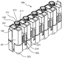
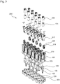
Der Kontaktträger 201 umfasst ein Gehäuseoberteil 201 und ein Gehäuseunterteil 203. Zwischen dem Gehäuseoberteil 201 und dem Gehäuseunterteil 203 sind die elektrischen Verbinder eingelegt und fixiert. In dem Gehäuseoberteil 201 und dem Gehäuseunterteil 203 sind Rastmittel zum Verrasten des Gehäuseoberteils 201 mit dem Gehäuseunterteil 203 angeordnet.The
Die elektrischen Verbinder umfassen jeweils eine Mantelklemme und einen Steckkontaktstift 109. Die Mantelklemme ermöglicht den Anschluss mehrerer unkonfektionierter feindrahtiger Leiter in unterschiedlichen Querschnitten ohne Einschränkung der Übersichtlichkeit in einem Montagebereich.The electrical connectors each comprise a jacket terminal and a
Das Gehäuseoberteil 201 umfasst mehrere Mantelklemmenöffnungen 205, über die die elektrischen Leiter seitlich in die Mantelklemmen der elektrischen Verbinder eingeführt werden. Die Mantelklemmenöffnungen 205 sind der Seitenwand des Kontaktträgers angeordnet. Die Anschlussvorrichtung 200 umfasst einen Zuführkanal zwischen der Mantelklemmenöffnung 205 und der Mantelklemme. An der Oberseite des Gehäuseoberteils 201 befinden sich mehrere Stecköffnungen 207, die zum Herstellen einer elektrischen Verbindung mittels des Steckkontaktstifts 109 dienen.The
Um die im Inneren des Kontaktträgers 201 und 203 gelegene Mantelklemme zu öffnen und zu schließen, ist eine drehbare Markierungskappe 209 vorgesehen, die auf ein Mantelklemmenoberteil gesetzt ist. Die Markierungskappe 209 ist durch einen Benutzer ersetzbar, so dass je nach einer verwendeten Farbe der Markierungskappe 209 ein Leitertyp gekennzeichnet werden kann. Die Markierungskappe 209 ist aus einem elektrisch isolierenden Material gebildet und dient zum Aufsetzen auf das Mantelklemmenoberteil 105 der Mantelklemme 103, 105.In order to open and close the sheath clamp located in the interior of the
Die Markierungskappe 209 umfasst einen Rand mit einem Rändelradprofil 211, so dass diese griffig durch einen Benutzer von Hand gedreht werden kann. Daneben umfasst die Markierungskappe 209 eine Aussparung 213 zum Freilegen einer Nut des Mantelklemmenoberteils der Mantelklemme.The
In einem Schraubkanal für die Mantelklemme ist ein Farbmarkiereinsatz 217 eingesetzt, der je nach gewünschter Farbe durch einen Benutzer ersetzt werden kann. Durch die Farbmarkiereinsätze 217 wird eine Farbkennzeichnung und Beschriftung der Anschlussbereiche erreicht.In a screw for the jacket clamp a
An der Eintrittsstelle der elektrischen Leiter in den Kontaktträger 201 sind zylinderförmige Elastomerelemente 219 angeordnet, welche die Leiter in Position halten. Die Elastomerelemente 219 passen sich durch ihre besondere Formgebung und ihren inneren Aufbau an die unterschiedlichen Leiterdurchmesser an. Durch die Wandung des nach oben abgehenden Stiftkontakts des Doppelsteckabgangs wird eine Gegenkraft erzeugt.At the point of entry of the electrical conductors in the
Der Farbmarkiereinsatz 217 ist in dem Schraubkanal verschiebbar angeordnet, so dass beim Zudrehen der Markierungskappe 209 der Farbmarkiereinsatz 217 zugleich in Richtung eines Elastomerelement 219 bewegt wird. Der Farbmarkiereinsatz 217 dient somit zudem als Kompressionseinrichtung für das Elastomerelement 219.The
Das Elastomerelement 219 ist seitlich in der Mantelklemmenöffnung 205 angeordnet, so dass sich ein eingesetzter Leiter zwischen einer Innenwand der Mantelklemmenöffnung 205 und dem Elastomerelement 219 befindet. Wird das Elastomerelement 219 von Oben durch den Farbmarkiereinsatz 217 komprimiert, dehnt sich dieses seitlich aus und fixiert dadurch den eingesetzten elektrischen Leiter. Eine zentrale Aussparung 221 im Inneren des Elastomerelements 219 erleichtert die seitliche Ausdehnung des Elastomerelements 219.The
Unter Elastomeren werden formfeste, aber elastisch verformbare Kunststoffe verstanden, deren Glasübergangstemperatur sich unterhalb der Einsatztemperatur befindet. Die Elastomere können sich bei Zug und Druck elastisch verformen, finden danach aber wieder in ihre ursprüngliche, unverformte Form zurück. Das Elastomer kann aus einem Material gefertigt sein, das Naturkautschuk und/oder Silikonkautschuk enthält.Elastomers are understood to mean dimensionally stable but elastically deformable plastics whose glass transition temperature is below the use temperature. The elastomers can deform elastically under tension and compression, but then return to their original, undeformed shape. The elastomer may be made of a material containing natural rubber and / or silicone rubber.
Durch die Anschlussvorrichtung 200 werden ein Anschluss und eine Wiederverbindung von zwei oder mehr geschnittenen, feindrahtigen elektrischen Leitern eines Hauptstromkreises ohne relevanten Übergangswiderstand und mit geringer Verlustwärme ermöglicht. Zudem entsteht durch den Steckkontaktstift 109 ein offener Klemmbereich, in dem die Leiterzuführungsrichtung senkrecht zum Leiter statt in Leiterrichtung verläuft. Die Anordnung des Steckkontaktstifts 109 ermöglicht eine Kontaktierung zu weiteren Montage- und Installationsebenen. Die Anschlussvorrichtung 200 umfasst jeweils fünf elektrische Anschlüsse mit den jeweiligen Anschlussmöglichkeiten. Durch die Anschlussvorrichtung 200 wird eine Verdichtung des Verdrahtungsraums gegenüber einer Verwendung von Installationsboxen mit mehrpoligen Standardklemmen und Brücken erreicht und eine Abzweigung vom mehrpoligen Leiterklemmbereich in Stecktechnik senkrecht zur Verdrahtungsebene ermöglicht.The
Eine erste Mantelklemmenöffnung 205 ist an einer Seitenwand und eine zweite Mantelklemmenöffnung 205 an einer gegenüberliegenden Seitenwand angeordnet, so dass diese einen durchgehenden Zuführkanal zum Einlegen eines elektrischen Leiters in den Kontaktträger 201 bilden. Der Kontaktträger 201 umfasst eine Mantelklemmenöffnung 205 mit einem ersten Elastomerelement 219 an dessen Seitenwand und eine zweite Mantelklemmenöffnung 205 mit einem zweiten Elastomerelement 219 an der gegenüberliegenden Seitenwand.A first jacket clamp opening 205 is arranged on a side wall and a second jacket clamp opening 205 on an opposite side wall, so that they form a continuous feed channel for inserting an electrical conductor into the
Auf die im Kontaktträger 201 eingebettete Klemmstelle laufen daher beidseitig Zuführkanäle für die isolierten Leiter zu. In die Zuführkanäle können feindrähtige und unkonfektionierte Leitungen unterschiedlicher Querschnitte eingelegt werden. Ein in die offene Klemmstelle eingelegter und abisolierter Leiter wird in dem Zuführkanal in Position gehalten, während weitere Leiter in die Klemmstelle eingelegt werden können. Die Leiter können von beiden Seiten eingelegt und gehalten werdenTherefore, supply channels for the insulated conductors run on both sides of the clamping point embedded in the
Das Gehäuseoberteil 201 umfasst die Schraubkanäle 215, in die die Farbmarkiereinsätze 217 zusammen mit den Mantelklemmenoberteilen 105 und den Farbmarkiereinsätzen 217 eingesetzt werden. Der Kontaktträger 201, 203 umfasst daher den Schraubkanal 215 zum Einsetzen des drehbaren Mantelklemmenoberteils 105 der Mantelklemme 103, 105.The
Zudem umfasst das Gehäuseoberteil 201 Dorne 225 zum Aufsetzen der Elastomerelemente 219. Zu diesem Zweck weisen die Elastomerelemente 219 ebenfalls eine durchgehende Aussparung 227 auf, in die die Dorne 225 eingesetzt werden. Die Dorne 225 und die Aussparungen 227 sind im Querschnitt kreuzförmig, so dass ein Verdrehen der Elastomerelemente 219 verhindert wird. Die Elastomerelemente 219 weisen eine zylindrische Grundform auf. Nach dem Zusammensetzen der Anschlussvorrichtung ragen die Dorne 225 in die Farbmarkiereinsätze 217 hinein. Hierzu weisen die Farbmarkiereinsätze 217 eine entsprechende Aussparung auf. Dadurch kann ein Abknicken der Dorne 225 verhindert werden.In addition, the housing
Das Gehäuseunterteil 203 umfasst zu jedem elektrischen Verbinder 100 eine Aussparung 229, in die ein unterer Abschnitt der Steckkontaktstifte 109 eingesetzt wird. Der elektrische Verbinder 100 ist mit dem Steckkontaktstift 109 in das Gehäuseunterteil (203) eingesetzt. Dadurch können die elektrischen Verbinder 100 in dem Gehäuseunterteil 203 vorgehaltert werden und die Montage der Anschlussvorrichtung 200 vereinfacht sich beim Zusammensetzen der Einzelkomponenten.The housing
An der Oberseite der Mantelklemmenöffnung 205 befindet sich eine Nut 128 oder Ähnliches zum Einsetzen eines Drehwerkzeuges, wie beispielsweise einem Schraubendreher.At the top of the jacket clamp opening 205 is a groove 128 or the like for inserting a rotary tool, such as a screwdriver.
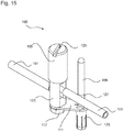
Der Steckkontaktstift 109 umfasst einen konisch zulaufenden Abschnitt 127 und einen Anschlagsabschnitt 129. Der konisch zulaufende Abschnitt 127 verbreitert sich zum Anschlagsabschnitt 129 hin, so dass dieser beim Einsetzen in die Stiftöffnung 121 zunehmend Halt findet. Der Anschlagsabschnitt 129 bildet einen Anschlag beim Einsetzen des Steckkontaktstifts 109, so dass der Steckkontaktstift 109 in der vorgesehen Position befestigt werden kann.The
Radial um die Stiftöffnung 121 sind Aussparungen 123 angeordnet, durch die um die Stiftöffnung 121 herum federnde Abschnitte in der Kontaktbrücke 111 erzeugt werden, die beim Einsetzen des konisch zulaufenden Abschnitts 127 leicht nachgeben und den Steckkontaktstift 109 an der Kontaktbrücke 111 fixieren.Radially around the pin opening 121
Das Mantelklemmenunterteil 103 umfasst eine u-förmige Aufnahme 107 zum Einlegen der elektrischen Leiter. Zudem umfasst das Mantelklemmenunterteil 103 einen Gewindestift 115 mit einem Außengewindeabschnitt, der in die Mantelklemmenöffnung 113 der Kontaktbrücke 111 eingesetzt wird. Anschließend wird das Mantelklemmenunterteil 103 mit einer Mutter 117 und einer Tellerfeder 119 an der Kontaktbrücke 111 befestigt.The
Das Mantelklemmenoberteil 105 wird auf das Mantelklemmenunterteil 103 aufgeschraubt, so dass die eingelegten elektrischen Leiter, zwischen beiden Teilen eingeklemmt werden. Zum Festdrehen des Mantelklemmenoberteils 105 auf dem Mantelklemmenunterteil 103 ist an der Oberseite die Nut 125 vorgesehen, in die ein Schraubendreher eingesetzt werden kann.The
Bei der Montage des elektrischen Verbinder 100 in dem Kontaktträger 203 wird der Anschlagsabschnitt 129 formschlüssig in die Aussparung 229 in dem Gehäuseunterteil 203 eingesetzt. Zu diesem Zweck weist der Anschlagsabschnitt 129 an der Unterseite Federsegmente 133 auf, die beim Einsetzen zusammengedrückt werden und den Steckkontaktstift 109 in der Aussparung 229 halten.When mounting the
Die Anschlussvorrichtung 200 kann als platzsparende Kabel-Installationstechnik für Klein- und Niederspannungsgeräte im Feld verwendet werden. Zudem stellt diese einenThe
Steckanschluss und eine Potential-Übergabe für modulare und stapelbare Gehäuse bereit. Durch die Anschlussvorrichtung 200 wird ein ganzheitliches Aufbaukonzept realisiert, durch das eine vorteilhafte Energieverteilung im Feld erreicht wird, d.h. außerhalb eines Schaltschranks.Plug-in connection and a potential transfer for modular and stackable housing ready. The
Die Anschlussvorrichtung 200 mit dem Kontaktträger 201, 203 dient zum Führen und Halten der Einzelleiter ohne Einschränkung der Übersichtlichkeit im Montagebereich. Insbesondere wird ein von oben offener und beidseitig zugänglicher Klemmraum realisiert. Es wird eine hohe Fehlersicherheit durch übersichtliche Leitungsführung und farbige Kennzeichnungen erreicht und eine einfache visuelle Überprüfung nach erfolgter Installation ermöglicht. Zudem ist eine Positionierung, Führung und Halterung der Einzelleiter unterschiedlicher Querschnitte im Kontaktträger 201, 203 möglich.The
Durch die Anschlussvorrichtung 200 entsteht eine hohe Berührsicherheit im installierten Zustand mit berührsicheren Messstellen an allen Potentialen. Es wird eine Kombination einer Mehrfach-Klemmstelle für unkonfektionierte Leitungen mit einer Doppel-Stecktechnik realisiert. Der Kontaktträger 201, 203 ist einfach auf einen fünfpoligen Sternverteiler für bis zu acht fünfpoligen Kabel erweiterbar. Insgesamt ergibt sich eine platzsparende Kabelinstallationstechnik für allgemeine Anschluss- und Verteilerboxen. Zudem erfolgt eine Montageunterstützung in Anschluss- und Verteilerboxen mit großer Leiteranzahl und eine optimierte Leitungsführung.By connecting
Alle in Verbindung mit einzelnen Ausführungsformen der Erfindung erläuterten und gezeigten Merkmale können in unterschiedlicher Kombination in dem erfindungsgemäßen Gegenstand vorgesehen sein, um gleichzeitig deren vorteilhafte Wirkungen zu realisieren.All of the features explained and shown in connection with individual embodiments of the invention may be provided in different combinations in the article according to the invention in order to simultaneously realize their advantageous effects.
Der Schutzbereich der vorliegenden Erfindung ist durch die Ansprüche gegeben und wird durch die in der Beschreibung erläuterten oder den Figuren gezeigten Merkmale nicht beschränkt.The scope of the present invention is given by the claims and is not limited by the features illustrated in the specification or shown in the figures.
- 100100
- Elektrischer VerbinderElectrical connector
- 101101
- Elektrischer LeiterElectrical conductor
- 103103
- MantelklemmenunterteilSheath clamp base
- 105105
- MantelklemmenoberteilCoat clamping shell
- 107107
- Aufnahmeadmission
- 109109
- SteckkontaktstiftPlug pin
- 111111
- KontaktbrückeContact bridge
- 113113
- MantelklemmenöffnungSheath clamp opening
- 115115
- GewindestiftSet screw
- 117117
- Muttermother
- 119119
- TellerfederBelleville spring
- 121121
- Stiftöffnungpin opening
- 123123
- Aussparungenrecesses
- 125125
- Nutgroove
- 127127
- konisch zulaufender Abschnitttapered section
- 129129
- Anschlagsabschnittstop section
- 131131
- DruckstückPressure piece
- 133133
- Federsegmentespring segments
- 200200
- Anschlussvorrichtungconnection device
- 201201
- Kontaktträger - GehäuseoberteilContact carrier - upper housing part
- 203203
- Kontaktträger - GehäuseunterteilContact carrier - lower housing part
- 205205
- MantelklemmenöffnungSheath clamp opening
- 207207
- Stecköffnungplug-in opening
- 209209
- Markierungskappemarking cap
- 211211
- RändelradprofilRändelradprofil
- 213213
- Aussparungrecess
- 215215
- Schraubkanalscrew
- 217217
- Kompressionseinrichtung - FarbmarkiereinsatzCompression device - color marker insert
- 219219
- Elastomerelementelastomer element
- 221221
- Aussparungrecess
- 223223
- Halteprofilretaining profile
- 225225
- Dornmandrel
- 227227
- Aussparungrecess
- 229229
- Aussparungrecess
Claims (15)
- Electrical connector (100) for electrically contacting an electrical conductor (101), the electrical connector comprising a sheath clamp (103, 105) for inserting the electrical conductor (101), a plug contact pin (109) for the plug-on connecting a socket, and a contact bridge (111), to which the sheath clamp (103, 105) and the plug contact pin (109) are fastened, wherein the sheath clamp (103, 105) comprises a sheath clamp bottom part (103) and a screw-on sheath clamp top part (105), and wherein the sheath clamp top part (105) comprises a receptacle (125) for a turning tool, in particular a slot, a groove, a hexagonal head or a hexagonal hole for insertion of a turning tool, characterized in that the sheath clamp (103, 105) comprises a U-shaped cutout for inserting the electrical conductor (101), in that
the contact bridge (111) comprises a sheath clamp aperture (113) for electrically connecting to the sheath clamp (103, 105), and in that
the contact bridge (111) comprises a pin aperture (121) for inserting the plug contact pin (109). - Electrical connector (100) according to claim 1, wherein the sheath clamp (103, 105) is electrically connected to the contact bridge (111), in particular by screwing, riveting, pressing-in or welding.
- Electrical connector (100) according to one of the preceding claims, wherein the sheath clamp (103, 105) comprises a threaded pin (115) for fastening the sheath clamp (103, 105) to the contact bridge (111) by means of a nut (117), and wherein in particular a disc spring (119) is arranged between the nut (117) and the contact bridge (111).
- Electrical connector (100) according to one of the preceding claims, wherein the pin aperture (121) comprises radial cutouts (123).
- Electrical connector (100) according to one of claims 1 to 4, wherein the sheath clamp top part (105) is configured in a sleeve-like manner for receiving the sheath clamp bottom part (103).
- Electrical connector (100) according to one of claims 1 to 5, wherein the sheath clamp top part (105) comprises a pressure piece (131) which is rotatably mounted in the interior, or wherein the sheath clamp top part (105) comprises a fixed pressure pin in the interior.
- Electrical connector (100) according to one of the preceding claims, wherein the plug contact pin (109) extends parallel to the sheath clamp (103, 105).
- Connection device (200), comprising an electrical connector (100) according to one of the preceding claims for connecting electrical conductors (101), and a contact carrier (201, 203) for receiving the electrical connector (100), which contact carrier comprises a sheath clamp aperture (205) for inserting the electrical conductors (101) into the sheath clamp (103, 105) and a plug aperture (207) for plugging a socket onto the plug contact pin (109).
- Connection device (200) according to claim 8, wherein the sheath clamp aperture (203) is arranged on a side wall of the contact carrier (201), wherein the contact carrier (201, 203) comprises a first sheath clamp aperture (205) on one side wall and a second sheath clamp aperture (205) on an opposite side wall.
- Connection device (200) according to one of the preceding claims 8 to 9, wherein the plug aperture (207) is arranged on a top side of the contact carrier (201).
- Connection device (200) according to one of the preceding claims 8 to 10, wherein the contact carrier (201) comprises an insulating marking cap (209) for placing onto a sheath clamp top part (105) of the sheath clamp (103, 105), wherein the insulating marking cap (209) comprises in particular a thumb wheel profile (211).
- Connection device (200) according to one of the preceding claims 8 to 11, wherein the contact carrier (201, 203) comprises a screw channel (215) for inserting the rotatable sheath clamp top part (105) of the sheath clamp (103, 105), and wherein the contact carrier (201) comprises in particular a colour marking insert (217) for inserting into the screw channel (215).
- Connection device (200) according to one of the preceding claims 8 to 12, wherein the contact carrier (201, 203) comprises a housing top part (201) and a housing bottom part (203), wherein the electrical connector (100) is inserted in particular with the plug contact pin (109) into a cutout (229) in the housing bottom part (203).
- Connection device (200) according to claim 13, wherein the housing top part (201) and the housing bottom part (203) are connected to one another.
- Connection device (200) according to claim 13 or 14, wherein the electrical connector (100) is fixed between the housing top part (201) and the housing bottom part (203).
Applications Claiming Priority (3)
| Application Number | Priority Date | Filing Date | Title |
|---|---|---|---|
| DE201310112084 DE102013112084A1 (en) | 2013-11-04 | 2013-11-04 | Connecting device with an electrical connector |
| DE201310112083 DE102013112083A1 (en) | 2013-11-04 | 2013-11-04 | Electrical connector with a jacket clamp |
| PCT/EP2014/073596 WO2015063305A1 (en) | 2013-11-04 | 2014-11-03 | Electrical connector with a sheath clamp |
Publications (2)
| Publication Number | Publication Date |
|---|---|
| EP3066720A1 EP3066720A1 (en) | 2016-09-14 |
| EP3066720B1 true EP3066720B1 (en) | 2019-01-30 |
Family
ID=51845424
Family Applications (1)
| Application Number | Title | Priority Date | Filing Date |
|---|---|---|---|
| EP14792836.0A Active EP3066720B1 (en) | 2013-11-04 | 2014-11-03 | Electrical connector with a sheath clamp |
Country Status (4)
| Country | Link |
|---|---|
| US (1) | US9812793B2 (en) |
| EP (1) | EP3066720B1 (en) |
| CN (1) | CN105745791B (en) |
| WO (1) | WO2015063305A1 (en) |
Families Citing this family (2)
| Publication number | Priority date | Publication date | Assignee | Title |
|---|---|---|---|---|
| RU174855U1 (en) * | 2017-03-14 | 2017-11-08 | Акционерное общество "Курский электроаппаратный завод" | Withdrawable circuit breaker |
| CN110112587A (en) * | 2019-04-25 | 2019-08-09 | 四川安和精密电子电器有限公司 | A kind of circuit connecting terminals and its manufacturing method and toothbrush motor |
Family Cites Families (28)
| Publication number | Priority date | Publication date | Assignee | Title |
|---|---|---|---|---|
| DE872595C (en) | 1938-07-24 | 1953-04-02 | Gustav Hensel | Watertight junction box with terminals and fuses |
| DE683862C (en) | 1939-01-08 | 1939-11-17 | Fritz Wieland | Jacket clamp for electrical lines |
| CH364825A (en) | 1959-01-30 | 1962-10-15 | Woertz Oskar | Earth line distributor for low-voltage installations |
| DE1801263U (en) | 1959-09-24 | 1959-12-03 | Harting Elektro W | PIN AND SOCKET. |
| DE1199353B (en) | 1962-04-05 | 1965-08-26 | Bogenschuetz G M B H Elektrote | Base for electrical installation devices, especially for electrical fuses |
| SE352484B (en) | 1968-07-02 | 1972-12-27 | Installationsmateriel Ab | |
| FR2215713B3 (en) | 1973-01-29 | 1976-01-30 | Forest Roland Fr | |
| FR2330293A7 (en) | 1973-12-05 | 1977-05-27 | Perrichon Albert | Clamp connector for cables with cap adjustably fitted to base - has clamping screw and spring to take up play |
| US4375311A (en) | 1980-11-05 | 1983-03-01 | Amp Incorporated | Diode connector |
| EP0916170A1 (en) | 1997-05-22 | 1999-05-19 | Thomas & Betts International, Inc. | Cable splice closure |
| DE29817007U1 (en) | 1998-09-22 | 1998-12-24 | Siemens Ag | Guide pin for electrical connectors |
| JP3326413B2 (en) * | 1999-09-10 | 2002-09-24 | エスエムケイ株式会社 | Terminal connector |
| DE29916602U1 (en) | 1999-09-22 | 2000-01-13 | Strack Holger | Electrical distribution block |
| JP4443691B2 (en) * | 1999-10-18 | 2010-03-31 | 第一電子工業株式会社 | Terminal block |
| DE10053302A1 (en) | 2000-04-26 | 2001-10-31 | Wieland Electric Gmbh | Multipole electrical connector |
| CN2529404Y (en) * | 2002-01-24 | 2003-01-01 | 李俊德 | Connector for wire |
| DE10339670B4 (en) | 2003-08-28 | 2006-02-16 | Siemens Ag | Clamping device and thus equipped switching device for conductor connection by means of ring cable lug |
| DE20315898U1 (en) * | 2003-10-16 | 2005-02-24 | Weidmüller Interface GmbH & Co. KG | Terminal for mounting on a carrier element |
| CN2765341Y (en) * | 2005-02-03 | 2006-03-15 | 李俊德 | Joint embedding and fixing structure for intermediate connector for cables |
| CN2847568Y (en) * | 2005-10-28 | 2006-12-13 | 惠州爱帝威电工科技有限公司 | Connecting terminal |
| CN201084831Y (en) * | 2007-07-11 | 2008-07-09 | 黄锦成 | Fast joint |
| US7566250B1 (en) * | 2008-06-27 | 2009-07-28 | Tyco Electronics Corporation | Wire grounding assembly |
| US7559810B1 (en) * | 2008-11-05 | 2009-07-14 | Shang Tsai Wu | Terminal block structure |
| US7963811B2 (en) * | 2009-02-12 | 2011-06-21 | Hubbell Incorporated | Electrical ground connector |
| US8105118B2 (en) * | 2009-10-22 | 2012-01-31 | Illinois Tool Works Inc. | Torque resistant terminal block element |
| DE202011103484U1 (en) | 2011-07-20 | 2012-10-25 | Bals Elektrotechnik Gmbh & Co. Kg | Contact element for an electrical connector device |
| WO2013019540A1 (en) | 2011-07-29 | 2013-02-07 | Washington Gas Light Company | A grounding connector |
| US8608518B2 (en) * | 2012-05-16 | 2013-12-17 | Dinkle Enterprise Co., Ltd. | Wire-grasping structure for terminal block |
-
2014
- 2014-11-03 EP EP14792836.0A patent/EP3066720B1/en active Active
- 2014-11-03 CN CN201480060524.8A patent/CN105745791B/en not_active Expired - Fee Related
- 2014-11-03 US US15/033,699 patent/US9812793B2/en active Active
- 2014-11-03 WO PCT/EP2014/073596 patent/WO2015063305A1/en active Application Filing
Non-Patent Citations (1)
| Title |
|---|
| None * |
Also Published As
| Publication number | Publication date |
|---|---|
| WO2015063305A9 (en) | 2016-04-21 |
| EP3066720A1 (en) | 2016-09-14 |
| US20160268705A1 (en) | 2016-09-15 |
| CN105745791A (en) | 2016-07-06 |
| US9812793B2 (en) | 2017-11-07 |
| CN105745791B (en) | 2019-05-28 |
| WO2015063305A1 (en) | 2015-05-07 |
Similar Documents
| Publication | Publication Date | Title |
|---|---|---|
| DE10001667C1 (en) | Multi-pole overvoltage diverter for LV current supply system has U-shaped base part fitted with interchangable pre-configured terminals cooperating with removable fuse elements | |
| EP3282519B1 (en) | Modular distribution for electrical lines | |
| EP2351154B1 (en) | Terminal block arrangement with cross connectors and test plugs | |
| EP1811604A2 (en) | Electrical terminal block | |
| DE102015216541B4 (en) | Contact arrangement for contacting a contact-protected busbar by means of a rail contacting sleeve and plug with such a contact arrangement | |
| EP2118969B1 (en) | Plug system | |
| EP3066720B1 (en) | Electrical connector with a sheath clamp | |
| DE102008019764A1 (en) | Cable connector plug for electrical connection of multi-core cable to connection device of electrical distributor, has spring legs contacting insulation displacement terminals on flat sides during connection of plug with connection device | |
| DE10139202B4 (en) | Electric distributor | |
| WO2015144910A1 (en) | Contact-making device | |
| EP1388914A1 (en) | Connecting system | |
| EP3066719B1 (en) | Connection device for connecting electrical conductors | |
| DE102021113979A1 (en) | measurement module system | |
| DE102013112084A1 (en) | Connecting device with an electrical connector | |
| DE102013112093A1 (en) | Connecting device with an electrical connector | |
| EP3852201A1 (en) | Direct plug system for connecting a connector to a printed circuit board | |
| DE102013112083A1 (en) | Electrical connector with a jacket clamp | |
| EP1039606B1 (en) | Device for electrically conductive connecting two or more electrical apparatuses | |
| DE102012224259A1 (en) | socket insert | |
| DE4411731A1 (en) | Surface-mounted plug socket | |
| DE10006143A1 (en) | Equipment plug socket has flat strip combination contact elements, each with blade contact with wire insert slot and clamp contact for cable wire end that are optionally usable | |
| EP0633475B1 (en) | Interface for electric devices | |
| DE102016121966A1 (en) | Contact insert for a connector part | |
| DE102008019763A1 (en) | Fastening device for releasably latching holder of an electrical distributor | |
| DE102015110223A1 (en) | Assembly of a terminal device for connecting electrical conductors |
Legal Events
| Date | Code | Title | Description |
|---|---|---|---|
| PUAI | Public reference made under article 153(3) epc to a published international application that has entered the european phase |
Free format text: ORIGINAL CODE: 0009012 |
|
| 17P | Request for examination filed |
Effective date: 20160601 |
|
| AK | Designated contracting states |
Kind code of ref document: A1 Designated state(s): AL AT BE BG CH CY CZ DE DK EE ES FI FR GB GR HR HU IE IS IT LI LT LU LV MC MK MT NL NO PL PT RO RS SE SI SK SM TR |
|
| AX | Request for extension of the european patent |
Extension state: BA ME |
|
| RIN1 | Information on inventor provided before grant (corrected) |
Inventor name: SALOMON, THOMAS Inventor name: BURY, JOACHIM |
|
| DAX | Request for extension of the european patent (deleted) | ||
| STAA | Information on the status of an ep patent application or granted ep patent |
Free format text: STATUS: EXAMINATION IS IN PROGRESS |
|
| 17Q | First examination report despatched |
Effective date: 20180123 |
|
| GRAP | Despatch of communication of intention to grant a patent |
Free format text: ORIGINAL CODE: EPIDOSNIGR1 |
|
| STAA | Information on the status of an ep patent application or granted ep patent |
Free format text: STATUS: GRANT OF PATENT IS INTENDED |
|
| INTG | Intention to grant announced |
Effective date: 20180910 |
|
| GRAS | Grant fee paid |
Free format text: ORIGINAL CODE: EPIDOSNIGR3 |
|
| GRAA | (expected) grant |
Free format text: ORIGINAL CODE: 0009210 |
|
| STAA | Information on the status of an ep patent application or granted ep patent |
Free format text: STATUS: THE PATENT HAS BEEN GRANTED |
|
| AK | Designated contracting states |
Kind code of ref document: B1 Designated state(s): AL AT BE BG CH CY CZ DE DK EE ES FI FR GB GR HR HU IE IS IT LI LT LU LV MC MK MT NL NO PL PT RO RS SE SI SK SM TR |
|
| REG | Reference to a national code |
Ref country code: GB Ref legal event code: FG4D Free format text: NOT ENGLISH |
|
| REG | Reference to a national code |
Ref country code: CH Ref legal event code: EP |
|
| REG | Reference to a national code |
Ref country code: AT Ref legal event code: REF Ref document number: 1093991 Country of ref document: AT Kind code of ref document: T Effective date: 20190215 |
|
| REG | Reference to a national code |
Ref country code: IE Ref legal event code: FG4D Free format text: LANGUAGE OF EP DOCUMENT: GERMAN |
|
| REG | Reference to a national code |
Ref country code: DE Ref legal event code: R096 Ref document number: 502014010729 Country of ref document: DE |
|
| REG | Reference to a national code |
Ref country code: LT Ref legal event code: MG4D |
|
| REG | Reference to a national code |
Ref country code: NL Ref legal event code: MP Effective date: 20190130 |
|
| PG25 | Lapsed in a contracting state [announced via postgrant information from national office to epo] |
Ref country code: LT Free format text: LAPSE BECAUSE OF FAILURE TO SUBMIT A TRANSLATION OF THE DESCRIPTION OR TO PAY THE FEE WITHIN THE PRESCRIBED TIME-LIMIT Effective date: 20190130 Ref country code: PL Free format text: LAPSE BECAUSE OF FAILURE TO SUBMIT A TRANSLATION OF THE DESCRIPTION OR TO PAY THE FEE WITHIN THE PRESCRIBED TIME-LIMIT Effective date: 20190130 Ref country code: ES Free format text: LAPSE BECAUSE OF FAILURE TO SUBMIT A TRANSLATION OF THE DESCRIPTION OR TO PAY THE FEE WITHIN THE PRESCRIBED TIME-LIMIT Effective date: 20190130 Ref country code: NL Free format text: LAPSE BECAUSE OF FAILURE TO SUBMIT A TRANSLATION OF THE DESCRIPTION OR TO PAY THE FEE WITHIN THE PRESCRIBED TIME-LIMIT Effective date: 20190130 Ref country code: PT Free format text: LAPSE BECAUSE OF FAILURE TO SUBMIT A TRANSLATION OF THE DESCRIPTION OR TO PAY THE FEE WITHIN THE PRESCRIBED TIME-LIMIT Effective date: 20190530 Ref country code: NO Free format text: LAPSE BECAUSE OF FAILURE TO SUBMIT A TRANSLATION OF THE DESCRIPTION OR TO PAY THE FEE WITHIN THE PRESCRIBED TIME-LIMIT Effective date: 20190430 Ref country code: FI Free format text: LAPSE BECAUSE OF FAILURE TO SUBMIT A TRANSLATION OF THE DESCRIPTION OR TO PAY THE FEE WITHIN THE PRESCRIBED TIME-LIMIT Effective date: 20190130 Ref country code: SE Free format text: LAPSE BECAUSE OF FAILURE TO SUBMIT A TRANSLATION OF THE DESCRIPTION OR TO PAY THE FEE WITHIN THE PRESCRIBED TIME-LIMIT Effective date: 20190130 |
|
| PG25 | Lapsed in a contracting state [announced via postgrant information from national office to epo] |
Ref country code: BG Free format text: LAPSE BECAUSE OF FAILURE TO SUBMIT A TRANSLATION OF THE DESCRIPTION OR TO PAY THE FEE WITHIN THE PRESCRIBED TIME-LIMIT Effective date: 20190430 Ref country code: LV Free format text: LAPSE BECAUSE OF FAILURE TO SUBMIT A TRANSLATION OF THE DESCRIPTION OR TO PAY THE FEE WITHIN THE PRESCRIBED TIME-LIMIT Effective date: 20190130 Ref country code: IS Free format text: LAPSE BECAUSE OF FAILURE TO SUBMIT A TRANSLATION OF THE DESCRIPTION OR TO PAY THE FEE WITHIN THE PRESCRIBED TIME-LIMIT Effective date: 20190530 Ref country code: RS Free format text: LAPSE BECAUSE OF FAILURE TO SUBMIT A TRANSLATION OF THE DESCRIPTION OR TO PAY THE FEE WITHIN THE PRESCRIBED TIME-LIMIT Effective date: 20190130 Ref country code: HR Free format text: LAPSE BECAUSE OF FAILURE TO SUBMIT A TRANSLATION OF THE DESCRIPTION OR TO PAY THE FEE WITHIN THE PRESCRIBED TIME-LIMIT Effective date: 20190130 Ref country code: GR Free format text: LAPSE BECAUSE OF FAILURE TO SUBMIT A TRANSLATION OF THE DESCRIPTION OR TO PAY THE FEE WITHIN THE PRESCRIBED TIME-LIMIT Effective date: 20190501 |
|
| PG25 | Lapsed in a contracting state [announced via postgrant information from national office to epo] |
Ref country code: AL Free format text: LAPSE BECAUSE OF FAILURE TO SUBMIT A TRANSLATION OF THE DESCRIPTION OR TO PAY THE FEE WITHIN THE PRESCRIBED TIME-LIMIT Effective date: 20190130 Ref country code: CZ Free format text: LAPSE BECAUSE OF FAILURE TO SUBMIT A TRANSLATION OF THE DESCRIPTION OR TO PAY THE FEE WITHIN THE PRESCRIBED TIME-LIMIT Effective date: 20190130 Ref country code: SK Free format text: LAPSE BECAUSE OF FAILURE TO SUBMIT A TRANSLATION OF THE DESCRIPTION OR TO PAY THE FEE WITHIN THE PRESCRIBED TIME-LIMIT Effective date: 20190130 Ref country code: RO Free format text: LAPSE BECAUSE OF FAILURE TO SUBMIT A TRANSLATION OF THE DESCRIPTION OR TO PAY THE FEE WITHIN THE PRESCRIBED TIME-LIMIT Effective date: 20190130 Ref country code: DK Free format text: LAPSE BECAUSE OF FAILURE TO SUBMIT A TRANSLATION OF THE DESCRIPTION OR TO PAY THE FEE WITHIN THE PRESCRIBED TIME-LIMIT Effective date: 20190130 Ref country code: EE Free format text: LAPSE BECAUSE OF FAILURE TO SUBMIT A TRANSLATION OF THE DESCRIPTION OR TO PAY THE FEE WITHIN THE PRESCRIBED TIME-LIMIT Effective date: 20190130 |
|
| REG | Reference to a national code |
Ref country code: DE Ref legal event code: R097 Ref document number: 502014010729 Country of ref document: DE |
|
| PG25 | Lapsed in a contracting state [announced via postgrant information from national office to epo] |
Ref country code: SM Free format text: LAPSE BECAUSE OF FAILURE TO SUBMIT A TRANSLATION OF THE DESCRIPTION OR TO PAY THE FEE WITHIN THE PRESCRIBED TIME-LIMIT Effective date: 20190130 |
|
| PLBE | No opposition filed within time limit |
Free format text: ORIGINAL CODE: 0009261 |
|
| STAA | Information on the status of an ep patent application or granted ep patent |
Free format text: STATUS: NO OPPOSITION FILED WITHIN TIME LIMIT |
|
| 26N | No opposition filed |
Effective date: 20191031 |
|
| PG25 | Lapsed in a contracting state [announced via postgrant information from national office to epo] |
Ref country code: SI Free format text: LAPSE BECAUSE OF FAILURE TO SUBMIT A TRANSLATION OF THE DESCRIPTION OR TO PAY THE FEE WITHIN THE PRESCRIBED TIME-LIMIT Effective date: 20190130 |
|
| PG25 | Lapsed in a contracting state [announced via postgrant information from national office to epo] |
Ref country code: TR Free format text: LAPSE BECAUSE OF FAILURE TO SUBMIT A TRANSLATION OF THE DESCRIPTION OR TO PAY THE FEE WITHIN THE PRESCRIBED TIME-LIMIT Effective date: 20190130 |
|
| REG | Reference to a national code |
Ref country code: CH Ref legal event code: PL |
|
| PG25 | Lapsed in a contracting state [announced via postgrant information from national office to epo] |
Ref country code: LU Free format text: LAPSE BECAUSE OF NON-PAYMENT OF DUE FEES Effective date: 20191103 Ref country code: CH Free format text: LAPSE BECAUSE OF NON-PAYMENT OF DUE FEES Effective date: 20191130 Ref country code: MC Free format text: LAPSE BECAUSE OF FAILURE TO SUBMIT A TRANSLATION OF THE DESCRIPTION OR TO PAY THE FEE WITHIN THE PRESCRIBED TIME-LIMIT Effective date: 20190130 Ref country code: LI Free format text: LAPSE BECAUSE OF NON-PAYMENT OF DUE FEES Effective date: 20191130 |
|
| REG | Reference to a national code |
Ref country code: BE Ref legal event code: MM Effective date: 20191130 |
|
| GBPC | Gb: european patent ceased through non-payment of renewal fee |
Effective date: 20191103 |
|
| PG25 | Lapsed in a contracting state [announced via postgrant information from national office to epo] |
Ref country code: IE Free format text: LAPSE BECAUSE OF NON-PAYMENT OF DUE FEES Effective date: 20191103 Ref country code: GB Free format text: LAPSE BECAUSE OF NON-PAYMENT OF DUE FEES Effective date: 20191103 |
|
| PG25 | Lapsed in a contracting state [announced via postgrant information from national office to epo] |
Ref country code: BE Free format text: LAPSE BECAUSE OF NON-PAYMENT OF DUE FEES Effective date: 20191130 |
|
| REG | Reference to a national code |
Ref country code: AT Ref legal event code: MM01 Ref document number: 1093991 Country of ref document: AT Kind code of ref document: T Effective date: 20191103 |
|
| PG25 | Lapsed in a contracting state [announced via postgrant information from national office to epo] |
Ref country code: AT Free format text: LAPSE BECAUSE OF NON-PAYMENT OF DUE FEES Effective date: 20191103 |
|
| PGFP | Annual fee paid to national office [announced via postgrant information from national office to epo] |
Ref country code: IT Payment date: 20201120 Year of fee payment: 7 Ref country code: FR Payment date: 20201126 Year of fee payment: 7 |
|
| PG25 | Lapsed in a contracting state [announced via postgrant information from national office to epo] |
Ref country code: CY Free format text: LAPSE BECAUSE OF FAILURE TO SUBMIT A TRANSLATION OF THE DESCRIPTION OR TO PAY THE FEE WITHIN THE PRESCRIBED TIME-LIMIT Effective date: 20190130 |
|
| PG25 | Lapsed in a contracting state [announced via postgrant information from national office to epo] |
Ref country code: HU Free format text: LAPSE BECAUSE OF FAILURE TO SUBMIT A TRANSLATION OF THE DESCRIPTION OR TO PAY THE FEE WITHIN THE PRESCRIBED TIME-LIMIT; INVALID AB INITIO Effective date: 20141103 Ref country code: MT Free format text: LAPSE BECAUSE OF FAILURE TO SUBMIT A TRANSLATION OF THE DESCRIPTION OR TO PAY THE FEE WITHIN THE PRESCRIBED TIME-LIMIT Effective date: 20190130 |
|
| PG25 | Lapsed in a contracting state [announced via postgrant information from national office to epo] |
Ref country code: MK Free format text: LAPSE BECAUSE OF FAILURE TO SUBMIT A TRANSLATION OF THE DESCRIPTION OR TO PAY THE FEE WITHIN THE PRESCRIBED TIME-LIMIT Effective date: 20190130 |
|
| PG25 | Lapsed in a contracting state [announced via postgrant information from national office to epo] |
Ref country code: FR Free format text: LAPSE BECAUSE OF NON-PAYMENT OF DUE FEES Effective date: 20211130 |
|
| PG25 | Lapsed in a contracting state [announced via postgrant information from national office to epo] |
Ref country code: IT Free format text: LAPSE BECAUSE OF NON-PAYMENT OF DUE FEES Effective date: 20211103 |
|
| PGFP | Annual fee paid to national office [announced via postgrant information from national office to epo] |
Ref country code: DE Payment date: 20230127 Year of fee payment: 9 |
|
| P01 | Opt-out of the competence of the unified patent court (upc) registered |
Effective date: 20230424 |
|
| PGFP | Annual fee paid to national office [announced via postgrant information from national office to epo] |
Ref country code: DE Payment date: 20240129 Year of fee payment: 10 |