EP3065231A1 - Connecteur du type à levier - Google Patents
Connecteur du type à levier Download PDFInfo
- Publication number
- EP3065231A1 EP3065231A1 EP14858983.1A EP14858983A EP3065231A1 EP 3065231 A1 EP3065231 A1 EP 3065231A1 EP 14858983 A EP14858983 A EP 14858983A EP 3065231 A1 EP3065231 A1 EP 3065231A1
- Authority
- EP
- European Patent Office
- Prior art keywords
- lever
- pinching
- connector housing
- lock arm
- connector
- Prior art date
- Legal status (The legal status is an assumption and is not a legal conclusion. Google has not performed a legal analysis and makes no representation as to the accuracy of the status listed.)
- Granted
Links
- 238000000926 separation method Methods 0.000 abstract description 4
- 210000003811 finger Anatomy 0.000 description 11
- 230000008878 coupling Effects 0.000 description 6
- 238000010168 coupling process Methods 0.000 description 6
- 238000005859 coupling reaction Methods 0.000 description 6
- 230000002093 peripheral effect Effects 0.000 description 5
- 210000000078 claw Anatomy 0.000 description 3
- 230000000694 effects Effects 0.000 description 3
- 229920003002 synthetic resin Polymers 0.000 description 3
- 239000000057 synthetic resin Substances 0.000 description 3
- 210000003813 thumb Anatomy 0.000 description 3
- 230000001105 regulatory effect Effects 0.000 description 2
- 238000000034 method Methods 0.000 description 1
- 238000005476 soldering Methods 0.000 description 1
Images


Classifications
-
- H—ELECTRICITY
- H01—ELECTRIC ELEMENTS
- H01R—ELECTRICALLY-CONDUCTIVE CONNECTIONS; STRUCTURAL ASSOCIATIONS OF A PLURALITY OF MUTUALLY-INSULATED ELECTRICAL CONNECTING ELEMENTS; COUPLING DEVICES; CURRENT COLLECTORS
- H01R13/00—Details of coupling devices of the kinds covered by groups H01R12/70 or H01R24/00 - H01R33/00
- H01R13/62—Means for facilitating engagement or disengagement of coupling parts or for holding them in engagement
- H01R13/629—Additional means for facilitating engagement or disengagement of coupling parts, e.g. aligning or guiding means, levers, gas pressure electrical locking indicators, manufacturing tolerances
- H01R13/62933—Comprising exclusively pivoting lever
- H01R13/62955—Pivoting lever comprising supplementary/additional locking means
-
- H—ELECTRICITY
- H01—ELECTRIC ELEMENTS
- H01R—ELECTRICALLY-CONDUCTIVE CONNECTIONS; STRUCTURAL ASSOCIATIONS OF A PLURALITY OF MUTUALLY-INSULATED ELECTRICAL CONNECTING ELEMENTS; COUPLING DEVICES; CURRENT COLLECTORS
- H01R13/00—Details of coupling devices of the kinds covered by groups H01R12/70 or H01R24/00 - H01R33/00
- H01R13/62—Means for facilitating engagement or disengagement of coupling parts or for holding them in engagement
- H01R13/629—Additional means for facilitating engagement or disengagement of coupling parts, e.g. aligning or guiding means, levers, gas pressure electrical locking indicators, manufacturing tolerances
- H01R13/62933—Comprising exclusively pivoting lever
- H01R13/62938—Pivoting lever comprising own camming means
Definitions
- the present invention relates to a lever-type connector.
- a connector disclosed in patent literature 1 below is configured such that a plate-like lever is rotatably mounted on one surface side of a female connector (holder) and male and female connectors are connected by displacing a cam follower provided on the male connector along a cam groove formed on the lever as the lever is rotated.
- An accommodating recess is formed on the female connector and the lever is mounted into this accommodating recess. Further, a lock piece is deflectably formed on the lever and can lock the lever by being locked to a claw portion formed on a ceiling surface of the accommodating recess when the male and female connectors are in a connected state, and hold the male and female connectors in the connected state.
- Patent literature 1 Japanese Unexamined Patent Publication No. 2003-249303
- the present invention was completed based on the above situation and aims to provide a lever-type connector excellent in the separation operability of male and female connectors.
- the present invention is directed to a lever-type connector configured such that a first connector housing and a second connector housing are made connectable and separable by displacing a cam follower provided on the second connector housing along a cam groove formed on a lever as the lever rotatably provided on an outer surface of a main body portion of the first connector housing is rotated between an initial position and a connection end position
- the lever-type connector including a lock arm provided on the lever such that one end part thereof is deflectable in a direction away from the outer surface of the main body portion and configured to hold the lever at the connection end position by being locked to the first connector housing when the lever is at the connection end position, a first pinching surface formed on a surface of the one end part of the lock arm facing the outer surface, a protecting portion formed on the lever and configured to cover the one end part of the lock arm from a side facing in a deflecting direction of the lock arm, and a second pinching surface formed on a part of an outer surface side of the protecting portion along the deflecting direction
- the both connector housings are lightly fitted and the cam follower of the second connector housing is introduced into the cam groove of the lever of the first connector housing.
- the cam follower is displaced along the cam groove, whereby the connection of the both connector housings proceeds.
- the lever reaches the connection end position, the both connector housings reach a properly connected state and the lock arm is locked to the first connector housing. In this way, the both connector housings are locked in the properly connected state.
- the lock arm is unlocked and the lever at the connection end position is rotated to the initial position. During this time, it is sufficient to release locking by the lock arm by pinching the first pinching surface on the lock arm and the second pinching surface on the protecting portion and rotate the lever in that state. At this time, since the first and second pinching surfaces are both formed on parts arranged along the deflecting direction of the lock arm, the pinching operation is facilitated. As a result, the operation of separating the both connector housings can be smoothly performed.
- the second pinching surface is formed utilizing the protecting portion of the lock arm as an existing structure according to the present invention, it also contributes to the simplification of the connector structure.
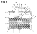
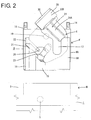
- the male connector M is configured to include a total of three connector accommodating portions arranged side by side in a width direction and entirely mounted on an end part of a printed circuit board 3. Only the connector accommodating portion in a center is mainly shown in FIG. 2 and other figures. This connector accommodating portion in the center is referred to as a male connector housing 1 (second connector housing) below.
- the male connector housing 1 is made of synthetic resin and includes a receptacle 2 in the form of a rectangular tube into which a female connector F is fittable.
- a receptacle 2 in the form of a rectangular tube into which a female connector F is fittable.
- One end sides of a plurality of male terminal fittings 4 formed into tabs project into the receptacle 2 and are accommodated while being arranged side by side in a height direction and the width direction.
- Each male terminal fitting 4 is held on a back wall of the receptacle 2 by being press-fitted.
- the other end sides of the male terminal fittings 4 project out from the receptacle 2.
- the other end sides are bent substantially at a right angle at intermediate positions and the other ends are inserted into through holes formed to penetrate through the printed circuit board 3 and connected to conduction paths formed on the printed circuit board 3 by soldering.
- a cam follower 5 is formed to project inwardly on a ceiling wall 2A of the receptacle 2.
- a releasing rib 7 is formed to project inwardly near the cam follower 5 on the ceiling wall 2A of the receptacle 2.
- the releasing rib 7 functions to release a state where a lever 6 is held at an initial position.
- This releasing rib 7 is formed from an opening edge to the back wall of the receptacle 2 and extends in a connecting direction of the male and female connectors F, M. Further, a tapered pressing surface 7A is formed on the tip of the releasing rib 7.
- the female connector F includes a female connector housing 8 (first connector housing) made of synthetic resin.
- the female connector housing 8 is formed into a block fittable into the receptacle 2.
- the female connector housing 8 is integrally structured from a main body portion 8A and a lever accommodating portion 8B arranged on one side (upper side in FIG. 1 ) of this main body portion 8A as shown in FIG. 1 .
- the main body portion 8A is formed with a plurality of cavities 9 for accommodating the female terminal fittings 10.
- the cavities 9 are arranged side by side in the height and width directions.
- each cavity 9 is formed to penetrate in the connecting direction of the male and female connectors M, F and each female terminal fitting 10 is mounted on a leading end part of each wire and accommodated into the cavity 9 from behind.
- a deflectable locking lance 11 is formed in each cavity 9 and locks the female terminal fitting 10.
- a retainer 12 is mounted into the female connector housing 8. The retainer 12 locks each female terminal fitting 10 to doubly retain the female terminal fitting 10 together with the locking lance 11 described above.
- mounting claws 14 for a wire cover 13 are provided on four corner parts and in widthwise centers of upper and lower edge parts, i.e. at a total of six positions, on a back surface side of the main body portion 8A. Each mounting claw 14 projects backward in the connecting direction from the rear surface of the main body portion 8A.
- the wire cover 13 is for correcting the respective wires pulled out from the rear surface of the female connector housing 8 in a set draw-out direction, and the respective wires are bundled, tapered and held at an exit part of the wire cover 13.
- the lever accommodating portion 8B is integrally formed substantially over the entire surface thereof on the shown upper surface side of the main body portion 8A, and the lever 6 to be described later is rotatably mounted therein.
- the lever accommodating portion 8B is formed into a hollow frame open backward in the connecting direction.
- an introducing opening 15 for introducing the cam follower 5 on the side of the male connector M into the lever accommodating portion 8B is open on the lever accommodating portion 8B. This introducing opening 15 is open from the front surface of the lever accommodating portion 8B in the connecting direction to the upper surface, and extends backward along the connecting direction on the upper surface.
- an entrance groove 16 into which the releasing rib 7 on the side of the male connector M is to be introduced is open near an end part of the lever accommodating portion 8B.
- This entrance groove 16 is also open from the front surface of the lever accommodating portion 8B in the connecting direction to the upper surface, and extends further backward than the introducing opening 15 substantially in parallel to the introducing opening 15 on the upper surface.
- the upper surface of the lever accommodating portion 8B is cut to form an escaping portion 17 for avoiding interference with the lever 6.
- the lever 6 is also integrally made of synthetic resin.
- the lever 6 is substantially in the form of a plate which can be accommodated into the lever accommodating portion 8B and mounted rotatably about a rotary shaft 19 on a bottom surface (outer surface 18 of the main body portion 8A) in the lever accommodating portion 8B.
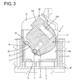
- a locking arm 21 is formed on a peripheral edge part of the lever 6 via a slit 20 and deflectable toward the slit 20. As shown in FIG. 3 , the locking arm 21 extends toward a side wall in the lever accommodating portion 8B and a tip part thereof can be locked to a locking protrusion 22 formed to project on the side wall in the lever accommodating portion 8B. By locking the locking arm 21 to the locking protrusion 22, the lever 6 is held in a state where rotation in a clockwise direction shown in FIG. 3 is regulated. The position of the lever 6 shown in FIG. 3 is referred to as the initial position below.
- the lever 6 is formed with a cam groove 23 and one end (entrance) of the cam groove 23 is open on the peripheral edge part of the lever 6.
- one end side of the cam groove 23 is exposed at an intermediate position of the introducing opening 15 of the lever accommodating portion 8B.
- the opening (entrance) of the cam groove 23 is facing forward in the connecting direction. This enables the cam follower 5 to enter the entrance of the cam groove 23 when the male and female connectors M, F are lightly fitted with the lever 6 held at the initial position.
- the lever 6 is formed with a lock arm 24.
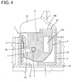
- This lock arm 24 functions to hold the lever 50 at a rotational position (hereinafter, this position is referred to as a connection end position; position shown in FIG. 4 ) by being locked to the lever accommodating portion 8B when the male and female connectors M, F are properly connected by rotating the lever 6 from the initial position.
- the lock arm 24 is arranged in a region opposite to the locking arm 21 and the cam groove 23 across the rotary shaft 19 of the lever 6.
- the lock arm 24 includes an arm portion 24A extending in a cantilever manner from a position near one side of the lever 6 as a supporting point toward the peripheral edge part on the other side, and deflectable in a direction away from the outer surface 18 of the main body portion 8A.
- the lock arm 24 is in such a posture that a longitudinal direction thereof is oblique to the connecting direction as shown in FIG. 3 when the lever 6 is at the initial position, but in such a posture that the longitudinal direction is parallel to the connecting direction as shown in FIG. 4 when the lever 6 is at the connection end position.
- a lock protrusion 25 is formed to project in a longitudinal central part on the underside (side facing the outer surface 18 of the main body portion 8A) of the arm portion 24A.
- a locking projecting edge 26 is formed to project on the bottom surface (outer surface 18 of the main body portion 8A) in the lever accommodating portion 8B.
- This locking projecting edge 26 is formed to have a predetermined width in a direction substantially orthogonal to the connecting direction although not shown in detail and regulates the rotation of the lever 6 in a direction to return to the initial position and the separation of the male and female connectors M, F by being locked to the lock protrusion 25 of the lever 6 when the lever 6 is at the connection end position.
- a height space to allow deflection necessary to release the locking of the locking projecting edge 26 and the lock protrusion 25 is defined between the ceiling surface of the lever accommodating portion 8B and the arm portion 24A.
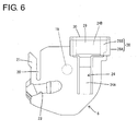
- an operating portion 24B wider than the arm portion 24A is formed on a free end side of the arm portion 24A.
- the operating portion 24B is formed to stand obliquely in a direction away from the outer surface 18 of the main body portion 8A.
- the underside of the operating portion 24B (surface facing the outer surface 18 of the main body portion 8A) serves as a first pinching surface 27 for lock release.
- the first pinching surface 27 partly projects backward from the lever accommodating portion 8B (female connector F) when the lever 6 is at the connection end position. A projection length necessary for finger placement is ensured.
- the lever 6 is formed with an arched protecting portion 28 for covering the entire operating portion 24B from a side facing the operating portion 24B in a deflecting direction of the operating portion 24B.
- the protecting portion 28 is composed of a pair of side walls 28A at opposite widthwise sides of the operating portion 24B and a coupling wall 28B coupling the upper ends of the both side walls 28A.
- the protecting portion 28 also projects outwardly from the rear end of the female connector F similarly to the operating portion 24B when the lever 6 is at the connection end position.
- the rear ends of the both side walls 28A and the coupling wall 28B are substantially flush with the rear end edge of the operating portion 24B.
- the coupling wall 28B is located above (right above) the operating portion 24B in a deflecting direction of the lock arm 24, and a second pinching surface 29 is formed on the upper surface.
- the arm portion 24A is deflected by pinching the first and second pinching surfaces 27, 29 from vertical sides.
- a distance between the coupling wall 28B and the operating portion 24B is set to allow the deflection of the arm portion 24 necessary for lock release.
- a finger placing edge 30 is formed to project upwardly on the rear end of the second pinching surface 29 for anti-slip purpose during a pinching operation.
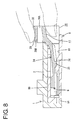
- the male and female connectors M, F can be connected with a small connecting force while being subjected to a force multiplying action by the lever 6.
- the lever 6 reaches the connection end position shown in FIG. 4 , the arm portion 24A of the lock arm 24 is deflected and deformed upwardly, whereby the lock protrusion 25 moves over the locking projecting edge 26 and resiliently returns. In this way, the lever 6 is locked at the connection end position and, in addition, the male and female connectors M, F are held in a properly connected state, with the result that the male and female terminal fittings 4, 10 are also properly connected as shown in FIG. 5 .
Landscapes
- Details Of Connecting Devices For Male And Female Coupling (AREA)
Applications Claiming Priority (2)
| Application Number | Priority Date | Filing Date | Title |
|---|---|---|---|
| JP2013224436A JP5979498B2 (ja) | 2013-10-29 | 2013-10-29 | レバー式コネクタ |
| PCT/JP2014/076951 WO2015064322A1 (fr) | 2013-10-29 | 2014-10-08 | Connecteur du type à levier |
Publications (3)
| Publication Number | Publication Date |
|---|---|
| EP3065231A1 true EP3065231A1 (fr) | 2016-09-07 |
| EP3065231A4 EP3065231A4 (fr) | 2016-10-19 |
| EP3065231B1 EP3065231B1 (fr) | 2018-03-21 |
Family
ID=53003933
Family Applications (1)
| Application Number | Title | Priority Date | Filing Date |
|---|---|---|---|
| EP14858983.1A Active EP3065231B1 (fr) | 2013-10-29 | 2014-10-08 | Connecteur du type à levier |
Country Status (5)
| Country | Link |
|---|---|
| US (1) | US9705251B2 (fr) |
| EP (1) | EP3065231B1 (fr) |
| JP (1) | JP5979498B2 (fr) |
| CN (1) | CN105684231B (fr) |
| WO (1) | WO2015064322A1 (fr) |
Families Citing this family (6)
| Publication number | Priority date | Publication date | Assignee | Title |
|---|---|---|---|---|
| JP6332074B2 (ja) * | 2015-02-16 | 2018-05-30 | 住友電装株式会社 | レバー式コネクタ |
| JP6222176B2 (ja) | 2015-07-08 | 2017-11-01 | 住友電装株式会社 | 電線カバー付きコネクタ |
| JP6607403B2 (ja) * | 2016-06-17 | 2019-11-20 | 住友電装株式会社 | レバー式コネクタ |
| JP6618509B2 (ja) * | 2017-06-06 | 2019-12-11 | 矢崎総業株式会社 | レバー式コネクタ |
| JP6927108B2 (ja) * | 2018-03-23 | 2021-08-25 | 住友電装株式会社 | レバー式コネクタ |
| JP7290116B2 (ja) | 2020-01-13 | 2023-06-13 | 住友電装株式会社 | コネクタ |
Family Cites Families (8)
| Publication number | Priority date | Publication date | Assignee | Title |
|---|---|---|---|---|
| JP2003249303A (ja) * | 2002-02-26 | 2003-09-05 | Sumitomo Wiring Syst Ltd | レバー式コネクタ |
| JP3987737B2 (ja) | 2002-02-26 | 2007-10-10 | 住友電装株式会社 | レバー式コネクタ |
| JP4066965B2 (ja) * | 2004-02-24 | 2008-03-26 | 住友電装株式会社 | コネクタ |
| JP2008112613A (ja) * | 2006-10-30 | 2008-05-15 | Sumitomo Wiring Syst Ltd | レバー式コネクタ |
| JP5029872B2 (ja) * | 2006-12-19 | 2012-09-19 | 住友電装株式会社 | レバー式コネクタ |
| JP5347936B2 (ja) * | 2009-12-10 | 2013-11-20 | 住友電装株式会社 | レバー式コネクタ |
| JP2011129419A (ja) * | 2009-12-18 | 2011-06-30 | Sumitomo Wiring Syst Ltd | レバー式コネクタ |
| JP2011134661A (ja) | 2009-12-25 | 2011-07-07 | Tyco Electronics Japan Kk | レバー式電気コネクタ |
-
2013
- 2013-10-29 JP JP2013224436A patent/JP5979498B2/ja active Active
-
2014
- 2014-10-08 EP EP14858983.1A patent/EP3065231B1/fr active Active
- 2014-10-08 WO PCT/JP2014/076951 patent/WO2015064322A1/fr active Application Filing
- 2014-10-08 CN CN201480059271.2A patent/CN105684231B/zh active Active
- 2014-10-08 US US15/032,369 patent/US9705251B2/en active Active
Also Published As
| Publication number | Publication date |
|---|---|
| US9705251B2 (en) | 2017-07-11 |
| JP2015088274A (ja) | 2015-05-07 |
| WO2015064322A1 (fr) | 2015-05-07 |
| US20160261069A1 (en) | 2016-09-08 |
| CN105684231A (zh) | 2016-06-15 |
| EP3065231A4 (fr) | 2016-10-19 |
| EP3065231B1 (fr) | 2018-03-21 |
| JP5979498B2 (ja) | 2016-08-24 |
| CN105684231B (zh) | 2017-10-24 |
Similar Documents
| Publication | Publication Date | Title |
|---|---|---|
| EP3065231B1 (fr) | Connecteur du type à levier | |
| KR101233567B1 (ko) | 접속 보조부를 갖는 전기 커넥터 조립체 | |
| JP4638557B2 (ja) | コネクタ位置決め素子およびこれを組み込んだコネクタ組立装置 | |
| EP2523266A1 (fr) | Connecteur de type levier | |
| US9276352B2 (en) | Connector and connector assembly provided therewith | |
| US9257789B2 (en) | Connector with force multiplying mechanism and connector assembly provided therewith | |
| US9124033B2 (en) | Lever-type connector | |
| EP1672747A1 (fr) | Connecteur | |
| US20150318639A1 (en) | Lever-type connector | |
| JP5945964B2 (ja) | コネクタ | |
| JP5939470B2 (ja) | コネクタ | |
| US9287662B2 (en) | Connector with force multiplying mechanism | |
| US9614314B2 (en) | Connector with a deflectable locking lance exposed on an outer surface of a housing | |
| US9722347B2 (en) | Connector with housings held in an assembled state by externally exposed locks at positions to be gripped for connection to or separation from a mating housing | |
| US8814588B2 (en) | Electrical connector with locking portions for an inserting component | |
| JP2011142050A (ja) | レバー式コネクタ | |
| US9698517B2 (en) | Connector with a wire cover having an opening for arranging wires pulled out from a housing of the connector | |
| US8337255B2 (en) | Connector and series of connectors | |
| JP2008177096A (ja) | コネクタのロック機構 | |
| EP1916746A2 (fr) | Connecteur | |
| EP3139451A1 (fr) | Connecteur, ensemble connecteur et son procédé d'assemblage | |
| US11784431B2 (en) | Connector with terminal fitting and lock arm | |
| EP4054015A1 (fr) | Connecteur | |
| JP2008060029A (ja) | レバー式コネクタ | |
| US20220059962A1 (en) | Connector |
Legal Events
| Date | Code | Title | Description |
|---|---|---|---|
| PUAI | Public reference made under article 153(3) epc to a published international application that has entered the european phase |
Free format text: ORIGINAL CODE: 0009012 |
|
| 17P | Request for examination filed |
Effective date: 20160414 |
|
| AK | Designated contracting states |
Kind code of ref document: A1 Designated state(s): AL AT BE BG CH CY CZ DE DK EE ES FI FR GB GR HR HU IE IS IT LI LT LU LV MC MK MT NL NO PL PT RO RS SE SI SK SM TR |
|
| AX | Request for extension of the european patent |
Extension state: BA ME |
|
| A4 | Supplementary search report drawn up and despatched |
Effective date: 20160921 |
|
| RIC1 | Information provided on ipc code assigned before grant |
Ipc: H01R 13/629 20060101AFI20160915BHEP |
|
| DAX | Request for extension of the european patent (deleted) | ||
| 17Q | First examination report despatched |
Effective date: 20170413 |
|
| GRAP | Despatch of communication of intention to grant a patent |
Free format text: ORIGINAL CODE: EPIDOSNIGR1 |
|
| INTG | Intention to grant announced |
Effective date: 20171102 |
|
| GRAS | Grant fee paid |
Free format text: ORIGINAL CODE: EPIDOSNIGR3 |
|
| GRAA | (expected) grant |
Free format text: ORIGINAL CODE: 0009210 |
|
| AK | Designated contracting states |
Kind code of ref document: B1 Designated state(s): AL AT BE BG CH CY CZ DE DK EE ES FI FR GB GR HR HU IE IS IT LI LT LU LV MC MK MT NL NO PL PT RO RS SE SI SK SM TR |
|
| REG | Reference to a national code |
Ref country code: GB Ref legal event code: FG4D |
|
| REG | Reference to a national code |
Ref country code: CH Ref legal event code: EP |
|
| REG | Reference to a national code |
Ref country code: AT Ref legal event code: REF Ref document number: 982057 Country of ref document: AT Kind code of ref document: T Effective date: 20180415 |
|
| REG | Reference to a national code |
Ref country code: IE Ref legal event code: FG4D |
|
| REG | Reference to a national code |
Ref country code: DE Ref legal event code: R096 Ref document number: 602014022813 Country of ref document: DE |
|
| REG | Reference to a national code |
Ref country code: NL Ref legal event code: MP Effective date: 20180321 |
|
| PG25 | Lapsed in a contracting state [announced via postgrant information from national office to epo] |
Ref country code: CY Free format text: LAPSE BECAUSE OF FAILURE TO SUBMIT A TRANSLATION OF THE DESCRIPTION OR TO PAY THE FEE WITHIN THE PRESCRIBED TIME-LIMIT Effective date: 20180321 Ref country code: HR Free format text: LAPSE BECAUSE OF FAILURE TO SUBMIT A TRANSLATION OF THE DESCRIPTION OR TO PAY THE FEE WITHIN THE PRESCRIBED TIME-LIMIT Effective date: 20180321 Ref country code: LT Free format text: LAPSE BECAUSE OF FAILURE TO SUBMIT A TRANSLATION OF THE DESCRIPTION OR TO PAY THE FEE WITHIN THE PRESCRIBED TIME-LIMIT Effective date: 20180321 Ref country code: FI Free format text: LAPSE BECAUSE OF FAILURE TO SUBMIT A TRANSLATION OF THE DESCRIPTION OR TO PAY THE FEE WITHIN THE PRESCRIBED TIME-LIMIT Effective date: 20180321 Ref country code: NO Free format text: LAPSE BECAUSE OF FAILURE TO SUBMIT A TRANSLATION OF THE DESCRIPTION OR TO PAY THE FEE WITHIN THE PRESCRIBED TIME-LIMIT Effective date: 20180621 |
|
| REG | Reference to a national code |
Ref country code: LT Ref legal event code: MG4D |
|
| REG | Reference to a national code |
Ref country code: AT Ref legal event code: MK05 Ref document number: 982057 Country of ref document: AT Kind code of ref document: T Effective date: 20180321 |
|
| PG25 | Lapsed in a contracting state [announced via postgrant information from national office to epo] |
Ref country code: BG Free format text: LAPSE BECAUSE OF FAILURE TO SUBMIT A TRANSLATION OF THE DESCRIPTION OR TO PAY THE FEE WITHIN THE PRESCRIBED TIME-LIMIT Effective date: 20180621 Ref country code: SE Free format text: LAPSE BECAUSE OF FAILURE TO SUBMIT A TRANSLATION OF THE DESCRIPTION OR TO PAY THE FEE WITHIN THE PRESCRIBED TIME-LIMIT Effective date: 20180321 Ref country code: RS Free format text: LAPSE BECAUSE OF FAILURE TO SUBMIT A TRANSLATION OF THE DESCRIPTION OR TO PAY THE FEE WITHIN THE PRESCRIBED TIME-LIMIT Effective date: 20180321 Ref country code: GR Free format text: LAPSE BECAUSE OF FAILURE TO SUBMIT A TRANSLATION OF THE DESCRIPTION OR TO PAY THE FEE WITHIN THE PRESCRIBED TIME-LIMIT Effective date: 20180622 Ref country code: LV Free format text: LAPSE BECAUSE OF FAILURE TO SUBMIT A TRANSLATION OF THE DESCRIPTION OR TO PAY THE FEE WITHIN THE PRESCRIBED TIME-LIMIT Effective date: 20180321 |
|
| REG | Reference to a national code |
Ref country code: FR Ref legal event code: PLFP Year of fee payment: 5 |
|
| PG25 | Lapsed in a contracting state [announced via postgrant information from national office to epo] |
Ref country code: EE Free format text: LAPSE BECAUSE OF FAILURE TO SUBMIT A TRANSLATION OF THE DESCRIPTION OR TO PAY THE FEE WITHIN THE PRESCRIBED TIME-LIMIT Effective date: 20180321 Ref country code: NL Free format text: LAPSE BECAUSE OF FAILURE TO SUBMIT A TRANSLATION OF THE DESCRIPTION OR TO PAY THE FEE WITHIN THE PRESCRIBED TIME-LIMIT Effective date: 20180321 Ref country code: RO Free format text: LAPSE BECAUSE OF FAILURE TO SUBMIT A TRANSLATION OF THE DESCRIPTION OR TO PAY THE FEE WITHIN THE PRESCRIBED TIME-LIMIT Effective date: 20180321 Ref country code: PL Free format text: LAPSE BECAUSE OF FAILURE TO SUBMIT A TRANSLATION OF THE DESCRIPTION OR TO PAY THE FEE WITHIN THE PRESCRIBED TIME-LIMIT Effective date: 20180321 Ref country code: AL Free format text: LAPSE BECAUSE OF FAILURE TO SUBMIT A TRANSLATION OF THE DESCRIPTION OR TO PAY THE FEE WITHIN THE PRESCRIBED TIME-LIMIT Effective date: 20180321 Ref country code: ES Free format text: LAPSE BECAUSE OF FAILURE TO SUBMIT A TRANSLATION OF THE DESCRIPTION OR TO PAY THE FEE WITHIN THE PRESCRIBED TIME-LIMIT Effective date: 20180321 Ref country code: IT Free format text: LAPSE BECAUSE OF FAILURE TO SUBMIT A TRANSLATION OF THE DESCRIPTION OR TO PAY THE FEE WITHIN THE PRESCRIBED TIME-LIMIT Effective date: 20180321 |
|
| PG25 | Lapsed in a contracting state [announced via postgrant information from national office to epo] |
Ref country code: AT Free format text: LAPSE BECAUSE OF FAILURE TO SUBMIT A TRANSLATION OF THE DESCRIPTION OR TO PAY THE FEE WITHIN THE PRESCRIBED TIME-LIMIT Effective date: 20180321 Ref country code: SM Free format text: LAPSE BECAUSE OF FAILURE TO SUBMIT A TRANSLATION OF THE DESCRIPTION OR TO PAY THE FEE WITHIN THE PRESCRIBED TIME-LIMIT Effective date: 20180321 Ref country code: SK Free format text: LAPSE BECAUSE OF FAILURE TO SUBMIT A TRANSLATION OF THE DESCRIPTION OR TO PAY THE FEE WITHIN THE PRESCRIBED TIME-LIMIT Effective date: 20180321 Ref country code: CZ Free format text: LAPSE BECAUSE OF FAILURE TO SUBMIT A TRANSLATION OF THE DESCRIPTION OR TO PAY THE FEE WITHIN THE PRESCRIBED TIME-LIMIT Effective date: 20180321 |
|
| PG25 | Lapsed in a contracting state [announced via postgrant information from national office to epo] |
Ref country code: PT Free format text: LAPSE BECAUSE OF FAILURE TO SUBMIT A TRANSLATION OF THE DESCRIPTION OR TO PAY THE FEE WITHIN THE PRESCRIBED TIME-LIMIT Effective date: 20180723 |
|
| REG | Reference to a national code |
Ref country code: DE Ref legal event code: R097 Ref document number: 602014022813 Country of ref document: DE |
|
| PLBE | No opposition filed within time limit |
Free format text: ORIGINAL CODE: 0009261 |
|
| STAA | Information on the status of an ep patent application or granted ep patent |
Free format text: STATUS: NO OPPOSITION FILED WITHIN TIME LIMIT |
|
| PG25 | Lapsed in a contracting state [announced via postgrant information from national office to epo] |
Ref country code: DK Free format text: LAPSE BECAUSE OF FAILURE TO SUBMIT A TRANSLATION OF THE DESCRIPTION OR TO PAY THE FEE WITHIN THE PRESCRIBED TIME-LIMIT Effective date: 20180321 |
|
| 26N | No opposition filed |
Effective date: 20190102 |
|
| REG | Reference to a national code |
Ref country code: DE Ref legal event code: R119 Ref document number: 602014022813 Country of ref document: DE |
|
| PG25 | Lapsed in a contracting state [announced via postgrant information from national office to epo] |
Ref country code: SI Free format text: LAPSE BECAUSE OF FAILURE TO SUBMIT A TRANSLATION OF THE DESCRIPTION OR TO PAY THE FEE WITHIN THE PRESCRIBED TIME-LIMIT Effective date: 20180321 |
|
| REG | Reference to a national code |
Ref country code: CH Ref legal event code: PL |
|
| GBPC | Gb: european patent ceased through non-payment of renewal fee |
Effective date: 20181008 |
|
| REG | Reference to a national code |
Ref country code: BE Ref legal event code: MM Effective date: 20181031 |
|
| PG25 | Lapsed in a contracting state [announced via postgrant information from national office to epo] |
Ref country code: MC Free format text: LAPSE BECAUSE OF FAILURE TO SUBMIT A TRANSLATION OF THE DESCRIPTION OR TO PAY THE FEE WITHIN THE PRESCRIBED TIME-LIMIT Effective date: 20180321 Ref country code: LU Free format text: LAPSE BECAUSE OF NON-PAYMENT OF DUE FEES Effective date: 20181008 |
|
| REG | Reference to a national code |
Ref country code: IE Ref legal event code: MM4A |
|
| PG25 | Lapsed in a contracting state [announced via postgrant information from national office to epo] |
Ref country code: DE Free format text: LAPSE BECAUSE OF NON-PAYMENT OF DUE FEES Effective date: 20190501 |
|
| PG25 | Lapsed in a contracting state [announced via postgrant information from national office to epo] |
Ref country code: CH Free format text: LAPSE BECAUSE OF NON-PAYMENT OF DUE FEES Effective date: 20181031 Ref country code: BE Free format text: LAPSE BECAUSE OF NON-PAYMENT OF DUE FEES Effective date: 20181031 Ref country code: LI Free format text: LAPSE BECAUSE OF NON-PAYMENT OF DUE FEES Effective date: 20181031 |
|
| PG25 | Lapsed in a contracting state [announced via postgrant information from national office to epo] |
Ref country code: GB Free format text: LAPSE BECAUSE OF NON-PAYMENT OF DUE FEES Effective date: 20181008 Ref country code: IE Free format text: LAPSE BECAUSE OF NON-PAYMENT OF DUE FEES Effective date: 20181008 |
|
| PG25 | Lapsed in a contracting state [announced via postgrant information from national office to epo] |
Ref country code: MT Free format text: LAPSE BECAUSE OF NON-PAYMENT OF DUE FEES Effective date: 20181008 |
|
| PG25 | Lapsed in a contracting state [announced via postgrant information from national office to epo] |
Ref country code: TR Free format text: LAPSE BECAUSE OF FAILURE TO SUBMIT A TRANSLATION OF THE DESCRIPTION OR TO PAY THE FEE WITHIN THE PRESCRIBED TIME-LIMIT Effective date: 20180321 |
|
| PG25 | Lapsed in a contracting state [announced via postgrant information from national office to epo] |
Ref country code: HU Free format text: LAPSE BECAUSE OF FAILURE TO SUBMIT A TRANSLATION OF THE DESCRIPTION OR TO PAY THE FEE WITHIN THE PRESCRIBED TIME-LIMIT; INVALID AB INITIO Effective date: 20141008 Ref country code: MK Free format text: LAPSE BECAUSE OF NON-PAYMENT OF DUE FEES Effective date: 20180321 |
|
| PG25 | Lapsed in a contracting state [announced via postgrant information from national office to epo] |
Ref country code: IS Free format text: LAPSE BECAUSE OF FAILURE TO SUBMIT A TRANSLATION OF THE DESCRIPTION OR TO PAY THE FEE WITHIN THE PRESCRIBED TIME-LIMIT Effective date: 20180721 |
|
| P01 | Opt-out of the competence of the unified patent court (upc) registered |
Effective date: 20230517 |
|
| PGFP | Annual fee paid to national office [announced via postgrant information from national office to epo] |
Ref country code: FR Payment date: 20230911 Year of fee payment: 10 |