EP3061966B1 - Pumpe - Google Patents
Pumpe Download PDFInfo
- Publication number
- EP3061966B1 EP3061966B1 EP16154070.3A EP16154070A EP3061966B1 EP 3061966 B1 EP3061966 B1 EP 3061966B1 EP 16154070 A EP16154070 A EP 16154070A EP 3061966 B1 EP3061966 B1 EP 3061966B1
- Authority
- EP
- European Patent Office
- Prior art keywords
- pump
- piston
- pig
- pump body
- pump according
- Prior art date
- Legal status (The legal status is an assumption and is not a legal conclusion. Google has not performed a legal analysis and makes no representation as to the accuracy of the status listed.)
- Active
Links
- 238000005086 pumping Methods 0.000 claims description 19
- 239000012530 fluid Substances 0.000 description 4
- 238000002485 combustion reaction Methods 0.000 description 2
- 238000007726 management method Methods 0.000 description 2
- 238000000034 method Methods 0.000 description 2
- 238000004140 cleaning Methods 0.000 description 1
- 230000001419 dependent effect Effects 0.000 description 1
- 238000005096 rolling process Methods 0.000 description 1
- 238000010079 rubber tapping Methods 0.000 description 1
Images


Classifications
-
- F—MECHANICAL ENGINEERING; LIGHTING; HEATING; WEAPONS; BLASTING
- F04—POSITIVE - DISPLACEMENT MACHINES FOR LIQUIDS; PUMPS FOR LIQUIDS OR ELASTIC FLUIDS
- F04B—POSITIVE-DISPLACEMENT MACHINES FOR LIQUIDS; PUMPS
- F04B1/00—Multi-cylinder machines or pumps characterised by number or arrangement of cylinders
- F04B1/12—Multi-cylinder machines or pumps characterised by number or arrangement of cylinders having cylinder axes coaxial with, or parallel or inclined to, main shaft axis
- F04B1/20—Multi-cylinder machines or pumps characterised by number or arrangement of cylinders having cylinder axes coaxial with, or parallel or inclined to, main shaft axis having rotary cylinder block
- F04B1/2014—Details or component parts
-
- B—PERFORMING OPERATIONS; TRANSPORTING
- B28—WORKING CEMENT, CLAY, OR STONE
- B28B—SHAPING CLAY OR OTHER CERAMIC COMPOSITIONS; SHAPING SLAG; SHAPING MIXTURES CONTAINING CEMENTITIOUS MATERIAL, e.g. PLASTER
- B28B15/00—General arrangement or layout of plant ; Industrial outlines or plant installations
-
- B—PERFORMING OPERATIONS; TRANSPORTING
- B28—WORKING CEMENT, CLAY, OR STONE
- B28B—SHAPING CLAY OR OTHER CERAMIC COMPOSITIONS; SHAPING SLAG; SHAPING MIXTURES CONTAINING CEMENTITIOUS MATERIAL, e.g. PLASTER
- B28B7/00—Moulds; Cores; Mandrels
- B28B7/24—Unitary mould structures with a plurality of moulding spaces, e.g. moulds divided into multiple moulding spaces by integratable partitions, mould part structures providing a number of moulding spaces in mutual co-operation
- B28B7/241—Detachable assemblies of mould parts providing only in mutual co-operation a number of complete moulding spaces
- B28B7/243—Detachable assemblies of mould parts providing only in mutual co-operation a number of complete moulding spaces for making plates, panels or similar sheet- or disc-shaped objects
-
- B—PERFORMING OPERATIONS; TRANSPORTING
- B66—HOISTING; LIFTING; HAULING
- B66C—CRANES; LOAD-ENGAGING ELEMENTS OR DEVICES FOR CRANES, CAPSTANS, WINCHES, OR TACKLES
- B66C17/00—Overhead travelling cranes comprising one or more substantially horizontal girders the ends of which are directly supported by wheels or rollers running on tracks carried by spaced supports
- B66C17/06—Overhead travelling cranes comprising one or more substantially horizontal girders the ends of which are directly supported by wheels or rollers running on tracks carried by spaced supports specially adapted for particular purposes, e.g. in foundries, forges; combined with auxiliary apparatus serving particular purposes
- B66C17/12—Overhead travelling cranes comprising one or more substantially horizontal girders the ends of which are directly supported by wheels or rollers running on tracks carried by spaced supports specially adapted for particular purposes, e.g. in foundries, forges; combined with auxiliary apparatus serving particular purposes for handling workpieces, e.g. ingots, which require to be supported temporarily within, or withdrawn from, a treatment chamber, e.g. tong cranes, soaking-pit cranes, stripper cranes
-
- F—MECHANICAL ENGINEERING; LIGHTING; HEATING; WEAPONS; BLASTING
- F04—POSITIVE - DISPLACEMENT MACHINES FOR LIQUIDS; PUMPS FOR LIQUIDS OR ELASTIC FLUIDS
- F04B—POSITIVE-DISPLACEMENT MACHINES FOR LIQUIDS; PUMPS
- F04B1/00—Multi-cylinder machines or pumps characterised by number or arrangement of cylinders
- F04B1/12—Multi-cylinder machines or pumps characterised by number or arrangement of cylinders having cylinder axes coaxial with, or parallel or inclined to, main shaft axis
- F04B1/20—Multi-cylinder machines or pumps characterised by number or arrangement of cylinders having cylinder axes coaxial with, or parallel or inclined to, main shaft axis having rotary cylinder block
-
- F—MECHANICAL ENGINEERING; LIGHTING; HEATING; WEAPONS; BLASTING
- F04—POSITIVE - DISPLACEMENT MACHINES FOR LIQUIDS; PUMPS FOR LIQUIDS OR ELASTIC FLUIDS
- F04B—POSITIVE-DISPLACEMENT MACHINES FOR LIQUIDS; PUMPS
- F04B1/00—Multi-cylinder machines or pumps characterised by number or arrangement of cylinders
- F04B1/12—Multi-cylinder machines or pumps characterised by number or arrangement of cylinders having cylinder axes coaxial with, or parallel or inclined to, main shaft axis
- F04B1/20—Multi-cylinder machines or pumps characterised by number or arrangement of cylinders having cylinder axes coaxial with, or parallel or inclined to, main shaft axis having rotary cylinder block
- F04B1/2014—Details or component parts
- F04B1/2035—Cylinder barrels
-
- F—MECHANICAL ENGINEERING; LIGHTING; HEATING; WEAPONS; BLASTING
- F04—POSITIVE - DISPLACEMENT MACHINES FOR LIQUIDS; PUMPS FOR LIQUIDS OR ELASTIC FLUIDS
- F04B—POSITIVE-DISPLACEMENT MACHINES FOR LIQUIDS; PUMPS
- F04B1/00—Multi-cylinder machines or pumps characterised by number or arrangement of cylinders
- F04B1/12—Multi-cylinder machines or pumps characterised by number or arrangement of cylinders having cylinder axes coaxial with, or parallel or inclined to, main shaft axis
- F04B1/20—Multi-cylinder machines or pumps characterised by number or arrangement of cylinders having cylinder axes coaxial with, or parallel or inclined to, main shaft axis having rotary cylinder block
- F04B1/2014—Details or component parts
- F04B1/2064—Housings
- F04B1/2071—Bearings for cylinder barrels
-
- F—MECHANICAL ENGINEERING; LIGHTING; HEATING; WEAPONS; BLASTING
- F04—POSITIVE - DISPLACEMENT MACHINES FOR LIQUIDS; PUMPS FOR LIQUIDS OR ELASTIC FLUIDS
- F04B—POSITIVE-DISPLACEMENT MACHINES FOR LIQUIDS; PUMPS
- F04B53/00—Component parts, details or accessories not provided for in, or of interest apart from, groups F04B1/00 - F04B23/00 or F04B39/00 - F04B47/00
- F04B53/16—Casings; Cylinders; Cylinder liners or heads; Fluid connections
-
- F—MECHANICAL ENGINEERING; LIGHTING; HEATING; WEAPONS; BLASTING
- F04—POSITIVE - DISPLACEMENT MACHINES FOR LIQUIDS; PUMPS FOR LIQUIDS OR ELASTIC FLUIDS
- F04B—POSITIVE-DISPLACEMENT MACHINES FOR LIQUIDS; PUMPS
- F04B9/00—Piston machines or pumps characterised by the driving or driven means to or from their working members
- F04B9/02—Piston machines or pumps characterised by the driving or driven means to or from their working members the means being mechanical
- F04B9/04—Piston machines or pumps characterised by the driving or driven means to or from their working members the means being mechanical the means being cams, eccentrics or pin-and-slot mechanisms
- F04B9/047—Piston machines or pumps characterised by the driving or driven means to or from their working members the means being mechanical the means being cams, eccentrics or pin-and-slot mechanisms the means being pin-and-slot mechanisms
Definitions
- the present invention relates to a pump, in particular a vollmolchbare pump.
- a rotor assembly is known for a rotor assembly consisting of two opposing rotor sections, which in an assembled state can move parallel to the axis of rotation.
- Each rotor section has continuous cylinders and a central passage for a drive shaft.
- Each rotor section defines inwardly projecting support legs and a rear surface that limits movement of the rotor section relative to the other.
- the rotor device can be used as an internal combustion engine, pump and compressor.
- a piggable piston pump which can be switched from “operation” to “pig”, wherein in the switching state “pig” the flow guidance within the pump from inlet to outlet has a circular cross-section and all changes in direction are arcuate. If the pump is switched to "Operation”, the pistons move and rotary valves control the pumping process.
- the invention has for its object to provide a fully piggable pump, which is robust with the simplest possible structure.
- the pump according to the invention has a pump housing with a pump head and a pump body. Pump head and pump body are located wholly or partly within the pump housing. In the pump head, two separate line sections are provided, each of which has connection openings at the end. Further, each conduit section in the pump head has a pumping port along the conduit section. The pump opening in the pump head is accessible from the pump body. The connection openings of the line sections correspond to openings in the pump housing.
- the pump body is rotatably mounted in the pump housing. Furthermore, the pump body has at least one piston guided in a piston guide, which is set back and forth in the axial direction via a piston drive during a rotational movement of the pump body.
- the piston guide is in a first rotational position of the pump body in connection with the pump opening of the first line section and in a second rotational position in connection with the pump opening of the second line section.
- the at least one piston of the pump according to the invention is advanced in an axially advanced position into a pig position, in which the at least one piston closes the pump opening of one of the line sections piggable.
- the piggable completion of the line section means that a pig can be used to clean the line section in the pump head and no area not accessible to the pig remains in the pump.
- the free end of the at least one piston has a depression which finally forms a closed inner contour in the line section with the pump opening.
- a pig pipe which connects two connection openings of different line sections with each other.
- the pig passes after passing through the first line section in the pig line.
- the pig enters the second line section in the pump in order to also molten it.
- the pig pipe is designed as a piggable line.
- the pig pipe is preferably provided with a piggable shut-off means, preferably a piggable ball valve.
- the shut-off means for the pigging operation is opened and the pig can pass through the pig pipe so as to clean the pipe sections of the pump head.
- the shut-off is closed and the line sections serve as a suction or discharge line.
- two pistons are provided, which are moved by the piston drive in a predetermined phase relationship to each other.
- the phase relationship is chosen so that one of the piston sucks and the other piston presses or vice versa.
- the piston drive periodically moves the pistons back and forth.
- the predetermined phase relationship results from the relative position of the pistons in the pump body.
- both pistons project out of their piston guide at the same height.
- the piston drive is provided with a circumferential groove in a soffit for the pump body.
- a drive pin of the piston is guided during a rotational movement of the pump body and thus set the position of the piston.
- the piston can be periodically moved back and forth with its drive pin.
- a detent is provided, with which the soffit in the pump housing in the pig position can be locked. Likewise, with the lock the soffit can be locked in the pump housing in an operating position.
- the pump body is connected to a pump shaft which protrudes with at least one end of the pump housing.
- the pump shaft is driven to rotate the pump body, causing the pistons to periodically pump over the piston drive.
- a slide is arranged on one of the line sections end facing away from the pump housing, which cooperates with the piston drive to push the piston or the piston with its line in the pig position or to pull into a pumping position.
- the slide can be designed as a hand slider or an automated slide.
- an overpressure protection for overpressure protection of the pump body is pressed by a spring assembly in a spring-biased position. In the spring-biased position, a pressure can be built up via the piston or pistons. When a predetermined maximum pressure value is exceeded, the pump body is pushed back against the spring force of the spring assembly and a gap is released. The gap is located between the pipe sections in the pump head and the pump body, so that no pressure can build up between the pump body and the pipe sections. If the pressure drops again, the pump body returns to its position sealed, spring-biased position and the pumping operation can be continued.
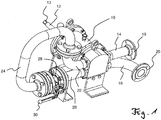
- Fig. 1 shows the pump 10 according to the invention, which is drivable via a pump shaft 12.
- the pump shaft 12 has at its free end a shaft-hub connection 13, on which a motor drive (not shown) or a hand crank (not shown) can be placed.
- the pump has two lines 14, 16, with their function as supply or discharge is not specified.
- the lines 14, 16 each have a connection flange 18, 20, which allows a connection to a piping system.
- the line 14 passes via a running in the pump line section in the connecting line 22, the already part of a pig pipe 24.
- the connecting line 26 opens into the pump 10 and is connected via a further line section to the line 16.
- a piggable ball valve 28 is provided, which can be opened and closed via a hand lever 30 or a rotary actuator.
- the ball valve 28 is closed in pumping operation and opened in the pigging operation.
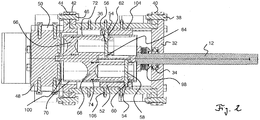
- Fig. 2 shows a cross section through the pump with a pump housing.
- the pump housing has a bottom 32 through which the pump shaft 12 is guided.
- the pump shaft 12 is mounted on a rolling bearing 34 in a pump bottom 32.
- the pump bottom 32 is connected to a pump wall 36.
- the pump wall 36 has a circular cylindrical shape and is fastened to the pump bottom 32 via a retaining ring 40 secured by a screw 38.
- a pump head 48 is provided which is secured by a pair of retaining rings 42, 44 and screws 46.
- the pump head 48 is disposed in an upper housing portion 50.
- a piston drive is provided, which has a soffit 52 with a circumferential groove 54.
- the groove 54 runs in a waveform, preferably sinusoidally in the interior of the pump wall 36 to.
- each have a drive pin 56 and 58 is provided in the circumferential groove 54 .
- the drive pins have a pin head 60 which dives into the groove 54 until a circumferential pin ring 62 rests on the inside of the soffit 52.
- the phase relationship between the pistons is determined by the relative position of the pistons in the pump body. In the illustrated example, pistons in the pump body are opposite each other, so that there is a phase difference of 180 °.
- the drive pin is guided by a piston body 66 and protrudes with a pin end 64 of this.
- Fig. 2 shows a sectional view of two piston bodies 66 and 68, which are each sealingly guided in a piston guide 70, 72 via an O-ring 74.
- the pump body rotates with the piston guides 70, 72.
- the soffit 52 is fixedly connected to the cylinder wall 36, so that the peg heads 60, 62 move in the groove 54. Due to the course of the groove 54, the piston body 66, 68 are moved back and forth in their piston guide. This creates a sucking and pushing movement.
- the piston body 66 and 68 are depending on the rotational position with line sections in the pump head in conjunction.
- Fig. 3 shows the pump head 48 with two line sections 76 and 78.
- the line sections 76, 78 are straight and parallel through the pump head 48 and open into the connection lines 14, 16, 22 and 26.
- the line sections 76 and 78 each have one Pump opening 80, 82.
- Fig. 3 shows a sectional view in which the pump body with the piston is in direct communication with the pumping ports 80, 82.
- the pumping process runs in this case so that a retracting piston body sucks a fluid from the associated line section and, after a 180 ° rotation of the pump body, the forwardly moving piston body presses the sucked-in fluid into the other line section. It follows, then, based on the line sections 76 and 78, the removal of a fluid from a line section into a pumping chamber 84, 86 and by the rotation of the pump body with the pump shaft, the delivery takes place after the rotational movement in the other line section.
- a slider 90 to advance a soffit bracket 92 in the direction of arrow A.
- the piston body are advanced. In the illustrated position of the piston body they are advanced at the same height parallel to each other in the pumping ports 80, 82 of the line sections 76, 78.
- Each piston body 66, 68 has at its free end a contour adapted to the diameter of the line sections 78, 76, so that the advanced piston bodies 66, 68 produce piggable line sections 76, 78.
- the pumping chambers 84 and 86 are also cleaned of residues which are pushed into the line sections 76 and 78. Here they can be cleaned by a pig shot through the pipe sections. For cleaning, the ball valve in the pig pipe is opened, so that the pig passes twice through the pump head.
- Fig. 4 shows a further cross section through the pump, in which a pump body 94 can be seen.
- the pump body 94 is rotatably connected to the pump shaft 12. Via a projecting pin 96, the pump body 94 is rotatably mounted in a pump head 48. It can be clearly seen that an annular gap is provided between soffit 52 and pump body 94.
- Fig. 5 shows a sectional view through the pump head 48 and the mutually parallel line sections 76, 78.
- the line sections 76, 78 have their pumping holes 80, 82, the center, in the sectional view Fig. 5 the view of the pump body 94 releases.
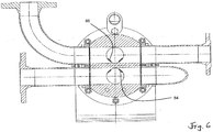
- Fig. 6 shows the pump body 94 in a slightly rotated position, so that the view of the pump chambers 84 and 86 is released through the pumping openings.
- the pump body 94 is resiliently mounted via a spring assembly 98.
- the spring assembly 98 is disposed on the pump shaft 12 and cooperates with the bottom 32 of the pump.
- the spring package 98 is in Fig. 2 shown in its compressed state in which the pump body 94 is pressed in the direction of the pump shaft. This creates a gap 100 between the pump body and the pump head 48.
- Fig. 3 shows the spring pack 98 in its spring-biased position. In this case, the pump body 94 is pressed against a seal 102. By the seal 102, the pumping chamber 84 of the piston body 68 is connected to the line section 76.
- a pressure or a negative pressure from the pumping chamber is thus passed on to the line section 76. Is in contrast the in Fig. 2 shown state, can not be pumped through the line sections, since the gap 100 prevents pressure build-up.
- the spring package 98 fulfills the task of overpressure protection. If, due to a fault, the pressure in one of the piston chambers or in one of the line sections is too great and above a maximum pressure value, a force is exerted on the piston and thus the pump body 94, so that the spring packet 98 is compressed against this force.
- a soffit holder 92 can be advanced in the direction A by the manual slide 90 in order to push the piston drive with the piston into a pig position.
- the closer structure for this is out Fig. 2 to recognize.
- the reveal 52 is arranged on a key 104.
- the key 104 is held by screws 106 in the pump wall 36.
- the soffit 52 of the piston drive is equipped with four circumferentially distributed grooves. In two of the grooves a soffit holder is arranged, which is displaceable over the manual slide 90 in the axial direction. In the other two grooves is how in Fig. 2 shown, a respective key 104 is arranged to ensure that the soffit does not rotate with the pump body.
Landscapes
- Engineering & Computer Science (AREA)
- Mechanical Engineering (AREA)
- General Engineering & Computer Science (AREA)
- Chemical & Material Sciences (AREA)
- Ceramic Engineering (AREA)
- Manufacturing & Machinery (AREA)
- Reciprocating Pumps (AREA)
- Details Of Reciprocating Pumps (AREA)
Description
- Die vorliegende Erfindung betrifft eine Pumpe, insbesondere eine vollmolchbare Pumpe. Aus
WO 2000/53893 - Aus
DE 33 18 232 ist eine molchbare Kolbenpumpe bekannt, die von "Betrieb" auf "Molchen" geschaltet werden kann, wobei im Schaltzustand "Molchen" die Strömungsführung innerhalb der Pumpe vom Eintritt bis zum Austritt einen kreisförmigen Querschnitt aufweist und alle Richtungsänderungen bogenförmig sind. Ist die Pumpe auf "Betrieb" geschaltet, so bewegen sich die Kolben und Drehschieber steuern den Pumpvorgang. - Aus
US 2003/00706233 - Aus
US 3,904,318 ist eine Axialkolbenpumpe bekannt, die einen drehenden Pumpenkörper aufweist. - Der Erfindung liegt die Aufgabe zugrunde, eine vollständig molchbare Pumpe bereitzustellen, die mit möglichst einfachem Aufbau robust ausgebildet ist.
- Erfindungsgemäß wird die Aufgabe durch eine Pumpe mit den Merkmalen aus Anspruch 1 gelöst. Vorteilhafte Ausgestaltungen bilden den Gegenstand der Unteransprüche.
- Die erfindungsgemäße Pumpe weist ein Pumpengehäuse mit einem Pumpenkopf und einem Pumpenkörper auf. Pumpenkopf und Pumpenkörper befinden sich ganz oder teilweise innerhalb des Pumpengehäuses. In dem Pumpenkopf sind zwei voneinander getrennte Leitungsabschnitte vorgesehen, von denen jeder endseitig Anschlussöffnungen besitzt. Ferner besitzt jeder Leitungsabschnitt in dem Pumpenkopf eine Pumpöffnung entlang dem Leitungsabschnitt. Die Pumpöffnung in dem Pumpenkopf ist vom Pumpenkörper aus zugänglich. Die Anschlussöffnungen der Leitungsabschnitte entsprechen Öffnungen in dem Pumpengehäuse. Bei der erfindungsgemäßen Pumpe ist der Pumpenkörper drehbar in dem Pumpengehäuse gelagert. Ferner weist der Pumpenkörper mindestens einen in einer Kolbenführung geführten Kolben auf, der über einen Kolbenantrieb bei einer Drehbewegung des Pumpenkörpers in axialer Richtung vor- und zurückgestellt wird. Die Kolbenführung ist in einer ersten Drehstellung des Pumpenkörpers in Verbindung mit der Pumpöffnung des ersten Leitungsabschnitts und in einer zweiten Drehstellung in Verbindung mit der Pumpöffnung des zweiten Leitungsabschnitts. Der mindestens eine Kolben der erfindungsgemäßen Pumpe ist in einer axial vorgeschobenen Position in eine Molchstellung vorgeschoben, in der der mindestens eine Kolben die Pumpöffnung eines der Leitungsabschnitte molchbar abschließt. Der molchbare Abschluss des Leitungsabschnitts bedeutet, dass zum Reinigen des Leitungsabschnitts in dem Pumpenkopf ein Molch eingesetzt werden kann und kein dem Molch nicht zugänglicher Bereich in der Pumpe verbleibt. Erfindungsgemäß besitzt für einen molchbaren Abschluss das freie Ende des mindestens einen Kolbens eine Vertiefung, die mit der Pumpöffnung abschließend eine geschlossene Innenkontur in dem Leitungsabschnitt bildet.
- In einer bevorzugten Ausgestaltung ist eine Molchleitung vorgesehen, die zwei Anschlussöffnungen von unterschiedlichen Leitungsabschnitten miteinander verbindet. Über die Molchleitung gelangt der Molch nach Durchfahren des ersten Leitungsabschnitts in die Molchleitung. Nach Durchlaufen der Molchleitung tritt der Molch in den zweiten Leitungsabschnitt in der Pumpe ein, um auch diesen zu molchen. Hierzu ist die Molchleitung als eine molchbare Leitung ausgebildet.
- Für einen Pumpenbetrieb mit der Pumpe ist die Molchleitung bevorzugt mit einem molchbaren Absperrmittel, bevorzugt einem molchbaren Kugelhahn versehen. Bei dieser Ausgestaltung wird das Absperrmittel für den Molchbetrieb geöffnet und der Molch kann die Molchleitung durchlaufen, um so die Leitungsabschnitte des Pumpenkopfes zu reinigen. Im Pumpenbetrieb ist das Absperrmittel verschlossen und die Leitungsabschnitte dienen als Saug- bzw. Druckleitung.
- In einer bevorzugten Ausgestaltung sind zwei Kolben vorgesehen, die durch den Kolbenantrieb in einer vorbestimmten Phasenbeziehung zueinander bewegt werden. Bevorzugt ist die Phasenbeziehung so gewählt, dass einer der Kolben saugt und der andere Kolben drückt bzw. umgekehrt. Der Kolbenantrieb bewegt die Kolben periodisch vor und zurück. Die vorbestimmte Phasenbeziehung ergibt sich aus der relativen Lage der Kolben in dem Pumpenkörper.
- In einer bevorzugten Ausgestaltung stehen in einer Molchstellung beide Kolben in gleicher Höhe aus ihrer Kolbenführung vor. So kann durch ein Vorschieben der Kolben mit ihrem Kolbenantrieb oder des Pumpenkörpers in Axialrichtung mit jedem freien Ende des Kolbens jeweils einer der Leitungsabschnitte molchbar verschlossen werden.
- In einer weiteren bevorzugten Ausgestaltung ist der Kolbenantrieb mit einer umlaufenden Nut in einer Laibung für den Pumpenkörper vorgesehen. In der umlaufenden Nut wird ein Antriebszapfen des Kolbens bei einer Drehbewegung des Pumpenkörpers geführt und damit die Position des Kolbens gestellt.
- Durch eine entsprechende, beispielsweise sinusoidale Form der Nut kann der Kolben mit seinem Antriebszapfen periodisch vor- und zurückbewegt werden.
- In einer bevorzugten Ausgestaltung ist eine Arretierung vorgesehen, mit der die Laibung in dem Pumpengehäuse in der Molchstellung arretierbar ist. Ebenso kann mit der Arretierung die Laibung auch in dem Pumpengehäuse in einer Betriebsstellung arretiert werden.
- In einer bevorzugten Ausgestaltung ist der Pumpenkörper mit einer Pumpenwelle verbunden, die mit mindestens einem Ende aus dem Pumpengehäuse vorsteht. Die Pumpenwelle wird angetrieben, um den Pumpenkörper zu drehen und dabei die Kolben über den Kolbenantrieb in eine periodische Pumpbewegung zu versetzen.
- In einer zweckmäßigen Ausgestaltung ist an einem von den Leitungsabschnitten fortweisenden Ende des Pumpengehäuses ein Schieber angeordnet, der mit dem Kolbenantrieb zusammenwirkt, um den oder die Kolben mit ihrer Leitung in die Molchstellung zu schieben oder in eine Pumpstellung zu ziehen. Der Schieber kann als Handschieber oder ein automatisierter Schieber ausgebildet sein.
- Bevorzugt liegt ebenfalls eine Überdrucksicherung vor. Zur Überdrucksicherung ist der Pumpenkörper durch ein Federpaket in eine federvorgespannte Position gedrückt. In der federvorgespannten Position kann über den oder die Kolben ein Druck aufgebaut werden. Bei einem Überschreiten eines vorbestimmten maximalen Druckwerts wird der Pumpenkörper gegen die Federkraft des Federpakets zurückgedrückt und es wird ein Spalt freigegeben. Der Spalt befindet sich zwischen den Leitungsabschnitten in dem Pumpenkopf und dem Pumpenkörper, so dass kein Druck sich zwischen dem Pumpenkörper und den Leitungsabschnitten aufbauen kann. Fällt der Druckwert wieder, so wird der Pumpenkörper wieder in seine abgedichtete, federvorgespannte Position gedrückt und der Pumpvorgang kann fortgesetzt werden.
- Eine bevorzugte Ausgestaltung der erfindungsgemäßen Pumpe wird anhand der nachfolgenden Figuren näher beschrieben. Es zeigen:
- Fig. 1
- die erfindungsgemäße Pumpe mit ihrer Molchleitung,
- Fig. 2
- eine Schnittansicht der Pumpe mit zwei Kolben in unterschiedlicher Stellung,
- Fig. 3
- eine andere Schnittansicht mit den Kolben in gleicher Stellung,
- Fig. 4
- eine weitere Schnittansicht durch die Pumpe ohne Ansichten der Kolben,
- Fig. 5
- eine Schnittansicht durch den Pumpenkopf und
- Fig. 6
- eine weitere Schnittansicht durch den Pumpenkopf bei gedrehtem Pumpenkörper.
-
Fig. 1 zeigt die erfindungsgemäße Pumpe 10, die über eine Pumpenwelle 12 antreibbar ist. Die Pumpenwelle 12 besitzt an ihrem freien Ende eine Welle-Nabe-Verbindung 13, auf den ein motorischer Antrieb (nicht dargestellt) oder eine Handkurbel (nicht dargestellt) aufgesetzt werden kann. Die Pumpe besitzt zwei Leitungen 14, 16, wobei deren Funktion als Zu- oder Ableitung nicht festgelegt ist. Die Leitungen 14, 16 besitzen jeweils einen Anschlussflansch 18, 20, der eine Anbindung an ein Rohrleitungssystem gestattet. Die Leitung 14 geht über einen in der Pumpe verlaufenden Leitungsabschnitt in die Anschlussleitung 22 über, die bereits Teil einer Molchleitung 24 ist. Die Anschlussleitung 26 mündet in der Pumpe 10 und ist über einen weiteren Leitungsabschnitt mit der Leitung 16 verbunden. In der Molchleitung 26 ist ein molchbarer Kugelhahn 28 vorgesehen, der über einen Handhebel 30 oder einen Schwenkantrieb geöffnet und geschlossen werden kann. - Wie später noch erläutert wird, ist im Pumpbetrieb der Kugelhahn 28 geschlossen und im Molchbetrieb geöffnet.
-
Fig. 2 zeigt einen Querschnitt durch die Pumpe mit einem Pumpengehäuse. Das Pumpengehäuse weist einen Boden 32 auf, durch den die Pumpenwelle 12 geführt ist. Die Pumpenwelle 12 ist über ein Wälzlager 34 in einem Pumpenboden 32 gelagert. Der Pumpenboden 32 ist mit einer Pumpenwand 36 verbunden. Die Pumpenwand 36 besitzt eine kreiszylindrische Form und ist über einen mit einer Schraube 38 gesicherten Haltering 40 an dem Pumpenboden 32 befestigt. An dem von dem Pumpenboden 32 fortweisenden Ende der Seitenwand 36 ist ein Pumpenkopf 48 vorgesehen, der über ein Paar von Halteringen 42, 44 und Schrauben 46 gesichert ist. - Der Pumpenkopf 48 ist in einem oberen Gehäuseabschnitt 50 angeordnet. Im Inneren der Pumpenwand 36 ist ein Kolbenantrieb vorgesehen, der eine Laibung 52 mit einer umlaufenden Nut 54 besitzt. Die Nut 54 läuft in einer Wellenform, bevorzugt sinusoidal im Inneren der Pumpenwand 36 um. In der umlaufenden Nut 54 ist jeweils ein Antriebszapfen 56 und 58 vorgesehen. Die Antriebszapfen besitzen einen Zapfenkopf 60, der in die Nut 54 taucht, bis ein umlaufender Zapfenring 62 auf der Innenseite der Laibung 52 aufliegt. Die Phasenbeziehung zwischen den Kolben wird durch die relative Lage der Kolben in dem Pumpenkörper bestimmt. In dem dargestellten Beispiel liegen Kolben in dem Pumpenkörper einander gegenüber, so dass eine Phasendifferenz von 180° vorliegt. Der Antriebszapfen ist durch einen Kolbenkörper 66 geführt und steht mit einem Zapfenende 64 aus diesem vor.
-
Fig. 2 zeigt eine Schnittansicht von zwei Kolbenkörpern 66 und 68, die jeweils in einer Kolbenführung 70, 72 über einen O-Ring 74 abdichtend geführt sind. Bei einer Drehung der Pumpenwelle 12 dreht sich der Pumpenkörper mit den Kolbenführungen 70, 72. Die Laibung 52 ist fest mit der Zylinderwand 36 verbunden, so dass sich die Zapfenköpfe 60, 62 in der Nut 54 bewegen. Durch den Verlauf der Nut 54 werden die Kolbenkörper 66, 68 in ihrer Kolbenführung vor- und zurückbewegt. Hierdurch entsteht eine saugende und drückende Bewegung. Die Kolbenkörper 66 und 68 stehen je nach Drehstellung mit Leitungsabschnitten im Pumpenkopf in Verbindung. -
Fig. 3 zeigt den Pumpenkopf 48 mit zwei Leitungsabschnitten 76 und 78. Die Leitungsabschnitte 76, 78 verlaufen gerade und parallel durch den Pumpenkopf 48 und münden in den Anschlussleitungen 14, 16, 22 und 26. Im Inneren des Pumpenkopfes 48 besitzen die Leitungsabschnitte 76 und 78 jeweils eine Pumpöffnung 80, 82.Fig. 3 zeigt eine Schnittansicht, bei der der Pumpenkörper mit den Kolben in direkter Verbindung zu den Pumpöffnungen 80, 82 steht. Durch eine Bewegung der Kolbenkörper 66 und 68 kann hier ein Fluid in die Leitungsabschnitte 76 und 78 gefördert bzw. aus diesen gesaugt werden. Der Pumpvorgang läuft hierbei so, dass ein sich zurückziehender Kolbenkörper aus dem zugehörigen Leitungsabschnitt ein Fluid saugt und nach einer 180°-Drehung des Pumpenkörpers der sich nach vorne bewegende Kolbenkörper das angesaugte Fluid in den anderen Leitungsabschnitt drückt. Es folgt also, bezogen auf die Leitungsabschnitte 76 und 78 die Entnahme eines Fluids aus einem Leitungsabschnitt in eine Pumpkammer 84, 86 und durch die Drehung des Pumpenkörpers mit der Pumpenwelle erfolgt die Abgabe nach der Drehbewegung in den anderen Leitungsabschnitt. - Für den Molchvorgang der Pumpe ist vorgesehen, die Arretiereinrichtung 88 in der Pumpenwand 36 zu lösen und über einen Schieber 90 eine Laibungshalterung 92 in Richtung des Pfeils A vorzuschieben. Durch den Vorschub der Laibung 52 über die Laibungshalterung 92 werden die Kolbenkörper vorgeschoben. In der dargestellten Position der Kolbenkörper werden diese auf gleicher Höhe parallel zueinander in die Pumpöffnungen 80, 82 der Leitungsabschnitte 76, 78 vorgeschoben. Jeder Kolbenkörper 66, 68 besitzt an seinem freien Ende eine an den Durchmesser der Leitungsabschnitte 78, 76 angepasste Kontur, so dass die vorgeschobenen Kolbenkörper 66, 68 molchbare Leitungsabschnitte 76, 78 erzeugen. Durch das mechanische Vorschieben der Kolben mit Hilfe des Schiebers 90 wird auch die Pumpkammer 84 und 86 von Rückständen gereinigt, die in die Leitungsabschnitte 76 und 78 geschoben werden. Hier können sie über einen durch die Leitungsabschnitte geschossenen Molch gereinigt werden. Für die Reinigung ist der Kugelhahn in der Molchleitung geöffnet, so dass der Molch insgesamt zweimal durch den Pumpenkopf durchtritt.
-
Fig. 4 zeigt einen weiteren Querschnitt durch die Pumpe, in dem ein Pumpenkörper 94 zu erkennen ist. Der Pumpenkörper 94 ist drehfest mit der Pumpenwelle 12 verbunden. Über einen vorstehenden Zapfen 96 ist der Pumpenkörper 94 in einem Pumpenkopf 48 drehbar gelagert. Deutlich zu erkennen ist, dass zwischen Laibung 52 und Pumpenkörper 94 ein Ringspalt vorgesehen ist. -
Fig. 5 zeigt eine Schnittansicht durch den Pumpenkopf 48 und die parallel zueinander verlaufenden Leitungsabschnitte 76, 78. Die Leitungsabschnitte 76, 78 besitzen mittig ihre Pumpöffnungen 80, 82, die in der Schnittansicht ausFig. 5 den Blick auf den Pumpenkörper 94 freigibt. -
Fig. 6 zeigt den Pumpenkörper 94 in einer leicht gedrehten Position, so dass durch die Pumpöffnungen der Blick auf die Pumpkammern 84 und 86 freigegeben ist. - Ein weiteres Merkmal der erfindungsgemäßen Pumpe besteht darin, dass der Pumpenkörper 94 über ein Federpaket 98 federnd gelagert ist. Wie in
Fig. 2 zu entnehmen, ist das Federpaket 98 auf der Pumpenwelle 12 angeordnet und wirkt mit dem Boden 32 der Pumpe zusammen. Das Federpaket 98 ist inFig. 2 in seinem komprimierten Zustand dargestellt, in dem der Pumpenkörper 94 in Richtung der Pumpenwelle gedrückt ist. Hierdurch entsteht ein Spalt 100 zwischen dem Pumpenkörper und dem Pumpenkopf 48.Fig. 3 zeigt das Federpaket 98 in seiner federvorgespannten Position. Hierbei wird der Pumpenkörper 94 gegen eine Dichtung 102 gedrückt. Durch die Dichtung 102 ist die Pumpkammer 84 des Kolbenkörpers 68 mit dem Leitungsabschnitt 76 verbunden. Ein Druck oder ein Unterdruck aus der Pumpkammer wird somit auf den Leitungsabschnitt 76 weitergegeben. Liegt dagegen der inFig. 2 dargestellte Zustand vor, kann über die Leitungsabschnitte nicht gepumpt werden, da der Spalt 100 einen Druckaufbau verhindert. Das Federpaket 98 erfüllt die Aufgabe einer Überdrucksicherung. Ist aufgrund eines Fehlers der Druck in einer der Kolbenkammern oder in einem der Leitungsabschnitte zu groß und oberhalb eines maximalen Druckwerts, wird eine Kraft auf den Kolben und damit den Pumpenkörper 94 ausgeübt, so dass gegen diese Kraft das Federpaket 98 komprimiert wird. - Wie vorstehend bereits erläutert, kann durch den Handschieber 90 eine Laibungshalterung 92 in Richtung A vorgeschoben werden, um den Kolbenantrieb mit dem Kolben in eine Molchstellung zu schieben. Der nähere Aufbau hierzu ist aus
Fig. 2 zu erkennen. Hier ist die Laibung 52 auf einer Passfeder 104 angeordnet. Die Passfeder 104 ist über Schrauben 106 in der Pumpenwand 36 gehalten. Berücksichtigt man, dass dieFign. 2 und3 unterschiedliche Querschnitte durch die Pumpe darstellen, ergibt sich insgesamt das folgende Bild, dass die Laibung 52 des Kolbenantriebs mit vier über den Umfang verteilten Nuten ausgestattet ist. In zwei der Nuten ist eine Laibungshalterung angeordnet, die über den Handschieber 90 in Axialrichtung verschieblich ist. In den beiden anderen Nuten ist, wie inFig. 2 dargestellt, jeweils ein Passfeder 104 angeordnet, um sicherzustellen, dass die Laibung sich nicht mit dem Pumpenkörper mitdreht. -
- 10
- Pumpe
- 12
- Pumpenwelle
- 13
- Welle-Nabe-Verbindung
- 14
- Leitung
- 16
- Leitung
- 18
- Anschlussflansch
- 20
- Anschlussflansch
- 22
- Anschlussleitung
- 24
- Molchleitung
- 26
- Anschlussleitung
- 28
- Kugelhahn
- 30
- Handhebel
- 32
- Boden
- 34
- Wälzlager
- 36
- Pumpenwand
- 38
- Schraube
- 40
- Haltering
- 42
- Haltering
- 44
- Haltering
- 46
- Schrauben
- 48
- Pumpenkopf
- 50
- Gehäuseabschnitt
- 52
- Laibung
- 54
- Nut
- 56
- Antriebszapfen
- 58
- Antriebszapfen
- 60
- Zapfenkopf
- 62
- Zapfenring
- 64
- Zapfenende
- 66
- Kolbenkörper
- 68
- Kolbenkörper
- 70
- Kolbenführung
- 72
- Kolbenführung
- 74
- O-Ring
- 76
- Leitungsabschnitt
- 78
- Leitungsabschnitt
- 80
- Pumpöffnung
- 82
- Pumpöffnung
- 84
- Pumpkammer
- 86
- Pumpkammer
- 88
- Arretiervorrichtung
- 90
- Handschieber
- 92
- Laibungshalterung
- 94
- Pumpenkörper
- 96
- Zapfen
- 98
- Federpaket
- 100
- Spalt
- 102
- Dichtung
- 104
- Passfeder
- 106
- Schraube
Claims (14)
- Pumpe (10), die- ein Pumpengehäuse mit einem Pumpenkopf (48) und einem Pumpenkörper (94) aufweist,- wobei der Pumpenkopf (48) zwei Leitungsabschnitte (76, 78) besitzt, von denen jeder endseitig Anschlussöffnungen und eine Pumpöffnung (80, 82) entlang dem Leitungsabschnitt (76, 78) besitzt,- und der Pumpenkörper (94) drehbar in dem Pumpengehäuse gelagert ist und mindestens einen in einer Kolbenführung in dem Pumpenkörper (94) geführten Kolben aufweist, der über eine Kolbenantrieb (54, 56, 58) bei einer Drehbewegung des Pumpenkörpers (48) in axialer Richtung vor- und zurückgestellt wird,- wobei die Kolbenführung in einer ersten Stellung des Pumpenkörpers (94) in Verbindung mit der Pumpöffnung (80) des ersten Leitungsabschnitts (76) und in einer zweiten Drehstellung in Verbindung mit der Pumpöffnung (82) des zweiten Leitungsabschnitts (78) steht, und- der mindestens eine Kolben in einer axial vorgeschobenen Position mindestens eine Molchstellung aufweist, in der der mindestens eine Kolben die Pumpöffnung (80, 82) eines der Leitungsabschnitte (76, 78) molchbar abschließt,dadurch gekennzeichnet, dass ein freies Ende des mindestens einen Kolbens (66, 68) eine Vertiefung aufweist, die mit der Pumpöffnung (80, 82) eine geschlossene Innenkontur in dem Leitungsabschnitt bildet.
- Pumpe nach Anspruch 1, dadurch gekennzeichnet, dass eine Molchleitung (24) vorgesehen ist, die zwei Anschlussöffnungen von unterschiedlichen Leitungsabschnitten (76, 78) miteinander verbindet.
- Pumpe nach Anspruch 1 oder 2, dadurch gekennzeichnet, dass die Molchleitung (24) ein molchbares Absperrmittel (28) aufweist.
- Pumpe nach Anspruch 3, dadurch gekennzeichnet, dass als Absperrmittel (28) ein Kugelhahn (28) vorgesehen ist.
- Pumpe nach einem der Ansprüche 1 bis 4, dadurch gekennzeichnet, dass zwei Kolben (66, 68) vorgesehen sind, die durch einen Kolbenantrieb in einer vorbestimmten Phasenbeziehung zueinander bewegt werden.
- Pumpe nach Anspruch 5, dadurch gekennzeichnet, dass die Phasenbeziehung zwischen den Kolben (66, 68) so gewählt ist, dass einer der Kolben (66, 68) saugt und der andere Kolben (66, 68) drückt.
- Pumpe nach Anspruch 5 oder 6, dadurch gekennzeichnet, dass in der Molchstellung des Pumpenkörpers (94) beide Kolben (66, 68) in gleicher Höhe aus der Kolbenführung (70, 72) vorstehen.
- Pumpe nach einem der Ansprüche 1 bis 7, dadurch gekennzeichnet, dass der Kolbenantrieb eine umlaufende Nut (54) in einer Laibung (52) für den Pumpenkörper (94) aufweist, in der ein Antriebszapfen (56, 58) des Kolbens bei einer Drehbewegung des Pumpenkörpers (94) kämmt.
- Pumpe nach Anspruch 8, dadurch gekennzeichnet, dass die Laibung (52) in die Molchstellung vorschiebbar ist.
- Pumpe nach Anspruch 8 oder 9, dadurch gekennzeichnet, dass eine Arretierung (88) vorgesehen ist, mit der die Laibung (52) in dem Pumpengehäuse in der Molchstellung arretierbar ist.
- Pumpe nach einem der Ansprüche 1 bis 10, dadurch gekennzeichnet, dass der Pumpenkörper (94) mit einer Pumpenwelle (12) verbunden ist, die mit mindestens einem Ende aus dem Pumpengehäuse vorsteht.
- Pumpe nach einem der Ansprüche 1 bis 11, dadurch gekennzeichnet, dass in dem Pumpengehäuse an einem von den Leitungsabschnitten (76, 78) fortweisenden Ende ein Schieber angeordnet ist, der mit der Laibung (52) zusammenwirkt, um diesen in die Molchstellung oder in eine Pumpstellung zu bewegen.
- Pumpe nach Anspruch 12, dadurch gekennzeichnet, dass die Arretierung die Laibung (52) auch in seiner Pumpstellung arretiert.
- Pumpe nach einem der Ansprüche 1 bis 13, dadurch gekennzeichnet, dass der Pumpenkörper (94) durch ein Federpaket (98) in eine federvorgespannte Position gedrückt ist und bei einem Überschreiten eines vorbestimmten maximalen Druckwerts gegen die Federkraft des Federpakets einen Spalt (100) zu dem Pumpenkörper (94) freigibt.
Applications Claiming Priority (1)
| Application Number | Priority Date | Filing Date | Title |
|---|---|---|---|
| DE102015101655.9A DE102015101655B3 (de) | 2015-02-05 | 2015-02-05 | Molchbare Kolbenpumpe |
Publications (3)
| Publication Number | Publication Date |
|---|---|
| EP3061966A2 EP3061966A2 (de) | 2016-08-31 |
| EP3061966A3 EP3061966A3 (de) | 2016-12-07 |
| EP3061966B1 true EP3061966B1 (de) | 2019-11-13 |
Family
ID=55022027
Family Applications (1)
| Application Number | Title | Priority Date | Filing Date |
|---|---|---|---|
| EP16154070.3A Active EP3061966B1 (de) | 2015-02-05 | 2016-02-03 | Pumpe |
Country Status (3)
| Country | Link |
|---|---|
| EP (1) | EP3061966B1 (de) |
| DE (2) | DE202015101247U1 (de) |
| ES (1) | ES2768827T3 (de) |
Family Cites Families (9)
| Publication number | Priority date | Publication date | Assignee | Title |
|---|---|---|---|---|
| US1057986A (en) * | 1911-12-21 | 1913-04-01 | Stevenson Engineering Company | Pump. |
| US3904318A (en) * | 1974-08-02 | 1975-09-09 | Abex Corp | Fluid energy translating device |
| US3980003A (en) * | 1975-02-07 | 1976-09-14 | Caterpillar Tractor Co. | Variable hydrostatic bearing between barrel and head of axial piston units |
| DE3318232C2 (de) | 1983-05-19 | 1985-03-28 | Franz 2000 Hamburg Cukrowicz | Molchbare Kolbenpumpe |
| FR2678345B1 (fr) * | 1991-06-27 | 1993-10-29 | Fmc Europe | Vanne raclable a troies voies, du type a papillon. |
| JP2895322B2 (ja) * | 1992-07-21 | 1999-05-24 | 三菱重工業株式会社 | コンクリートポンプの残留コンクリート処理方法 |
| US6145429A (en) | 1999-03-08 | 2000-11-14 | Paul; Eddie | Rotor assembly for rotary power device |
| US6601547B2 (en) * | 2001-10-15 | 2003-08-05 | Osama M. Al-Hawaj | Axial piston rotary power device |
| EP1729053B1 (de) * | 2005-05-31 | 2009-02-04 | I.S.T. Industrie Service Technologie Beratungs-und Beteiligungsgesellschaft mbh | Molchbare Vorrichtung für eine Förderanlage zum Fördern eines Produktes durch eine Rohrleitung |
-
2015
- 2015-02-05 DE DE202015101247.0U patent/DE202015101247U1/de not_active Expired - Lifetime
- 2015-02-05 DE DE102015101655.9A patent/DE102015101655B3/de not_active Expired - Fee Related
-
2016
- 2016-02-03 ES ES16154070T patent/ES2768827T3/es active Active
- 2016-02-03 EP EP16154070.3A patent/EP3061966B1/de active Active
Non-Patent Citations (1)
| Title |
|---|
| None * |
Also Published As
| Publication number | Publication date |
|---|---|
| ES2768827T3 (es) | 2020-06-23 |
| DE102015101655B3 (de) | 2016-01-21 |
| DE202015101247U1 (de) | 2016-05-09 |
| EP3061966A3 (de) | 2016-12-07 |
| EP3061966A2 (de) | 2016-08-31 |
Similar Documents
| Publication | Publication Date | Title |
|---|---|---|
| DE112008003198B4 (de) | Schmierstoffgeber | |
| EP2019931B1 (de) | Lageranordnung und zumessventil und absaugeinrichtung hierfür | |
| DE2138544C3 (de) | Druckluftbetätigte Schmiervorrichtung für eine Bearbeitungseinrichtung | |
| DE102011050662B4 (de) | Walzwerkzeug | |
| DE2901489C2 (de) | ||
| EP2831421B1 (de) | Bolzengelenk für eine exzenterschneckenpumpe | |
| DE1628144B2 (de) | Saugdrosselsteuereinrichtung | |
| DE102019103998A1 (de) | Pleuel einer Verbrennungskraftmaschine zur Änderung des Verdichtungsverhältnisses | |
| EP2257693B1 (de) | Pumpe, insbesondere flügelzellenpumpe | |
| CH699346B1 (de) | Antriebseinheit für ein Pressgerät. | |
| CH597513A5 (en) | Reciprocating pump for conveying viscous material | |
| DE102015102332A1 (de) | Farbwechselsystem | |
| DE1553043A1 (de) | Rotationspumpe | |
| DE4000360C2 (de) | Drehkolben-Steuerventil, insbesondere für Hochdruck-Hydraulikanlagen | |
| DE102015101655B3 (de) | Molchbare Kolbenpumpe | |
| DE102018113616A1 (de) | Peristaltikpumpe | |
| DE2429340A1 (de) | Drehgelenk zwischen im foerdergutstrom umlaufenden pumpenteilen | |
| DE102019004943A1 (de) | Reziprozierender Kolbenmotor, Motor-Pumpen-Baugruppe und Verfahren zum Antrieb einer Pumpe | |
| EP3497329B1 (de) | Dickstoffventil | |
| DE102014010609A1 (de) | Vorrichtung zum Zusammendrücken von Behältern | |
| DE3828274A1 (de) | Hydraulikpumpe | |
| DE102016122903A1 (de) | Gaspumpe mit Ölrückführung | |
| DE3141565C1 (de) | Füllpistole zum Auffüllen von Hydraulikeinheiten mit Arbeitsflüssigkeit | |
| DE3150976A1 (de) | Druckluftgetriebene doppelmembranpumpe | |
| DE2705664A1 (de) | Kolbenpumpenanlage und verfahren zum betrieb derselben |
Legal Events
| Date | Code | Title | Description |
|---|---|---|---|
| PUAI | Public reference made under article 153(3) epc to a published international application that has entered the european phase |
Free format text: ORIGINAL CODE: 0009012 |
|
| AK | Designated contracting states |
Kind code of ref document: A2 Designated state(s): AL AT BE BG CH CY CZ DE DK EE ES FI FR GB GR HR HU IE IS IT LI LT LU LV MC MK MT NL NO PL PT RO RS SE SI SK SM TR |
|
| AX | Request for extension of the european patent |
Extension state: BA ME |
|
| PUAL | Search report despatched |
Free format text: ORIGINAL CODE: 0009013 |
|
| AK | Designated contracting states |
Kind code of ref document: A3 Designated state(s): AL AT BE BG CH CY CZ DE DK EE ES FI FR GB GR HR HU IE IS IT LI LT LU LV MC MK MT NL NO PL PT RO RS SE SI SK SM TR |
|
| AX | Request for extension of the european patent |
Extension state: BA ME |
|
| RIC1 | Information provided on ipc code assigned before grant |
Ipc: F04B 9/04 20060101ALI20161102BHEP Ipc: F04B 1/20 20060101AFI20161102BHEP |
|
| STAA | Information on the status of an ep patent application or granted ep patent |
Free format text: STATUS: REQUEST FOR EXAMINATION WAS MADE |
|
| 17P | Request for examination filed |
Effective date: 20170518 |
|
| RBV | Designated contracting states (corrected) |
Designated state(s): AL AT BE BG CH CY CZ DE DK EE ES FI FR GB GR HR HU IE IS IT LI LT LU LV MC MK MT NL NO PL PT RO RS SE SI SK SM TR |
|
| STAA | Information on the status of an ep patent application or granted ep patent |
Free format text: STATUS: EXAMINATION IS IN PROGRESS |
|
| 17Q | First examination report despatched |
Effective date: 20180709 |
|
| GRAP | Despatch of communication of intention to grant a patent |
Free format text: ORIGINAL CODE: EPIDOSNIGR1 |
|
| STAA | Information on the status of an ep patent application or granted ep patent |
Free format text: STATUS: GRANT OF PATENT IS INTENDED |
|
| INTG | Intention to grant announced |
Effective date: 20190219 |
|
| GRAJ | Information related to disapproval of communication of intention to grant by the applicant or resumption of examination proceedings by the epo deleted |
Free format text: ORIGINAL CODE: EPIDOSDIGR1 |
|
| STAA | Information on the status of an ep patent application or granted ep patent |
Free format text: STATUS: EXAMINATION IS IN PROGRESS |
|
| INTC | Intention to grant announced (deleted) | ||
| GRAP | Despatch of communication of intention to grant a patent |
Free format text: ORIGINAL CODE: EPIDOSNIGR1 |
|
| STAA | Information on the status of an ep patent application or granted ep patent |
Free format text: STATUS: GRANT OF PATENT IS INTENDED |
|
| INTG | Intention to grant announced |
Effective date: 20190809 |
|
| GRAS | Grant fee paid |
Free format text: ORIGINAL CODE: EPIDOSNIGR3 |
|
| GRAA | (expected) grant |
Free format text: ORIGINAL CODE: 0009210 |
|
| STAA | Information on the status of an ep patent application or granted ep patent |
Free format text: STATUS: THE PATENT HAS BEEN GRANTED |
|
| AK | Designated contracting states |
Kind code of ref document: B1 Designated state(s): AL AT BE BG CH CY CZ DE DK EE ES FI FR GB GR HR HU IE IS IT LI LT LU LV MC MK MT NL NO PL PT RO RS SE SI SK SM TR |
|
| REG | Reference to a national code |
Ref country code: CH Ref legal event code: EP Ref country code: AT Ref legal event code: REF Ref document number: 1201924 Country of ref document: AT Kind code of ref document: T Effective date: 20191115 |
|
| REG | Reference to a national code |
Ref country code: DE Ref legal event code: R096 Ref document number: 502016007519 Country of ref document: DE |
|
| REG | Reference to a national code |
Ref country code: IE Ref legal event code: FG4D Free format text: LANGUAGE OF EP DOCUMENT: GERMAN |
|
| REG | Reference to a national code |
Ref country code: LT Ref legal event code: MG4D |
|
| PG25 | Lapsed in a contracting state [announced via postgrant information from national office to epo] |
Ref country code: LT Free format text: LAPSE BECAUSE OF FAILURE TO SUBMIT A TRANSLATION OF THE DESCRIPTION OR TO PAY THE FEE WITHIN THE PRESCRIBED TIME-LIMIT Effective date: 20191113 Ref country code: PL Free format text: LAPSE BECAUSE OF FAILURE TO SUBMIT A TRANSLATION OF THE DESCRIPTION OR TO PAY THE FEE WITHIN THE PRESCRIBED TIME-LIMIT Effective date: 20191113 Ref country code: BG Free format text: LAPSE BECAUSE OF FAILURE TO SUBMIT A TRANSLATION OF THE DESCRIPTION OR TO PAY THE FEE WITHIN THE PRESCRIBED TIME-LIMIT Effective date: 20200213 Ref country code: FI Free format text: LAPSE BECAUSE OF FAILURE TO SUBMIT A TRANSLATION OF THE DESCRIPTION OR TO PAY THE FEE WITHIN THE PRESCRIBED TIME-LIMIT Effective date: 20191113 Ref country code: SE Free format text: LAPSE BECAUSE OF FAILURE TO SUBMIT A TRANSLATION OF THE DESCRIPTION OR TO PAY THE FEE WITHIN THE PRESCRIBED TIME-LIMIT Effective date: 20191113 Ref country code: LV Free format text: LAPSE BECAUSE OF FAILURE TO SUBMIT A TRANSLATION OF THE DESCRIPTION OR TO PAY THE FEE WITHIN THE PRESCRIBED TIME-LIMIT Effective date: 20191113 Ref country code: PT Free format text: LAPSE BECAUSE OF FAILURE TO SUBMIT A TRANSLATION OF THE DESCRIPTION OR TO PAY THE FEE WITHIN THE PRESCRIBED TIME-LIMIT Effective date: 20200313 Ref country code: GR Free format text: LAPSE BECAUSE OF FAILURE TO SUBMIT A TRANSLATION OF THE DESCRIPTION OR TO PAY THE FEE WITHIN THE PRESCRIBED TIME-LIMIT Effective date: 20200214 Ref country code: NO Free format text: LAPSE BECAUSE OF FAILURE TO SUBMIT A TRANSLATION OF THE DESCRIPTION OR TO PAY THE FEE WITHIN THE PRESCRIBED TIME-LIMIT Effective date: 20200213 |
|
| PGFP | Annual fee paid to national office [announced via postgrant information from national office to epo] |
Ref country code: NL Payment date: 20200220 Year of fee payment: 5 Ref country code: GB Payment date: 20200225 Year of fee payment: 5 Ref country code: ES Payment date: 20200320 Year of fee payment: 5 |
|
| REG | Reference to a national code |
Ref country code: NL Ref legal event code: FP |
|
| PG25 | Lapsed in a contracting state [announced via postgrant information from national office to epo] |
Ref country code: RS Free format text: LAPSE BECAUSE OF FAILURE TO SUBMIT A TRANSLATION OF THE DESCRIPTION OR TO PAY THE FEE WITHIN THE PRESCRIBED TIME-LIMIT Effective date: 20191113 Ref country code: HR Free format text: LAPSE BECAUSE OF FAILURE TO SUBMIT A TRANSLATION OF THE DESCRIPTION OR TO PAY THE FEE WITHIN THE PRESCRIBED TIME-LIMIT Effective date: 20191113 Ref country code: IS Free format text: LAPSE BECAUSE OF FAILURE TO SUBMIT A TRANSLATION OF THE DESCRIPTION OR TO PAY THE FEE WITHIN THE PRESCRIBED TIME-LIMIT Effective date: 20200313 |
|
| PGFP | Annual fee paid to national office [announced via postgrant information from national office to epo] |
Ref country code: BE Payment date: 20200220 Year of fee payment: 5 |
|
| REG | Reference to a national code |
Ref country code: ES Ref legal event code: FG2A Ref document number: 2768827 Country of ref document: ES Kind code of ref document: T3 Effective date: 20200623 |
|
| PG25 | Lapsed in a contracting state [announced via postgrant information from national office to epo] |
Ref country code: AL Free format text: LAPSE BECAUSE OF FAILURE TO SUBMIT A TRANSLATION OF THE DESCRIPTION OR TO PAY THE FEE WITHIN THE PRESCRIBED TIME-LIMIT Effective date: 20191113 |
|
| PG25 | Lapsed in a contracting state [announced via postgrant information from national office to epo] |
Ref country code: RO Free format text: LAPSE BECAUSE OF FAILURE TO SUBMIT A TRANSLATION OF THE DESCRIPTION OR TO PAY THE FEE WITHIN THE PRESCRIBED TIME-LIMIT Effective date: 20191113 Ref country code: CZ Free format text: LAPSE BECAUSE OF FAILURE TO SUBMIT A TRANSLATION OF THE DESCRIPTION OR TO PAY THE FEE WITHIN THE PRESCRIBED TIME-LIMIT Effective date: 20191113 Ref country code: EE Free format text: LAPSE BECAUSE OF FAILURE TO SUBMIT A TRANSLATION OF THE DESCRIPTION OR TO PAY THE FEE WITHIN THE PRESCRIBED TIME-LIMIT Effective date: 20191113 Ref country code: DK Free format text: LAPSE BECAUSE OF FAILURE TO SUBMIT A TRANSLATION OF THE DESCRIPTION OR TO PAY THE FEE WITHIN THE PRESCRIBED TIME-LIMIT Effective date: 20191113 |
|
| REG | Reference to a national code |
Ref country code: DE Ref legal event code: R097 Ref document number: 502016007519 Country of ref document: DE |
|
| PG25 | Lapsed in a contracting state [announced via postgrant information from national office to epo] |
Ref country code: SK Free format text: LAPSE BECAUSE OF FAILURE TO SUBMIT A TRANSLATION OF THE DESCRIPTION OR TO PAY THE FEE WITHIN THE PRESCRIBED TIME-LIMIT Effective date: 20191113 Ref country code: SM Free format text: LAPSE BECAUSE OF FAILURE TO SUBMIT A TRANSLATION OF THE DESCRIPTION OR TO PAY THE FEE WITHIN THE PRESCRIBED TIME-LIMIT Effective date: 20191113 |
|
| PLBE | No opposition filed within time limit |
Free format text: ORIGINAL CODE: 0009261 |
|
| STAA | Information on the status of an ep patent application or granted ep patent |
Free format text: STATUS: NO OPPOSITION FILED WITHIN TIME LIMIT |
|
| REG | Reference to a national code |
Ref country code: CH Ref legal event code: PL |
|
| 26N | No opposition filed |
Effective date: 20200814 |
|
| PG25 | Lapsed in a contracting state [announced via postgrant information from national office to epo] |
Ref country code: LU Free format text: LAPSE BECAUSE OF NON-PAYMENT OF DUE FEES Effective date: 20200203 Ref country code: MC Free format text: LAPSE BECAUSE OF FAILURE TO SUBMIT A TRANSLATION OF THE DESCRIPTION OR TO PAY THE FEE WITHIN THE PRESCRIBED TIME-LIMIT Effective date: 20191113 |
|
| PG25 | Lapsed in a contracting state [announced via postgrant information from national office to epo] |
Ref country code: LI Free format text: LAPSE BECAUSE OF NON-PAYMENT OF DUE FEES Effective date: 20200229 Ref country code: CH Free format text: LAPSE BECAUSE OF NON-PAYMENT OF DUE FEES Effective date: 20200229 Ref country code: SI Free format text: LAPSE BECAUSE OF FAILURE TO SUBMIT A TRANSLATION OF THE DESCRIPTION OR TO PAY THE FEE WITHIN THE PRESCRIBED TIME-LIMIT Effective date: 20191113 |
|
| PG25 | Lapsed in a contracting state [announced via postgrant information from national office to epo] |
Ref country code: IT Free format text: LAPSE BECAUSE OF FAILURE TO SUBMIT A TRANSLATION OF THE DESCRIPTION OR TO PAY THE FEE WITHIN THE PRESCRIBED TIME-LIMIT Effective date: 20191113 Ref country code: IE Free format text: LAPSE BECAUSE OF NON-PAYMENT OF DUE FEES Effective date: 20200203 |
|
| GBPC | Gb: european patent ceased through non-payment of renewal fee |
Effective date: 20210203 |
|
| REG | Reference to a national code |
Ref country code: BE Ref legal event code: MM Effective date: 20210228 |
|
| REG | Reference to a national code |
Ref country code: NL Ref legal event code: MM Effective date: 20210301 |
|
| PG25 | Lapsed in a contracting state [announced via postgrant information from national office to epo] |
Ref country code: NL Free format text: LAPSE BECAUSE OF NON-PAYMENT OF DUE FEES Effective date: 20210301 |
|
| PG25 | Lapsed in a contracting state [announced via postgrant information from national office to epo] |
Ref country code: GB Free format text: LAPSE BECAUSE OF NON-PAYMENT OF DUE FEES Effective date: 20210203 |
|
| REG | Reference to a national code |
Ref country code: AT Ref legal event code: MM01 Ref document number: 1201924 Country of ref document: AT Kind code of ref document: T Effective date: 20210203 |
|
| PG25 | Lapsed in a contracting state [announced via postgrant information from national office to epo] |
Ref country code: AT Free format text: LAPSE BECAUSE OF NON-PAYMENT OF DUE FEES Effective date: 20210203 |
|
| REG | Reference to a national code |
Ref country code: ES Ref legal event code: FD2A Effective date: 20220504 |
|
| PG25 | Lapsed in a contracting state [announced via postgrant information from national office to epo] |
Ref country code: TR Free format text: LAPSE BECAUSE OF FAILURE TO SUBMIT A TRANSLATION OF THE DESCRIPTION OR TO PAY THE FEE WITHIN THE PRESCRIBED TIME-LIMIT Effective date: 20191113 Ref country code: MT Free format text: LAPSE BECAUSE OF FAILURE TO SUBMIT A TRANSLATION OF THE DESCRIPTION OR TO PAY THE FEE WITHIN THE PRESCRIBED TIME-LIMIT Effective date: 20191113 Ref country code: CY Free format text: LAPSE BECAUSE OF FAILURE TO SUBMIT A TRANSLATION OF THE DESCRIPTION OR TO PAY THE FEE WITHIN THE PRESCRIBED TIME-LIMIT Effective date: 20191113 |
|
| PG25 | Lapsed in a contracting state [announced via postgrant information from national office to epo] |
Ref country code: MK Free format text: LAPSE BECAUSE OF FAILURE TO SUBMIT A TRANSLATION OF THE DESCRIPTION OR TO PAY THE FEE WITHIN THE PRESCRIBED TIME-LIMIT Effective date: 20191113 |
|
| PG25 | Lapsed in a contracting state [announced via postgrant information from national office to epo] |
Ref country code: ES Free format text: LAPSE BECAUSE OF NON-PAYMENT OF DUE FEES Effective date: 20210204 Ref country code: BE Free format text: LAPSE BECAUSE OF NON-PAYMENT OF DUE FEES Effective date: 20210228 |
|
| PGFP | Annual fee paid to national office [announced via postgrant information from national office to epo] |
Ref country code: FR Payment date: 20230217 Year of fee payment: 8 |
|
| PGFP | Annual fee paid to national office [announced via postgrant information from national office to epo] |
Ref country code: DE Payment date: 20230411 Year of fee payment: 8 |
|
| REG | Reference to a national code |
Ref country code: DE Ref legal event code: R119 Ref document number: 502016007519 Country of ref document: DE |
|
| PG25 | Lapsed in a contracting state [announced via postgrant information from national office to epo] |
Ref country code: DE Free format text: LAPSE BECAUSE OF NON-PAYMENT OF DUE FEES Effective date: 20240903 |
|
| PG25 | Lapsed in a contracting state [announced via postgrant information from national office to epo] |
Ref country code: FR Free format text: LAPSE BECAUSE OF NON-PAYMENT OF DUE FEES Effective date: 20240229 |
|
| PG25 | Lapsed in a contracting state [announced via postgrant information from national office to epo] |
Ref country code: FR Free format text: LAPSE BECAUSE OF NON-PAYMENT OF DUE FEES Effective date: 20240229 Ref country code: DE Free format text: LAPSE BECAUSE OF NON-PAYMENT OF DUE FEES Effective date: 20240903 |