EP3060456B2 - Manöverfahrzeug und elektrolyseanlage mit diesem fahrzeug - Google Patents
Manöverfahrzeug und elektrolyseanlage mit diesem fahrzeug Download PDFInfo
- Publication number
- EP3060456B2 EP3060456B2 EP14855653.3A EP14855653A EP3060456B2 EP 3060456 B2 EP3060456 B2 EP 3060456B2 EP 14855653 A EP14855653 A EP 14855653A EP 3060456 B2 EP3060456 B2 EP 3060456B2
- Authority
- EP
- European Patent Office
- Prior art keywords
- vehicle
- area
- detection
- docking
- obstacle detection
- Prior art date
- Legal status (The legal status is an assumption and is not a legal conclusion. Google has not performed a legal analysis and makes no representation as to the accuracy of the status listed.)
- Active
Links
Images


Classifications
-
- B—PERFORMING OPERATIONS; TRANSPORTING
- B62—LAND VEHICLES FOR TRAVELLING OTHERWISE THAN ON RAILS
- B62D—MOTOR VEHICLES; TRAILERS
- B62D41/00—Fittings for identifying vehicles in case of collision; Fittings for marking or recording collision areas
-
- B—PERFORMING OPERATIONS; TRANSPORTING
- B60—VEHICLES IN GENERAL
- B60P—VEHICLES ADAPTED FOR LOAD TRANSPORTATION OR TO TRANSPORT, TO CARRY, OR TO COMPRISE SPECIAL LOADS OR OBJECTS
- B60P1/00—Vehicles predominantly for transporting loads and modified to facilitate loading, consolidating the load, or unloading
-
- B—PERFORMING OPERATIONS; TRANSPORTING
- B66—HOISTING; LIFTING; HAULING
- B66F—HOISTING, LIFTING, HAULING OR PUSHING, NOT OTHERWISE PROVIDED FOR, e.g. DEVICES WHICH APPLY A LIFTING OR PUSHING FORCE DIRECTLY TO THE SURFACE OF A LOAD
- B66F9/00—Devices for lifting or lowering bulky or heavy goods for loading or unloading purposes
- B66F9/06—Devices for lifting or lowering bulky or heavy goods for loading or unloading purposes movable, with their loads, on wheels or the like, e.g. fork-lift trucks
- B66F9/063—Automatically guided
-
- C—CHEMISTRY; METALLURGY
- C25—ELECTROLYTIC OR ELECTROPHORETIC PROCESSES; APPARATUS THEREFOR
- C25C—PROCESSES FOR THE ELECTROLYTIC PRODUCTION, RECOVERY OR REFINING OF METALS; APPARATUS THEREFOR
- C25C3/00—Electrolytic production, recovery or refining of metals by electrolysis of melts
- C25C3/06—Electrolytic production, recovery or refining of metals by electrolysis of melts of aluminium
-
- C—CHEMISTRY; METALLURGY
- C25—ELECTROLYTIC OR ELECTROPHORETIC PROCESSES; APPARATUS THEREFOR
- C25C—PROCESSES FOR THE ELECTROLYTIC PRODUCTION, RECOVERY OR REFINING OF METALS; APPARATUS THEREFOR
- C25C7/00—Constructional parts, or assemblies thereof, of cells; Servicing or operating of cells
- C25C7/06—Operating or servicing
-
- F—MECHANICAL ENGINEERING; LIGHTING; HEATING; WEAPONS; BLASTING
- F16—ENGINEERING ELEMENTS AND UNITS; GENERAL MEASURES FOR PRODUCING AND MAINTAINING EFFECTIVE FUNCTIONING OF MACHINES OR INSTALLATIONS; THERMAL INSULATION IN GENERAL
- F16P—SAFETY DEVICES IN GENERAL; SAFETY DEVICES FOR PRESSES
- F16P3/00—Safety devices acting in conjunction with the control or operation of a machine; Control arrangements requiring the simultaneous use of two or more parts of the body
- F16P3/12—Safety devices acting in conjunction with the control or operation of a machine; Control arrangements requiring the simultaneous use of two or more parts of the body with means, e.g. feelers, which in case of the presence of a body part of a person in or near the danger zone influence the control or operation of the machine
- F16P3/14—Safety devices acting in conjunction with the control or operation of a machine; Control arrangements requiring the simultaneous use of two or more parts of the body with means, e.g. feelers, which in case of the presence of a body part of a person in or near the danger zone influence the control or operation of the machine the means being photocells or other devices sensitive without mechanical contact
-
- F—MECHANICAL ENGINEERING; LIGHTING; HEATING; WEAPONS; BLASTING
- F16—ENGINEERING ELEMENTS AND UNITS; GENERAL MEASURES FOR PRODUCING AND MAINTAINING EFFECTIVE FUNCTIONING OF MACHINES OR INSTALLATIONS; THERMAL INSULATION IN GENERAL
- F16P—SAFETY DEVICES IN GENERAL; SAFETY DEVICES FOR PRESSES
- F16P7/00—Emergency devices preventing damage to a machine or apparatus
-
- G—PHYSICS
- G05—CONTROLLING; REGULATING
- G05D—SYSTEMS FOR CONTROLLING OR REGULATING NON-ELECTRIC VARIABLES
- G05D1/00—Control of position, course, altitude or attitude of land, water, air or space vehicles, e.g. using automatic pilots
- G05D1/20—Control system inputs
- G05D1/24—Arrangements for determining position or orientation
- G05D1/242—Means based on the reflection of waves generated by the vehicle
- G05D1/2424—Means based on the reflection of waves generated by the vehicle for monitoring a plurality of zones
-
- G—PHYSICS
- G05—CONTROLLING; REGULATING
- G05D—SYSTEMS FOR CONTROLLING OR REGULATING NON-ELECTRIC VARIABLES
- G05D1/00—Control of position, course, altitude or attitude of land, water, air or space vehicles, e.g. using automatic pilots
- G05D1/60—Intended control result
- G05D1/617—Safety or protection, e.g. defining protection zones around obstacles or avoiding hazards
- G05D1/622—Obstacle avoidance
-
- G—PHYSICS
- G05—CONTROLLING; REGULATING
- G05D—SYSTEMS FOR CONTROLLING OR REGULATING NON-ELECTRIC VARIABLES
- G05D2105/00—Specific applications of the controlled vehicles
- G05D2105/20—Specific applications of the controlled vehicles for transportation
- G05D2105/28—Specific applications of the controlled vehicles for transportation of freight
-
- G—PHYSICS
- G05—CONTROLLING; REGULATING
- G05D—SYSTEMS FOR CONTROLLING OR REGULATING NON-ELECTRIC VARIABLES
- G05D2107/00—Specific environments of the controlled vehicles
- G05D2107/70—Industrial sites, e.g. warehouses or factories
-
- G—PHYSICS
- G05—CONTROLLING; REGULATING
- G05D—SYSTEMS FOR CONTROLLING OR REGULATING NON-ELECTRIC VARIABLES
- G05D2109/00—Types of controlled vehicles
- G05D2109/10—Land vehicles
Definitions
- the present invention relates to a handling vehicle, in particular a handling vehicle intended to move a load such as an anode assembly or a casting container of an electrolysis plant, and to an electrolysis plant, in particular an aluminum smelter, comprising this vehicle.
- an electrolysis plant such as an aluminum smelter comprises a building housing an electrolysis hall, in which hundreds of electrolysis cells are aligned for the production of aluminum by electrolysis using the Hall-Héroult process.
- the electrolytic cells conventionally comprise a steel box inside which is arranged a lining of refractory materials, a cathode of carbon material, crossed by cathode conductors intended to collect the electrolysis current at the cathode to conduct it to cathode outlets passing through the bottom or the sides of the box, routing conductors extending substantially horizontally to the next cell from the cathode outlets, an electrolytic bath in which the alumina is dissolved, at least one anode assembly comprising at least one anode immersed in this electrolytic bath and an anode rod sealed in the anode, an anode frame from which the anode assembly is suspended via the anode rod, and electrolysis current rise conductors, extending from bottom to top, connected to the routing conductors of the previous electrolytic cell to convey the electrolysis current from the cathode outlets to the anode frame and the anode assembly and the anode of the next tank.
- the anodes are more particularly of the pre-baked anode type
- liquid aluminum forms at the bottom of the electrolysis tank.
- the liquid aluminum thus produced is regularly collected in casting containers, also called ladles.
- the collected liquid aluminum is then transported to a foundry for processing.
- Anode assemblies and casting containers can weigh several tons. Without adequate safety equipment, their transportation can therefore lead to accidents that can harm people and property.
- the transport of anode assemblies and casting containers is carried out by vehicles driven by a driver.
- these vehicles include means of limiting their speed so that it cannot exceed a predetermined maximum speed.
- this detection zone is predefined and independent of the vehicle kinematics, so that such a detection system and such a vehicle are only suitable for fixed environments where the obstacles are already known relative to the vehicle's path.
- a detection system with a predefined and immutable detection zone in an environment that combines both long straight lines (outdoors) and cramped spaces (indoors), necessarily causes unexpected stops of the vehicle equipped with it.
- the kinematic data allowing the processing unit to determine that the vehicle is performing a docking maneuver and to define an appropriate monitoring zone during a docking maneuver are a predetermined speed range in the direction of the docking maneuver. More particularly, the predetermined speed range is between 0 and 3 km/h and preferably between 0.5 and 2 km/h.
- the present invention also relates to an electrolysis plant, in particular an aluminum smelter, comprising at least one handling vehicle having the aforementioned characteristics.
- This aluminum smelter offers increased safety.
- the risk of accidents harmful to people or property can be significantly reduced compared to a traditional aluminum smelter, so that the productivity and efficiency of the aluminum smelter according to the invention are improved.
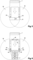
- the peripheral detection zone 8 may comprise at least four overlapping portions 26, including a front overlapping portion 26a located in front of the vehicle 1, a front overlapping portion 26b located in front of the vehicle 1, a front overlapping portion 26c located in front of the vehicle 1, a front overlapping portion 26d located in front of the vehicle 1, a front overlapping portion 26e located in front of the vehicle 1, a front overlapping portion 26f ...g located in front of the vehicle 1, a front overlapping portion 26h located in front of the vehicle 1, a front overlapping portion 26h located in front of the vehicle 1, a front overlapping portion 26h located in front of the vehicle 1 rear covering located behind vehicle 1, and two lateral covering portions 26c located on each side of vehicle 1.
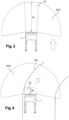
- vehicle 1 is moving in a straight line. Its speed is significantly higher than when vehicle 1 is moving around a bend ( Figure 4 ) or performs a reverse gear ( Figure 5 ) or a docking maneuver ( figures 6 And 7 ) or a half turn ( figure 8 ).
- the speed of vehicle 1 is, for example, around 25 km/h in a straight line, around 7 km/h when turning, around 5 km/h when reversing and inside buildings, and around 1 km/h when making a U-turn.
- the straight-line surveillance zone 10 extends lengthwise in front of the vehicle 1 over a distance d1 of at least 7 m for a vehicle speed of around 25 km/h, this distance being minimal in dry weather and increased in wet weather.
- the surveillance zone 10 may extend over a distance d2 of at least 1 m for a vehicle speed of around 7 km/h.
- the surveillance zone 10 may extend over a distance d3 of at least 60 cm for a vehicle speed of around 5 km/h.
- the width of surveillance zone 10 corresponds approximately, for forward and reverse travel excluding docking maneuvers, to the width of vehicle 1.
- the monitoring zone 10 may have a substantially rectangular, slightly trapezoidal shape to allow crossings with a safety distance as seen on the Figures 3 and 4 .
- the monitoring zone 10 may have a substantially triangular shape, depending on the part of the vehicle 1 which is furthest from the axis of rotation of the U-turn.
- One of the sides of the triangle extending substantially perpendicular to one of the sides of the vehicle 1, may extend over a distance d5 of the order of 20 cm.
- Another side of the triangle extends substantially over the entire length of the side of the vehicle 1 on the side of which the U-turn is made.
- the surveillance zone 10 can extend over a distance d4 of the order of 10 cm.
- the detection of the fact that the vehicle is performing a docking maneuver and the calculation of the appropriate corresponding monitoring zone 10 are, according to another example, carried out by detection by the collection means and the processing unit 16 that the speed of the vehicle is within a certain predetermined speed range.
- This predetermined speed range may be between 0 and 3 km/h in the direction of the docking maneuver, here in reverse, and preferably between 0.5 and 2 km/h.
- the vehicle may include a load sensor making it possible to send to the processing unit 16 the information according to which the vehicle is loaded or not loaded.
- the processing unit 16 knows that the vehicle is performing a simple movement, here reversing, and not a docking maneuver even if the speed of the vehicle is within the predetermined speed range.
- the detection of the fact that the vehicle is performing a docking maneuver and the calculation of the appropriate corresponding monitoring zone 10 are, according to another example, carried out by detection by the collection means and the processing unit 16 that the speed of the vehicle corresponds for a determined duration to a constant speed predefined as being the docking speed.
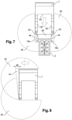
- the monitoring zone 10 comprises, during a docking maneuver, a predetermined inhibited zone 28, exempt from monitoring by the remote obstacle detection means, and located between the vehicle 1 and the load to be docked, in this case an anode assembly 2.
- the vehicle 1 can dock the load without untimely stopping due to detection of the load as an obstacle by the remote obstacle detection means.
- the vehicle further comprises means for detecting obstacles by contact, for example a bumper 18 shown schematically in the figures 2 And 6 , in particular in the form of a plate, connected to the vehicle 1 by one or more return members 20.
- a bumper 18 shown schematically in the figures 2 And 6 in particular in the form of a plate, connected to the vehicle 1 by one or more return members 20.
- the obstacle detection means by contact are arranged on a portion of the vehicle intended to face the load to be docked during a docking maneuver. According to the example of figures 1 to 8 , the means of obstacle detection by contact are therefore visible from the rear of the vehicle.
- the braking means are activated to brake and stop the vehicle.
- the contact obstacle detection means are arranged to detect an obstacle which would be located in the inhibited zone 28.
- the vehicle 1 comprises a U-shaped chassis comprising two substantially parallel lateral portions 30 between which the docking means extend and connected by a central portion 32.
- the obstacle detection means by contact comprise a first detection member, such as a bumper 18, arranged inside the U and connected to the central portion 32, as can be seen in the Figure 2 .
- an internal bumper 18 also has a safety benefit for starting in reverse of a vehicle 1 which had remained stopped: a person could have entered the loading zone during the stop, that is to say inside the U formed by the central portion 32 and the lateral portions 30.
- the obstacle detection means by contact may also comprise a second detection member and a third detection member, such as bumpers 18, arranged at the end of the lateral portions 30.
- the vehicle 1 may for this purpose comprise means, such as a stop (not shown), to prevent contact between the load and the first detection member.
- the surveillance zone 10 can be subdivided into two separate surveillance sub-zones 10a, 10b, each extending from the end of the lateral portions 30, in the direction of movement of the vehicle 1.
- the two surveillance sub-zones 10a, 10b are distant from each other, they do not overlap.
- the non-contact detection units 22 have their monitoring zone 10 modified to continue monitoring the sides of the load to be docked, in this case an anode assembly according to the example of the Figure 6 .
- separate surveillance sub-zones 10a, 10b may extend, as seen on the Figure 7 , from the vehicle to the sides of the load to be docked before the load to be docked enters the U-shaped chassis so as to prevent pedestrians or machinery from entering the inhibited zone 28 during the docking maneuver.
- the distances d4 over which the monitoring sub-zones 10a, 10b extend may, for example, change during the docking maneuver, decreasing as the docking maneuver progresses. Such a change may be determined, for example, as a function of the time progress of the docking maneuver or by detecting that the load to be docked has entered the U-shaped chassis.
- the detection units 22 can be arranged on the two corners, front left and front right, of the central portion 32 and at the two ends of the lateral portions 30.
- the vehicle 1 may advantageously comprise shape recognition means, intended to recognize the shape of the load to be docked during a docking maneuver.
- These shape recognition means may comprise one or more lasers arranged to scan a loading area of the vehicle, i.e. an area traveled by the vehicle during a docking maneuver.
- a loading area of the vehicle i.e. an area traveled by the vehicle during a docking maneuver.
- the loading area corresponds to a rear area of the vehicle, because the docking maneuver is carried out in reverse.
- the shape recognition means may be combined with the remote obstacle detection means.
- the laser(s) forming the shape recognition means may advantageously be combined with the laser(s) forming the remote detection units 22.
- the shape recognition means may alternatively be completely independent or even form part, where appropriate, of the automatic guidance means described in more detail below.
- the remote obstacle detection means and the contact obstacle detection means are, for example, arranged at most 350 mm from the ground, in particular at most 300 mm from the ground, and preferably at most 200 mm from the ground.
- the remote obstacle detection means and the contact obstacle detection means may in particular be arranged at a height corresponding to the height of an upper surface of the wheels 14 of the vehicle 1.
- the vehicle 1 advantageously comprises automatic guidance means for moving autonomously in an electrolysis plant.
- These automatic guidance means may include, for example, a SLAM (Simultaneous Localisation And Mapping) system.
- the guidance means use, for example, laser rangefinders, cameras, ultrasonic sensors, and/or capacitive sensors, and a storage unit capable of storing a digitized map of the electrolysis plant and/or a map of the routes in the form of a database.
- the remote obstacle detection means and the contact obstacle detection means are advantageously independent of the automatic guidance means.
- independent is meant that the obstacle detection means (remote and contact) can operate in the absence of operation of the automatic guidance means, and do not receive no information from the automatic guidance means to define the surveillance zones and the safety actions to be implemented.
- the automatic guidance means ensure safe operation of the vehicle, but this safe operation depends on complex processes governing the vehicle's movements.
- the obstacle detection means are specifically dedicated to safety and are added to the automatic guidance means to ensure safer operation of the vehicle.
- the independence between the obstacle detection means and the automatic guidance means ensures perfectly safe operation of the vehicle, in particular because the obstacle detection means do not depend on the correct operation of the automatic guidance means.
- the present invention also relates to an electrolysis plant, in particular an aluminum smelter, comprising at least one handling vehicle 1 as previously described.
Landscapes
- Engineering & Computer Science (AREA)
- Chemical & Material Sciences (AREA)
- Transportation (AREA)
- Mechanical Engineering (AREA)
- Metallurgy (AREA)
- General Engineering & Computer Science (AREA)
- Structural Engineering (AREA)
- Organic Chemistry (AREA)
- Chemical Kinetics & Catalysis (AREA)
- Electrochemistry (AREA)
- Materials Engineering (AREA)
- Life Sciences & Earth Sciences (AREA)
- Geology (AREA)
- Aviation & Aerospace Engineering (AREA)
- Radar, Positioning & Navigation (AREA)
- Remote Sensing (AREA)
- Physics & Mathematics (AREA)
- General Physics & Mathematics (AREA)
- Automation & Control Theory (AREA)
- Civil Engineering (AREA)
- Combustion & Propulsion (AREA)
- Traffic Control Systems (AREA)
- Control Of Position, Course, Altitude, Or Attitude Of Moving Bodies (AREA)
Claims (17)
- Handhabungsfahrzeug (1), umfassend Andockmittel zum Andocken an eine zu bewegende Last, insbesondere eine Anodenanordnung (2) oder einen Gussbehälter einer Elektrolyseanlage, wobei das Fahrzeug (1) umfasst:- Mittel zur Ferndetektion eines Hindernisses, die zum Absuchen einer Detektionszone (8) geeignet sind, die an das Fahrzeug (1) angrenzt, wobei die Detektionszone (8) der maximalen Zone entspricht, die von den Mitteln zur Ferndetektion eines Hindernisses abgedeckt werden kann, wobei die Mittel zur Ferndetektion eines Hindernisses eine Vielzahl von Detektionseinheiten (22) umfassen, die jeweils dazu bestimmt sind, eine lokale Detektionszone (24) abzusuchen, die einem festen Teil der Detektionszone (8) entspricht, wobei die Detektionseinheiten (22) zueinander so angeordnet sind, dass ihre lokalen Detektionszonen (24) zusammen die Detektionszone (8) bilden, die sich 360° um das Fahrzeug (1) herum erstreckt,- Mittel zur Sammlung kinematischer Daten, die dazu bestimmt sind, ein oder mehrere Daten betreffend die Kinematik des Fahrzeugs (1) zu sammeln, wobei das Fahrzeug (1) weiter Mittel zur Detektion eines Hindernisses durch Kontakt umfasst, die auf einem Abschnitt des Fahrzeugs (1) angeordnet sind, der dazu bestimmt ist, der anzudockenden Last bei einem Andockmanöver gegenüberzutreten, und dadurch gekennzeichnet, dass das Fahrzeug eine Verarbeitungseinheit (16) umfasst, die dazu bestimmt ist, innerhalb der Detektionszone (8) eine Überwachungszone (10) zu definieren, die durch die Mittel zur Ferndetektion eines Hindernisses zu überwachen ist, wobei die Überwachungszone (10) nicht fest ist, und einem Teil der Detektionszone (8) entspricht, wobei die Form der Überwachungszone (10) durch die Verarbeitungseinheit (16) in Abhängigkeit von dem oder den kinematischen Daten berechnet wird, die durch die Mittel zur Sammlung bereitgestellt werden, und Bremsmittel, die dazu bestimmt sind, das Fahrzeug (1) zu bremsen und/oder anzuhalten, sobald ein Hindernis in der Überwachungszone detektiert wird oder durch die Mittel zur Detektion eines Hindernisses durch Kontakt angestoßen wird.
- Fahrzeug (1) nach Anspruch 1, dadurch gekennzeichnet, dass jede lokale Detektionszone (24) mindestens einen Überschneidungsabschnitt (26) mit einer angrenzenden lokalen Detektionszone (24) aufweist.
- Fahrzeug nach Anspruch 2, dadurch gekennzeichnet, dass die umlaufende Detektionszone (8) mindestens vier Überschneidungsabschnitte (26) umfasst, davon einen vorderen Überschneidungsabschnitt (26a), der sich vor dem Fahrzeug (1) befindet, einen hinteren Überschneidungsabschnitt (26b), der sich hinter dem Fahrzeug (1) befindet, und zwei seitliche Überschneidungsabschnitte (26c), die sich auf jeder Seite des Fahrzeugs (1) befinden.
- Fahrzeug nach einem der Ansprüche 1 bis 3, dadurch gekennzeichnet, dass die Verarbeitungseinheit (16) ausgehend von den kinematischen Daten bestimmt, dass das Fahrzeug (1) ein Andockmanöver durchführt, und eine angemessene Überwachungszone (10) bei einem Andockmanöver definiert.
- Fahrzeug nach Anspruch 4, dadurch gekennzeichnet, dass die kinematischen Daten, die es der Verarbeitungseinheit ermöglichen, zu bestimmen, dass das Fahrzeug ein Andockmanöver durchführt, und eine angemessene Überwachungszone (10) bei einem Andockmanöver zu definieren, ein vorbestimmter Geschwindigkeitsbereich in der Richtung des Andockmanövers sind.
- Fahrzeug nach Anspruch 5, dadurch gekennzeichnet, dass der vorbestimmte Geschwindigkeitsbereich zwischen 0 und 3 km/h, und vorzugsweise zwischen 0,5 und 2 km/h umfasst ist.
- Fahrzeug (1) nach einem der Ansprüche 1 bis 6, dadurch gekennzeichnet, dass die kinematischen Daten, die es der Verarbeitungseinheit (16) ermöglichen, zu bestimmen, dass das Fahrzeug ein Andockmanöver durchführt, und eine angemessene Überwachungszone (10) bei einem Andockmanöver zu definieren, die Aufrechterhaltung einer vordefinierten konstanten Geschwindigkeit während einer bestimmten Dauer umfassen.
- Fahrzeug (1) nach Anspruch 7, dadurch gekennzeichnet, dass die vordefinierte konstante Geschwindigkeit zwischen 0,5 und 2,5 km/h, vorzugsweise zwischen 1 und 2 km/h umfasst ist, besonders bevorzugt in etwa 1,8 km/h beträgt.
- Fahrzeug nach einem der Ansprüche 7 bis 8, dadurch gekennzeichnet, dass die bestimmte Dauer zwischen 0,1 und 2 Sekunden umfasst ist, und vorzugsweise kürzer ist als 1 Sekunde ist.
- Fahrzeug (1) nach einem der Ansprüche 1 bis 9, dadurch gekennzeichnet, dass die Überwachungszone (10) bei einem Andockmanöver eine vorbestimmte Sperrzone (28) umfasst, die frei von einer Überwachung durch die Mittel zur Ferndetektion eines Hindernisses ist, wobei sich die Sperrzone (28) zwischen dem Fahrzeug (1) und der anzudockenden Last befindet, und die Mittel zur Detektion eines Hindernisses durch Kontakt angeordnet sind, um ein Hindernis in der Sperrzone (28) zu detektieren.
- Fahrzeug (1) nach Anspruch 10, dadurch gekennzeichnet, dass die Überwachungszone (10) mindestens zwei Überwachungsunterzonen (10a, 10b) beinhaltet, die sich entlang der Sperrzone (28) erstrecken.
- Fahrzeug (1) nach einem der Ansprüche 1 bis 11, dadurch gekennzeichnet, dass das Fahrzeug (1) ein Fahrgestell in U-Form umfasst, das zwei im Wesentlichen parallele seitliche Abschnitte (30) umfasst, zwischen denen sich die Andockmittel erstrecken und die durch einen mittleren Abschnitt (32) verbunden sind, und die Mittel zur Detektion eines Hindernisses durch Kontakt ein erstes Detektionsorgan umfassen, das innerhalb des U auf dem mittleren Abschnitt (32) angeordnet ist.
- Fahrzeug (1) nach Anspruch 12, dadurch gekennzeichnet, dass die Mittel zur Detektion eines Hindernisses durch Kontakt ein zweites Detektionsorgan und ein drittes Detektionsorgan umfassen, die am Ende der seitlichen Abschnitte (30) angeordnet sind.
- Fahrzeug (1) nach Anspruch 12 oder 13, dadurch gekennzeichnet, dass die Überwachungszone (10) während eines Andockmanövers zwei Überwachungsunterzonen (10a, 10b) umfasst, die getrennt sind und sich jeweils von einem Ende der seitlichen Abschnitte (30) in einer Richtung erstrecken, die im Wesentlichen parallel zur Bewegungsrichtung des Fahrzeugs (1) verläuft.
- Fahrzeug (1) nach Anspruch 14, dadurch gekennzeichnet, dass sich die getrennten Überwachungsunterzonen (10a, 10b) von dem Fahrzeug bis auf die Seiten der anzudockenden Last erstrecken, bevor die anzudockende Last in das Fahrgestell in U-Form eindringt.
- Fahrzeug (1) nach einem der Ansprüche 1 bis 15, dadurch gekennzeichnet, dass das Fahrzeug Mittel zur automatischen Führung umfasst, um sich auf autonome Weise in einer Elektrolyseanlage zu bewegen, und die Mittel zur Ferndetektion eines Hindernisses und die Mittel zur Detektion eines Hindernisses durch Kontakt unabhängig von den Mitteln zur automatischen Führung sind.
- Elektrolyseanlage, insbesondere Aluminiumhütte, umfassend ein Handhabungsfahrzeug (1) nach einem der Ansprüche 1 bis 16.
Applications Claiming Priority (2)
| Application Number | Priority Date | Filing Date | Title |
|---|---|---|---|
| FR1302482A FR3012387B1 (fr) | 2013-10-25 | 2013-10-25 | Vehicule de manutention et usine d'electrolyse comprenant ce vehicule |
| PCT/IB2014/002222 WO2015059556A1 (fr) | 2013-10-25 | 2014-10-23 | Véhicule de manutention et usine d'électrolyse comprenant ce véhicule |
Publications (4)
| Publication Number | Publication Date |
|---|---|
| EP3060456A1 EP3060456A1 (de) | 2016-08-31 |
| EP3060456A4 EP3060456A4 (de) | 2017-09-13 |
| EP3060456B1 EP3060456B1 (de) | 2019-12-18 |
| EP3060456B2 true EP3060456B2 (de) | 2025-07-09 |
Family
ID=50064670
Family Applications (1)
| Application Number | Title | Priority Date | Filing Date |
|---|---|---|---|
| EP14855653.3A Active EP3060456B2 (de) | 2013-10-25 | 2014-10-23 | Manöverfahrzeug und elektrolyseanlage mit diesem fahrzeug |
Country Status (7)
| Country | Link |
|---|---|
| EP (1) | EP3060456B2 (de) |
| CN (1) | CN105658507B (de) |
| AU (1) | AU2014338685B2 (de) |
| CA (1) | CA2926924C (de) |
| FR (1) | FR3012387B1 (de) |
| RU (1) | RU2667997C2 (de) |
| WO (1) | WO2015059556A1 (de) |
Families Citing this family (7)
| Publication number | Priority date | Publication date | Assignee | Title |
|---|---|---|---|---|
| EP3269679B2 (de) | 2016-07-14 | 2024-12-04 | Toyota Material Handling Manufacturing Sweden AB | Flurförderer |
| EP3908498B1 (de) | 2019-01-11 | 2023-09-06 | Dürr Systems AG | Fördervorrichtung, bearbeitungsanlage, verfahren zum fördern und/oder bearbeiten von gegenständen |
| ES2934144T3 (es) | 2019-03-20 | 2023-02-17 | Asti Mobile Robotics S A U | Vehículo autónomo omnidireccional |
| AU2020202391B2 (en) * | 2019-04-05 | 2025-08-21 | The Raymond Corporation | Pallet detection systems and methods for a material handling device |
| CN112776917B (zh) * | 2021-02-08 | 2024-12-24 | 深圳优艾智合机器人科技有限公司 | 用于自动导引车的驱动装置、自动导引车及机器人 |
| CN112896364B (zh) * | 2021-02-08 | 2024-12-20 | 西安优艾智合机器人科技有限公司 | 用于自动导引车的驱动装置、自动导引车及机器人 |
| DE102021130254A1 (de) | 2021-11-19 | 2023-05-25 | Jungheinrich Aktiengesellschaft | Verfahren zum handhaben von störungen in flurförderzeugen |
Citations (8)
| Publication number | Priority date | Publication date | Assignee | Title |
|---|---|---|---|---|
| DE4218041A1 (de) † | 1992-06-01 | 1993-12-02 | Microsonic Ges Fuer Mikroelekt | Ultraschallsensor mit Funktionsüberwachung |
| DE202005004466U1 (de) † | 2005-03-19 | 2005-09-01 | Sick Ag | Vorrichtung zur Erfassung von Objekten |
| DE102004047209B4 (de) † | 2004-09-27 | 2009-04-23 | Daimler Ag | Verfahren und Vorrichtung zur Sicherheitsüberwachung für Transportfahrzeuge |
| EP2302416A1 (de) † | 2009-09-28 | 2011-03-30 | Sick Ag | Sicherheitsscanner |
| EP2386876A1 (de) † | 2010-05-04 | 2011-11-16 | Sick AG | Entfernungsmessender optoelektronischer Sicherheitssensor und Verfahren zur Überwachung eines Überwachungsbereichs |
| EP2428862A1 (de) † | 2010-09-13 | 2012-03-14 | Sick Ag | Vorrichtung und Verfahren zur Sicherheitssteuerung eines Fahrzeuges |
| DE102011085019A1 (de) † | 2010-10-22 | 2012-04-26 | Kuka Laboratories Gmbh | Autonomes Fahrzeug, zuhöriger Anhänger und autonomes Transportsystem |
| EP2515143A1 (de) † | 2011-04-18 | 2012-10-24 | Sick Ag | Verfahren zur sicheren Erfassung und Positionsbestimmung von Objekten und Sicherheitsvorrichtung |
Family Cites Families (16)
| Publication number | Priority date | Publication date | Assignee | Title |
|---|---|---|---|---|
| DE3730105A1 (de) * | 1987-09-08 | 1989-03-16 | Pietzsch Ibp Gmbh | Verfahren und einrichtung zum sichern eines im raum beweglichen fahrzeugs oder geraets |
| DE4234375C2 (de) * | 1992-10-12 | 1995-10-12 | Noell Gmbh | Vorrichtung zur Personen- und Kollisionssicherung von fahrerlosen Gabelhubfahrzeugen |
| DE19613386A1 (de) * | 1996-04-03 | 1997-10-09 | Fiat Om Carrelli Elevatori | Flurförderzeug, das wahlweise manuell oder automatisch betreibbar ausgebildet ist |
| DE19749900A1 (de) * | 1997-11-12 | 1999-06-02 | Siemag Transplan Gmbh | Fahrerloses, z. B. frei navigierendes Transportfahrzeug zum Handhaben von Lasten |
| DE29724786U1 (de) * | 1997-11-12 | 2004-04-01 | Siemag Gmbh | Fahrerloses, z.B. frei navigierendes Transportfahrzeug zum Handhaben von Lasten |
| KR20040101225A (ko) * | 2002-02-12 | 2004-12-02 | 타이네캣 테크놀로지스 피티와이 리미티드 | 운송 트롤리 |
| JP4623631B2 (ja) * | 2004-09-10 | 2011-02-02 | 日本輸送機株式会社 | オーダピッキングトラック |
| DE102004058472B4 (de) * | 2004-11-24 | 2006-12-14 | Pilz Gmbh & Co. Kg | Sicherheitseinrichtung und Verfahren zum Bestimmen eines Nachlaufweges bei einer Maschine |
| CN2795178Y (zh) * | 2005-05-24 | 2006-07-12 | 机科发展科技股份有限公司 | 激光导引自动运输车 |
| MX2009002803A (es) * | 2006-09-14 | 2009-05-12 | Crown Equip Corp | Sistemas y metodos para controlar de manera remota un vehiculo de manejo de materiales. |
| KR101653968B1 (ko) * | 2008-12-04 | 2016-09-05 | 크라운 이큅먼트 코포레이션 | 물류 취급 차량용 다중 구역 감지 |
| US8731777B2 (en) * | 2009-08-18 | 2014-05-20 | Crown Equipment Corporation | Object tracking and steer maneuvers for materials handling vehicles |
| AT509305B1 (de) * | 2009-12-15 | 2012-03-15 | Amx Automation Technologies Gmbh | Fahrerlose transporteinrichtung |
| US20110298579A1 (en) * | 2010-06-08 | 2011-12-08 | Cedes Safety & Automation Ag | Dynamically adaptable safety zones |
| RU2452683C2 (ru) * | 2010-08-13 | 2012-06-10 | Общество с ограниченной ответственностью "Научно-производственное предприятие "Резонанс" | Система безопасности строительных машин (варианты) |
| DE102011109532A1 (de) * | 2011-08-05 | 2013-02-07 | Sew-Eurodrive Gmbh & Co. Kg | Anlage und Verfahren zum Betreiben einer Anlage |
-
2013
- 2013-10-25 FR FR1302482A patent/FR3012387B1/fr active Active
-
2014
- 2014-10-23 AU AU2014338685A patent/AU2014338685B2/en active Active
- 2014-10-23 EP EP14855653.3A patent/EP3060456B2/de active Active
- 2014-10-23 CA CA2926924A patent/CA2926924C/fr active Active
- 2014-10-23 RU RU2016119961A patent/RU2667997C2/ru active
- 2014-10-23 CN CN201480058357.3A patent/CN105658507B/zh active Active
- 2014-10-23 WO PCT/IB2014/002222 patent/WO2015059556A1/fr not_active Ceased
Patent Citations (8)
| Publication number | Priority date | Publication date | Assignee | Title |
|---|---|---|---|---|
| DE4218041A1 (de) † | 1992-06-01 | 1993-12-02 | Microsonic Ges Fuer Mikroelekt | Ultraschallsensor mit Funktionsüberwachung |
| DE102004047209B4 (de) † | 2004-09-27 | 2009-04-23 | Daimler Ag | Verfahren und Vorrichtung zur Sicherheitsüberwachung für Transportfahrzeuge |
| DE202005004466U1 (de) † | 2005-03-19 | 2005-09-01 | Sick Ag | Vorrichtung zur Erfassung von Objekten |
| EP2302416A1 (de) † | 2009-09-28 | 2011-03-30 | Sick Ag | Sicherheitsscanner |
| EP2386876A1 (de) † | 2010-05-04 | 2011-11-16 | Sick AG | Entfernungsmessender optoelektronischer Sicherheitssensor und Verfahren zur Überwachung eines Überwachungsbereichs |
| EP2428862A1 (de) † | 2010-09-13 | 2012-03-14 | Sick Ag | Vorrichtung und Verfahren zur Sicherheitssteuerung eines Fahrzeuges |
| DE102011085019A1 (de) † | 2010-10-22 | 2012-04-26 | Kuka Laboratories Gmbh | Autonomes Fahrzeug, zuhöriger Anhänger und autonomes Transportsystem |
| EP2515143A1 (de) † | 2011-04-18 | 2012-10-24 | Sick Ag | Verfahren zur sicheren Erfassung und Positionsbestimmung von Objekten und Sicherheitsvorrichtung |
Also Published As
| Publication number | Publication date |
|---|---|
| CA2926924A1 (fr) | 2015-04-30 |
| RU2667997C2 (ru) | 2018-09-25 |
| FR3012387B1 (fr) | 2015-10-30 |
| AU2014338685B2 (en) | 2017-06-01 |
| RU2016119961A (ru) | 2017-11-30 |
| EP3060456A4 (de) | 2017-09-13 |
| RU2016119961A3 (de) | 2018-07-24 |
| CN105658507B (zh) | 2018-09-28 |
| FR3012387A1 (fr) | 2015-05-01 |
| CA2926924C (fr) | 2022-04-26 |
| NZ718752A (en) | 2020-09-25 |
| AU2014338685A1 (en) | 2016-04-07 |
| EP3060456B1 (de) | 2019-12-18 |
| WO2015059556A1 (fr) | 2015-04-30 |
| EP3060456A1 (de) | 2016-08-31 |
| CN105658507A (zh) | 2016-06-08 |
Similar Documents
| Publication | Publication Date | Title |
|---|---|---|
| EP3060456B2 (de) | Manöverfahrzeug und elektrolyseanlage mit diesem fahrzeug | |
| EP3152097B1 (de) | Parkhilfesystem vorrichtung und fahrzeug mit einer derartigen vorrichtung | |
| EP3371035B1 (de) | Vorrichtung zur unterstützung von manövern zum parken entlang einer plattform | |
| FR3036349A1 (fr) | Convoyeurs mobiles destines au deplacement d'un vehicule a 4 roues. | |
| FR2969098A1 (fr) | Procede et dispositif d'assistance du conducteur d'un vehicule | |
| FR3073767A1 (fr) | Systeme de transport automatique de vehicule avec un robot de transport | |
| FR3048406B1 (fr) | Robot autonome avec guidage en mode poussee | |
| CA3125741A1 (fr) | Equipement de manutention autoguide comportant un moyen de detection | |
| EP1201536B1 (de) | Vorichtung zum Lagern von Booten mit automatischem an Land und ins Wasser setzen | |
| EP3061048B1 (de) | System zur verwaltung von logistikdatenflüssen in einem elektrolysesystem, aluminiumschmelzer mit diesem system, fahrzeug zur verwendung des systems und verfahren zum integrieren dieses systems in ein bereits bestehendes elektrolysesystem | |
| EP1694525B1 (de) | Vorrichtung zur führung und elektrischen energieversorgung eines fahrzeugs durch eine rinne im boden | |
| EP1043262A1 (de) | Verfahren zum Laden eines Containers auf die Plattform eines Transportmittels und Einrichtung zum Lagern und Fördern von Containern | |
| FR3063274A1 (fr) | Vehicule autonome a roues jumelles, destine au transport de colis ou de materiels, permettant de franchir de petits obstacles | |
| FR3042766B1 (fr) | Procede et dispositif pour determiner s'il faut executer une action de securite pour reduire le risque de collision d'un vehicule avec un objet | |
| KR102420506B1 (ko) | 크레인 충돌방지를 위한 지능형 비전 센서 | |
| WO2017153895A1 (fr) | Robot motorisé autonome pour le transport de charges | |
| FR3098836A1 (fr) | Dispositif transporteur de véhicules à quatre roues | |
| FI127421B (fi) | Menetelmä kuormaimen ohjaamiseksi ja kuormaimenohjauslaitteisto | |
| CN221251061U (zh) | 一种基于滑板智能底盘的自动驾驶车辆 | |
| JP2023108288A (ja) | 管理システム | |
| FR3033485A1 (fr) | Appareil autonome de netttoyage de sol, a detection d'obstacles amelioree. | |
| FI127539B (fi) | Menetelmä kuormaimen kuormainkouran ja kaatopään ohjaamiseksi | |
| FR2937744A1 (fr) | Systeme d'aide a la manoeuvre d'un navire | |
| NZ718752B2 (en) | Handling vehicle and electrolysis plant comprising said vehicle | |
| FR2926051A1 (fr) | Dispositif modulaire de pilotage pour un chariot automoteur |
Legal Events
| Date | Code | Title | Description |
|---|---|---|---|
| PUAI | Public reference made under article 153(3) epc to a published international application that has entered the european phase |
Free format text: ORIGINAL CODE: 0009012 |
|
| 17P | Request for examination filed |
Effective date: 20160513 |
|
| AK | Designated contracting states |
Kind code of ref document: A1 Designated state(s): AL AT BE BG CH CY CZ DE DK EE ES FI FR GB GR HR HU IE IS IT LI LT LU LV MC MK MT NL NO PL PT RO RS SE SI SK SM TR |
|
| AX | Request for extension of the european patent |
Extension state: BA ME |
|
| RAP1 | Party data changed (applicant data changed or rights of an application transferred) |
Owner name: RIO TINTO ALCAN INTERNATIONAL LIMITED |
|
| DAX | Request for extension of the european patent (deleted) | ||
| REG | Reference to a national code |
Ref country code: DE Ref legal event code: R079 Ref document number: 602014058735 Country of ref document: DE Free format text: PREVIOUS MAIN CLASS: B62D0041000000 Ipc: B60P0001000000 |
|
| A4 | Supplementary search report drawn up and despatched |
Effective date: 20170814 |
|
| RIC1 | Information provided on ipc code assigned before grant |
Ipc: B66F 9/06 20060101ALI20170808BHEP Ipc: B60P 1/00 20060101AFI20170808BHEP |
|
| GRAP | Despatch of communication of intention to grant a patent |
Free format text: ORIGINAL CODE: EPIDOSNIGR1 |
|
| STAA | Information on the status of an ep patent application or granted ep patent |
Free format text: STATUS: GRANT OF PATENT IS INTENDED |
|
| INTG | Intention to grant announced |
Effective date: 20190711 |
|
| GRAS | Grant fee paid |
Free format text: ORIGINAL CODE: EPIDOSNIGR3 |
|
| GRAA | (expected) grant |
Free format text: ORIGINAL CODE: 0009210 |
|
| STAA | Information on the status of an ep patent application or granted ep patent |
Free format text: STATUS: THE PATENT HAS BEEN GRANTED |
|
| AK | Designated contracting states |
Kind code of ref document: B1 Designated state(s): AL AT BE BG CH CY CZ DE DK EE ES FI FR GB GR HR HU IE IS IT LI LT LU LV MC MK MT NL NO PL PT RO RS SE SI SK SM TR |
|
| REG | Reference to a national code |
Ref country code: CH Ref legal event code: EP |
|
| REG | Reference to a national code |
Ref country code: IE Ref legal event code: FG4D Free format text: LANGUAGE OF EP DOCUMENT: FRENCH |
|
| REG | Reference to a national code |
Ref country code: DE Ref legal event code: R096 Ref document number: 602014058735 Country of ref document: DE |
|
| REG | Reference to a national code |
Ref country code: AT Ref legal event code: REF Ref document number: 1214228 Country of ref document: AT Kind code of ref document: T Effective date: 20200115 |
|
| REG | Reference to a national code |
Ref country code: NL Ref legal event code: MP Effective date: 20191218 |
|
| PG25 | Lapsed in a contracting state [announced via postgrant information from national office to epo] |
Ref country code: LT Free format text: LAPSE BECAUSE OF FAILURE TO SUBMIT A TRANSLATION OF THE DESCRIPTION OR TO PAY THE FEE WITHIN THE PRESCRIBED TIME-LIMIT Effective date: 20191218 Ref country code: SE Free format text: LAPSE BECAUSE OF FAILURE TO SUBMIT A TRANSLATION OF THE DESCRIPTION OR TO PAY THE FEE WITHIN THE PRESCRIBED TIME-LIMIT Effective date: 20191218 Ref country code: LV Free format text: LAPSE BECAUSE OF FAILURE TO SUBMIT A TRANSLATION OF THE DESCRIPTION OR TO PAY THE FEE WITHIN THE PRESCRIBED TIME-LIMIT Effective date: 20191218 Ref country code: FI Free format text: LAPSE BECAUSE OF FAILURE TO SUBMIT A TRANSLATION OF THE DESCRIPTION OR TO PAY THE FEE WITHIN THE PRESCRIBED TIME-LIMIT Effective date: 20191218 Ref country code: BG Free format text: LAPSE BECAUSE OF FAILURE TO SUBMIT A TRANSLATION OF THE DESCRIPTION OR TO PAY THE FEE WITHIN THE PRESCRIBED TIME-LIMIT Effective date: 20200318 Ref country code: GR Free format text: LAPSE BECAUSE OF FAILURE TO SUBMIT A TRANSLATION OF THE DESCRIPTION OR TO PAY THE FEE WITHIN THE PRESCRIBED TIME-LIMIT Effective date: 20200319 |
|
| REG | Reference to a national code |
Ref country code: LT Ref legal event code: MG4D Ref country code: NO Ref legal event code: T2 Effective date: 20191218 |
|
| PG25 | Lapsed in a contracting state [announced via postgrant information from national office to epo] |
Ref country code: HR Free format text: LAPSE BECAUSE OF FAILURE TO SUBMIT A TRANSLATION OF THE DESCRIPTION OR TO PAY THE FEE WITHIN THE PRESCRIBED TIME-LIMIT Effective date: 20191218 Ref country code: RS Free format text: LAPSE BECAUSE OF FAILURE TO SUBMIT A TRANSLATION OF THE DESCRIPTION OR TO PAY THE FEE WITHIN THE PRESCRIBED TIME-LIMIT Effective date: 20191218 |
|
| PG25 | Lapsed in a contracting state [announced via postgrant information from national office to epo] |
Ref country code: AL Free format text: LAPSE BECAUSE OF FAILURE TO SUBMIT A TRANSLATION OF THE DESCRIPTION OR TO PAY THE FEE WITHIN THE PRESCRIBED TIME-LIMIT Effective date: 20191218 |
|
| PG25 | Lapsed in a contracting state [announced via postgrant information from national office to epo] |
Ref country code: RO Free format text: LAPSE BECAUSE OF FAILURE TO SUBMIT A TRANSLATION OF THE DESCRIPTION OR TO PAY THE FEE WITHIN THE PRESCRIBED TIME-LIMIT Effective date: 20191218 Ref country code: PT Free format text: LAPSE BECAUSE OF FAILURE TO SUBMIT A TRANSLATION OF THE DESCRIPTION OR TO PAY THE FEE WITHIN THE PRESCRIBED TIME-LIMIT Effective date: 20200513 Ref country code: NL Free format text: LAPSE BECAUSE OF FAILURE TO SUBMIT A TRANSLATION OF THE DESCRIPTION OR TO PAY THE FEE WITHIN THE PRESCRIBED TIME-LIMIT Effective date: 20191218 Ref country code: CZ Free format text: LAPSE BECAUSE OF FAILURE TO SUBMIT A TRANSLATION OF THE DESCRIPTION OR TO PAY THE FEE WITHIN THE PRESCRIBED TIME-LIMIT Effective date: 20191218 Ref country code: EE Free format text: LAPSE BECAUSE OF FAILURE TO SUBMIT A TRANSLATION OF THE DESCRIPTION OR TO PAY THE FEE WITHIN THE PRESCRIBED TIME-LIMIT Effective date: 20191218 |
|
| REG | Reference to a national code |
Ref country code: DE Ref legal event code: R026 Ref document number: 602014058735 Country of ref document: DE |
|
| PLBI | Opposition filed |
Free format text: ORIGINAL CODE: 0009260 |
|
| PG25 | Lapsed in a contracting state [announced via postgrant information from national office to epo] |
Ref country code: SM Free format text: LAPSE BECAUSE OF FAILURE TO SUBMIT A TRANSLATION OF THE DESCRIPTION OR TO PAY THE FEE WITHIN THE PRESCRIBED TIME-LIMIT Effective date: 20191218 Ref country code: SK Free format text: LAPSE BECAUSE OF FAILURE TO SUBMIT A TRANSLATION OF THE DESCRIPTION OR TO PAY THE FEE WITHIN THE PRESCRIBED TIME-LIMIT Effective date: 20191218 |
|
| 26 | Opposition filed |
Opponent name: SEW-EURODRIVE GMBH & CO. KG Effective date: 20200814 |
|
| PLAX | Notice of opposition and request to file observation + time limit sent |
Free format text: ORIGINAL CODE: EPIDOSNOBS2 |
|
| REG | Reference to a national code |
Ref country code: AT Ref legal event code: MK05 Ref document number: 1214228 Country of ref document: AT Kind code of ref document: T Effective date: 20191218 |
|
| PG25 | Lapsed in a contracting state [announced via postgrant information from national office to epo] |
Ref country code: DK Free format text: LAPSE BECAUSE OF FAILURE TO SUBMIT A TRANSLATION OF THE DESCRIPTION OR TO PAY THE FEE WITHIN THE PRESCRIBED TIME-LIMIT Effective date: 20191218 Ref country code: ES Free format text: LAPSE BECAUSE OF FAILURE TO SUBMIT A TRANSLATION OF THE DESCRIPTION OR TO PAY THE FEE WITHIN THE PRESCRIBED TIME-LIMIT Effective date: 20191218 |
|
| PG25 | Lapsed in a contracting state [announced via postgrant information from national office to epo] |
Ref country code: AT Free format text: LAPSE BECAUSE OF FAILURE TO SUBMIT A TRANSLATION OF THE DESCRIPTION OR TO PAY THE FEE WITHIN THE PRESCRIBED TIME-LIMIT Effective date: 20191218 Ref country code: SI Free format text: LAPSE BECAUSE OF FAILURE TO SUBMIT A TRANSLATION OF THE DESCRIPTION OR TO PAY THE FEE WITHIN THE PRESCRIBED TIME-LIMIT Effective date: 20191218 |
|
| PG25 | Lapsed in a contracting state [announced via postgrant information from national office to epo] |
Ref country code: IT Free format text: LAPSE BECAUSE OF FAILURE TO SUBMIT A TRANSLATION OF THE DESCRIPTION OR TO PAY THE FEE WITHIN THE PRESCRIBED TIME-LIMIT Effective date: 20191218 |
|
| PLBB | Reply of patent proprietor to notice(s) of opposition received |
Free format text: ORIGINAL CODE: EPIDOSNOBS3 |
|
| PG25 | Lapsed in a contracting state [announced via postgrant information from national office to epo] |
Ref country code: PL Free format text: LAPSE BECAUSE OF FAILURE TO SUBMIT A TRANSLATION OF THE DESCRIPTION OR TO PAY THE FEE WITHIN THE PRESCRIBED TIME-LIMIT Effective date: 20191218 |
|
| REG | Reference to a national code |
Ref country code: CH Ref legal event code: PL |
|
| GBPC | Gb: european patent ceased through non-payment of renewal fee |
Effective date: 20201023 |
|
| PG25 | Lapsed in a contracting state [announced via postgrant information from national office to epo] |
Ref country code: LU Free format text: LAPSE BECAUSE OF NON-PAYMENT OF DUE FEES Effective date: 20201023 Ref country code: MC Free format text: LAPSE BECAUSE OF FAILURE TO SUBMIT A TRANSLATION OF THE DESCRIPTION OR TO PAY THE FEE WITHIN THE PRESCRIBED TIME-LIMIT Effective date: 20191218 |
|
| REG | Reference to a national code |
Ref country code: BE Ref legal event code: MM Effective date: 20201031 |
|
| PG25 | Lapsed in a contracting state [announced via postgrant information from national office to epo] |
Ref country code: GB Free format text: LAPSE BECAUSE OF NON-PAYMENT OF DUE FEES Effective date: 20201023 Ref country code: LI Free format text: LAPSE BECAUSE OF NON-PAYMENT OF DUE FEES Effective date: 20201031 Ref country code: BE Free format text: LAPSE BECAUSE OF NON-PAYMENT OF DUE FEES Effective date: 20201031 Ref country code: CH Free format text: LAPSE BECAUSE OF NON-PAYMENT OF DUE FEES Effective date: 20201031 |
|
| PG25 | Lapsed in a contracting state [announced via postgrant information from national office to epo] |
Ref country code: IE Free format text: LAPSE BECAUSE OF NON-PAYMENT OF DUE FEES Effective date: 20201023 |
|
| PG25 | Lapsed in a contracting state [announced via postgrant information from national office to epo] |
Ref country code: MT Free format text: LAPSE BECAUSE OF FAILURE TO SUBMIT A TRANSLATION OF THE DESCRIPTION OR TO PAY THE FEE WITHIN THE PRESCRIBED TIME-LIMIT Effective date: 20191218 Ref country code: CY Free format text: LAPSE BECAUSE OF FAILURE TO SUBMIT A TRANSLATION OF THE DESCRIPTION OR TO PAY THE FEE WITHIN THE PRESCRIBED TIME-LIMIT Effective date: 20191218 |
|
| PG25 | Lapsed in a contracting state [announced via postgrant information from national office to epo] |
Ref country code: MK Free format text: LAPSE BECAUSE OF FAILURE TO SUBMIT A TRANSLATION OF THE DESCRIPTION OR TO PAY THE FEE WITHIN THE PRESCRIBED TIME-LIMIT Effective date: 20191218 |
|
| APAH | Appeal reference modified |
Free format text: ORIGINAL CODE: EPIDOSCREFNO |
|
| APBM | Appeal reference recorded |
Free format text: ORIGINAL CODE: EPIDOSNREFNO |
|
| APBP | Date of receipt of notice of appeal recorded |
Free format text: ORIGINAL CODE: EPIDOSNNOA2O |
|
| APBQ | Date of receipt of statement of grounds of appeal recorded |
Free format text: ORIGINAL CODE: EPIDOSNNOA3O |
|
| P01 | Opt-out of the competence of the unified patent court (upc) registered |
Effective date: 20230530 |
|
| APBU | Appeal procedure closed |
Free format text: ORIGINAL CODE: EPIDOSNNOA9O |
|
| PUAH | Patent maintained in amended form |
Free format text: ORIGINAL CODE: 0009272 |
|
| STAA | Information on the status of an ep patent application or granted ep patent |
Free format text: STATUS: PATENT MAINTAINED AS AMENDED |
|
| 27A | Patent maintained in amended form |
Effective date: 20250709 |
|
| AK | Designated contracting states |
Kind code of ref document: B2 Designated state(s): AL AT BE BG CH CY CZ DE DK EE ES FI FR GB GR HR HU IE IS IT LI LT LU LV MC MK MT NL NO PL PT RO RS SE SI SK SM TR |
|
| REG | Reference to a national code |
Ref country code: DE Ref legal event code: R102 Ref document number: 602014058735 Country of ref document: DE |
|
| PGFP | Annual fee paid to national office [announced via postgrant information from national office to epo] |
Ref country code: FR Payment date: 20250922 Year of fee payment: 12 |
|
| PGFP | Annual fee paid to national office [announced via postgrant information from national office to epo] |
Ref country code: IS Payment date: 20251022 Year of fee payment: 12 Ref country code: DE Payment date: 20250916 Year of fee payment: 12 |
|
| PG25 | Lapsed in a contracting state [announced via postgrant information from national office to epo] |
Ref country code: NO Free format text: LAPSE BECAUSE OF FAILURE TO SUBMIT A TRANSLATION OF THE DESCRIPTION OR TO PAY THE FEE WITHIN THE PRESCRIBED TIME-LIMIT Effective date: 20251009 |
|
| PGFP | Annual fee paid to national office [announced via postgrant information from national office to epo] |
Ref country code: NO Payment date: 20251009 Year of fee payment: 12 |
|
| REG | Reference to a national code |
Ref country code: DE Ref legal event code: R082 Ref document number: 602014058735 Country of ref document: DE Representative=s name: HOFFMANN EITLE PATENT- UND RECHTSANWAELTE PART, DE |
|
| PGFP | Annual fee paid to national office [announced via postgrant information from national office to epo] |
Ref country code: TR Payment date: 20251015 Year of fee payment: 12 |