EP3055156B2 - Einfüllstutzen für einen kraftfahrzeug-betriebsflüssigkeitsbehälter - Google Patents
Einfüllstutzen für einen kraftfahrzeug-betriebsflüssigkeitsbehälter Download PDFInfo
- Publication number
- EP3055156B2 EP3055156B2 EP14781192.1A EP14781192A EP3055156B2 EP 3055156 B2 EP3055156 B2 EP 3055156B2 EP 14781192 A EP14781192 A EP 14781192A EP 3055156 B2 EP3055156 B2 EP 3055156B2
- Authority
- EP
- European Patent Office
- Prior art keywords
- filler neck
- wall
- mouth hole
- neck
- ventilation
- Prior art date
- Legal status (The legal status is an assumption and is not a legal conclusion. Google has not performed a legal analysis and makes no representation as to the accuracy of the status listed.)
- Active
Links
- 239000000945 filler Substances 0.000 title claims description 117
- 239000007788 liquid Substances 0.000 title claims description 43
- 238000009423 ventilation Methods 0.000 claims description 83
- 239000000463 material Substances 0.000 claims description 14
- 238000011144 upstream manufacturing Methods 0.000 claims description 2
- 210000003739 neck Anatomy 0.000 description 102
- 238000013022 venting Methods 0.000 description 57
- 239000012530 fluid Substances 0.000 description 18
- 238000000034 method Methods 0.000 description 6
- XSQUKJJJFZCRTK-UHFFFAOYSA-N Urea Chemical compound NC(N)=O XSQUKJJJFZCRTK-UHFFFAOYSA-N 0.000 description 5
- 239000004202 carbamide Substances 0.000 description 5
- 230000007423 decrease Effects 0.000 description 2
- 238000005192 partition Methods 0.000 description 2
- 239000000243 solution Substances 0.000 description 2
- 230000015572 biosynthetic process Effects 0.000 description 1
- 230000003197 catalytic effect Effects 0.000 description 1
- 238000010531 catalytic reduction reaction Methods 0.000 description 1
- 239000003638 chemical reducing agent Substances 0.000 description 1
- 238000011109 contamination Methods 0.000 description 1
- 230000003247 decreasing effect Effects 0.000 description 1
- 230000001419 dependent effect Effects 0.000 description 1
- 230000000694 effects Effects 0.000 description 1
- 238000001125 extrusion Methods 0.000 description 1
- 238000005429 filling process Methods 0.000 description 1
- 239000000446 fuel Substances 0.000 description 1
- 239000002828 fuel tank Substances 0.000 description 1
- 239000003502 gasoline Substances 0.000 description 1
- 230000005484 gravity Effects 0.000 description 1
- 238000001746 injection moulding Methods 0.000 description 1
- 238000009434 installation Methods 0.000 description 1
- 238000004519 manufacturing process Methods 0.000 description 1
- 239000002991 molded plastic Substances 0.000 description 1
- 210000002445 nipple Anatomy 0.000 description 1
- 230000008092 positive effect Effects 0.000 description 1
- 238000006722 reduction reaction Methods 0.000 description 1
- 230000000630 rising effect Effects 0.000 description 1
- 238000000926 separation method Methods 0.000 description 1
- 239000007921 spray Substances 0.000 description 1
- 239000012815 thermoplastic material Substances 0.000 description 1
- 230000001960 triggered effect Effects 0.000 description 1
Images


Classifications
-
- B—PERFORMING OPERATIONS; TRANSPORTING
- B60—VEHICLES IN GENERAL
- B60K—ARRANGEMENT OR MOUNTING OF PROPULSION UNITS OR OF TRANSMISSIONS IN VEHICLES; ARRANGEMENT OR MOUNTING OF PLURAL DIVERSE PRIME-MOVERS IN VEHICLES; AUXILIARY DRIVES FOR VEHICLES; INSTRUMENTATION OR DASHBOARDS FOR VEHICLES; ARRANGEMENTS IN CONNECTION WITH COOLING, AIR INTAKE, GAS EXHAUST OR FUEL SUPPLY OF PROPULSION UNITS IN VEHICLES
- B60K15/00—Arrangement in connection with fuel supply of combustion engines or other fuel consuming energy converters, e.g. fuel cells; Mounting or construction of fuel tanks
- B60K15/03—Fuel tanks
- B60K15/04—Tank inlets
-
- B—PERFORMING OPERATIONS; TRANSPORTING
- B60—VEHICLES IN GENERAL
- B60K—ARRANGEMENT OR MOUNTING OF PROPULSION UNITS OR OF TRANSMISSIONS IN VEHICLES; ARRANGEMENT OR MOUNTING OF PLURAL DIVERSE PRIME-MOVERS IN VEHICLES; AUXILIARY DRIVES FOR VEHICLES; INSTRUMENTATION OR DASHBOARDS FOR VEHICLES; ARRANGEMENTS IN CONNECTION WITH COOLING, AIR INTAKE, GAS EXHAUST OR FUEL SUPPLY OF PROPULSION UNITS IN VEHICLES
- B60K13/00—Arrangement in connection with combustion air intake or gas exhaust of propulsion units
- B60K13/04—Arrangement in connection with combustion air intake or gas exhaust of propulsion units concerning exhaust
-
- B—PERFORMING OPERATIONS; TRANSPORTING
- B60—VEHICLES IN GENERAL
- B60K—ARRANGEMENT OR MOUNTING OF PROPULSION UNITS OR OF TRANSMISSIONS IN VEHICLES; ARRANGEMENT OR MOUNTING OF PLURAL DIVERSE PRIME-MOVERS IN VEHICLES; AUXILIARY DRIVES FOR VEHICLES; INSTRUMENTATION OR DASHBOARDS FOR VEHICLES; ARRANGEMENTS IN CONNECTION WITH COOLING, AIR INTAKE, GAS EXHAUST OR FUEL SUPPLY OF PROPULSION UNITS IN VEHICLES
- B60K15/00—Arrangement in connection with fuel supply of combustion engines or other fuel consuming energy converters, e.g. fuel cells; Mounting or construction of fuel tanks
- B60K15/03—Fuel tanks
- B60K15/035—Fuel tanks characterised by venting means
- B60K15/03519—Valve arrangements in the vent line
-
- B—PERFORMING OPERATIONS; TRANSPORTING
- B60—VEHICLES IN GENERAL
- B60K—ARRANGEMENT OR MOUNTING OF PROPULSION UNITS OR OF TRANSMISSIONS IN VEHICLES; ARRANGEMENT OR MOUNTING OF PLURAL DIVERSE PRIME-MOVERS IN VEHICLES; AUXILIARY DRIVES FOR VEHICLES; INSTRUMENTATION OR DASHBOARDS FOR VEHICLES; ARRANGEMENTS IN CONNECTION WITH COOLING, AIR INTAKE, GAS EXHAUST OR FUEL SUPPLY OF PROPULSION UNITS IN VEHICLES
- B60K15/00—Arrangement in connection with fuel supply of combustion engines or other fuel consuming energy converters, e.g. fuel cells; Mounting or construction of fuel tanks
- B60K15/03—Fuel tanks
- B60K15/035—Fuel tanks characterised by venting means
- B60K2015/03523—Arrangements of the venting tube
- B60K2015/03538—Arrangements of the venting tube the venting tube being connected with the filler tube
-
- B—PERFORMING OPERATIONS; TRANSPORTING
- B60—VEHICLES IN GENERAL
- B60K—ARRANGEMENT OR MOUNTING OF PROPULSION UNITS OR OF TRANSMISSIONS IN VEHICLES; ARRANGEMENT OR MOUNTING OF PLURAL DIVERSE PRIME-MOVERS IN VEHICLES; AUXILIARY DRIVES FOR VEHICLES; INSTRUMENTATION OR DASHBOARDS FOR VEHICLES; ARRANGEMENTS IN CONNECTION WITH COOLING, AIR INTAKE, GAS EXHAUST OR FUEL SUPPLY OF PROPULSION UNITS IN VEHICLES
- B60K15/00—Arrangement in connection with fuel supply of combustion engines or other fuel consuming energy converters, e.g. fuel cells; Mounting or construction of fuel tanks
- B60K15/03—Fuel tanks
- B60K15/035—Fuel tanks characterised by venting means
- B60K2015/03542—Mounting of the venting means
- B60K2015/03552—Mounting of the venting means the venting means are integrated into the fuel filler pipe
-
- F—MECHANICAL ENGINEERING; LIGHTING; HEATING; WEAPONS; BLASTING
- F01—MACHINES OR ENGINES IN GENERAL; ENGINE PLANTS IN GENERAL; STEAM ENGINES
- F01N—GAS-FLOW SILENCERS OR EXHAUST APPARATUS FOR MACHINES OR ENGINES IN GENERAL; GAS-FLOW SILENCERS OR EXHAUST APPARATUS FOR INTERNAL COMBUSTION ENGINES
- F01N2610/00—Adding substances to exhaust gases
- F01N2610/02—Adding substances to exhaust gases the substance being ammonia or urea
-
- F—MECHANICAL ENGINEERING; LIGHTING; HEATING; WEAPONS; BLASTING
- F01—MACHINES OR ENGINES IN GENERAL; ENGINE PLANTS IN GENERAL; STEAM ENGINES
- F01N—GAS-FLOW SILENCERS OR EXHAUST APPARATUS FOR MACHINES OR ENGINES IN GENERAL; GAS-FLOW SILENCERS OR EXHAUST APPARATUS FOR INTERNAL COMBUSTION ENGINES
- F01N2610/00—Adding substances to exhaust gases
- F01N2610/14—Arrangements for the supply of substances, e.g. conduits
- F01N2610/1406—Storage means for substances, e.g. tanks or reservoirs
- F01N2610/1413—Inlet and filling arrangements therefore
-
- F—MECHANICAL ENGINEERING; LIGHTING; HEATING; WEAPONS; BLASTING
- F01—MACHINES OR ENGINES IN GENERAL; ENGINE PLANTS IN GENERAL; STEAM ENGINES
- F01N—GAS-FLOW SILENCERS OR EXHAUST APPARATUS FOR MACHINES OR ENGINES IN GENERAL; GAS-FLOW SILENCERS OR EXHAUST APPARATUS FOR INTERNAL COMBUSTION ENGINES
- F01N2610/00—Adding substances to exhaust gases
- F01N2610/14—Arrangements for the supply of substances, e.g. conduits
- F01N2610/1466—Means for venting air out of conduits or tanks
-
- Y—GENERAL TAGGING OF NEW TECHNOLOGICAL DEVELOPMENTS; GENERAL TAGGING OF CROSS-SECTIONAL TECHNOLOGIES SPANNING OVER SEVERAL SECTIONS OF THE IPC; TECHNICAL SUBJECTS COVERED BY FORMER USPC CROSS-REFERENCE ART COLLECTIONS [XRACs] AND DIGESTS
- Y02—TECHNOLOGIES OR APPLICATIONS FOR MITIGATION OR ADAPTATION AGAINST CLIMATE CHANGE
- Y02T—CLIMATE CHANGE MITIGATION TECHNOLOGIES RELATED TO TRANSPORTATION
- Y02T10/00—Road transport of goods or passengers
- Y02T10/10—Internal combustion engine [ICE] based vehicles
- Y02T10/12—Improving ICE efficiencies
Definitions
- the invention relates to a filler neck for a motor vehicle operating liquid container, the filler neck comprising a mouth hole socket into which a nozzle for filling the operating liquid container can be inserted, and a ventilation path being provided in the filler neck, which during refueling has a ventilation flow parallel and opposite to the refueling volume flow allowed through the mouth hole.
- the operating fluid tank can be a fuel tank, a urea tank for use in the SCR process (Selective Catalytic Reduction) or another motor vehicle operating fluid tank.
- the venting capacity i.e. the amount of gas that can be discharged through venting devices per unit of time
- the venting capacity of filler necks should be increased so that the time required to fill the operating fluid container can be reduced, and on the other hand spitback and splashback should be reduced at the same time.
- these two objectives have not been compatible so far, because the larger the venting capacity of a filler neck, the larger the cross-sectional areas of the venting channels must be, which leads to higher spitback and splashback of the filler neck.
- a filler neck in which the venting path to atmosphere comprises a plurality of axially extending grooves in the inner wall of the mouth hole neck. These grooves, together with a dispensing valve inserted into the mouth hole socket, form a gas outlet channel to the atmosphere.
- the one from the DE 10 2011 009 745 A1 known filler neck already has good ventilation properties when filling the operating fluid container.
- the nozzle must have a specific diameter so that the gas outlet channels are formed and delimited by the groove profile of the mouth hole socket and by the outer wall of the nozzle.
- the cross-sectional area of the gas outlet channels is limited so that the spitback and the splashback do not become excessively large. If the nozzle diameter is too small, an operating liquid film can also form between the profile crests of the grooves and the nozzle valve due to the capillary effect, so that the operating liquid can be entrained by the vent flow during venting.
- the DE 693 05 024 T2 discloses a generic filler neck for a gasoline tank.
- the filler neck comprises a frusto-conical body, wherein in a first embodiment a partition is provided within the frusto-conical body such that venting channels are formed which are separated from each other by radial partitions.
- radially projecting walls are provided within the frustoconical body separating vent passages formed by inserting a nozzle into the filler neck through the radial projections with the outer wall of the nozzle.
- the DE 20 2005 011 575 U1 discloses a generic filler neck for a container.
- the filler neck includes a mouth hole neck, into which a dispensing valve for filling the container can be inserted.
- a venting path is provided in the filler neck, which allows a venting flow parallel and opposite to the refueling volume flow through the mouth hole during refueling.
- the ventilation path comprises a plurality of ventilation channels provided in a wall of the mouth hole socket, which are surrounded by an outer wall and an inner wall of the wall along its longitudinal extension.
- the present invention is based on the object of providing an improved filler neck which ensures an increased venting capacity while at the same time reducing the escape of operating liquid through the filler neck during the filling process.
- the filler neck according to the invention is characterized in that the inner wall of the wall enclosing the venting duct(s) in the area of the mouth hole opening has at least one material recess such that the venting duct(s) in the area of the mouth hole opening is/are open towards the interior of the mouth hole connector .
- a correspondingly designed filler neck has improved venting properties and an increased venting volume flow.
- a correspondingly designed filler neck has a low tendency to "spitback" or "splashback".
- the filler neck naturally includes a filler channel that is fluidly connected to the mouth hole neck and to the operating liquid container.
- the mouth hole socket can also be referred to as a cylinder socket, and the ventilation channel can also be referred to as a longitudinal channel, as an axially extending annular gap or as an arcuate channel.
- the ventilation channel is fluidly connected to the interior of the operating fluid container and, for example, to the atmosphere.
- the filler neck according to the invention Due to the separation of the ventilation channel from the filling channel of the filler neck, the filler neck according to the invention has a ventilation cross-section that is independent of the nozzle. As a result, it is possible to increase the ventilation cross section in comparison to filler necks known from the prior art, without the filler neck having an enlarged "spitback" or "splashback".
- the filler neck according to the invention combines the hitherto incompatible features of an enlarged ventilation cross section of the ventilation channels or the ventilation channel and a reduction in the "spitback” or “splashback” when filling up the operating fluid container. Furthermore, a so-called “blowout”, in which drops of liquid spray out of the filler head or from the filler neck during refuelling, is avoided because the ventilation channel or ventilation channels are not in direct fluid contact with the filling channel of the mouth hole connection.
- a further advantage of the filler neck according to the invention is the possibility of increasing the degree of standardization of filler necks, since nozzles with different diameters can be used with the filler neck according to the invention, so that one and the same filler neck can be used for different nozzles.
- the venting path of the filler neck comprises at least two venting channels which are separated from one another by a radial wall connected to the inner wall and the outer wall.
- a correspondingly designed filler neck is particularly simple to manufacture and also has high mechanical stability.
- the radial wall also serves as a wall against which the corresponding drops of operating liquid are separated and directed back towards the filler neck.
- the ventilation path can also include more than two ventilation channels, which are each separated from one another by a radial wall connected to the inner wall and the outer wall.
- venting channel or venting channels are preferably of conical design, with the venting channel or venting channels tapering from the end facing the operating liquid container towards its mouth hole opening.
- the narrowing of the venting duct or venting ducts can be accompanied by a decreasing cross-sectional area of the venting duct or venting ducts.
- the narrowing of the ventilation duct/ventilation ducts further reduces the escape of operating liquid droplets through the ventilation duct/ventilation ducts, since the liquid can be separated more effectively due to the sloping boundary walls of the ventilation duct/ventilation ducts and can then be routed back in the direction of the filler neck.
- the inner wall of the wall enclosing the venting channel(s) in the area of the end facing away from the mouth hole opening has at least one material recess such that the venting channel(s) in the area facing away from the mouth hole opening is/are open towards the interior of the mouth hole connector.
- a corresponding configuration of the filler neck increases the cross-sectional area of the ventilation channel or ventilation channels in the lower area of the filler neck, so that a particularly effective ventilation by means of the filler neck is made possible.
- the outer wall can also have a material recess in the upper area of the mouth hole socket.
- a correspondingly designed filler neck has improved venting properties and an increased venting volume flow.
- a correspondingly designed filler neck has a low tendency to "spitback" or "splashback".
- a ring magnet is preferably provided in the filler neck, which is arranged upstream of the mouth hole neck with respect to the venting flow and downstream of the mouth hole neck with respect to the operating liquid filling direction.
- the ventilation path is preferably routed along the outside of the ring magnet.
- the filling channel via which the operating liquid is filled into the operating liquid container is, and the vent channel completely separated from each other.
- the venting path in the area of the ring magnet is not limited by its inner diameter, so that improved venting with a high venting volume flow is made possible.
- the ventilation duct/ventilation ducts is/are arranged in a top view of the mouth hole connection in its wall not completely circumferentially.
- the venting channel(s) extends/extend by less than 300° around the circumference of the mouth hole connector in a plan view of the mouth hole connector. It is also possible for the venting duct(s) to extend by less than 270° or by less than 180° around the circumference of the mouth hole socket.
- a corresponding configuration of the filler neck makes it possible for the ventilation duct or the ventilation ducts to be arranged in the upper region of the mouth hole connection in the installed position of the filler neck, so that the lower ends of the ventilation duct / ventilation ducts are not covered by the operating fluid when, for example, a refueling process is carried out becomes.
- This in turn means that the ventilation channels are wetted by less or no operating liquid, so that a correspondingly designed filler neck has reduced "spitback" or "splashback".
- the ventilation channel or the ventilation channels preferably have a total cross-sectional area of between 10 mm 2 and 100 mm 2 .
- the ventilation channel or the ventilation channels have a total cross-sectional area of between 20 mm 2 and 80 mm 2 .
- the venting channel or venting channels have a cross-sectional area of between 40 mm 2 and 70 mm 2 .
- a ventilation volume flow of 40 l/min. be guaranteed, which is desirable for the refueling of the operating fluid container.
- this operating fluid tank is designed as a urea tank for a liquid urea solution as a reducing agent for the catalytic exhaust gas denitrification in a motor vehicle.
- the operating liquid container 3 can be designed as a one-piece extrusion blow molded plastic container.
- the filler pipe 2 and the filler neck 1 can also be made of thermoplastic material.
- An upper part 10 of the filler neck 1, which is described with reference to the following figures, as well as the other components described can also be produced by injection molding.
- the entire arrangement of filler neck 1, filler pipe 2 and operating fluid container 3 is in several parts.
- the filler neck 1 is designed as a filler head with a connection 4 for a refueling ventilation line 5 .
- the refueling ventilation line 5 opens into the operating fluid container 3 via a dip tube 6 as a shut-off nipple in a predetermined ventilation position.
- the refueling ventilation line 5 is guided from the operating liquid container 3 to the filler neck 1 via an expansion tank 7 which serves as a collection container for any liquid that occurs in the refueling ventilation line 5 .
- a urea solution is introduced into the operating liquid container 3 via a nozzle (not shown in the figures), with the result that the liquid level therein rises and the gas present in the operating liquid container 3 is displaced via the refueling ventilation line 5 to the filler neck 1 until the rising liquid level closes the dip tube 6.
- the liquid level in the filler pipe 2 then rises until it reaches and closes a shut-off bore 8 on a dispensing valve, not shown in the figures, with the result that a switching operation of the dispensing valve is triggered. This completes the refueling process.
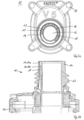
- FIGs 2a and 2b show different views of an upper part 10 of the figure 1 illustrated filler neck 1. It shows the Figure 2a a plan view of the top of the upper part 10 and Figure 2b a lateral sectional view of the in Figure 2a shown upper part 10.
- the upper part 10 comprises a mouth hole socket 11, at the upper end of which a mouth hole opening 12 or a mouth hole 12 is provided.
- a dispensing valve (not shown in the figures) can be introduced into the interior of the filler neck 10 through the mouth opening 12 .
- the upper part 10 comprises four fastening openings 19, through which, for example, fastening screws are passed and with a Figure 6b illustrated lower part 20 of the filler neck 1 can be connected.
- a venting path is provided in the filler neck 1 , which allows a venting flow during refueling parallel and opposite to the refueling volume flow through the mouth hole 11 .
- the vent path includes the in the Figures 2a and 2b illustrated embodiment of the filler neck 1 nine ventilation channels 18, which are enclosed along the longitudinal extent of the mouth hole socket 11 by an outer wall 14a and an inner wall 14b of the wall 14.
- the respective ventilation channels 18 are further separated from one another by radial walls 15 .
- the ventilation channels 18 are consequently designed as passages or bores 18 through the wall 14 of the mouth hole socket 11 .
- the ventilation channels 18 extend over an angle of approximately 300° around the circumference of the mouth hole socket 11 . This can ensure that in the installed position of the filler neck 1, the lower ends of the venting channels 18, for example during a refueling process, are not covered by the operating liquid collected inside the filler neck 1, so that no operating liquid can escape through the venting through the venting channels 18 to the outside of the filler neck 1 reached.
- the respective ventilation channels 18 are conical and taper from the end facing the operating liquid container 3 towards its mouth hole opening 12 .
- This taper is realized in that the distance between the outer wall 14a and the inner wall 14b decreases along the longitudinal extent of the mouth hole connector 11 in the direction of the mouth hole opening 12 .
- This configuration of the upper part 10 of the filler neck 1 can reduce “spitback” and “splashback” during a refueling process and in particular during a refueling process and when switching off the fuel nozzle, since any operating liquid that has penetrated into the venting channel 18 due to the narrowing of the venting channel 18 on the outer wall 14a or on the inner wall 14b can be better deposited.
- the operating liquid then flows again, following gravity, into the lower area of the filler neck 1 and back into the operating liquid container 3 via openings (not shown).
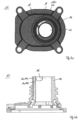
- FIG. 3a to 3c illustrated upper part 10 according to a second embodiment of the present invention differs from the upper part 10 according to the in the Figures 2a and 2b illustrated first embodiment of the invention characterized in that the ventilation path comprises only two ventilation channels 18, which are enclosed along the longitudinal extent of the mouth hole socket 11 by the outer wall 14a and the inner wall 14b of the wall 14.
- the two ventilation channels 18 are separated from each other by a radial wall 15 .
- the ventilation channels 18 extend by approximately 110° around the circumference of the mouth hole socket.
- the cross-sectional areas of the respective vent passages 18 in the upper part 10 according to the second embodiment are larger than the cross-sectional areas of the respective vent passages 18 of the upper part 10 according to the first embodiment of the present invention.
- the total cross-sectional area of the venting channels 18 of the upper part 10 according to the second embodiment is not significantly smaller than the total cross-sectional area of the venting channels 18 of the upper part 10 according to the first embodiment, since there is only a single radial wall 15 between the two venting channels 18 in the upper part 10 according to FIG second embodiment must be provided. Therefore, a high venting volume flow of at least 40 l/min is still achieved.
- the two ventilation channels 18 have a corresponding conical configuration as the ventilation channels 18 of the upper part 10 according to the first embodiment of the present invention.
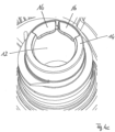
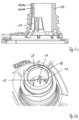
- FIG. 4a to 4c an upper part 10 according to a third embodiment of the filler neck 1 according to the invention is shown, with FIG Figure 4a the upper part 10 in top view, in Figure 4b in side sectional view and in Figure 4c is shown in a spatial view obliquely from above.
- the upper part 10 according to the third embodiment differs from the upper part 10 according to the second embodiment in that the inner wall 14b has material recesses 16 in the area of the mouth hole opening 12 such that the ventilation channels 18 in the area of the mouth hole opening 12 are open towards the interior of the mouth hole connector 11.
- the inner wall 14b consequently has a number of material recesses 16 corresponding to the number of ventilation channels 18 .
- the rest of the design of the upper part 10 according to the third embodiment is identical to the design of the upper part 10 according to the second embodiment.
- a filler neck 1 with the upper part 10 according to the third embodiment has the same positive properties with regard to "spitback” and “splashback” as a filler neck 1 with an upper part 10 according to the second embodiment.
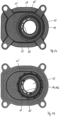
- FIG. 5a to 5d 1 an upper part 10 of a filler neck 1 according to a fourth embodiment of the present invention. While showing Figure 5a the upper part 10 in top view, Figure 5b the underside of the upper part 10 in plan view, Figure 5c the upper part 10 in a lateral sectional view and the Figure 5d the upper part 10 in a spatial representation obliquely from above.
- the upper part 10 according to the fourth embodiment differs from the upper part 10 according to the second embodiment in that the inner wall 14b of the wall 14 surrounding the ventilation ducts 18 has at least one material recess 17 in the region of the end facing away from the mouth opening 12 such that the ventilation ducts 18 in are open towards the interior of the mouth hole socket 11 in the area facing away from the mouth hole opening 12 .
- the two ventilation channels 18 are separated from one another in the area of the material recesses 17 by two further radial walls 15 .
- the radial walls 15 shown to the left and right of the central radial wall 15 are not continuous in the longitudinal extent of the mouth hole socket 10, but only extend in the area of the material recesses 17. Only the central radial wall 15 is continuous along the entire longitudinal extent of the mouth hole socket 11 and separates the two Vent channels 18 from each other.
- the ventilation channels 18 Due to the material recesses 17 in the lower area of the upper part 10, the ventilation channels 18 have an enlarged cross section in the lower area, so that an increased ventilation volume flow is made possible, which in turn enables the operating liquid container 3 to be filled up more quickly.
- the other configuration of the top part 10 of the filler neck 1 according to the fourth embodiment is identical to the top part 10 of the filler neck 1 according to the second embodiment of the present invention.
- a threaded collar 13 is provided on the mouth hole socket 11, onto which a container (not shown) for filling the operating liquid container 3 can be screwed.
- a filler neck 1 according to the present invention can be seen, in which a compensating volume 31 is designed to be enlarged.
- the ring magnet 30 is also held by means of the inner wall 14b and the wall 14 in such a way that the ventilation path is guided along the outside of the ring magnet 30, as a result of which the ventilation capacity is increased again.
- the operating liquid container 3 can be filled up even more quickly, since more gas can be discharged from the operating liquid container 3 per unit of time.
Landscapes
- Engineering & Computer Science (AREA)
- Chemical & Material Sciences (AREA)
- Combustion & Propulsion (AREA)
- Transportation (AREA)
- Mechanical Engineering (AREA)
- Life Sciences & Earth Sciences (AREA)
- Sustainable Development (AREA)
- Sustainable Energy (AREA)
- Closures For Containers (AREA)
- Filling Of Jars Or Cans And Processes For Cleaning And Sealing Jars (AREA)
Description
- Die Erfindung betrifft einen Einfüllstutzen für einen Kraftfahrzeug-Betriebsflüssigkeitsbehälter, wobei der Einfüllstutzen einen Mundlochstutzen umfasst, in den ein Zapfventil zum Befüllen des Betriebsflüssigkeitsbehälters einführbar ist, und wobei in dem Einfüllstutzen ein Entlüftungspfad vorgesehen ist, der bei der Betankung eine Entlüftungsströmung parallel und entgegengesetzt zum Betankungsvolumenstrom durch den Mundlochstutzen zulässt.
- Bei dem Betriebsflüssigkeitsbehälter kann es sich um einen Kraftstoffbehälter, ein Harnstoffbehälter zum Einsatz im SCR-Verfahren (Selektive katalytische Reduktion) oder um einen anderen Kraftfahrzeug-Betriebsflüssigkeitsbehälter handeln.
- Beim Befüllen von Kraftfahrzeug-Betriebsflüssigkeitsbehältern, beispielsweise mittels eines Zapfventils, kann über den Einfüllstutzen Betriebsflüssigkeit austreten. Bei einer Ventilabschaltung mittels Schnüffelbohrung/Abschaltbohrung am Zapfventil führen die hierbei erzeugten Druckstöße zu einer aufwallenden und zurückschwallenden Flüssigkeitsmenge, die je nach Gestaltung des Einfüllstutzens teilweise auch aus dem Einfüllstutzen nach außen hervorspritzen kann. Insbesondere bei der Betankung mit Harnstoff führt dies zu nicht wünschenswerten äußeren Verunreinigungen am Einfüllstutzen und am Fahrzeug.
- So spritzen beim so gennannten "spitback" aufgrund des Abschaltens des Zapfventils und der damit einhergehenden Wellenbildung im Einfüllstutzen Betriebsflüssigkeitstropfen durch Entlüftungsöffnungen aus dem Einfüllstutzen. Beim so genannten "splashback" treten aufgrund des Abschaltens des Zapfventils und/oder aufgrund des Auftreffens der aus dem Zapfventil austretenden Betriebsflüssigkeit auf eine Flüssigkeitssäule während der Betankung größere Flüssigkeitsmengen aus Belüftungsöffnungen des Einfüllstutzens aus.
- Zum einen soll die Entlüftungskapazität, d.h. die pro Zeiteinheit durch Entlüftungseinrichtungen abführbare Gasmenge, von Einfüllstutzen erhöht werden, damit die Zeit zum Befüllen des Betriebsflüssigkeitsbehälters verringert werden kann, und zum anderen soll gleichzeitig der spitback und der splashback reduziert werden. Jedoch sind diese beiden Zielvorgaben bisher nicht miteinander vereinbar, denn umso größer die Entlüftungskapazität eines Einfüllstutzens ist, desto größer müssen die Querschnittsflächen der Entlüftungskanäle sein, was zu einem höheren spitback und splashback des Einfüllstutzens führt.
- Aus der
DE 10 2011 009 745 A1 ist ein Einfüllstutzen bekannt, bei dem der Entlüftungspfad an die Atmosphäre mehrere in Axialrichtung verlaufende Nuten in der Innenwandung des Mundlochstutzens umfasst. Diese Nuten bilden zusammen mit einem in den Mundlochstutzen eingeführten Zapfventil einen Gasaustrittskanal an die Atmosphäre. - Der aus der
DE 10 2011 009 745 A1 bekannte Einfüllstutzen weist bereits gute Entlüftungseigenschaften beim Befüllen des Betriebsflüssigkeitsbehälters auf. Jedoch muss das Zapfventil einen bestimmten Durchmesser aufweisen, damit die Gasaustrittskanäle durch das Nutprofil des Mundlochstutzens und durch die Außenwandung des Zapfventils gebildet und begrenzt sind. Ferner ist die Querschnittsfläche der Gasaustrittskanäle beschränkt, damit der spitback und der splashback nicht übermäßig groß werden. Auch kann sich bei einem zu kleinen Durchmesser des Zapfventils ein Betriebsflüssigkeitsfilm aufgrund des Kapillareffektes zwischen den Profilbergen der Nuten und dem Zapfventil bilden, so dass beim Entlüften die Betriebsflüssigkeit durch den Entlüftungsstrom mitgerissen werden kann. - Die
DE 693 05 024 T2 offenbart einen gattungsbildenden Einfüllstutzen für einen Benzintank. Der Einfüllstutzen umfasst einen kegelstumpfförmigen Körper, wobei in einer ersten Ausführungsform eine Trennwand innerhalb des kegelstumpfförmigen Körpers vorgesehen ist, sodass Entlüftungskanäle gebildet sind, die durch Radialtrennwände voneinander getrennt sind. In einer weiteren Ausführungsform des Einfüllstutzens sind innerhalb des kegelstumpfförmigen Körpers radial vorstehende Wandungen vorgesehen, die Entlüftungskanäle voneinander trennen, die sich durch Einführen eines Zapfventils in den Einfüllstutzen bilden, und zwar durch die Radialvorsprünge mit der Außenwandung des Zapfventils. - Die
DE 20 2005 011 575 U1 offenbart einen gattungsbildenden Einfüllstutzen für einen Behälter. Der Einfüllstutzen umfasst einen Mundlochstutzen, in den ein Zapfventil zum Befüllen des Behälters einführbar ist. In dem Einfüllstutzen ist ein Entlüftungspfad vorgesehen, der bei der Betankung eine Entlüftungsströmung parallel und entgegengesetzt zum Betankungsvolumenstrom durch den Mundlochstutzen zulässt. Dabei umfasst der Entlüftungspfad mehrere in einer Wandung des Mundlochstutzens vorgesehene Entlüftungskanäle, die entlang dessen Längserstreckung von einer Außenwand und einer Innenwand der Wandung umschlossen sind. - Der vorliegenden Erfindung liegt die Aufgabe zugrunde, einen verbesserten Einfüllstutzen bereitzustellen, der eine erhöhte Entlüftungskapazität bei gleichzeitig vermindertem Austritt von Betriebsflüssigkeit durch den Einfüllstutzen während des Befüllvorgangs gewährleistet.
- Die der vorliegenden Erfindung zugrunde liegende Aufgabe wird durch einen Einfüllstutzen mit den Merkmalen des Anspruchs 1 gelöst. Vorteilhafte Ausführungen sind in den Unteransprüchen beschrieben.
- Im Genaueren zeichnet sich der erfindungsgemäße Einfüllstutzen dadurch aus, dass die Innenwand der den Entlüftungskanal/die Entlüftungskanäle umschließenden Wandung im Bereich der Mundlochöffnung zumindest eine derartige Materialausnehmung aufweist, dass der Entlüftungskanal/die Entlüftungskanäle im Bereich der Mundlochöffnung zum Innenraum des Mundlochstutzens hin geöffnet ist/ sind.
- Ein entsprechend ausgebildeter Einfüllstutzen weist verbesserte Entlüftungseigenschaften und einen erhöhten Entlüftungsvolumenstrom auf. Darüber hinaus weist ein entsprechend ausgebildeter Einfüllstutzen eine niedrige Neigung zum "spitback" bzw."splashback" auf. Der Einfüllstutzen umfasst selbstverständlich einen mit dem Mundlochstutzen und mit dem Betriebsflüssigkeitsbehälter fluidverbundenen Einfüllkanal. Der Mundlochstutzen kann auch als Zylinderstutzen bezeichnet werden, und der Entlüftungskanal kann auch als Längskanal, als axial verlaufender Ringspalt oder auch als bogenförmiger Kanal bezeichnet werden. Der Entlüftungskanal ist in Einbauposition des Einfüllstutzens mit dem Betriebsflüssigkeitsbehälterinnenraum und beispielsweise mit der Atmosphäre fluidverbunden.
- Aufgrund der Trennung des Entlüftungskanals von dem Befüllkanal des Einfüllstutzens weist der erfindungsgemäße Einfüllstutzen einen vom Zapfventil unabhängigen Entlüftungsquerschnitt auf. Dadurch ist es möglich, den Entlüftungsquerschnitt im Vergleich zu aus dem Stand der Technik bekannten Einfüllstutzen zu vergrößern, ohne dass der Einfüllstutzen einen vergrößerten "spitback" bzw. "splashback" aufweist.
- Folglich vereint der erfindungsgemäße Einfüllstutzen die bisher miteinander nicht zu vereinbarenden Merkmale eines vergrößerten Entlüftungsquerschnitts der Entlüftungskanäle bzw. des Entlüftungskanals und einer Reduzierung des "spitbacks" bzw. des "splashbacks" beim Betanken des Betriebsflüssigkeitsbehälters. Ferner wird ein sogenannter "Blowout", bei dem während der Betankung aus dem Einfüllkopf bzw. aus dem Einfüllstutzen Flüssigkeitstropfen herausspritzen, vermieden, denn der Entlüftungskanal bzw. die Entlüftungskanäle stehen nicht in direktem Fluidkontakt mit dem Einfüllkanal des Mundlochstutzens.
- Ein weiterer Vorteil des erfindungsgemäßen Einfüllstutzens ist die Möglichkeit, den Standardisierungsgrad von Einfüllstutzen zu erhöhen, da Zapfventile mit unterschiedlichen Durchmessern mit dem erfindungsgemäßen Einfüllstutzen verwendet werden können, sodass für unterschiedliche Zapfventile ein und derselbe Einfüllstutzen verwendet werden kann.
- Der Entlüftungspfad des Einfüllstutzens umfasst zumindest zwei Entlüftungskanäle, die durch eine mit der Innenwand und der Außenwand verbundenen Radialwand voneinander getrennt sind. Ein entsprechend ausgebildeter Einfüllstutzen ist in seiner Herstellung besonders einfach und weist darüber eine hohe mechanische Stabilität auf. Darüber hinaus dient die Radialwand im Falle von "spitback", "splashback" oder "Blowout" auch als eine Wand, an der die entsprechenden Betriebsflüssigkeitstropfen abgeschieden und zurück in Richtung des Einfüllstutzens geleitet werden. Natürlich kann der Entlüftungspfad auch mehr als zwei Entlüftungskanäle umfassen, die jeweils durch eine mit der Innenwand und der Außenwand verbundenen Radialwand voneinander getrennt sind.
- Vorzugsweise ist der Entlüftungskanal bzw. sind die Entlüftungskanäle konisch ausgebildet, wobei sich der Entlüftungskanal bzw. die Entlüftungskanäle von dem dem Betriebsflüssigkeitsbehälter zugewandtem Ende hin zu dessen Mundlochöffnung verjüngt bzw. verjüngen.
- Mit der Verjüngung des Entlüftungskanals bzw. der Entlüftungskanäle kann eine kleiner werdende Querschnittsfläche des Entlüftungskanals/der Entlüftungskanäle einhergehen. Es ist jedoch auch möglich, dass trotz Verjüngung des Entlüftungskanals/der Entlüftungskanäle entlang einer Ausdehnungsrichtung die Querschnittsfläche des Entlüftungskanals/der Entlüftungskanäle entlang dessen Längserstreckung im Wesentlichen konstant bleibt. Dies kann beispielsweise dadurch realisiert werden, dass bei einem entlang der Längserstreckung kleiner werdenden Abstand von sich radial gegenüberstehender Außenwand und Innenwand sich die Breitenerstreckung des Entlüftungskanals/der Entlüftungskanäle im selben Maße vergrößert.
- Durch die Verjüngung des Entlüftungskanals/der Entlüftungskanäle wird der Austritt von Betriebsflüssigkeitströpfchen durch den Entlüftungskanal/die Entlüftungskanäle weiter reduziert, da die Flüssigkeit aufgrund der schräg verlaufenden Begrenzungswände des Entlüftungskanals/der Entlüftungskanäle effektiver abgeschieden und anschließend wieder in Richtung des Einfüllstutzens zurück geleitet werden kann.
- Vorzugsweise weist die Innenwand der dem Entlüftungskanal/der Entlüftungskanäle umschließenden Wandung im Bereich des dem Mundlochöffnung abgewandtem Endes zumindest eine derartige Materialausnehmung auf, dass der Entlüftungskanals/die Entlüftungskanäle in dem der Mundlochöffnung abgewandten Bereich zum Innenraum des Mundlochstutzens hin geöffnet ist/sind.
- Durch eine entsprechende Ausgestaltung des Einfüllstutzens ist die Querschnittsfläche des Entlüftungskanals bzw. der Entlüftungskanäle im unteren Bereich des Einfüllstutzens vergrößert, sodass eine besonders effektive Entlüftung mittels des Einfüllstutzens ermöglicht ist. Zusätzlich kann auch die Außenwand im oberen Bereich des Mundlochstutzens eine Materialausnehmung aufweisen. Ein entsprechend ausgebildeter Einfüllstutzen weist verbesserte Entlüftungseigenschaften und einen erhöhten Entlüftungsvolumenstrom auf. Darüber hinaus weist ein entsprechend ausgebildeter Einfüllstutzen eine niedrige Neigung zum "spitback" bzw. "splashback" auf.
- Vorzugsweise ist in dem Einfüllstutzen ein Ringmagnet vorgesehen, der hinsichtlich der Entlüftungsströmung stromaufwärts und hinsichtlich der Betriebsflüssigkeitseinfüllrichtung stromabwärts vom Mundlochstutzen angeordnet ist.
- Dabei ist der Entlüftungspfad vorzugsweise an der Außenseite des Ringmagneten entlang geführt.
- Bei einer entsprechenden Ausgestaltung des Einfüllstutzens sind der Befüllkanal, über den die Betriebsflüssigkeit in den Betriebsflüssigkeitsbehälter eingefüllt wird, und der Entlüftungskanal vollständig voneinander getrennt. Ferner ist der Entlüftungspfad im Bereich des Ringmagneten nicht durch dessen Innendurchmesser begrenzt, sodass eine verbesserte Entlüftung mit einem hohen Entlüftungsvolumenstrom ermöglicht ist.
- Vorzugsweise ist der Entlüftungskanal/sind die Entlüftungskanäle in Draufsicht auf den Mundlochstutzen in dessen Wandung nicht komplett umlaufend angeordnet.
- Weiter vorzugsweise erstreckt/erstrecken sich in Draufsicht auf den Mundlochstutzen der Entlüftungskanal/die Entlüftungskanäle um weniger als 300° um den Umfang des Mundlochstutzens. Es ist auch möglich, dass sich der Entlüftungskanal/die Entlüftungskanäle um weniger als 270° oder um weniger als 180° um den Umfang des Mundlochstutzens erstrecken.
- Durch eine entsprechende Ausgestaltung des Einfüllstutzens ist es möglich, dass in Einbaulage des Einfüllstutzens der Entlüftungskanal bzw. die Entlüftungskanäle im oberen Bereich des Mundlochstutzens angeordnet sind, sodass die unteren Enden des Entlüftungskanals/der Entlüftungskanäle nicht durch die Betriebsflüssigkeit bedeckt sind, wenn beispielsweise ein Nachtankvorgang durchgeführt wird. Dies wiederum führt dazu, dass die Entlüftungskanäle durch weniger oder gar keine Betriebsflüssigkeit benetzt sind, sodass ein entsprechend ausgebildeter Einfüllstutzen einen verminderten "spitback" bzw. "splashback" aufweist.
- Vorzugsweise weist der Entlüftungskanal bzw. weisen die Entlüftungskanäle in Summe eine Querschnittsfläche zwischen 10 mm2 und 100 mm2 auf.
- Weiter vorzugsweise weist der Entlüftungskanal bzw. weisen die Entlüftungskanäle in Summe eine Querschnittsfläche zwischen 20 mm2 und 80 mm2 auf. Höchst vorzugsweise weist der Entlüftungskanal bzw. weisen die Entlüftungskanäle eine Querschnittsfläche zwischen 40 mm2 und 70 mm2 auf.
- Durch eine entsprechende Ausgestaltung des Einfüllstutzens und eine entsprechende Dimensionierung des Entlüftungskanals bzw. der Entlüftungskanäle kann ein Entlüftungsvolumenstrom von 40 l/min. gewährleistet werden, was für die Betankung des Betriebsflüssigkeitsbehälters wünschenswert ist.
- Weitere Vorteile, Einzelheiten und Merkmale der Erfindung ergeben sich nachfolgend aus den erläuterten Ausführungsbeispielen. Dabei zeigen im Einzelnen:
- Figur 1
- einen Querschnitt durch einen Betriebsflüssigkeitsbehälter mit einem Einfüllstutzen gemäß der Erfindung;
- Figur 2a:
- eine Draufsicht auf die Oberseite des Oberteils eines Einfüllstutzens gemäß einer ersten Ausführungsform der vorliegenden Erfindung;
- Figur 2b:
- ein seitliche Schnittdarstellung des in
Figur 2a dargestellten Oberteils des Einfüllstutzens; - Figur 3a:
- eine Draufsicht auf die Oberseite des Oberteils eines Einfüllstutzens gemäß einer zweiten Ausführungsform der vorliegenden Erfindung;
- Figur 3b:
- eine Draufsicht auf die Unterseite des in
Figur 3a dargestellten Oberteils des Einfüllstutzens; - Figur 3c:
- eine Seitenansicht des in den
Figuren 3a und 3b dargestellten Oberteils des Einfüllstutzens in Schnittdarstellung; - Figur 4a:
- eine Draufsicht auf die Oberseite des Oberteils eines Einfüllstutzens gemäß einer dritten Ausführungsform der vorliegenden Erfindung;
- Figur 4b:
- eine Seitenansicht des in
Figur 4a dargestellten Oberteils des Einfüllstutzens in Schnittdarstellung; - Figur 4c:
- eine räumliche Darstellung des in den
Figuren 4a und 4b dargestellten Oberteils des Einfüllstutzens; - Figur 5a:
- eine Draufsicht auf die Oberseite des Oberteils eines Einfüllstutzens gemäß einer vierten Ausführungsform der vorliegenden Erfindung;
- Figur 5b:
- eine Draufsicht auf die Unterseite des in
Figur 5a dargestellten Oberteils des Einfüllstutzens; - Figur 5c:
- eine Seitenansicht des in den
Figuren 5a und 5b dargestellten Oberteils des Einfüllstutzens; - Figur 5d:
- eine räumliche Darstellung des in den
Figuren 5a, 5b und5c dargestellten Oberteils des Einfüllstutzens; - Figur 6a:
- eine Querschnittsdarstellung durch einen aus dem Stand der Technik bekannten Einfüllstutzen; und
- Figur 6b:
- eine Querschnittsdarstellung durch einen erfindungsgemäßen Einfüllstutzen
- In der nun folgenden Beschreibung bezeichnen gleiche Bezugszeichen gleiche Bauteile bzw. gleiche Merkmale, so dass eine in Bezug auf eine Figur durchgeführte Beschreibung bezüglich eines Bauteils auch für die anderen Figuren gilt, so dass eine wiederholende Beschreibung vermieden wird.
- Wie der
Figur 1 zu entnehmen ist, ist der Einfüllstutzen 1 gemäß der Erfindung an einem Einfüllrohr 2 eines Betriebsflüssigkeitsbehälters 3 angeordnet. Dieser Betriebsflüssigkeitsbehälter ist bei dem beschriebenen Ausführungsbeispiel als Harnstoffbehälter für eine flüssige Harnstofflösung als Reduktionsmittel für die katalytische Abgasentstickung an einem KFZ ausgebildet. - Der Betriebsflüssigkeitsbehälter 3 kann als einstückig ausgebildeter extrusionsblasgeformter Kunststoffbehälter ausgebildet sein. Das Einfüllrohr 2 sowie der Einfüllstutzen 1 können ebenfalls aus thermoplastischem Kunststoff bestehen. Ein Oberteil 10 des Einfüllstutzens 1, das mit Bezug auf die nachfolgenden Figuren beschrieben wird, als auch die übrigen beschriebenen Bauteile können auch im Spritzgießverfahren hergestellt werden. Bei dem beschriebenen Ausführungsbeispiel ist die gesamte Anordnung aus Einfüllstutzen 1, Einfüllrohr 2 und Betriebsflüssigkeitsbehälter 3 mehrteilig. Der Einfüllstutzen 1 ist, wie nachstehend noch beschrieben, als Einfüllkopf mit einem Anschluss 4 für eine Betankungsentlüftungsleitung 5 ausgebildet. Die Betankungsentlüftungsleitung 5 mündet über ein Tauchrohr 6 als Abschaltnippel in einer vorgegebenen Entlüftungsposition in den Betriebsflüssigkeitsbehälter 3.
- Die Betankungsentlüftungsleitung 5 ist von dem Betriebsflüssigkeitsbehälter 3 an den Einfüllstutzen 1 über einen Ausgleichsbehälter 7 geführt, der als Sammelbehälter für etwa in der Betankungsentlüftungsleitung 5 anfallende Flüssigkeit dient. Bei der Befüllung des Betriebsflüssigkeitsbehälters 3 wird über ein in den Figuren nicht dargestelltes Zapfventil eine Harnstofflösung in den Betriebsflüssigkeitsbehälter 3 eingeleitet mit der Folge, dass in diesem der Flüssigkeitsspiegel ansteigt und das in dem Betriebsflüssigkeitsbehälter 3 anstehende Gas über die Betankungsentlüftungsleitung 5 an den Einfüllstutzen 1 verdrängt wird, bis der ansteigende Flüssigkeitsspiegel das Tauchrohr 6 verschließt. Sodann steigt der Flüssigkeitsspiegel im Einfüllrohr 2 an, bis dieser eine Abschaltbohrung 8 an einem in dem Figuren nicht dargestellten Zapfventil erreicht und verschließt, mit der Folge, dass ein Schaltvorgang des Zapfventils ausgelöst wird. Der Betankungsvorgang ist damit beendet.
- Die
Figuren 2a und 2b zeigen unterschiedliche Ansichten eines Oberteils 10 des inFigur 1 dargestellten Einfüllstutzens 1. Dabei zeiget dieFigur 2a eine Draufsicht auf die Oberseite des Oberteils 10 undFigur 2b eine seitliche Schnittdarstellung des inFigur 2a dargestellten Oberteils 10. - Aus den Figuren ist ersichtlich, dass das Oberteil 10 einen Mundlochstutzen 11 umfasst, an dessen oberen Ende eine Mundlochöffnung 12 bzw. ein Mundloch 12 vorgesehen ist. Durch die Mundlochöffnung 12 kann ein in den Figuren nicht dargestelltes Zapfventil in den Innenraum des Einfüllstutzens 10 eingeführt werden.
- Das Oberteil 10 umfasst in der dargestellten Ausführungsform vier Befestigungsöffnungen 19, durch die beispielsweise Befestigungsschrauben hindurchgeführt und mit einem in
Figur 6b dargestellten Unterteil 20 des Einfüllstutzens 1 verbunden werden können. - In dem Einfüllstutzen 1 ist ein Entlüftungspfad vorgesehen, der bei der Betankung eine Entlüftungsströmung parallel und entgegengesetzt zum Betankungsvolumenstrom durch den Mundlochstutzen 11 zulässt. Der Entlüftungspfad umfasst bei der in den
Figuren 2a und 2b dargestellten Ausführungsform des Einfüllstutzens 1 neun Entlüftungskanäle 18, die entlang der Längserstreckung des Mundlochstutzens 11 von einer Außenwand 14a und einer Innenwand 14b der Wandung 14 umschlossen sind. Die jeweiligen Entlüftungskanäle 18 sind ferner durch Radialwände 15 voneinander getrennt. Die Entlüftungskanäle 18 sind folglich als Durchführungen bzw. Bohrungen 18 durch die Wandung 14 des Mundlochstutzens 11 ausgebildet. - Aus der Draufsicht der
Figur 2a ist ersichtlich, dass sich die Entlüftungskanäle 18 über einen Winkel von etwa 300° um den Umfang des Mundlochstutzens 11 erstrecken. Dadurch kann gewährleistet werden, dass in Einbaulage des Einfüllstutzens 1 die unteren Enden der Entlüftungskanäle 18, beispielsweise bei einem Nachbetankungsvorgang, nicht durch innerhalb des Einfüllstutzens 1 gesammelte Betriebsflüssigkeit bedeckt sind, so dass keine Betriebsflüssigkeit durch die Entlüftung durch die Entlüftungskanäle 18 an die Außenseite des Einfüllstutzens 1 gelangt. - Aus
Figur 2b ist ersichtlich, dass die jeweiligen Entlüftungskanäle 18 konisch ausgebildet sind und sich von dem dem Betriebsflüssigkeitsbehälter 3 zugewandtem Ende hin zu dessen Mundlochöffnung 12 verjüngen. Diese Verjüngung ist dadurch realisiert, dass sich der Abstand der Außenwand 14a zu der Innenwand 14b entlang der Längserstreckung des Mundlochstutzens 11 in Richtung der Mundlochöffnung 12 verringert. Durch diese Ausgestaltung des Oberteils 10 des Einfüllstutzens 1 kann "spitback" und "splashback" bei einem Betankungsvorgang und insbesondere bei einem Nachbetankungsvorgang und bei Abschalten des Zapfventils reduziert werden, da eventuell in den Entlüftungskanal 18 eingedrungene Betriebsflüssigkeit aufgrund der Verjüngung des Entlüftungskanals 18 an der Außenwand 14a oder an der Innenwand 14b besser abgeschieden werden kann. Die Betriebsflüssigkeit fließt dann anschließend der Schwerkraft folgend wieder in den unteren Bereich des Einfüllstutzens 1 und über nicht dargestellte Öffnungen wieder zurück in den Betriebsflüssigkeitsbehälter 3. - Das in den
Figuren 3a bis 3c dargestellte Oberteil 10 gemäß einer zweiten Ausführungsform der vorliegenden Erfindung unterscheidet von dem Oberteil 10 gemäß der in denFiguren 2a und 2b dargestellten ersten Ausführungsform der Erfindung dadurch, dass der Entlüftungspfad lediglich zwei Entlüftungskanäle 18 umfasst, die entlang der Längserstreckung des Mundlochstutzens 11 von der Außenwand 14a und der Innenwand 14b der Wandung 14 umschlossen sind. Die zwei Entlüftungskanäle 18 sind durch eine Radialwand 15 voneinander getrennt. - Aus den
Figuren 3a und 3b ist ersichtlich, dass sich in Draufsicht auf den Mundlochstutzen 11 die Entlüftungskanäle 18 um etwa 110°um den Umfang des Mundlochstutzens erstrecken. Die Querschnittsfläche der jeweiligen Entlüftungskanäle 18 in dem Oberteil 10 gemäß der zweiten Ausführungsform sind größer als die Querschnittsflächen der jeweiligen Entlüftungskanäle 18 des Oberteils 10 gemäß der ersten Ausführungsform der vorliegenden Erfindung. - Jedoch ist die gesamte Querschnittsfläche der Entlüftungskanäle 18 des Oberteils 10 gemäß der zweiten Ausführungsform nicht wesentlich kleiner als die gesamte Querschnittsfläche der Entlüftungskanäle 18 des Oberteils 10 gemäß der ersten Ausführungsform, da lediglich eine einzige Radialwand 15 zwischen den zwei Entlüftungskanälen 18 bei dem Oberteil 10 gemäß der zweiten Ausführungsform vorgesehen sein muss. Daher wird weiterhin ein hoher Entlüftungsvolumenstrom von mindestens 40 l/min erreicht.
- Die zwei Entlüftungskanäle 18 weisen eine entsprechende konische Ausgestaltung auf wie die Entlüftungskanäle 18 des Oberteils 10 gemäß der ersten Ausführungsform der vorliegenden Erfindung.
- In den
Figuren 4a bis 4c ist ein Oberteil 10 gemäß einer dritten Ausführungsform des erfindungsgemäßen Einfüllstutzens 1 dargestellt, wobei inFigur 4a das Oberteil 10 in Draufsicht, inFigur 4b in seitlicher Schnittansicht und inFigur 4c in räumlicher Ansicht von schräg oben dargestellt ist. - Das Oberteil 10 gemäß der dritten Ausführungsform unterscheidet von dem Oberteil 10 gemäß der zweiten Ausführungsform dadurch, dass die Innenwand 14b im Bereich der Mundlochöffnung 12 Materialausnehmungen 16 dergestalt aufweist, dass die Entlüftungskanäle 18 im Bereich der Mundlochöffnung 12 zum Innenraum des Mundlochstutzens 11 hin geöffnet sind. Die Innenwand 14b weist folglich eine der Anzahl der Entlüftungskanäle 18 entsprechende Anzahl von Materialausnehmungen 16 auf. Die übrige Ausgestaltung des Oberteils 10 gemäß der dritten Ausführungsform ist identisch mit der Ausgestaltung des Oberteils 10 gemäß der zweiten Ausführungsform.
- Durch die Materialausnehmungen 16 wird die effektive Querschnittsfläche der Entlüftungskanäle 18 im oberen Bereich des Mundlochstutzens 11 vergrößert, so dass sich eine Entlüftungsströmung in den Entlüftungskanälen 18 einstellt. Ferner weist ein Einfüllstutzen 1 mit dem Oberteil 10 gemäß der dritten Ausführungsform die gleichen positiven Eigenschaften hinsichtlich "spitback" und "splashback" auf wie ein Einfüllstutzen 1 mit einem Oberteil 10 gemäß der zweiten Ausführungsform.
- In den
Figuren 5a bis 5d ist ein Oberteil 10 eines Einfüllstutzens 1 gemäß einer vierten Ausführungsform der vorliegenden Erfindung dargestellt. Dabei zeigtFigur 5a das Oberteil 10 in Draufsicht,Figur 5b die Unterseite des Oberteil 10 in Draufsicht,Figur 5c das Oberteil 10 in seitlicher Schnittdarstellung und dieFigur 5d das Oberteil 10 in räumlicher Darstellung von schräg oben. - Das Oberteil 10 gemäß der vierten Ausführungsform unterscheidet sich von dem Oberteil 10 gemäß der zweiten Ausführungsform dadurch, dass die Innenwand 14b der die Entlüftungskanäle 18 umschließenden Wandung 14 im Bereich des der Mundlochöffnung 12 abgewandten Endes zumindest eine derartige Materialausnehmung 17 aufweist, dass die Entlüftungskanäle 18 in dem der Mundlochöffnung 12 abgewandten Bereich zum Innenraum des Mundlochstutzens 11 hin geöffnet sind.
- Ferner sind die zwei Entlüftungskanäle 18 im Bereich der Materialausnehmungen 17 durch zwei weitere Radialwände 15 voneinander getrennt. Diese in
Figur 5a links und rechts von der mittleren Radialwand 15 dargestellten Radialwände 15 sind jedoch in Längserstreckung des Mundlochstutzens 10 nicht durchlaufend, sondern erstrecken sich nur in dem Bereich der Materialausnehmungen 17. Lediglich die mittlere Radialwand 15 ist entlang der gesamten Längserstreckung des Mundlochstutzens 11 durchlaufend und trennt die zwei Entlüftungskanäle 18 voneinander. - Aufgrund der Materialausnehmungen 17 im unteren Bereich des Oberteils 10 weisen die Entlüftungskanäle 18 im unteren Bereich einen vergrößerten Querschnitt auf, sodass ein erhöhter Entlüftungsvolumenstrom ermöglicht wird, was wiederum eine schnellere Betankung des Betriebsflüssigkeitsbehälters 3 ermöglicht. Die übrige Ausgestaltung des Oberteils 10 des Einfüllstutzens 1 gemäß der vierten Ausführung ist identisch mit dem Oberteil 10 des Einfüllstutzens 1 gemäß der zweiten Ausführungsform der vorliegenden Erfindung.
- Bei sämtlichen Oberteilen 10 ist auf dem Mundlochstutzen 11 ein Gewindekragen 13 vorgesehen, auf den ein nicht dargestellter Behälter zum Befüllen des Betriebsflüssigkeitsbehälters 3 geschraubt werden kann.
- Aus
Figur 6a ist ein Querschnitt durch einen aus dem Stand der Technik bekannter Einfüllstutzen dargestellt. Es ist ersichtlich, der Entlüftungspfad durch den Mundlochstutzen nicht von dem Befüllkanal getrennt ist. Ferner ist ersichtlich, dass die Entlüftungsströmung durch den Ringraum des Ringmagneten 30 geführt ist. - Aus
Figur 6b ist ein Einfüllstutzen 1 gemäß der vorliegenden Erfindung ersichtlich, bei dem ein Ausgleichsvolumen 31 vergrößert ausgestaltet ist. Der Ringmagnet 30 ist ferner mittels der Innenwand 14b und der Wandung 14 derart gehalten, dass der Entlüftungspfad an der Außenseite des Ringmagneten 30 entlang geführt ist, wodurch sich die Entlüftungskapazität nochmals erhöht. Dadurch kann der Betriebsflüssigkeitsbehälter 3 nochmals schneller betankt werden, da pro Zeiteinheit mehr Gas aus dem Betriebsflüssigkeitsbehälter 3 abgeleitet werden kann. -
- 1
- Einfüllstutzen
- 2
- Einfüllrohr
- 3
- Betriebsflüssigkeitsbehälter
- 4
- Anschluss für Betankungsentlüftungsleitung
- 5
- Betankungsentlüftungsleitung
- 6
- Tauchrohr
- 7
- Ausgleichsbehälter
- 10
- Oberteil des Einfüllstutzens
- 11
- Mundlochstutzen
- 12
- Mundlochöffnung / Mundloch
- 13
- Gewindekragen
- 14
- Wandung (des Mundlochstutzens)
- 14a
- Außenwand (der Wandung)
- 14b
- Innenwand (der Wandung)
- 15
- Radialwand (zwischen Außenwand und Innenwand)
- 16
- Materialausnehmung
- 17
- Materialausnehmung
- 18
- Entlüftungskanal
- 19
- Befestigungsöffnung
- 20
- Unterteil des Einfüllstutzens
- 30
- Ringmagnet
- 31
- Ausgleichsvolumen
Claims (8)
- Einfüllstutzen (1) für einen Betriebsflüssigkeitsbehälter (3) für ein Kraftfahrzeug, wobei der Einfüllstutzen (1) folgende Merkmale aufweist:- der Einfüllstutzen (1) umfasst einen Mundlochstutzen (11), in den ein Zapfventil zum Befüllen des Betriebsflüssigkeitsbehälters (3) einführbar ist;- in dem Einfüllstutzen (1) ist ein Entlüftungspfad vorgesehen, der bei der Betankung eine Entlüftungsströmung parallel und entgegengesetzt zum Betankungsvolumenstrom durch den Mundlochstutzen (11) zulässt,dadurch gekennzeichnet, dass der Entlüftungspfad zumindest zwei in einer Wandung (14) des Mundlochstutzens (11) vorgesehene Entlüftungskanäle (18) umfasst, die entlang deren Längserstreckung zumindest teilweise von einer Außenwand (14a) und einer Innenwand (14b) der Wandung (14) umschlossen und jeweils durch eine mit der Innenwand (14b) und der Außenwand (14a) verbundenen Radialwand (15) voneinander getrennt sind, wobei die Innenwand (14b) der die Entlüftungskanäle (18) umschließenden Wandung (14) im Bereich der Mundlochöffnung (12) zumindest eine derartige Materialausnehmung (16) aufweist, dass die Entlüftungskanäle (18) im Bereich der Mundlochöffnung (12) zum Innenraum des Mundlochstutzens (11) geöffnet sind.
- Einfüllstutzen nach Anspruch 1, dadurch gekennzeichnet, dass die Entlüftungskanäle (18) konisch ausgebildet sind und sich von dem dem Betriebsflüssigkeitsbehälter (3) zugewandtem Ende hin zu dessen Mundlochöffnung (12) verjüngen.
- Einfüllstutzen (1) nach einem der vorhergehenden Ansprüche, dadurch gekennzeichnet, dass die Innenwand (14b) der die Entlüftungskanäle (18) umschließenden Wandung (14) im Bereich des der Mundlochöffnung (12) abgewandtem Endes zumindest eine derartige Materialausnehmung (17) aufweist, dass die Entlüftungskanäle (18) im der Mundlochöffnung (12) abgewandtem Bereich zum Innenraum des Mundlochstutzens (11) geöffnet sind.
- Einfüllstutzen (1) nach einem der vorhergehenden Ansprüche, dadurch gekennzeichnet, dass in dem Einfüllstutzen (1) ein Ringmagnet (30) vorgesehen ist, der hinsichtlich der Entlüftungsströmung stromaufwärts vom Mundlochstutzen (11) angeordnet ist.
- Einfüllstutzen (1) nach Anspruch 4, dadurch gekennzeichnet, dass der Entlüftungspfad an der Außenseite des Ringmagneten (30) entlang führt.
- Einfüllstutzen (1) nach einem der vorhergehenden Ansprüche, dadurch gekennzeichnet, dass die Entlüftungskanäle (18) in Draufsicht auf den Mundlochstutzen (11) in dessen Wandung (14) nicht komplett umlaufend angeordnet sind.
- Einfüllstutzen (1) nach Anspruch 6, dadurch gekennzeichnet, dass in Draufsicht auf den Mundlochstutzen (11) die Entlüftungskanäle (18) sich um weniger als 300° um den Umfang des Mundlochstutzens (11) erstrecken.
- Einfüllstutzen (1) nach einem der vorhergehenden Ansprüche, dadurch gekennzeichnet, dass die Entlüftungskanäle (18) in Summe eine Querschnittsfläche zwischen 10 mm2 und 100 mm2 aufweisen.
Applications Claiming Priority (2)
| Application Number | Priority Date | Filing Date | Title |
|---|---|---|---|
| DE102013016684.5A DE102013016684B4 (de) | 2013-10-09 | 2013-10-09 | Einfüllstutzen für einen Kraftfahrzeug-Betriebsflüssigkeitsbehälter |
| PCT/EP2014/071409 WO2015052166A1 (de) | 2013-10-09 | 2014-10-07 | Einfüllstutzen für einen kraftfahrzeug-betriebsflüssigkeitsbehälter |
Publications (3)
| Publication Number | Publication Date |
|---|---|
| EP3055156A1 EP3055156A1 (de) | 2016-08-17 |
| EP3055156B1 EP3055156B1 (de) | 2018-02-21 |
| EP3055156B2 true EP3055156B2 (de) | 2023-05-17 |
Family
ID=51662110
Family Applications (1)
| Application Number | Title | Priority Date | Filing Date |
|---|---|---|---|
| EP14781192.1A Active EP3055156B2 (de) | 2013-10-09 | 2014-10-07 | Einfüllstutzen für einen kraftfahrzeug-betriebsflüssigkeitsbehälter |
Country Status (6)
| Country | Link |
|---|---|
| US (1) | US9776502B2 (de) |
| EP (1) | EP3055156B2 (de) |
| KR (1) | KR101691339B1 (de) |
| CN (1) | CN105682969B (de) |
| DE (1) | DE102013016684B4 (de) |
| WO (1) | WO2015052166A1 (de) |
Families Citing this family (6)
| Publication number | Priority date | Publication date | Assignee | Title |
|---|---|---|---|---|
| DE102014007706A1 (de) * | 2014-05-28 | 2015-12-03 | Kautex Textron Gmbh & Co. Kg | Vorratsbehälter in einem Kfz |
| KR102261541B1 (ko) * | 2017-02-15 | 2021-06-04 | 현대자동차주식회사 | 디젤 차량의 요소수 충진 장치 |
| DE102018118272A1 (de) * | 2018-07-27 | 2020-01-30 | Kautex Textron Gmbh & Co. Kg | Einfüllstutzen für druckloses Betankungsabschalten und Nachtanken und Betriebsflüssigkeitsbehälter mit Einfüllstutzen |
| DE102020123321A1 (de) | 2020-09-07 | 2022-03-10 | Röchling Automotive SE & Co. KG | Befüllköpfe |
| DE102020124193A1 (de) | 2020-09-16 | 2022-03-17 | Röchling Automotive SE & Co. KG | Befüllkopf |
| USD998712S1 (en) * | 2021-08-10 | 2023-09-12 | Pacoware Inc. | Block play board |
Citations (8)
| Publication number | Priority date | Publication date | Assignee | Title |
|---|---|---|---|---|
| US3133564A (en) † | 1960-11-10 | 1964-05-19 | Chrysler Corp | Anti-spit-back fill pipe |
| US3187936A (en) † | 1962-11-01 | 1965-06-08 | Gen Motors Corp | Integral fuel filler pipe and vent tube |
| DE202007018245U1 (de) † | 2007-12-21 | 2009-04-30 | Reutter Gmbh | Adapter für einen Einfüllstutzen eines Harnstoffbehälters |
| US20090321441A1 (en) † | 2005-07-13 | 2009-12-31 | Reutter Gmbh | Filler tube for a tank |
| FR2936837A1 (fr) † | 2008-10-03 | 2010-04-09 | Inergy Automotive Systems Res | Integration du tube d'aeration sur le tuyau de remplissage d'un reservoir de fluide de depollution pour gaz d'echappement |
| DE102011009754A1 (de) † | 2011-01-28 | 2012-08-02 | Heraeus Sensor Technology Gmbh | Strömungssensoren mit Stromdurchführung im Deckel und Sensorspitze als Zwischenprodukt |
| WO2012100906A2 (en) † | 2011-01-28 | 2012-08-02 | Kautex Textron Gmbh & Co.Kg | Filler neck for an auxiliary liquid reservoir |
| WO2013034575A1 (de) † | 2011-09-05 | 2013-03-14 | Reutter Gmbh | Einfüllstutzen für einen flüssigkeitsvorratsbehälter eines kraftfahrzeugs mit einem integrierten entlüftungskanal |
Family Cites Families (19)
| Publication number | Priority date | Publication date | Assignee | Title |
|---|---|---|---|---|
| IT206208Z2 (it) * | 1985-11-15 | 1987-07-13 | Italiana Serrature Torino | Organo di adduzione carburante per veicoli |
| US4816045A (en) * | 1986-03-31 | 1989-03-28 | Stant Inc. | Vapor recovery system |
| US5103877A (en) * | 1991-04-15 | 1992-04-14 | General Motors Corporation | Vapor-liquid separator for evaporative emissions control system |
| US5195566A (en) * | 1991-05-01 | 1993-03-23 | Mecrom Ott & Holey Ohg | Cap for the filler neck of liquid containers |
| FR2693957B1 (fr) * | 1992-07-27 | 1994-10-14 | Renault | Pipe de remplissage de réservoir de carburant. |
| US5275213A (en) * | 1993-01-22 | 1994-01-04 | Perko, Inc. | Fuel filling and venting device |
| US5503199A (en) * | 1994-03-21 | 1996-04-02 | Attwood Corporation | Fuel fill devices for boats |
| DE19819779A1 (de) * | 1998-05-04 | 1999-11-11 | Mannesmann Vdo Ag | Kraftstoffbehälter |
| US6032821A (en) * | 1998-06-03 | 2000-03-07 | United States Filter Corporation | Center opening treatment tank |
| DE19850904C2 (de) * | 1998-11-05 | 2000-10-05 | Mannesmann Vdo Ag | Einfüllstutzen für einen Kraftstoffbehälter eines Kraftfahrzeugs |
| BE1012907A3 (fr) * | 1999-09-22 | 2001-05-08 | Solvay | Systeme et procede d'obturation d'une ouverture d'un reservoir. |
| US6571836B2 (en) * | 2001-06-13 | 2003-06-03 | Deere & Company | Filler cup for fluid filter |
| US6834770B2 (en) * | 2003-02-26 | 2004-12-28 | Hsiang Tzer Enterprise Co., Ltd. | Fuel inlet structure for vessel |
| US20070108211A1 (en) | 2005-11-14 | 2007-05-17 | Gem Products, Inc. | Fill system for fuel and liquid |
| US7360565B2 (en) * | 2006-06-20 | 2008-04-22 | University Of Maine System | Fuel overflow prevention device |
| JP5048452B2 (ja) * | 2007-10-23 | 2012-10-17 | 本田技研工業株式会社 | 車両用燃料タンクの給油口装置 |
| US9096124B2 (en) * | 2008-04-02 | 2015-08-04 | Brunswick Corporation | Fuel cap apparatus for use with fuel venting systems |
| WO2012020313A2 (en) * | 2010-08-11 | 2012-02-16 | Emco Wheaton Corp. | Adaptor for fluid tank |
| US9409476B2 (en) | 2010-09-25 | 2016-08-09 | Brunswick Corporation | Fuel fill apparatus for use with fuel delivery systems |
-
2013
- 2013-10-09 DE DE102013016684.5A patent/DE102013016684B4/de active Active
-
2014
- 2014-10-07 CN CN201480055777.6A patent/CN105682969B/zh active Active
- 2014-10-07 WO PCT/EP2014/071409 patent/WO2015052166A1/de active Application Filing
- 2014-10-07 KR KR1020167012162A patent/KR101691339B1/ko active IP Right Grant
- 2014-10-07 US US15/028,683 patent/US9776502B2/en active Active
- 2014-10-07 EP EP14781192.1A patent/EP3055156B2/de active Active
Patent Citations (8)
| Publication number | Priority date | Publication date | Assignee | Title |
|---|---|---|---|---|
| US3133564A (en) † | 1960-11-10 | 1964-05-19 | Chrysler Corp | Anti-spit-back fill pipe |
| US3187936A (en) † | 1962-11-01 | 1965-06-08 | Gen Motors Corp | Integral fuel filler pipe and vent tube |
| US20090321441A1 (en) † | 2005-07-13 | 2009-12-31 | Reutter Gmbh | Filler tube for a tank |
| DE202007018245U1 (de) † | 2007-12-21 | 2009-04-30 | Reutter Gmbh | Adapter für einen Einfüllstutzen eines Harnstoffbehälters |
| FR2936837A1 (fr) † | 2008-10-03 | 2010-04-09 | Inergy Automotive Systems Res | Integration du tube d'aeration sur le tuyau de remplissage d'un reservoir de fluide de depollution pour gaz d'echappement |
| DE102011009754A1 (de) † | 2011-01-28 | 2012-08-02 | Heraeus Sensor Technology Gmbh | Strömungssensoren mit Stromdurchführung im Deckel und Sensorspitze als Zwischenprodukt |
| WO2012100906A2 (en) † | 2011-01-28 | 2012-08-02 | Kautex Textron Gmbh & Co.Kg | Filler neck for an auxiliary liquid reservoir |
| WO2013034575A1 (de) † | 2011-09-05 | 2013-03-14 | Reutter Gmbh | Einfüllstutzen für einen flüssigkeitsvorratsbehälter eines kraftfahrzeugs mit einem integrierten entlüftungskanal |
Also Published As
| Publication number | Publication date |
|---|---|
| CN105682969B (zh) | 2017-12-12 |
| DE102013016684B4 (de) | 2019-01-17 |
| KR101691339B1 (ko) | 2016-12-29 |
| US9776502B2 (en) | 2017-10-03 |
| KR20160058965A (ko) | 2016-05-25 |
| CN105682969A (zh) | 2016-06-15 |
| EP3055156A1 (de) | 2016-08-17 |
| EP3055156B1 (de) | 2018-02-21 |
| DE102013016684A1 (de) | 2015-04-09 |
| US20160263989A1 (en) | 2016-09-15 |
| WO2015052166A1 (de) | 2015-04-16 |
Similar Documents
| Publication | Publication Date | Title |
|---|---|---|
| EP3055156B2 (de) | Einfüllstutzen für einen kraftfahrzeug-betriebsflüssigkeitsbehälter | |
| DE102011009745B4 (de) | Einfüllstutzen für einen Nebenflüssigkeitsbehälter | |
| DE102013016683A1 (de) | Einfülleinrichtung für einen Kraftfahrzeug-Betriebsflüssigkeitsbehälter | |
| EP2789490B1 (de) | Befüllkopf für einen Flüssigkeitstank | |
| DE3143612A1 (de) | "spruehdose" | |
| EP1004777B1 (de) | Saugstrahlpumpe | |
| DE102013200177A1 (de) | Dämpfungseinrichtung in einer hydraulischen Strecke | |
| EP3348804B1 (de) | Schmiermittelbehälter für ein hydrauliksystem | |
| WO2020020696A2 (de) | Einfüllstutzen für druckloses betankungsabschalten und nachtanken und betriebsflüssigkeitsbehälter mit einfüllstutzen | |
| EP1186457B1 (de) | Kraftstofftank | |
| EP3390788B1 (de) | Tanksystem für ein reduktionsmittel | |
| EP3241781B1 (de) | Tube mit drosseleinsatz | |
| EP2607133B1 (de) | Füllrohranordnung für einen Flüssigkeitsvorratsbehälter für Kraftfahrzeuge | |
| WO2000024616A1 (de) | Düsenelement für eine scheibenwaschanlage eines kraftfahrzeugs | |
| DE102012210995A1 (de) | Saugstrahlpumpe mit integriertem Filtermodul | |
| EP3551335B1 (de) | Flüssigkeitsstrahldüse | |
| EP3236033B1 (de) | Kombinationsventil zum befüllen und entlüften eines flüssigkeitstanks | |
| WO2018104265A1 (de) | Flüssigkeitsstrahl-verschlussdüse | |
| EP3795227B1 (de) | Filtervorrichtung | |
| WO2017207343A1 (de) | Betankungsarmatur zur betankung eines kraftfahrzeugs mit einem gasförmigen kraftstoff | |
| EP3418095B1 (de) | Entlüftungsnippel und tankvorrichtung | |
| EP3717293B1 (de) | Füllstandsventil für eine druckausgleichsleitung einer fluidtankanordnung sowie entsprechende fluidtankanordnung | |
| DE102014206954A1 (de) | Kraftstofffilter einer Brennkraftmaschine | |
| EP3533650B1 (de) | Kraftstoffbefüllvorrichtung | |
| DE102021211490B4 (de) | Kraftfahrzeugschwingungsdämpfer mit einem hydraulischen Endanschlag |
Legal Events
| Date | Code | Title | Description |
|---|---|---|---|
| PUAI | Public reference made under article 153(3) epc to a published international application that has entered the european phase |
Free format text: ORIGINAL CODE: 0009012 |
|
| 17P | Request for examination filed |
Effective date: 20160509 |
|
| AK | Designated contracting states |
Kind code of ref document: A1 Designated state(s): AL AT BE BG CH CY CZ DE DK EE ES FI FR GB GR HR HU IE IS IT LI LT LU LV MC MK MT NL NO PL PT RO RS SE SI SK SM TR |
|
| AX | Request for extension of the european patent |
Extension state: BA ME |
|
| DAX | Request for extension of the european patent (deleted) | ||
| REG | Reference to a national code |
Ref country code: DE Ref legal event code: R079 Ref document number: 502014007353 Country of ref document: DE Free format text: PREVIOUS MAIN CLASS: B60K0015040000 Ipc: B60K0015035000 |
|
| GRAP | Despatch of communication of intention to grant a patent |
Free format text: ORIGINAL CODE: EPIDOSNIGR1 |
|
| STAA | Information on the status of an ep patent application or granted ep patent |
Free format text: STATUS: GRANT OF PATENT IS INTENDED |
|
| RIC1 | Information provided on ipc code assigned before grant |
Ipc: B60K 15/035 20060101AFI20170922BHEP Ipc: B60K 15/04 20060101ALI20170922BHEP Ipc: B60K 13/04 20060101ALI20170922BHEP |
|
| INTG | Intention to grant announced |
Effective date: 20171019 |
|
| GRAS | Grant fee paid |
Free format text: ORIGINAL CODE: EPIDOSNIGR3 |
|
| GRAA | (expected) grant |
Free format text: ORIGINAL CODE: 0009210 |
|
| STAA | Information on the status of an ep patent application or granted ep patent |
Free format text: STATUS: THE PATENT HAS BEEN GRANTED |
|
| AK | Designated contracting states |
Kind code of ref document: B1 Designated state(s): AL AT BE BG CH CY CZ DE DK EE ES FI FR GB GR HR HU IE IS IT LI LT LU LV MC MK MT NL NO PL PT RO RS SE SI SK SM TR |
|
| REG | Reference to a national code |
Ref country code: GB Ref legal event code: FG4D Free format text: NOT ENGLISH |
|
| REG | Reference to a national code |
Ref country code: CH Ref legal event code: EP |
|
| REG | Reference to a national code |
Ref country code: AT Ref legal event code: REF Ref document number: 971325 Country of ref document: AT Kind code of ref document: T Effective date: 20180315 |
|
| REG | Reference to a national code |
Ref country code: IE Ref legal event code: FG4D Free format text: LANGUAGE OF EP DOCUMENT: GERMAN |
|
| REG | Reference to a national code |
Ref country code: DE Ref legal event code: R096 Ref document number: 502014007353 Country of ref document: DE |
|
| REG | Reference to a national code |
Ref country code: NL Ref legal event code: MP Effective date: 20180221 |
|
| REG | Reference to a national code |
Ref country code: LT Ref legal event code: MG4D |
|
| PG25 | Lapsed in a contracting state [announced via postgrant information from national office to epo] |
Ref country code: ES Free format text: LAPSE BECAUSE OF FAILURE TO SUBMIT A TRANSLATION OF THE DESCRIPTION OR TO PAY THE FEE WITHIN THE PRESCRIBED TIME-LIMIT Effective date: 20180221 Ref country code: LT Free format text: LAPSE BECAUSE OF FAILURE TO SUBMIT A TRANSLATION OF THE DESCRIPTION OR TO PAY THE FEE WITHIN THE PRESCRIBED TIME-LIMIT Effective date: 20180221 Ref country code: NL Free format text: LAPSE BECAUSE OF FAILURE TO SUBMIT A TRANSLATION OF THE DESCRIPTION OR TO PAY THE FEE WITHIN THE PRESCRIBED TIME-LIMIT Effective date: 20180221 Ref country code: CY Free format text: LAPSE BECAUSE OF FAILURE TO SUBMIT A TRANSLATION OF THE DESCRIPTION OR TO PAY THE FEE WITHIN THE PRESCRIBED TIME-LIMIT Effective date: 20180221 Ref country code: NO Free format text: LAPSE BECAUSE OF FAILURE TO SUBMIT A TRANSLATION OF THE DESCRIPTION OR TO PAY THE FEE WITHIN THE PRESCRIBED TIME-LIMIT Effective date: 20180521 Ref country code: FI Free format text: LAPSE BECAUSE OF FAILURE TO SUBMIT A TRANSLATION OF THE DESCRIPTION OR TO PAY THE FEE WITHIN THE PRESCRIBED TIME-LIMIT Effective date: 20180221 Ref country code: HR Free format text: LAPSE BECAUSE OF FAILURE TO SUBMIT A TRANSLATION OF THE DESCRIPTION OR TO PAY THE FEE WITHIN THE PRESCRIBED TIME-LIMIT Effective date: 20180221 |
|
| PG25 | Lapsed in a contracting state [announced via postgrant information from national office to epo] |
Ref country code: GR Free format text: LAPSE BECAUSE OF FAILURE TO SUBMIT A TRANSLATION OF THE DESCRIPTION OR TO PAY THE FEE WITHIN THE PRESCRIBED TIME-LIMIT Effective date: 20180522 Ref country code: RS Free format text: LAPSE BECAUSE OF FAILURE TO SUBMIT A TRANSLATION OF THE DESCRIPTION OR TO PAY THE FEE WITHIN THE PRESCRIBED TIME-LIMIT Effective date: 20180221 Ref country code: BG Free format text: LAPSE BECAUSE OF FAILURE TO SUBMIT A TRANSLATION OF THE DESCRIPTION OR TO PAY THE FEE WITHIN THE PRESCRIBED TIME-LIMIT Effective date: 20180521 Ref country code: SE Free format text: LAPSE BECAUSE OF FAILURE TO SUBMIT A TRANSLATION OF THE DESCRIPTION OR TO PAY THE FEE WITHIN THE PRESCRIBED TIME-LIMIT Effective date: 20180221 Ref country code: LV Free format text: LAPSE BECAUSE OF FAILURE TO SUBMIT A TRANSLATION OF THE DESCRIPTION OR TO PAY THE FEE WITHIN THE PRESCRIBED TIME-LIMIT Effective date: 20180221 |
|
| PG25 | Lapsed in a contracting state [announced via postgrant information from national office to epo] |
Ref country code: MT Free format text: LAPSE BECAUSE OF FAILURE TO SUBMIT A TRANSLATION OF THE DESCRIPTION OR TO PAY THE FEE WITHIN THE PRESCRIBED TIME-LIMIT Effective date: 20180221 |
|
| REG | Reference to a national code |
Ref country code: FR Ref legal event code: PLFP Year of fee payment: 5 |
|
| PG25 | Lapsed in a contracting state [announced via postgrant information from national office to epo] |
Ref country code: IT Free format text: LAPSE BECAUSE OF FAILURE TO SUBMIT A TRANSLATION OF THE DESCRIPTION OR TO PAY THE FEE WITHIN THE PRESCRIBED TIME-LIMIT Effective date: 20180221 Ref country code: RO Free format text: LAPSE BECAUSE OF FAILURE TO SUBMIT A TRANSLATION OF THE DESCRIPTION OR TO PAY THE FEE WITHIN THE PRESCRIBED TIME-LIMIT Effective date: 20180221 Ref country code: PL Free format text: LAPSE BECAUSE OF FAILURE TO SUBMIT A TRANSLATION OF THE DESCRIPTION OR TO PAY THE FEE WITHIN THE PRESCRIBED TIME-LIMIT Effective date: 20180221 Ref country code: AL Free format text: LAPSE BECAUSE OF FAILURE TO SUBMIT A TRANSLATION OF THE DESCRIPTION OR TO PAY THE FEE WITHIN THE PRESCRIBED TIME-LIMIT Effective date: 20180221 Ref country code: EE Free format text: LAPSE BECAUSE OF FAILURE TO SUBMIT A TRANSLATION OF THE DESCRIPTION OR TO PAY THE FEE WITHIN THE PRESCRIBED TIME-LIMIT Effective date: 20180221 |
|
| REG | Reference to a national code |
Ref country code: DE Ref legal event code: R026 Ref document number: 502014007353 Country of ref document: DE |
|
| PLBI | Opposition filed |
Free format text: ORIGINAL CODE: 0009260 |
|
| PG25 | Lapsed in a contracting state [announced via postgrant information from national office to epo] |
Ref country code: DK Free format text: LAPSE BECAUSE OF FAILURE TO SUBMIT A TRANSLATION OF THE DESCRIPTION OR TO PAY THE FEE WITHIN THE PRESCRIBED TIME-LIMIT Effective date: 20180221 Ref country code: SM Free format text: LAPSE BECAUSE OF FAILURE TO SUBMIT A TRANSLATION OF THE DESCRIPTION OR TO PAY THE FEE WITHIN THE PRESCRIBED TIME-LIMIT Effective date: 20180221 Ref country code: CZ Free format text: LAPSE BECAUSE OF FAILURE TO SUBMIT A TRANSLATION OF THE DESCRIPTION OR TO PAY THE FEE WITHIN THE PRESCRIBED TIME-LIMIT Effective date: 20180221 Ref country code: SK Free format text: LAPSE BECAUSE OF FAILURE TO SUBMIT A TRANSLATION OF THE DESCRIPTION OR TO PAY THE FEE WITHIN THE PRESCRIBED TIME-LIMIT Effective date: 20180221 |
|
| PLAX | Notice of opposition and request to file observation + time limit sent |
Free format text: ORIGINAL CODE: EPIDOSNOBS2 |
|
| 26 | Opposition filed |
Opponent name: PLASTIC OMNIUM ADVANCED INNOVATION AND RESEARCH Effective date: 20181120 |
|
| PG25 | Lapsed in a contracting state [announced via postgrant information from national office to epo] |
Ref country code: SI Free format text: LAPSE BECAUSE OF FAILURE TO SUBMIT A TRANSLATION OF THE DESCRIPTION OR TO PAY THE FEE WITHIN THE PRESCRIBED TIME-LIMIT Effective date: 20180221 |
|
| PLBB | Reply of patent proprietor to notice(s) of opposition received |
Free format text: ORIGINAL CODE: EPIDOSNOBS3 |
|
| REG | Reference to a national code |
Ref country code: CH Ref legal event code: PL |
|
| REG | Reference to a national code |
Ref country code: BE Ref legal event code: MM Effective date: 20181031 |
|
| PG25 | Lapsed in a contracting state [announced via postgrant information from national office to epo] |
Ref country code: LU Free format text: LAPSE BECAUSE OF NON-PAYMENT OF DUE FEES Effective date: 20181007 Ref country code: MC Free format text: LAPSE BECAUSE OF FAILURE TO SUBMIT A TRANSLATION OF THE DESCRIPTION OR TO PAY THE FEE WITHIN THE PRESCRIBED TIME-LIMIT Effective date: 20180221 |
|
| REG | Reference to a national code |
Ref country code: IE Ref legal event code: MM4A |
|
| PG25 | Lapsed in a contracting state [announced via postgrant information from national office to epo] |
Ref country code: LI Free format text: LAPSE BECAUSE OF NON-PAYMENT OF DUE FEES Effective date: 20181031 Ref country code: CH Free format text: LAPSE BECAUSE OF NON-PAYMENT OF DUE FEES Effective date: 20181031 Ref country code: BE Free format text: LAPSE BECAUSE OF NON-PAYMENT OF DUE FEES Effective date: 20181031 |
|
| PG25 | Lapsed in a contracting state [announced via postgrant information from national office to epo] |
Ref country code: IE Free format text: LAPSE BECAUSE OF NON-PAYMENT OF DUE FEES Effective date: 20181007 |
|
| PG25 | Lapsed in a contracting state [announced via postgrant information from national office to epo] |
Ref country code: TR Free format text: LAPSE BECAUSE OF FAILURE TO SUBMIT A TRANSLATION OF THE DESCRIPTION OR TO PAY THE FEE WITHIN THE PRESCRIBED TIME-LIMIT Effective date: 20180221 |
|
| PG25 | Lapsed in a contracting state [announced via postgrant information from national office to epo] |
Ref country code: PT Free format text: LAPSE BECAUSE OF FAILURE TO SUBMIT A TRANSLATION OF THE DESCRIPTION OR TO PAY THE FEE WITHIN THE PRESCRIBED TIME-LIMIT Effective date: 20180221 |
|
| PG25 | Lapsed in a contracting state [announced via postgrant information from national office to epo] |
Ref country code: MK Free format text: LAPSE BECAUSE OF NON-PAYMENT OF DUE FEES Effective date: 20180221 Ref country code: HU Free format text: LAPSE BECAUSE OF FAILURE TO SUBMIT A TRANSLATION OF THE DESCRIPTION OR TO PAY THE FEE WITHIN THE PRESCRIBED TIME-LIMIT; INVALID AB INITIO Effective date: 20141007 |
|
| PG25 | Lapsed in a contracting state [announced via postgrant information from national office to epo] |
Ref country code: IS Free format text: LAPSE BECAUSE OF FAILURE TO SUBMIT A TRANSLATION OF THE DESCRIPTION OR TO PAY THE FEE WITHIN THE PRESCRIBED TIME-LIMIT Effective date: 20180621 |
|
| REG | Reference to a national code |
Ref country code: AT Ref legal event code: MM01 Ref document number: 971325 Country of ref document: AT Kind code of ref document: T Effective date: 20191007 |
|
| PG25 | Lapsed in a contracting state [announced via postgrant information from national office to epo] |
Ref country code: AT Free format text: LAPSE BECAUSE OF NON-PAYMENT OF DUE FEES Effective date: 20191007 |
|
| APBM | Appeal reference recorded |
Free format text: ORIGINAL CODE: EPIDOSNREFNO |
|
| APBP | Date of receipt of notice of appeal recorded |
Free format text: ORIGINAL CODE: EPIDOSNNOA2O |
|
| APAH | Appeal reference modified |
Free format text: ORIGINAL CODE: EPIDOSCREFNO |
|
| APBU | Appeal procedure closed |
Free format text: ORIGINAL CODE: EPIDOSNNOA9O |
|
| PUAH | Patent maintained in amended form |
Free format text: ORIGINAL CODE: 0009272 |
|
| STAA | Information on the status of an ep patent application or granted ep patent |
Free format text: STATUS: PATENT MAINTAINED AS AMENDED |
|
| 27A | Patent maintained in amended form |
Effective date: 20230517 |
|
| AK | Designated contracting states |
Kind code of ref document: B2 Designated state(s): AL AT BE BG CH CY CZ DE DK EE ES FI FR GB GR HR HU IE IS IT LI LT LU LV MC MK MT NL NO PL PT RO RS SE SI SK SM TR |
|
| REG | Reference to a national code |
Ref country code: DE Ref legal event code: R102 Ref document number: 502014007353 Country of ref document: DE |
|
| P01 | Opt-out of the competence of the unified patent court (upc) registered |
Effective date: 20230526 |
|
| PGFP | Annual fee paid to national office [announced via postgrant information from national office to epo] |
Ref country code: GB Payment date: 20231020 Year of fee payment: 10 |
|
| PGFP | Annual fee paid to national office [announced via postgrant information from national office to epo] |
Ref country code: FR Payment date: 20231026 Year of fee payment: 10 Ref country code: DE Payment date: 20230926 Year of fee payment: 10 |