EP1004777B1 - Saugstrahlpumpe - Google Patents
Saugstrahlpumpe Download PDFInfo
- Publication number
- EP1004777B1 EP1004777B1 EP99123142A EP99123142A EP1004777B1 EP 1004777 B1 EP1004777 B1 EP 1004777B1 EP 99123142 A EP99123142 A EP 99123142A EP 99123142 A EP99123142 A EP 99123142A EP 1004777 B1 EP1004777 B1 EP 1004777B1
- Authority
- EP
- European Patent Office
- Prior art keywords
- jet
- suction
- nozzle
- propulsion
- jet pump
- Prior art date
- Legal status (The legal status is an assumption and is not a legal conclusion. Google has not performed a legal analysis and makes no representation as to the accuracy of the status listed.)
- Expired - Lifetime
Links
Images
Classifications
-
- F—MECHANICAL ENGINEERING; LIGHTING; HEATING; WEAPONS; BLASTING
- F02—COMBUSTION ENGINES; HOT-GAS OR COMBUSTION-PRODUCT ENGINE PLANTS
- F02M—SUPPLYING COMBUSTION ENGINES IN GENERAL WITH COMBUSTIBLE MIXTURES OR CONSTITUENTS THEREOF
- F02M37/00—Apparatus or systems for feeding liquid fuel from storage containers to carburettors or fuel-injection apparatus; Arrangements for purifying liquid fuel specially adapted for, or arranged on, internal-combustion engines
-
- F—MECHANICAL ENGINEERING; LIGHTING; HEATING; WEAPONS; BLASTING
- F04—POSITIVE - DISPLACEMENT MACHINES FOR LIQUIDS; PUMPS FOR LIQUIDS OR ELASTIC FLUIDS
- F04F—PUMPING OF FLUID BY DIRECT CONTACT OF ANOTHER FLUID OR BY USING INERTIA OF FLUID TO BE PUMPED; SIPHONS
- F04F5/00—Jet pumps, i.e. devices in which flow is induced by pressure drop caused by velocity of another fluid flow
- F04F5/44—Component parts, details, or accessories not provided for in, or of interest apart from, groups F04F5/02 - F04F5/42
- F04F5/46—Arrangements of nozzles
- F04F5/463—Arrangements of nozzles with provisions for mixing
Definitions
- the invention relates to a suction jet pump with improved suction.
- Suction jet pumps are used for example in fuel tanks of Motor vehicles used to fuel from an area of the fuel tank to promote another area.
- Suction jet pumps are nowadays in fuel tanks of motor vehicles used and are known. You have the job of fuel off distant and deeper areas of the fuel tank to the conveyor unit or to promote it in a swirl pot.
- the suction jet pump consists essentially from a motive jet pipe, a suction opening and a Mixing tube.
- the quantity supplied via the motive jet tube of the ejector pump on liquid occurs under pressure from the fürstrahlrohr limiting Drive jet nozzle off and then into the mixing tube.
- the intake opening for the liquid to be conveyed is between the propulsion jet and the Mixing tube arranged.
- the entering into the mixing tube maschinehl generated before the mixing tube a negative pressure, so that the liquid to be conveyed on the Suction opening is sucked into the mixing tube.
- the efficiency of a Suction jet pump depends on many factors. For example, influence the length of the mixing tube and other geometric factors Efficiency.
- the general disadvantage of suction jet pumps consists in its relatively low efficiency of about 20 up to 30%.
- the invention is therefore based on the object, a suction jet pump to create with improved suction, the is simple and does not take up much space.
- the problem is solved with the features of claim 1.
- Advantageous embodiments are in the claims 2 to 8 described.
- suction jet pump according to the invention consists in their known suction jet pumps improved suction, the on the fast liquid closure in the diffuser is returned.
- suction jet pump owns a very simple structure and requires little Space.
- the diffuser in this case an elliptical adapted to the flat jet Intake cone.
- a nozzle opening which is a transversely has extending notch.
- the propulsion jet is fan-shaped widened.
- the Nozzle opening arranged a web that divides the propulsion jet and thus generates the flat jet.
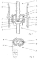
- FIG. 1 a section through an inventive suction jet pump
- Figure 2 shows the top view on the mixing tube with elliptical diffuser.
- the suction jet pump shown in Figure 1 consists of a Upper part 1 and a lower part 2.
- the upper part 1 has a Connecting piece 3 for a jet jet line, not shown, through which the propellant of the suction jet pump is supplied.
- At the connection piece 3 closes the Examstrahldüse 5 with its nozzle opening 6 at.
- a cross extending notch 7 causes the fan-shaped expansion of the Driving jet.
- the lower part 2 of the suction jet pump is from Mixing tube 8 and the diffuser 9 is formed, wherein the diffuser. 9 in an inner housing part 10 passes.
- This inner housing part 10 is inserted into the outer housing part 4 latching and by means of a sealing ring 11 with the upper part of the first tightly connected.
- a suction port forming nozzle 12 At the periphery of the inner housing part 10 is arranged a suction port forming nozzle 12, via the liquid sucked into the suction jet pump and the mixing tube in a likewise not shown line is promoted.
- a suction port forming nozzle 12 For easy installation of the suction jet pump are on the upper part 1 two resilient locking hooks 13 formed the can be deflected by pressing the spring arms 14.
- FIG. 2 shows the lower part 2 with the inner housing part 10 and the elliptical formed diffuser 9, which merges into the cylindrical mixing tube 8.
- the nozzle 12 is arranged at an angle of 90 ° to the inner housing part 10.
Landscapes
- Engineering & Computer Science (AREA)
- Mechanical Engineering (AREA)
- General Engineering & Computer Science (AREA)
- Physics & Mathematics (AREA)
- Fluid Mechanics (AREA)
- Chemical & Material Sciences (AREA)
- Combustion & Propulsion (AREA)
- Jet Pumps And Other Pumps (AREA)
Description
Claims (8)
- Saugstrahlpumpe mit einer Treibstrahldüse (5), einem Mischrohr (8), einem Diffusor (9) und einer Ansaugöffnung (12), die Treibstrahldüse (5) zur Erzeugung eines Treibstrahls und der Diffusor (9) zur Aufnahme des Treibstrahls derart ausgebildet sind, daß der erzeugte Treibstrahl in den Diffusor (9) eintritt und diesen über seinen gesamten Umfang verschließt, dadurch gekennzeichnet, daß die Düsenöffnung (6) der Treibstrahldüse (5) zur Erzeugung eines Flachstrahls ausgebildet ist.
- Saugstrahlpumpe nach Anspruch 1, dadurch gekennzeichnet, daß die Düsenöffnung (6) der Treibstrahldüse (5) eine quer verlaufende Kerbe (7) besitzt.
- Saugstrahlpumpe nach Anspruch 1 und 2, dadurch gekennzeichnet, daß in der Düsenöffnung (6) der Treibstrahldüse (5) ein Steg zur Aufspaltung des Treibstrahls angeordnet ist.
- Saugstrahlpumpe nach Anspruch 1 und 2, dadurch gekennzeichnet, daß die Düsenöffnung (6) der Treibstrahldüse (5) aus mehreren in einer Linie liegenden Öffnungen gebildet ist.
- Saugstrahlpumpe nach Anspruch 1 bis 4, dadurch gekennzeichnet, daß der Diffusor (9) elliptisch ausgebildet ist.
- Saugstrahlpumpe nach Anspruch 1, dadurch gekennzeichnet, daß die Achse der Treibstrahldüse (5) in einem Winkel zur Achse des Mischrohrs (8) angeordnet ist.
- Saugstrahlpumpe nach Anspruch 6, dadurch gekennzeichnet, daß der Diffusor (9) kreisrund ausgebildet ist.
- Saugstrahlpumpe nach Anspruch 1 bis 7, dadurch gekennzeichnet, daß die Saugstrahlpumpe zur schnellen Montage federnde Rasthaken (13) besitzt.
Applications Claiming Priority (2)
| Application Number | Priority Date | Filing Date | Title |
|---|---|---|---|
| DE19855433A DE19855433B4 (de) | 1998-11-27 | 1998-11-27 | Saugstrahlpumpe |
| DE19855433 | 1998-11-27 |
Publications (3)
| Publication Number | Publication Date |
|---|---|
| EP1004777A2 EP1004777A2 (de) | 2000-05-31 |
| EP1004777A3 EP1004777A3 (de) | 2000-12-13 |
| EP1004777B1 true EP1004777B1 (de) | 2005-08-31 |
Family
ID=7889653
Family Applications (1)
| Application Number | Title | Priority Date | Filing Date |
|---|---|---|---|
| EP99123142A Expired - Lifetime EP1004777B1 (de) | 1998-11-27 | 1999-11-19 | Saugstrahlpumpe |
Country Status (4)
| Country | Link |
|---|---|
| US (1) | US6296454B1 (de) |
| EP (1) | EP1004777B1 (de) |
| KR (1) | KR100687953B1 (de) |
| DE (2) | DE19855433B4 (de) |
Families Citing this family (18)
| Publication number | Priority date | Publication date | Assignee | Title |
|---|---|---|---|---|
| DE10119553B4 (de) * | 2001-04-21 | 2005-06-23 | Siemens Ag | Saugstrahlpumpe und Verfahren zur Herstellung einer Düse für eine Saugstrahlpumpe |
| US6705298B2 (en) | 2002-05-20 | 2004-03-16 | Denso International America, Inc. | Fuel pump module |
| DE10229801A1 (de) * | 2002-07-03 | 2004-01-22 | Ti Automotive (Neuss) Gmbh | Saugstrahlpumpe |
| DE10237050B3 (de) * | 2002-08-09 | 2004-04-15 | Siemens Ag | Saugstrahlpumpe |
| DE102005014287B4 (de) * | 2005-03-24 | 2007-01-25 | Siemens Ag | Fördereinheit |
| DE102005014431B3 (de) * | 2005-03-24 | 2006-08-03 | Siemens Ag | Saugstrahlpumpe |
| US9765797B2 (en) * | 2005-06-02 | 2017-09-19 | Continental Automotive Systems, Inc. | Jet-venturi back flow prevention structure for a fuel delivery module |
| DE102005047468B3 (de) * | 2005-09-30 | 2007-06-14 | Siemens Ag | Ansaugeinheit |
| EP1911962A1 (de) * | 2006-09-29 | 2008-04-16 | Inergy Automotive Systems Research (SA) | Einstückige Doppestrahlpunpe und diese verwendes Kraftstoffsystem |
| JP5511238B2 (ja) * | 2009-06-29 | 2014-06-04 | 三菱重工業株式会社 | アスピレータおよびそれを用いた車両用空調装置 |
| DE202009019074U1 (de) * | 2009-11-24 | 2016-05-23 | J. Schmalz Gmbh | Druckluftbetriebener Unterdruckerzeuger |
| US9039385B2 (en) | 2011-11-28 | 2015-05-26 | Ford Global Technologies, Llc | Jet pump assembly |
| EP2914854B1 (de) | 2012-11-05 | 2021-04-28 | Fluid Handling LLC. | Flusskonfigurationsfunktion für einen saugdiffusor |
| DE102013203942B4 (de) | 2013-03-07 | 2014-12-04 | Continental Automotive Gmbh | In einem Kraftstoffbehälter eines Kraftfahrzeugs angeordnete Saugstrahlpumpe |
| US20180202270A1 (en) * | 2015-07-13 | 2018-07-19 | Source Rock Energy Partners Inc. | Jet pump manufactured using additive and subtractive machining techniques |
| DE102016206616A1 (de) * | 2016-04-19 | 2017-10-19 | Elringklinger Ag | Ejektorvorrichtung und Kombination aus einer Zylinderkopfhaube und einer Ejektorvorrichtung |
| US10495039B2 (en) * | 2017-03-30 | 2019-12-03 | Delphi Technologies Ip Limited | Fuel system having a jet pump |
| DE102019200613A1 (de) * | 2019-01-18 | 2020-07-23 | Robert Bosch Gmbh | Strahlpumpeneinheit zum Steuern eines gasförmigen Mediums |
Family Cites Families (19)
| Publication number | Priority date | Publication date | Assignee | Title |
|---|---|---|---|---|
| DE255933C (de) * | ||||
| DE365097C (de) * | 1922-12-08 | Albert Schaafhausen | Vorrichtung zum Foerdern, Vermischen, Kondensieren und Verdichten von Fluessigkeiten, Gas oder Dampf mittels Fluessigkeit, Druckluft, Gas oder Dampf | |
| US1151259A (en) * | 1911-06-29 | 1915-08-24 | Schutte & Koerting Co | Jet apparatus. |
| US1936246A (en) * | 1931-10-09 | 1933-11-21 | James P Carter | Hydraulic air jet |
| US2210846A (en) * | 1934-12-08 | 1940-08-06 | Aghnides Elie | Fluid mixing device |
| US2619388A (en) * | 1949-07-19 | 1952-11-25 | Spraying Systems Co | Off-center flat spray nozzle |
| US2780436A (en) * | 1951-04-18 | 1957-02-05 | Kellogg M W Co | Nozzle plate |
| FR1322578A (fr) * | 1962-05-11 | 1963-03-29 | Honeywell Regulator Co | Amplificateurs à fluide |
| FR2086787A5 (de) * | 1970-04-09 | 1971-12-31 | Piel Ets | |
| US4141701A (en) * | 1975-11-28 | 1979-02-27 | Lone Star Steel Company | Apparatus and process for the removal of pollutant material from gas streams |
| US4186772A (en) * | 1977-05-31 | 1980-02-05 | Handleman Avrom Ringle | Eductor-mixer system |
| CA1100463A (en) * | 1978-11-22 | 1981-05-05 | Frederick L. Gilbertson | Nozzle structure with notches |
| GB2078302B (en) * | 1980-05-23 | 1984-04-11 | Conder International Ltd | An induction nozzle |
| US4470177A (en) * | 1982-09-27 | 1984-09-11 | George Ganung | Fire hose clamp |
| US4519423A (en) * | 1983-07-08 | 1985-05-28 | University Of Southern California | Mixing apparatus using a noncircular jet of small aspect ratio |
| US4834132A (en) * | 1986-09-25 | 1989-05-30 | Nissan Motor Company, Limited | Fuel transfer apparatus |
| US4957242A (en) * | 1988-04-12 | 1990-09-18 | The United States Of America As Represented By The Secretary Of The Navy | Fluid mixing device having a conical inlet and a noncircular outlet |
| DE19530423C2 (de) * | 1995-08-18 | 1999-06-02 | Mannesmann Vdo Ag | Saugstrahlpumpe für den Einsatz in einem Kraftstofftank |
| US5664733A (en) * | 1995-09-01 | 1997-09-09 | Lott; W. Gerald | Fluid mixing nozzle and method |
-
1998
- 1998-11-27 DE DE19855433A patent/DE19855433B4/de not_active Expired - Fee Related
-
1999
- 1999-11-19 DE DE59912494T patent/DE59912494D1/de not_active Expired - Lifetime
- 1999-11-19 EP EP99123142A patent/EP1004777B1/de not_active Expired - Lifetime
- 1999-11-24 US US09/448,739 patent/US6296454B1/en not_active Expired - Lifetime
- 1999-11-26 KR KR1019990052926A patent/KR100687953B1/ko active IP Right Grant
Also Published As
| Publication number | Publication date |
|---|---|
| DE59912494D1 (de) | 2005-10-06 |
| DE19855433B4 (de) | 2005-10-06 |
| EP1004777A3 (de) | 2000-12-13 |
| KR20000035722A (ko) | 2000-06-26 |
| US6296454B1 (en) | 2001-10-02 |
| DE19855433A1 (de) | 2000-06-08 |
| EP1004777A2 (de) | 2000-05-31 |
| KR100687953B1 (ko) | 2007-02-27 |
Similar Documents
| Publication | Publication Date | Title |
|---|---|---|
| EP1004777B1 (de) | Saugstrahlpumpe | |
| EP2964961B1 (de) | Saugstrahlpumpe | |
| DE2933912C2 (de) | ||
| EP3055156B2 (de) | Einfüllstutzen für einen kraftfahrzeug-betriebsflüssigkeitsbehälter | |
| DE2401728C2 (de) | Im Kraftstofftank eines Kraftfahrzeuges angeordneter runder Beruhigungstopf | |
| DE10237050B3 (de) | Saugstrahlpumpe | |
| DE202020103448U1 (de) | Mischer und einen solchen Mischer umfassendes selektives katalytisches Reduktionssystem | |
| DE1966555A1 (de) | Vorrichtung zum zerstaeuben von brennstoff | |
| EP1381778A2 (de) | Saugstrahlpumpe und verfahren zur herstellung einer düse für eine saugstrahlpumpe | |
| DE69603715T2 (de) | Venturi mischvorrichtung | |
| EP3680463A1 (de) | Mischer für eine abgasanlage einer brennkraftmaschine | |
| EP3611354A1 (de) | Mischer | |
| AT404287B (de) | Saugrohr einer brennkraftmaschine | |
| DE2930499C2 (de) | ||
| WO2006100129A1 (de) | Saugstrahlpumpe | |
| DE19530423A1 (de) | Saugstrahlpumpe für den Einsatz in einem Kraftstofftank | |
| DE3905894A1 (de) | Zyklon-vorabscheider | |
| EP0772745A1 (de) | Saugstrahlpumpe | |
| EP1963684A1 (de) | Mischrohr einer saugstrahlpumpe | |
| DE4338504A1 (de) | Zum Fördern von Kraftstoff aus einer Kraftstoffkammer ausgebildete Saugstrahlpumpe | |
| DE102018115689A1 (de) | Mischvorrichtung zur Einmischung eines Fluids in einen Abgasmassenstrom | |
| DE102021202671A1 (de) | Mischrohrrohling, Mischrohr, Mischrohraufnahme, Saugstrahlpumpe und Verfahren zu deren Herstellung | |
| DE102019128193A1 (de) | Mischeranordnung | |
| WO2007036480A1 (de) | Ansaugeinheit | |
| DE102021203755A1 (de) | Strahlpumpe, insbesondere Strahlpumpe für eine Brennstoffzellenanwendung |
Legal Events
| Date | Code | Title | Description |
|---|---|---|---|
| PUAI | Public reference made under article 153(3) epc to a published international application that has entered the european phase |
Free format text: ORIGINAL CODE: 0009012 |
|
| AK | Designated contracting states |
Kind code of ref document: A2 Designated state(s): DE FR GB SE |
|
| AX | Request for extension of the european patent |
Free format text: AL;LT;LV;MK;RO;SI |
|
| PUAL | Search report despatched |
Free format text: ORIGINAL CODE: 0009013 |
|
| AK | Designated contracting states |
Kind code of ref document: A3 Designated state(s): AT BE CH CY DE DK ES FI FR GB GR IE IT LI LU MC NL PT SE |
|
| AX | Request for extension of the european patent |
Free format text: AL;LT;LV;MK;RO;SI |
|
| RIC1 | Information provided on ipc code assigned before grant |
Free format text: 7F 04F 5/46 A, 7F 04F 5/42 B |
|
| 17P | Request for examination filed |
Effective date: 20001106 |
|
| AKX | Designation fees paid |
Free format text: DE FR GB SE |
|
| RAP1 | Party data changed (applicant data changed or rights of an application transferred) |
Owner name: SIEMENS AKTIENGESELLSCHAFT |
|
| 17Q | First examination report despatched |
Effective date: 20040810 |
|
| GRAP | Despatch of communication of intention to grant a patent |
Free format text: ORIGINAL CODE: EPIDOSNIGR1 |
|
| GRAS | Grant fee paid |
Free format text: ORIGINAL CODE: EPIDOSNIGR3 |
|
| GRAA | (expected) grant |
Free format text: ORIGINAL CODE: 0009210 |
|
| AK | Designated contracting states |
Kind code of ref document: B1 Designated state(s): DE FR GB SE |
|
| REG | Reference to a national code |
Ref country code: GB Ref legal event code: FG4D Free format text: NOT ENGLISH |
|
| REF | Corresponds to: |
Ref document number: 59912494 Country of ref document: DE Date of ref document: 20051006 Kind code of ref document: P |
|
| GBT | Gb: translation of ep patent filed (gb section 77(6)(a)/1977) |
Effective date: 20050921 |
|
| PG25 | Lapsed in a contracting state [announced via postgrant information from national office to epo] |
Ref country code: SE Free format text: LAPSE BECAUSE OF FAILURE TO SUBMIT A TRANSLATION OF THE DESCRIPTION OR TO PAY THE FEE WITHIN THE PRESCRIBED TIME-LIMIT Effective date: 20051130 |
|
| ET | Fr: translation filed | ||
| PLBE | No opposition filed within time limit |
Free format text: ORIGINAL CODE: 0009261 |
|
| STAA | Information on the status of an ep patent application or granted ep patent |
Free format text: STATUS: NO OPPOSITION FILED WITHIN TIME LIMIT |
|
| 26N | No opposition filed |
Effective date: 20060601 |
|
| PGFP | Annual fee paid to national office [announced via postgrant information from national office to epo] |
Ref country code: GB Payment date: 20081117 Year of fee payment: 10 |
|
| GBPC | Gb: european patent ceased through non-payment of renewal fee |
Effective date: 20091119 |
|
| PG25 | Lapsed in a contracting state [announced via postgrant information from national office to epo] |
Ref country code: GB Free format text: LAPSE BECAUSE OF NON-PAYMENT OF DUE FEES Effective date: 20091119 |
|
| REG | Reference to a national code |
Ref country code: FR Ref legal event code: TP |
|
| REG | Reference to a national code |
Ref country code: FR Ref legal event code: PLFP Year of fee payment: 17 |
|
| REG | Reference to a national code |
Ref country code: FR Ref legal event code: PLFP Year of fee payment: 18 |
|
| REG | Reference to a national code |
Ref country code: FR Ref legal event code: PLFP Year of fee payment: 19 |
|
| PGFP | Annual fee paid to national office [announced via postgrant information from national office to epo] |
Ref country code: DE Payment date: 20171130 Year of fee payment: 19 |
|
| PGFP | Annual fee paid to national office [announced via postgrant information from national office to epo] |
Ref country code: FR Payment date: 20181123 Year of fee payment: 20 |
|
| REG | Reference to a national code |
Ref country code: DE Ref legal event code: R119 Ref document number: 59912494 Country of ref document: DE |
|
| PG25 | Lapsed in a contracting state [announced via postgrant information from national office to epo] |
Ref country code: DE Free format text: LAPSE BECAUSE OF NON-PAYMENT OF DUE FEES Effective date: 20190601 |