EP3053659B1 - Liquid material discharge device, application device provided with same liquid material discharge device, and coating method using same application device - Google Patents
Liquid material discharge device, application device provided with same liquid material discharge device, and coating method using same application device Download PDFInfo
- Publication number
- EP3053659B1 EP3053659B1 EP14849745.6A EP14849745A EP3053659B1 EP 3053659 B1 EP3053659 B1 EP 3053659B1 EP 14849745 A EP14849745 A EP 14849745A EP 3053659 B1 EP3053659 B1 EP 3053659B1
- Authority
- EP
- European Patent Office
- Prior art keywords
- plunger
- liquid material
- unit
- valve
- plungers
- Prior art date
- Legal status (The legal status is an assumption and is not a legal conclusion. Google has not performed a legal analysis and makes no representation as to the accuracy of the status listed.)
- Active
Links
Images


Classifications
-
- B—PERFORMING OPERATIONS; TRANSPORTING
- B05—SPRAYING OR ATOMISING IN GENERAL; APPLYING FLUENT MATERIALS TO SURFACES, IN GENERAL
- B05C—APPARATUS FOR APPLYING FLUENT MATERIALS TO SURFACES, IN GENERAL
- B05C5/00—Apparatus in which liquid or other fluent material is projected, poured or allowed to flow on to the surface of the work
- B05C5/02—Apparatus in which liquid or other fluent material is projected, poured or allowed to flow on to the surface of the work the liquid or other fluent material being discharged through an outlet orifice by pressure, e.g. from an outlet device in contact or almost in contact, with the work
- B05C5/027—Coating heads with several outlets, e.g. aligned transversally to the moving direction of a web to be coated
- B05C5/0275—Coating heads with several outlets, e.g. aligned transversally to the moving direction of a web to be coated flow controlled, e.g. by a valve
- B05C5/0279—Coating heads with several outlets, e.g. aligned transversally to the moving direction of a web to be coated flow controlled, e.g. by a valve independently, e.g. individually, flow controlled
-
- B—PERFORMING OPERATIONS; TRANSPORTING
- B05—SPRAYING OR ATOMISING IN GENERAL; APPLYING FLUENT MATERIALS TO SURFACES, IN GENERAL
- B05C—APPARATUS FOR APPLYING FLUENT MATERIALS TO SURFACES, IN GENERAL
- B05C11/00—Component parts, details or accessories not specifically provided for in groups B05C1/00 - B05C9/00
- B05C11/10—Storage, supply or control of liquid or other fluent material; Recovery of excess liquid or other fluent material
- B05C11/1002—Means for controlling supply, i.e. flow or pressure, of liquid or other fluent material to the applying apparatus, e.g. valves
-
- B—PERFORMING OPERATIONS; TRANSPORTING
- B05—SPRAYING OR ATOMISING IN GENERAL; APPLYING FLUENT MATERIALS TO SURFACES, IN GENERAL
- B05D—PROCESSES FOR APPLYING FLUENT MATERIALS TO SURFACES, IN GENERAL
- B05D1/00—Processes for applying liquids or other fluent materials
- B05D1/26—Processes for applying liquids or other fluent materials performed by applying the liquid or other fluent material from an outlet device in contact with, or almost in contact with, the surface
Definitions
- the present invention relates to a discharge device in which the number of discharge ports and an interval therebetween can be changed depending on uses, and to an application method using the discharge device.
- a discharge device that discharges the liquid material with a reciprocating plunger.
- Patent Document 1 discloses a discharge device in which a plunger is moved to retract for sucking a liquid material into a metering bore, and the plunger is then moved to advance for pushing the liquid material towards a discharge port, thereby discharging the liquid material from the discharge port.
- Patent Document 2 discloses a discharge device including a plurality of plungers. More specifically, there is disclosed a liquid material discharge device including a plurality of metering units disposed adjacent to each other, wherein each of the metering units includes a plunger and a nozzle, and a driver is disposed to move the plurality of plungers such that the plungers advance and retract at the same time.
- the plungers are each fixed to a slider of the plunger driver by a screw.
- a discharge device including two plungers has been proposed so far.
- the interval (pitch) between discharge ports cannot be changed depending on uses. It has also been impossible to change the number of plungers and the number of discharge ports depending on uses. Accordingly, not a few discharge devices have had to be prepared so far depending on the uses.
- An object of the present invention is to provide a discharge device in which the number of discharge ports and an interval therebetween can be changed depending on uses, and to provide an application method using the discharge device.
- the present invention provides a liquid material discharge device comprising a plunger unit provided with three or more plungers; a plunger drive unit for moving the plunger unit in a reciprocating manner; a valve unit including three or more metering bores into which the plungers are inserted, and further including discharge ports and a liquid material supply path that are communicable with the metering bores, the valve unit selectively taking a first position at which the metering bores are communicated with the liquid material supply path and a second position at which the metering bores are communicated with the discharge ports; a valve-unit drive unit for switching over the valve unit between the first and second positions; and a device main body in which the plunger drive unit, the valve unit, and the valve drive unit are arranged, wherein the plunger unit includes a plunger holder for holding the plungers in an aligned state, and the plunger holder is detachably attached to the plunger drive unit.
- the plunger unit further involves a first plunger unit for holding the plungers in an aligned state at a first interval, and a second plunger unit for holding the plungers in an aligned state at a second interval different from the first interval, and each selected one of the plunger units may be attached in a detachable manner, and/or a first plunger unit for holding three or more plungers in an aligned state, and a second plunger unit for holding a larger number of plungers in an aligned state than the number of plungers held by the first plunger unit, and each selected one of the plunger units may be attached in a detachable manner.
- the liquid material discharge device comprises several valve units corresponding to the first and second plunger units, each valve unit being removably attachable to the device main body.
- the plunger unit may involve a plunger unit including a plunger holder that holds the plungers aligned in an array of n rows ⁇ m columns (where n and m are each an integer equal to 2 or more).
- the valve unit may include a valve member having a recess through which the metering bores are communicated with the liquid material supply path at the first position, and having discharge paths through which the metering bores are communicated with the discharge ports at the second position, and a holing member for holding the valve member in a slidable manner.
- the valve member may include a leakage preventive groove surrounding the recess and the discharge paths.
- the holding member includes one liquid material supply path that is communicated with a liquid material supply source.
- the valve unit includes a nozzle member including the discharge ports that are communicated with the metering bores at the second position, and the valve member is arranged between the nozzle member and the holing member in a slidable manner.
- the device main body includes a valve unit support mechanism for supporting the valve member in a slidable manner and a locking attachment, and the valve unit can be withdrawn and detached from the device main body by releasing the valve unit from a state fixed by the locking attachment.
- the present invention provides an application device comprising one of the above-described liquid material discharge devices, a work table on which an application object is placed, an XYZ-direction moving device for relatively moving the liquid material discharge device and the work table, and a control unit for controlling operation of the XYZ-direction moving device.
- the present invention provides an application method using the application device, the application method including a step of applying a plurality of patterns, which have the same shape and which are disposed at even intervals, on one work at the same time.
- the discharge device capable of changing the number of discharge ports and an interval therebetween depending on uses can be obtained.
- the application method of applying a plurality of patterns, which have the same shape and which are disposed at even intervals, on one work at the same time can be obtained.
- a liquid material supplied to a liquid material supply port is sucked into metering bores with retracting movements of three or more plungers, and is discharged from three or more discharge ports at the same time with advancing movements of the plungers subsequent to a valve operation of switching over a flow path.
- the liquid material is supplied through only one liquid material supply port in the present discharge device, the supplied liquid material is distributed into the three or more metering bores within a discharge unit such that the liquid material can be discharged from the individual discharge ports at the same time, which are present in the same number as that of the metering bores.
- the discharge device of the present invention includes three or more plungers, those plungers are easy to handle because the plungers are fitted to a plunger holder that defines an interval between the arranged plungers and they are constituted into the form of an integral unit.
- the discharge device is promptly adaptable for a variety of uses by preparing plunger units including different numbers of plungers or plunger units including plungers fitted thereto at different pitches.
- the discharge device of the present invention is suitable for applying a plurality of patterns, which have the same shape and which are disposed at even intervals, on one work at the same time.
- the discharge device is suitable for applying a conduction paste onto a work frame of a semiconductor, or potting a fluorescent material onto a work frame of an LED.
- the present invention provides an application device and an application method capable of applying a plurality of patterns, which have the same shape and which are disposed at even intervals, on one work at the same time.
- n ⁇ m a number (n ⁇ m) of plungers can be mounted (where n and m are each an integer equal to or more than 1 and n ⁇ m is 3 or more; preferably n ⁇ m is 4 or more, and more preferably it is 5 or more). While a combination of n ⁇ m can be optionally changed, it is general that n and m are each an integer equal to or less than 10, and that a value of n ⁇ m is equal to or less than 20.
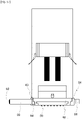
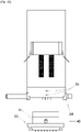
- a discharge device 1 according to a first embodiment of the present invention will be described below with reference to Figs. 1 and 2 .
- the side directing towards an observer from the drawing sheet of Fig. 1 i.e., the left side in Fig. 2
- the side directing away from the observer from the drawing sheet of Fig. 1 i.e., the right side in Fig. 2
- the "rear" in some cases.
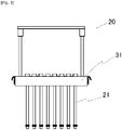
- the discharge device 1 includes, as main components, a plunger unit 20, a valve unit 40, a plunger drive unit 60, and a valve drive unit 70.
- the plunger unit 20 includes eight plungers 21 that are operated to suck or push a liquid material.
- the eight plungers 21 are arranged at even intervals in a row direction and are fitted to a plunger holder 31.
- the plunger holder 31 is coupled to an elevating member 63, and the elevating member 63 is fixed at the backside to a slide base 62.
- the slide base 62 is coupled to a pair of slide rails (not illustrated) disposed on the rear side of a pair of openings 65 that are formed in a front surface of an uprightly-standing device main body 2, and the plungers 21 are moved up and down together with the slide base 62.
- the valve unit 40 switches over communication of flow paths between a mode of sucking the liquid material and a mode of discharging the liquid material such that the liquid material is sucked into the discharge device with retracting movement of each plunger, and that the liquid material is discharged with advancing movement of each plunger.
- the plunger drive unit 60 includes a drive source, such as a motor or an actuator, for operating the plunger unit 20.
- the valve drive unit 70 includes a drive source, such as a motor or an actuator, for operating the valve unit 40.
- the plunger unit 20 includes the plurality of plungers 21 and the plunger holder 31.
- the plungers 21 are inserted into a plurality of metering bores 42 in a one-to-one relation such that each plunger sucks the liquid material into the metering bore with the retracting movement, and that each plunger discharges the liquid material in the metering bore with the advancing movement.
- the plunger holder 31 holds the specified number of plungers 21 at a predetermined interval therebetween.
- plural types of plunger units 20 are prepared. In other words, it is preferable to prepare plural types of plunger units 20 including the plungers 21 at different pitches and/or in different numbers.
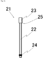
- the plungers 21 are each constituted by a plunger rod 22 having a plunger tail 23 at its backward end.
- the plunger rod 22 is an elongate columnar member
- the plunger tail 23 is a columnar member having a larger diameter than the plunger rod 22.
- An annular seal 24 is fitted over a distal end portion of the plunger rod 22.
- the seal 24 is not needed to be fitted when a lateral surface of the plunger rod 22 generates a sealing effect in cooperation with an inner wall of a metering member 41, the inner wall defining the metering bore 42.
- the seal 24 is preferably fitted in order to increase accuracy of an amount of the discharged liquid material. The reason is that sliding of the seal 24 in close contact with the inner wall of the metering member 41 prevents the liquid material from leaking through an opening 43 at a top of the metering bore and contributes to increasing the accuracy of the amount of the discharged liquid material.
- two posts 32 are fixed to the plunger holder 31 at positions near both side ends thereof. Respective upper ends of the two posts 32 are coupled to each other by a grip 33. Engagement pawls 34 used for attaching the plunger holder 31 to the elevating member 63 are disposed on both lateral surfaces of the plunger holder 31.
- the engagement pawls 34 are, e.g., pawls of a Draw Latch and are engaged with a pair of locking attachments 64, i.e., Draw Latch bodies, which are disposed on both lateral surfaces of the elevating member 63. It is needless to say that the Draw Latch is merely one example, and that the plunger holder 31 and the elevating member 63 may be fixedly coupled to each other by employing any of other suitable detachable connection means.
- plunger insertion bores (36, 37) are formed to extend in a vertical direction in number equal to or larger than the number of the plungers 21 to be held.
- the plunger insertion bores are each constituted by a small-diameter bore 36 positioned on the lower side and a large-diameter hole 37 positioned on the upper side.
- the large-diameter hole 37 has substantially the same diameter as that of the plunger tail 23, and a shoulder 25 of the plunger tail 23 abuts against the bottom of the large-diameter hole 37.
- the plungers 21 are fixed by engaging the locking attachments 64 on the elevating member 63 with the engagement pawls 34 on the lateral surfaces of the plunger holder 31, and by sandwiching the plunger tail 23 of each plunger between a step, formed at a boundary between the large-diameter hole 37 and the small-diameter bore 36, and a lower surface of the elevating member 63.
- the small-diameter bore 36 is formed in a diameter larger than that of the plunger rod 22.
- the small-diameter bore 36 is formed in a diameter larger than that of the seal 24.
- the shoulder 25 of the plunger tail 23 may be abutted against the upper surface of the plunger holder 31 from above.
- the small-diameter bore 36 having a smaller diameter than the plunger tail 23 is formed to penetrate through the plunger holder 31, and the plunger 21 is fixed by inserting the plunger rod 22 into the small-diameter bore 36 from the upper side, and by abutting the shoulder 25 of the plunger tail 23 against the upper surface of the plunger holder 31.
- Fig. 6(a) is a front view of a modification of the plunger holder 31, and Fig. 6(b) is a plan view of the modification.
- the plunger holder 31 illustrated in Fig. 6 includes guide grooves 35 in number equal to or larger than the number of the plungers 21 to be held.
- the guide grooves 35 are opened at a lateral surface of the plunger holder 31 on the front side.
- In an innermost portion of each of the guide grooves 35 there are formed a small-diameter bore 36 positioned on the lower side, and a large-diameter hole 37 positioned on the upper side.
- the guide groove 35 has a width slightly larger than the diameter of the plunger rod 22. It is to be noted that the width of the guide groove 35 is not needed to be larger than the diameter of the seal 24.
- the small-diameter bore 36 has a diameter equal to the width of the guide groove 35, and the innermost portion of the guide groove 35 substantially constitutes the small-diameter bore 36.
- Fig. 7 is a side view illustrating a state where the plungers 21 are fitted to the plunger holder 31 illustrated in Fig. 6 .
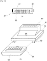
- Fig. 8 is a perspective view referenced to explain a structure of the valve unit 40.
- the valve unit 40 includes, as main components, a metering member 41, a holding member 48, and a valve member 50.
- the metering member 41 includes metering bores 42 in number equal to or larger than the number of the plungers 21. All the metering bores 42 have the same length.
- valve units 40 are prepared to be capable of accepting plural types of plunger units 20.
- a plurality of valve units 40 are provided including the metering bores 42 formed at different pitches and/or in different numbers.
- the metering bores 42 are each a through-bore penetrating the metering member 41 and the holding member 48. Each metering bore 42 has a metering-bore upper opening 43 opened at an upper surface of the metering member 41, and a metering-bore lower opening 44 opened at a lower surface of the holding member 48.
- a center-to-center pitch of the metering bores 42 is the same as that of the small-diameter bores 36 formed in the plunger holder 31. In other words, an interval between the metering bores 42 is the same as that between the plungers 21 fitted to the plunger holder 31.
- a desired amount of the liquid material is sucked into each of the metering bores 42 with retracting movement of the plunger 21 that is inserted into the metering bore 42 from the metering-bore upper opening 43.
- the metering bore 42 sucks or ejects the liquid material in cooperation with the plunger 21 moved to retract or advance.
- One liquid material supply path 45 is formed in the metering member 41 and the holding member 48.
- the liquid material supply path 45 is a through-bore penetrating the metering member 41 and the holding member 48.
- the liquid material supply path 45 has a supply path inlet 46 opened at the upper surface of the metering member 41, and a supply path outlet 47 opened at the lower surface of the holding member 48.
- the holding member 48 in the form of a plate is disposed under the metering member 41.
- the metering member 41 and the holding member 48 may be fabricated separately and coupled to each other, or may be fabricated in an integral form.
- the holding member 48 has a pair of holding portions 49 provided on its lower surface at the right and left sides in a symmetrical relation.
- the holding portions 49 have L-shaped cross-sections in a widthwise direction, and lateral projections 59 formed at both lateral surfaces of the valve member 50 are allowed to slide into grooves defined by the L-shaped holding portions 49, respectively.
- the valve member 50 is slidably held by the holding member 48 in a state where the lateral projections 59 are inserted respectively into the pair of holding portions 49 that are provided at the lower surface of the holding member 48.
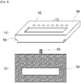
- Fig. 9(a) is a perspective view of the valve member 50
- Fig. 9(b) is a horizontal sectional view of the valve member 50.
- the valve member 50 includes a plurality of discharge paths 51 opened at its upper surface on the rear side, and a recess 55 formed in its upper surface on the front side.
- the discharge paths 51 are each a through-bore extending from the upper surface to a lower surface of the valve member 50.
- the discharge path 51 has a discharge path inlet 52 opened at the upper surface of the valve member 50, and a discharge port 53 opened at the lower surface of the valve member 50.
- a lower portion of the discharge path 51 is tapered with a flow path diameter gradually decreasing downwards, and a nozzle 54 having the discharge port 53 is formed at a lower end of the discharge path 51.
- plural types of valve members 50 having the discharge ports 53 with different diameters are prepared to be adaptable for a variety of uses. Replacement of the valve member 50 is easy because the valve member 50 can be attached and detached just by sliding the valve member 50 to move into and out from the metering member 41.
- a center-to-center pitch of the discharge paths 51 formed in the same number as the metering bores 42 is the same as that of the metering bores 42.
- the center-to-center pitch of the small-diameter bores 36 formed in the plunger holder 31, the center-to-center pitch of the metering bores 42, and the center-to-center pitch of the discharge paths 51 are all the same.
- the recess 55 is a rectangular recess that is formed by cutting the valve member 50 from its upper surface.
- the recess 55 constitutes, as described later, a supply flow path for communicating the liquid material supply path 45 with all the metering bores 42.
- the shape of the recess 55 is not limited to the illustrated rectangular shape, and the recess 55 may have any one of substantially triangular, trapezoidal, pentagonal, elliptical, and other suitable shapes in a plan view. Alternatively, the recess 55 may be formed as branched paths. A width of the recess 55 in a right-left direction is larger than the length of a line interconnecting outermost extensions of the discharge paths 51 that are positioned at the right and left ends.
- a rear projection 58 having a width smaller than that of the rear surface of the valve member 50 in the right-left direction.
- the rear projection 58 is a member having a rectangular parallelepiped shape, and a connector 72 of the valve drive unit 70 is coupled to the rear projection 58.
- the valve drive unit 70 operates the connector 72 to horizontally advance and retract in a reciprocating manner, the valve member 50 is also horizontally moved in a reciprocating manner relative to the metering member 41.
- the valve member 50 takes a first position at which the liquid material supply path 45 is communicated with the metering bores 42, and a second position at which the metering bores 42 in the metering member 41 are communicated with the discharge paths 51 in the valve member 50.
- the valve member 50 takes the first position, the recess 55 is positioned to cover an area involving not only the supply path outlet 47, but also all the metering-bore lower openings 44, and the supply path outlet 47 is communicated with all the metering bores 42 (see Figs. 11(a) and 11(c) ).
- the valve member 50 takes the second position, all the metering bores 42 are communicated with the discharge ports 53 through the discharge paths 51, respectively.
- Fig. 10(a) is a perspective view referenced to explain a modification of the valve member 50
- Fig. 10(b) is a horizontal sectional view of the modification.
- an annular leakage preventive groove 56 is formed so as to surround all the discharge paths 51 and the recess 55. Accordingly, even if the liquid material leaks from the discharge paths 51 or the recess 55, the liquid material having leaked is caught in the leakage preventive groove 56.
- valve member 50 may be constituted by two plate-like members stacked one above the other.
- the lower plate-like member (nozzle member) having the discharge ports 53 is not horizontally moved, and only the upper plate-like member (valve member) is moved while sliding in contact with both the metering member 41 and the lower plate-like member (nozzle member).
- the above structure has an advantage that, because the discharge ports 53 are not horizontally moved, the problem of, e.g., liquid dripping from the discharge ports 53 is less likely to occur.
- the plunger drive unit 60 includes a driver A 61, a slide base 62, and an elevating member 63.
- the driver A 61 is a motor, for example, and it serves as a drive source for moving the slide base 62 to reciprocate in an extending direction of the metering bores 42.
- the elevating member 63 is connected to the slide base 62.
- the slide base 62 is movable along a pair of elongate openings 65 that extend in the vertical direction.
- the locking attachments 64 engageable with the engagement pawls 34 on the plunger holder 31 are disposed on right and left lateral surfaces of the elevating member 63.
- the plunger holder 31 and the elevating member 63 can be detachably coupled and fixed by engaging the locking attachments 64 on the elevating member 63 with the engagement pawls 34 on the lateral surfaces of the plunger holder 31.
- the valve drive unit 70 includes an arm 71, a connector 72, and a driver 73.
- the connector 72 is coupled to one end of the arm 71, and the driver 73 is coupled to the other end of the arm 71.
- the rear projection 58 of the valve member 50 and the arm 71 are detachably coupled and fixed through the connector 72. Therefore, movement of the arm 71 operated by the driver 73 is transmitted to the valve member 50 through the connector 72, and the valve member 50 is moved to slide in a reciprocating manner relative to the metering member 41.
- the driver 73 is an actuator, for example, and it moves the arm 71 extending in the horizontal direction to advance or retract relative to the valve unit 40.
- the valve unit 40 takes the first position at which the liquid material supply path 45 and the metering bores 42 are communicated with each other.
- the valve unit 40 takes the second position at which the metering bores 42 and the discharge ports 53 are communicated with each other.
- the valve drive unit 70 performs a valve switching operation of the valve unit 40 as described above.
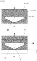
- Fig. 11(a) illustrates a state where the valve unit 40 takes the first position and the plunger 21 is present at a lowermost position. At the first position, the metering bore 42 is communicated with the liquid material supply path 45 through the recess 55, while the metering bore 42 is disconnected from the discharge port 53. In Fig. 11(a) , the discharge path 51 is filled with the liquid material, but it is not communicated with the metering bore 42.
- Fig. 11(b) illustrates a state where the valve unit 40 takes the first position and the plunger 21 is present at an upper position.
- Fig. 11(b) illustrates a state where the plunger 21 is moved upwards from the state of Fig. 11(a) and the liquid material is supplied to the metering bore 42.
- the upper position of the plunger 21 is variable, and an amount of the liquid material sucked into the metering bore 42 can be adjusted by controlling the driver A 61 and by adjusting a distance through which the plunger 21 is moved upwards. Thus, a desired amount of the liquid material can be sucked into the metering bore 42.
- Fig. 11(c) illustrates a state where the valve unit 40 takes the second position and the plunger 21 is present at the upper position. More specifically, the valve member 50 is moved to advance from the state of Fig. 11(b) , whereupon the metering bore 42 is disconnected from the liquid material supply path 45 and the metering bore 42 is communicated with the discharge port 53. The plunger 21 is held at the same position (height) as that illustrated in Fig. 11(b) .
- Fig. 11(d) illustrates a state where the valve unit 40 takes the second position and the plunger 21 is present at the lowermost position.
- Fig. 11(d) illustrates a state where the plunger 21 is moved downwards from the state of Fig. 11(c) and the liquid material in the metering bore 42 is discharged.
- the plunger 21 is moved to the lowermost end and the liquid material in the metering bore 42 is all discharged, the liquid material may be discharged by repeating the downward movement of the plunger 21 while the plunger 21 is stopped once or several times just before reaching the lowermost end of the metering bore 42.
- the liquid material in the metering bore 42 can also be discharged in the form of plural divided droplets by controlling the driver A so as to intermittently move the plunger 21 downwards.
- An amount of the liquid material discharged once from one discharge port 53 is on the order of ng to mg, for example.
- valve member 50 is restored from the state of Fig. 11(d) after the end of the discharge operation to the state of Fig. 11(a) with the operation of the driver 73 moving the valve member 50 to retract.
- the droplets can be repeatedly discharged by successively repeating the states of Figs. 11(a) to 11(d) .
- the liquid material supply path 45 is always communicated with a liquid supply source (not illustrated), and the liquid material supply path 45 and the recess 55 are always kept in a state filled with the liquid material.
- Fig. 12(a) is a horizontal sectional view referenced to explain a state where the valve member 50 is present at the second position
- Fig. 12(b) is a horizontal sectional view referenced to explain a state where the valve member 50 is present at the first position.
- the discharge paths 51 and the metering bores 42 are communicated with each other, the liquid material in the metering bores 42 can be discharged.
- Fig. 12(a) at the second position, since the discharge paths 51 and the metering bores 42 are communicated with each other, the liquid material in the metering bores 42 can be discharged.
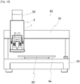
- Fig. 13 is a front view of an application device 90 equipped with the discharge device 1.
- the application device 90 includes an X-direction moving device 91 capable of moving the discharge device 1 in an X-direction, a Y-direction moving device 92 capable of moving a table 94 in a Y-direction, a Z-direction moving device 93 holding the device main body 2, and a pedestal 95 on which the table 94 is mounted.
- the XYZ-direction moving devices (91, 92 and 93) are each constituted, for example, by a combination of an electric motor and a ball screw, a mechanism using a linear motor, or a mechanism for transmitting motive power through a belt, a chain, etc.
- a work is placed on the table 94, and an applying operation is performed while the discharge device 1 and the table 94 are moved relatively to each other in the XYZ-directions.
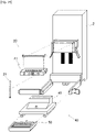
- the components of the discharge device 1 can be disassembled easily.
- Fig. 14 is a perspective view of the discharge device 1 in a disassembled state.
- the plunger unit 20 and the valve unit 40 can be detached from the device main body.
- the plunger unit 20 can be disassembled into the plunger holder 31 and the plungers 21, and the valve unit 40 can be disassembled into the metering member 41 and the valve member 50.
- Fig. 14 illustrates the plunger holder 31 of the type illustrated in Fig. 6 and the valve member 50 of the type illustrated in Fig. 10 .
- Fig. 15 is a front view of the discharge device 1, the view illustrating a state where the engagement pawls 34 on the lateral surfaces of the plunger holder 31 are disengaged from the locking attachments 64 on the elevating member 63, and Fig.
- FIG. 16 is a front view of the discharge device 1, the view illustrating a state where the plunger unit 20 is detached from the elevating member 63.
- the Draw Latch (34, 64) disclosed here, by way of example, is convenient in use because it can be latched and unlatched without needing a special tool, e.g., a driver or a wrench.
- the valve unit 40 is detached by unlocking a locking attachment 81 from a state engaged with a pawl 82, the locking attachment 81 and the pawl 82 being disposed on a valve unit cover 80.
- the valve unit cover 80 serves as a locking member to fix a position of the valve unit 40.
- An end portion of the valve unit cover 80 on the side opposite to the pawl 82 is fixedly held by a hinge 83 to be rotatable.
- the valve unit 40 is supported by a valve unit support mechanism in a withdrawable manner.
- valve unit 40 is supported in a withdrawable manner in such a state where a valve unit support 84 supports the lateral projections 59 of the holding member 48 and pins 85 are inserted through holes that are formed in a rear surface of the metering member 41.
- the valve unit 40 can be detached by rotating the valve unit cover 80 to be opened, and by withdrawing the metering member 41 and the valve member 50.
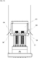
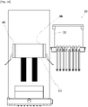
- Fig. 17 is a front view of the discharge device 1 in a state where the valve unit cover 80 is opened
- Fig. 18 is a front view of the discharge device 1 in a state where the valve unit 40 is detached from the elevating member 63.
- the components of the discharge device 1 can be easily disassembled, maintenance operations, such as cleaning, exchange of the liquid material, change of the application conditions, change of the pitch, replacement, and detachment.
- the number of discharge ports and the interval therebetween can be changed by preparing plural types of plunger units 20 and plural types of valve units 40, and by replacing them depending on uses.
- a discharge device 1 according to a second embodiment is different from the discharge device according to the first embodiment in including sixteen plungers 21, while the other structure is common to both the first and second embodiments.
- different points from the first embodiment are mainly described, and description of the structure common to the first embodiment is omitted.
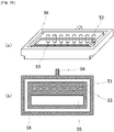
- Fig. 19(a) illustrates a plunger holder 31 according to the second embodiment
- Fig. 19(b) is an exploded perspective view of a valve unit 40 according to the second embodiment.
- Fig. 19(a) sixteen (2 rows ⁇ 8 columns) large-diameter holes 37 are formed in the plunger holder 31.
- the large-diameter holes 37 are each constituted similarly to that illustrated in Figs. 5 and 6 .
- the shoulder 25 of the plunger tail 23 is abutted against the bottom of the large-diameter hole 37.
- the width of a guide groove 35 is slightly larger than the diameter of the plunger rod 22.
- the eight guide grooves 35 are disposed at the same pitch.
- the sixteen large-diameter holes 37 are disposed at the same pitch in each of the row direction and the column direction.
- sixteen metering bores 42 are formed in the metering member 41, and sixteen discharge paths 51 are formed in the valve member 50.
- the metering bores 42, the discharge paths 51, and the large-diameter holes 37 have the same center-to- center pitch.
- the valve unit 40 takes the above-described first position and second position.
- the recess 55 is positioned to cover an area involving not only the supply path outlet 47, but also all the metering-bore lower openings 44, and the supply path outlet 47 is communicated with all the metering bores 42.
- the valve unit 40 takes the second position, all the metering bores 42 are communicated with the discharge ports 53 through the discharge paths 51, respectively.
- a number (n ⁇ m) of plungers 21 (where n and m are each an integer equal to or more than 1 and n ⁇ m is 3 or more) can be mounted to the discharge device 1.
- Optimum mounting of the plungers can be realized depending on uses by preparing the plunger units 20 including the plungers in different numbers and/or at different pitches and the valve units 40 corresponding to those plunger units.
- a discharge device 1 according to a third embodiment is different from the discharge device according to the first embodiment in that the recess 55 formed in the metering member 41 has a substantially pentagonal shape, while the other structure is common to both the first and third embodiments.
- a different point from the first embodiment is mainly described, and description of the structure common to the first embodiment is omitted.
- Fig. 20 illustrates a valve member 41 in the third embodiment; specifically, Fig. 20(a) is a horizontal sectional view referenced to explain a state where the valve member is present at the second position, and Fig. 20(b) is a horizontal sectional view referenced to explain a state where the valve member is present at the first position.
- the object of the present invention can be achieved.
- the recess 55 having the substantially pentagonal shape the amount of the liquid material held in the recess 55 can be reduced in comparison with that in the first embodiment.
- a discharge device 1 according to a third embodiment is different from the discharge device according to the first embodiment in that the recess 55 formed in the metering member 41 has a shape of a branched path, while the other structure is common to both the first and fourth embodiments.
- a different point from the first embodiment is mainly described, and description of the structure common to the first embodiment is omitted.
- Fig. 21 illustrates a valve member 41 in a fourth embodiment; specifically, Fig. 21(a) is a horizontal sectional view referenced to explain a state where the valve member is present at the second position, and Fig. 21(b) is a horizontal sectional view referenced to explain a state where the valve member is present at the first position.
- the object of the present invention can be achieved.
- the recess 55 being constituted by the branched path, the amount of the liquid material held in the recess 55 can be reduced in comparison with that in the third embodiment.
Landscapes
- Coating Apparatus (AREA)
- Application Of Or Painting With Fluid Materials (AREA)
Applications Claiming Priority (2)
| Application Number | Priority Date | Filing Date | Title |
|---|---|---|---|
| JP2013204578A JP6364168B2 (ja) | 2013-09-30 | 2013-09-30 | 液体材料吐出装置および塗布方法 |
| PCT/JP2014/075789 WO2015046481A1 (ja) | 2013-09-30 | 2014-09-29 | 液滴材料吐出装置、同液体材料吐出装置を備える塗布装置および同塗布装置を用いた塗布方法 |
Publications (3)
| Publication Number | Publication Date |
|---|---|
| EP3053659A1 EP3053659A1 (en) | 2016-08-10 |
| EP3053659A4 EP3053659A4 (en) | 2017-07-26 |
| EP3053659B1 true EP3053659B1 (en) | 2022-11-02 |
Family
ID=52743605
Family Applications (1)
| Application Number | Title | Priority Date | Filing Date |
|---|---|---|---|
| EP14849745.6A Active EP3053659B1 (en) | 2013-09-30 | 2014-09-29 | Liquid material discharge device, application device provided with same liquid material discharge device, and coating method using same application device |
Country Status (7)
| Country | Link |
|---|---|
| US (1) | US10843220B2 (enExample) |
| EP (1) | EP3053659B1 (enExample) |
| JP (1) | JP6364168B2 (enExample) |
| KR (1) | KR102328958B1 (enExample) |
| CN (1) | CN105592936B (enExample) |
| TW (1) | TWI644733B (enExample) |
| WO (1) | WO2015046481A1 (enExample) |
Families Citing this family (8)
| Publication number | Priority date | Publication date | Assignee | Title |
|---|---|---|---|---|
| JP6646809B2 (ja) * | 2016-01-18 | 2020-02-14 | パナソニックIpマネジメント株式会社 | 液体吐出用の吐出ノズル |
| JP6739786B2 (ja) | 2016-05-30 | 2020-08-12 | 武蔵エンジニアリング株式会社 | 液体材料吐出装置、その塗布装置および塗布方法 |
| JP6842152B2 (ja) | 2016-05-31 | 2021-03-17 | 武蔵エンジニアリング株式会社 | 液体材料吐出装置、その塗布装置および塗布方法 |
| JP6778426B2 (ja) * | 2016-09-20 | 2020-11-04 | 武蔵エンジニアリング株式会社 | 液体材料吐出装置 |
| CN112570201A (zh) * | 2019-09-29 | 2021-03-30 | 深圳市向宇龙自动化设备有限公司 | 一种多通道多孔径的点胶装置 |
| JP7066229B2 (ja) * | 2021-01-06 | 2022-05-13 | 武蔵エンジニアリング株式会社 | 液体材料吐出装置、その塗布装置および塗布方法 |
| CN115475724A (zh) * | 2021-06-16 | 2022-12-16 | 盟立自动化股份有限公司 | 湿式涂布设备及涂布装置 |
| CN115475736B (zh) * | 2021-06-16 | 2024-11-12 | 盟立自动化股份有限公司 | 供料装置 |
Family Cites Families (31)
| Publication number | Priority date | Publication date | Assignee | Title |
|---|---|---|---|---|
| US2296079A (en) * | 1939-01-23 | 1942-09-15 | Gen Mills Inc | Gluing head |
| US3213587A (en) * | 1962-07-23 | 1965-10-26 | Eben H Carruthers | Method for packing compressible materials into containers |
| US3557820A (en) * | 1968-08-28 | 1971-01-26 | Butler Manufacturing Co | Liquid distribution apparatus |
| JPS63171665A (ja) * | 1987-01-09 | 1988-07-15 | Alps Electric Co Ltd | 樹脂吐出装置 |
| DE4142940C2 (de) * | 1991-12-24 | 1994-01-27 | Bosch Gmbh Robert | Elektrisch gesteuerte Pumpedüse |
| JP3159504B2 (ja) * | 1992-02-20 | 2001-04-23 | 松下電器産業株式会社 | 液晶パネルの製造方法 |
| US6245189B1 (en) * | 1994-12-05 | 2001-06-12 | Nordson Corporation | High Throughput plasma treatment system |
| US5632448A (en) * | 1995-01-25 | 1997-05-27 | Ransburg Corporation | Rotary powder applicator |
| JPH09220507A (ja) * | 1996-02-15 | 1997-08-26 | Akebono Brake Ind Co Ltd | 粘性材供給装置 |
| IT1304779B1 (it) * | 1998-12-03 | 2001-03-29 | Ima Spa | Dosatrice a disco ed a pestelli, a funzionamento intermittente,monogiostra, particolarmente adatta per il confezionamento di dosi |
| DE10001068C1 (de) * | 2000-01-13 | 2001-05-31 | Bosch Gmbh Robert | Vorrichtung zum Dosieren und Abgeben von Pulver in Hartgelatinekapseln oder dergleichen |
| ITBO20010082A1 (it) * | 2001-02-15 | 2002-08-16 | Ima Spa | Macchina comprimitrice per la produzione di compresse |
| JP2002258299A (ja) * | 2001-02-28 | 2002-09-11 | Matsushita Electric Ind Co Ltd | 液晶表示装置の製造方法および製造装置ならびに液晶表示装置 |
| JP2002361529A (ja) * | 2001-06-07 | 2002-12-18 | Koganei Corp | スライドテーブル往復動装置 |
| US7102726B2 (en) * | 2002-03-15 | 2006-09-05 | Lg. Philips Lcd Co., Ltd. | System for fabricating liquid crystal display and method of fabricating liquid crystal display using the same |
| ITBO20020284A1 (it) * | 2002-05-14 | 2003-11-14 | Ima Spa | Macchina opercolatrice |
| JP3543813B2 (ja) * | 2002-07-31 | 2004-07-21 | セイコーエプソン株式会社 | 液滴吐出方法及び液滴吐出装置、液晶装置の製造方法及び液晶装置、並びに電子機器 |
| JP4282056B2 (ja) * | 2002-11-08 | 2009-06-17 | 武蔵エンジニアリング株式会社 | 液体材料の吐出装置 |
| FI113527B (fi) * | 2002-12-31 | 2004-05-14 | Raute Oyj | Suutinyksikkö |
| KR100939629B1 (ko) * | 2003-06-02 | 2010-01-29 | 엘지디스플레이 주식회사 | 액정 표시패널의 실린지 |
| ITBO20040310A1 (it) * | 2004-05-18 | 2004-08-18 | Ima Spa | Macchina opercolatrice e relativo metodo per la produzione di capsule in gelatina dura. |
| US20060029724A1 (en) * | 2004-08-06 | 2006-02-09 | Nordson Corporation | System for jetting phosphor for optical displays |
| JP2006084975A (ja) | 2004-09-17 | 2006-03-30 | Fujitsu Display Technologies Corp | 液晶表示装置の製造方法及び液晶滴下装置 |
| WO2007046495A1 (ja) * | 2005-10-21 | 2007-04-26 | Musashi Engineering, Inc. | 液材吐出装置 |
| JP4969461B2 (ja) * | 2006-01-12 | 2012-07-04 | 武蔵エンジニアリング株式会社 | 液材吐出装置 |
| DE102006014496A1 (de) * | 2006-03-29 | 2007-10-04 | Robert Bosch Gmbh | Vorrichtung zum Befüllen von zumindest einer Dosierkammer |
| ITMO20060197A1 (it) * | 2006-06-16 | 2007-12-17 | Kemac S P A | Iniettore per fluidi viscosi |
| JP5089969B2 (ja) * | 2006-12-04 | 2012-12-05 | 武蔵エンジニアリング株式会社 | 液体材料吐出装置 |
| CN102006943B (zh) * | 2008-02-21 | 2013-07-24 | 武藏工业株式会社 | 液体材料的排出装置及其涂布装置 |
| JP2009220507A (ja) * | 2008-03-18 | 2009-10-01 | Seiko Epson Corp | 液体噴射ヘッドの製造方法 |
| JP5271972B2 (ja) * | 2010-06-21 | 2013-08-21 | ルネサスエレクトロニクス株式会社 | 半導体装置の製造方法および半導体製造装置 |
-
2013
- 2013-09-30 JP JP2013204578A patent/JP6364168B2/ja active Active
-
2014
- 2014-09-29 US US15/025,373 patent/US10843220B2/en active Active
- 2014-09-29 EP EP14849745.6A patent/EP3053659B1/en active Active
- 2014-09-29 WO PCT/JP2014/075789 patent/WO2015046481A1/ja not_active Ceased
- 2014-09-29 CN CN201480054028.1A patent/CN105592936B/zh active Active
- 2014-09-29 KR KR1020167008594A patent/KR102328958B1/ko active Active
- 2014-09-30 TW TW103133884A patent/TWI644733B/zh active
Also Published As
| Publication number | Publication date |
|---|---|
| CN105592936A (zh) | 2016-05-18 |
| CN105592936B (zh) | 2018-12-11 |
| KR20160064117A (ko) | 2016-06-07 |
| HK1221192A1 (zh) | 2017-05-26 |
| JP2015066522A (ja) | 2015-04-13 |
| EP3053659A4 (en) | 2017-07-26 |
| EP3053659A1 (en) | 2016-08-10 |
| TWI644733B (zh) | 2018-12-21 |
| WO2015046481A1 (ja) | 2015-04-02 |
| US20160236228A1 (en) | 2016-08-18 |
| TW201529175A (zh) | 2015-08-01 |
| US10843220B2 (en) | 2020-11-24 |
| KR102328958B1 (ko) | 2021-11-18 |
| JP6364168B2 (ja) | 2018-07-25 |
Similar Documents
| Publication | Publication Date | Title |
|---|---|---|
| EP3053659B1 (en) | Liquid material discharge device, application device provided with same liquid material discharge device, and coating method using same application device | |
| US8697012B2 (en) | High-speed automatic dispensing device with replaceable dispensing head and dispensing station | |
| US5932065A (en) | Universal fixture for supporting and holding populated sides of printed circuit board assemblies during processing | |
| KR101534118B1 (ko) | 액체 재료의 토출 장치, 및 그 도포 장치 및 도포 방법 | |
| US8136652B2 (en) | Processing station for a processing line having a module platform and withdrawable modules that can be introduced into the module platform | |
| JP2015066522A5 (enExample) | ||
| US10117368B2 (en) | Board work device | |
| US20040146383A1 (en) | Apparatus having a variable pitch pick-and-place head for packaging electrical parts and methods of operating the same | |
| CN215542411U (zh) | 适用于点胶机的拨线设备 | |
| TW201511840A (zh) | 塗布裝置 | |
| KR102328887B1 (ko) | 액체 재료 적하 장치 및 방법 | |
| JP4196923B2 (ja) | 液体分注ヘッド装置及び液体分注装置 | |
| KR101415609B1 (ko) | 개선된 멀티 헤드 및 그 제조 방법, 및 이를 구비한 스프레이 방식의 패턴 형성 장치 및 그 제조 방법 | |
| JP4235599B2 (ja) | 液体分注ヘッド装置及び液体分注装置 | |
| HK1221192B (zh) | 液体材料吐出装置、具备该液体材料吐出装置的涂布装置及使用该涂布装置的涂布方法 | |
| JP5919575B2 (ja) | ノズル型検査洗浄装置 | |
| JP2005030769A (ja) | 液体吸引装置および液体吐出装置 | |
| KR200384714Y1 (ko) | 인서트부재 정렬 시스템 | |
| CN115723069A (zh) | 一种独立双推定位结构 | |
| CN112517336A (zh) | 推拉式多针点胶阀及其点胶方法 | |
| HK1112642B (en) | High-speed automatic dispensing device with replaceable dispensing head and dispensing station |
Legal Events
| Date | Code | Title | Description |
|---|---|---|---|
| PUAI | Public reference made under article 153(3) epc to a published international application that has entered the european phase |
Free format text: ORIGINAL CODE: 0009012 |
|
| 17P | Request for examination filed |
Effective date: 20160425 |
|
| AK | Designated contracting states |
Kind code of ref document: A1 Designated state(s): AL AT BE BG CH CY CZ DE DK EE ES FI FR GB GR HR HU IE IS IT LI LT LU LV MC MK MT NL NO PL PT RO RS SE SI SK SM TR |
|
| AX | Request for extension of the european patent |
Extension state: BA ME |
|
| DAX | Request for extension of the european patent (deleted) | ||
| A4 | Supplementary search report drawn up and despatched |
Effective date: 20170623 |
|
| RIC1 | Information provided on ipc code assigned before grant |
Ipc: G02F 1/1341 20060101ALN20170619BHEP Ipc: B05D 1/26 20060101ALI20170619BHEP Ipc: B05C 5/02 20060101AFI20170619BHEP |
|
| STAA | Information on the status of an ep patent application or granted ep patent |
Free format text: STATUS: EXAMINATION IS IN PROGRESS |
|
| 17Q | First examination report despatched |
Effective date: 20200911 |
|
| RIC1 | Information provided on ipc code assigned before grant |
Ipc: G02F 1/1341 20060101ALN20220310BHEP Ipc: B05D 1/26 20060101ALI20220310BHEP Ipc: B05C 5/02 20060101AFI20220310BHEP |
|
| REG | Reference to a national code |
Ref country code: DE Ref legal event code: R079 Ref document number: 602014085430 Country of ref document: DE Free format text: PREVIOUS MAIN CLASS: B05C0005000000 Ipc: B05C0005020000 |
|
| GRAP | Despatch of communication of intention to grant a patent |
Free format text: ORIGINAL CODE: EPIDOSNIGR1 |
|
| STAA | Information on the status of an ep patent application or granted ep patent |
Free format text: STATUS: GRANT OF PATENT IS INTENDED |
|
| RIC1 | Information provided on ipc code assigned before grant |
Ipc: G02F 1/1341 20060101ALN20220414BHEP Ipc: B05D 1/26 20060101ALI20220414BHEP Ipc: B05C 5/02 20060101AFI20220414BHEP |
|
| INTG | Intention to grant announced |
Effective date: 20220516 |
|
| GRAS | Grant fee paid |
Free format text: ORIGINAL CODE: EPIDOSNIGR3 |
|
| GRAA | (expected) grant |
Free format text: ORIGINAL CODE: 0009210 |
|
| STAA | Information on the status of an ep patent application or granted ep patent |
Free format text: STATUS: THE PATENT HAS BEEN GRANTED |
|
| AK | Designated contracting states |
Kind code of ref document: B1 Designated state(s): AL AT BE BG CH CY CZ DE DK EE ES FI FR GB GR HR HU IE IS IT LI LT LU LV MC MK MT NL NO PL PT RO RS SE SI SK SM TR |
|
| REG | Reference to a national code |
Ref country code: GB Ref legal event code: FG4D |
|
| REG | Reference to a national code |
Ref country code: CH Ref legal event code: EP Ref country code: AT Ref legal event code: REF Ref document number: 1528366 Country of ref document: AT Kind code of ref document: T Effective date: 20221115 |
|
| REG | Reference to a national code |
Ref country code: DE Ref legal event code: R096 Ref document number: 602014085430 Country of ref document: DE |
|
| REG | Reference to a national code |
Ref country code: IE Ref legal event code: FG4D |
|
| REG | Reference to a national code |
Ref country code: LT Ref legal event code: MG9D |
|
| REG | Reference to a national code |
Ref country code: NL Ref legal event code: MP Effective date: 20221102 |
|
| REG | Reference to a national code |
Ref country code: AT Ref legal event code: MK05 Ref document number: 1528366 Country of ref document: AT Kind code of ref document: T Effective date: 20221102 |
|
| PG25 | Lapsed in a contracting state [announced via postgrant information from national office to epo] |
Ref country code: SE Free format text: LAPSE BECAUSE OF FAILURE TO SUBMIT A TRANSLATION OF THE DESCRIPTION OR TO PAY THE FEE WITHIN THE PRESCRIBED TIME-LIMIT Effective date: 20221102 Ref country code: PT Free format text: LAPSE BECAUSE OF FAILURE TO SUBMIT A TRANSLATION OF THE DESCRIPTION OR TO PAY THE FEE WITHIN THE PRESCRIBED TIME-LIMIT Effective date: 20230302 Ref country code: NO Free format text: LAPSE BECAUSE OF FAILURE TO SUBMIT A TRANSLATION OF THE DESCRIPTION OR TO PAY THE FEE WITHIN THE PRESCRIBED TIME-LIMIT Effective date: 20230202 Ref country code: LT Free format text: LAPSE BECAUSE OF FAILURE TO SUBMIT A TRANSLATION OF THE DESCRIPTION OR TO PAY THE FEE WITHIN THE PRESCRIBED TIME-LIMIT Effective date: 20221102 Ref country code: FI Free format text: LAPSE BECAUSE OF FAILURE TO SUBMIT A TRANSLATION OF THE DESCRIPTION OR TO PAY THE FEE WITHIN THE PRESCRIBED TIME-LIMIT Effective date: 20221102 Ref country code: ES Free format text: LAPSE BECAUSE OF FAILURE TO SUBMIT A TRANSLATION OF THE DESCRIPTION OR TO PAY THE FEE WITHIN THE PRESCRIBED TIME-LIMIT Effective date: 20221102 Ref country code: AT Free format text: LAPSE BECAUSE OF FAILURE TO SUBMIT A TRANSLATION OF THE DESCRIPTION OR TO PAY THE FEE WITHIN THE PRESCRIBED TIME-LIMIT Effective date: 20221102 |
|
| PG25 | Lapsed in a contracting state [announced via postgrant information from national office to epo] |
Ref country code: RS Free format text: LAPSE BECAUSE OF FAILURE TO SUBMIT A TRANSLATION OF THE DESCRIPTION OR TO PAY THE FEE WITHIN THE PRESCRIBED TIME-LIMIT Effective date: 20221102 Ref country code: PL Free format text: LAPSE BECAUSE OF FAILURE TO SUBMIT A TRANSLATION OF THE DESCRIPTION OR TO PAY THE FEE WITHIN THE PRESCRIBED TIME-LIMIT Effective date: 20221102 Ref country code: LV Free format text: LAPSE BECAUSE OF FAILURE TO SUBMIT A TRANSLATION OF THE DESCRIPTION OR TO PAY THE FEE WITHIN THE PRESCRIBED TIME-LIMIT Effective date: 20221102 Ref country code: IS Free format text: LAPSE BECAUSE OF FAILURE TO SUBMIT A TRANSLATION OF THE DESCRIPTION OR TO PAY THE FEE WITHIN THE PRESCRIBED TIME-LIMIT Effective date: 20230302 Ref country code: HR Free format text: LAPSE BECAUSE OF FAILURE TO SUBMIT A TRANSLATION OF THE DESCRIPTION OR TO PAY THE FEE WITHIN THE PRESCRIBED TIME-LIMIT Effective date: 20221102 Ref country code: GR Free format text: LAPSE BECAUSE OF FAILURE TO SUBMIT A TRANSLATION OF THE DESCRIPTION OR TO PAY THE FEE WITHIN THE PRESCRIBED TIME-LIMIT Effective date: 20230203 |
|
| P01 | Opt-out of the competence of the unified patent court (upc) registered |
Effective date: 20230519 |
|
| PG25 | Lapsed in a contracting state [announced via postgrant information from national office to epo] |
Ref country code: NL Free format text: LAPSE BECAUSE OF FAILURE TO SUBMIT A TRANSLATION OF THE DESCRIPTION OR TO PAY THE FEE WITHIN THE PRESCRIBED TIME-LIMIT Effective date: 20221102 |
|
| PG25 | Lapsed in a contracting state [announced via postgrant information from national office to epo] |
Ref country code: SM Free format text: LAPSE BECAUSE OF FAILURE TO SUBMIT A TRANSLATION OF THE DESCRIPTION OR TO PAY THE FEE WITHIN THE PRESCRIBED TIME-LIMIT Effective date: 20221102 Ref country code: RO Free format text: LAPSE BECAUSE OF FAILURE TO SUBMIT A TRANSLATION OF THE DESCRIPTION OR TO PAY THE FEE WITHIN THE PRESCRIBED TIME-LIMIT Effective date: 20221102 Ref country code: EE Free format text: LAPSE BECAUSE OF FAILURE TO SUBMIT A TRANSLATION OF THE DESCRIPTION OR TO PAY THE FEE WITHIN THE PRESCRIBED TIME-LIMIT Effective date: 20221102 Ref country code: DK Free format text: LAPSE BECAUSE OF FAILURE TO SUBMIT A TRANSLATION OF THE DESCRIPTION OR TO PAY THE FEE WITHIN THE PRESCRIBED TIME-LIMIT Effective date: 20221102 Ref country code: CZ Free format text: LAPSE BECAUSE OF FAILURE TO SUBMIT A TRANSLATION OF THE DESCRIPTION OR TO PAY THE FEE WITHIN THE PRESCRIBED TIME-LIMIT Effective date: 20221102 |
|
| REG | Reference to a national code |
Ref country code: DE Ref legal event code: R097 Ref document number: 602014085430 Country of ref document: DE |
|
| PG25 | Lapsed in a contracting state [announced via postgrant information from national office to epo] |
Ref country code: SK Free format text: LAPSE BECAUSE OF FAILURE TO SUBMIT A TRANSLATION OF THE DESCRIPTION OR TO PAY THE FEE WITHIN THE PRESCRIBED TIME-LIMIT Effective date: 20221102 Ref country code: AL Free format text: LAPSE BECAUSE OF FAILURE TO SUBMIT A TRANSLATION OF THE DESCRIPTION OR TO PAY THE FEE WITHIN THE PRESCRIBED TIME-LIMIT Effective date: 20221102 |
|
| PLBE | No opposition filed within time limit |
Free format text: ORIGINAL CODE: 0009261 |
|
| STAA | Information on the status of an ep patent application or granted ep patent |
Free format text: STATUS: NO OPPOSITION FILED WITHIN TIME LIMIT |
|
| 26N | No opposition filed |
Effective date: 20230803 |
|
| PG25 | Lapsed in a contracting state [announced via postgrant information from national office to epo] |
Ref country code: SI Free format text: LAPSE BECAUSE OF FAILURE TO SUBMIT A TRANSLATION OF THE DESCRIPTION OR TO PAY THE FEE WITHIN THE PRESCRIBED TIME-LIMIT Effective date: 20221102 |
|
| REG | Reference to a national code |
Ref country code: CH Ref legal event code: PL |
|
| PG25 | Lapsed in a contracting state [announced via postgrant information from national office to epo] |
Ref country code: LU Free format text: LAPSE BECAUSE OF NON-PAYMENT OF DUE FEES Effective date: 20230929 |
|
| REG | Reference to a national code |
Ref country code: BE Ref legal event code: MM Effective date: 20230930 |
|
| GBPC | Gb: european patent ceased through non-payment of renewal fee |
Effective date: 20230929 |
|
| PG25 | Lapsed in a contracting state [announced via postgrant information from national office to epo] |
Ref country code: LU Free format text: LAPSE BECAUSE OF NON-PAYMENT OF DUE FEES Effective date: 20230929 Ref country code: IT Free format text: LAPSE BECAUSE OF FAILURE TO SUBMIT A TRANSLATION OF THE DESCRIPTION OR TO PAY THE FEE WITHIN THE PRESCRIBED TIME-LIMIT Effective date: 20221102 Ref country code: MC Free format text: LAPSE BECAUSE OF FAILURE TO SUBMIT A TRANSLATION OF THE DESCRIPTION OR TO PAY THE FEE WITHIN THE PRESCRIBED TIME-LIMIT Effective date: 20221102 |
|
| REG | Reference to a national code |
Ref country code: IE Ref legal event code: MM4A |
|
| PG25 | Lapsed in a contracting state [announced via postgrant information from national office to epo] |
Ref country code: IE Free format text: LAPSE BECAUSE OF NON-PAYMENT OF DUE FEES Effective date: 20230929 |
|
| PG25 | Lapsed in a contracting state [announced via postgrant information from national office to epo] |
Ref country code: GB Free format text: LAPSE BECAUSE OF NON-PAYMENT OF DUE FEES Effective date: 20230929 |
|
| PG25 | Lapsed in a contracting state [announced via postgrant information from national office to epo] |
Ref country code: CH Free format text: LAPSE BECAUSE OF NON-PAYMENT OF DUE FEES Effective date: 20230930 |
|
| PG25 | Lapsed in a contracting state [announced via postgrant information from national office to epo] |
Ref country code: IE Free format text: LAPSE BECAUSE OF NON-PAYMENT OF DUE FEES Effective date: 20230929 Ref country code: GB Free format text: LAPSE BECAUSE OF NON-PAYMENT OF DUE FEES Effective date: 20230929 Ref country code: FR Free format text: LAPSE BECAUSE OF NON-PAYMENT OF DUE FEES Effective date: 20230930 Ref country code: CH Free format text: LAPSE BECAUSE OF NON-PAYMENT OF DUE FEES Effective date: 20230930 |
|
| PG25 | Lapsed in a contracting state [announced via postgrant information from national office to epo] |
Ref country code: BE Free format text: LAPSE BECAUSE OF NON-PAYMENT OF DUE FEES Effective date: 20230930 |
|
| PG25 | Lapsed in a contracting state [announced via postgrant information from national office to epo] |
Ref country code: BG Free format text: LAPSE BECAUSE OF FAILURE TO SUBMIT A TRANSLATION OF THE DESCRIPTION OR TO PAY THE FEE WITHIN THE PRESCRIBED TIME-LIMIT Effective date: 20221102 |
|
| PG25 | Lapsed in a contracting state [announced via postgrant information from national office to epo] |
Ref country code: BG Free format text: LAPSE BECAUSE OF FAILURE TO SUBMIT A TRANSLATION OF THE DESCRIPTION OR TO PAY THE FEE WITHIN THE PRESCRIBED TIME-LIMIT Effective date: 20221102 |
|
| PG25 | Lapsed in a contracting state [announced via postgrant information from national office to epo] |
Ref country code: CY Free format text: LAPSE BECAUSE OF FAILURE TO SUBMIT A TRANSLATION OF THE DESCRIPTION OR TO PAY THE FEE WITHIN THE PRESCRIBED TIME-LIMIT; INVALID AB INITIO Effective date: 20140929 |
|
| PG25 | Lapsed in a contracting state [announced via postgrant information from national office to epo] |
Ref country code: HU Free format text: LAPSE BECAUSE OF FAILURE TO SUBMIT A TRANSLATION OF THE DESCRIPTION OR TO PAY THE FEE WITHIN THE PRESCRIBED TIME-LIMIT; INVALID AB INITIO Effective date: 20140929 |
|
| PGFP | Annual fee paid to national office [announced via postgrant information from national office to epo] |
Ref country code: DE Payment date: 20250919 Year of fee payment: 12 |