EP3051608A1 - Batteriepack für elektrisches werkzeug - Google Patents
Batteriepack für elektrisches werkzeug Download PDFInfo
- Publication number
- EP3051608A1 EP3051608A1 EP16151797.4A EP16151797A EP3051608A1 EP 3051608 A1 EP3051608 A1 EP 3051608A1 EP 16151797 A EP16151797 A EP 16151797A EP 3051608 A1 EP3051608 A1 EP 3051608A1
- Authority
- EP
- European Patent Office
- Prior art keywords
- battery
- battery case
- battery pack
- outer shell
- rechargeable battery
- Prior art date
- Legal status (The legal status is an assumption and is not a legal conclusion. Google has not performed a legal analysis and makes no representation as to the accuracy of the status listed.)
- Granted
Links
Images

Classifications
-
- H—ELECTRICITY
- H01—ELECTRIC ELEMENTS
- H01M—PROCESSES OR MEANS, e.g. BATTERIES, FOR THE DIRECT CONVERSION OF CHEMICAL ENERGY INTO ELECTRICAL ENERGY
- H01M50/00—Constructional details or processes of manufacture of the non-active parts of electrochemical cells other than fuel cells, e.g. hybrid cells
- H01M50/30—Arrangements for facilitating escape of gases
-
- B—PERFORMING OPERATIONS; TRANSPORTING
- B25—HAND TOOLS; PORTABLE POWER-DRIVEN TOOLS; MANIPULATORS
- B25B—TOOLS OR BENCH DEVICES NOT OTHERWISE PROVIDED FOR, FOR FASTENING, CONNECTING, DISENGAGING, OR HOLDING
- B25B21/00—Portable power-driven screw or nut setting or loosening tools; Attachments for drilling apparatus serving the same purpose
-
- H—ELECTRICITY
- H01—ELECTRIC ELEMENTS
- H01M—PROCESSES OR MEANS, e.g. BATTERIES, FOR THE DIRECT CONVERSION OF CHEMICAL ENERGY INTO ELECTRICAL ENERGY
- H01M10/00—Secondary cells; Manufacture thereof
- H01M10/42—Methods or arrangements for servicing or maintenance of secondary cells or secondary half-cells
- H01M10/4207—Methods or arrangements for servicing or maintenance of secondary cells or secondary half-cells for several batteries or cells simultaneously or sequentially
-
- H—ELECTRICITY
- H01—ELECTRIC ELEMENTS
- H01M—PROCESSES OR MEANS, e.g. BATTERIES, FOR THE DIRECT CONVERSION OF CHEMICAL ENERGY INTO ELECTRICAL ENERGY
- H01M10/00—Secondary cells; Manufacture thereof
- H01M10/42—Methods or arrangements for servicing or maintenance of secondary cells or secondary half-cells
- H01M10/425—Structural combination with electronic components, e.g. electronic circuits integrated to the outside of the casing
-
- H—ELECTRICITY
- H01—ELECTRIC ELEMENTS
- H01M—PROCESSES OR MEANS, e.g. BATTERIES, FOR THE DIRECT CONVERSION OF CHEMICAL ENERGY INTO ELECTRICAL ENERGY
- H01M50/00—Constructional details or processes of manufacture of the non-active parts of electrochemical cells other than fuel cells, e.g. hybrid cells
- H01M50/20—Mountings; Secondary casings or frames; Racks, modules or packs; Suspension devices; Shock absorbers; Transport or carrying devices; Holders
- H01M50/204—Racks, modules or packs for multiple batteries or multiple cells
- H01M50/207—Racks, modules or packs for multiple batteries or multiple cells characterised by their shape
- H01M50/213—Racks, modules or packs for multiple batteries or multiple cells characterised by their shape adapted for cells having curved cross-section, e.g. round or elliptic
-
- H—ELECTRICITY
- H01—ELECTRIC ELEMENTS
- H01M—PROCESSES OR MEANS, e.g. BATTERIES, FOR THE DIRECT CONVERSION OF CHEMICAL ENERGY INTO ELECTRICAL ENERGY
- H01M50/00—Constructional details or processes of manufacture of the non-active parts of electrochemical cells other than fuel cells, e.g. hybrid cells
- H01M50/20—Mountings; Secondary casings or frames; Racks, modules or packs; Suspension devices; Shock absorbers; Transport or carrying devices; Holders
- H01M50/233—Mountings; Secondary casings or frames; Racks, modules or packs; Suspension devices; Shock absorbers; Transport or carrying devices; Holders characterised by physical properties of casings or racks, e.g. dimensions
- H01M50/24—Mountings; Secondary casings or frames; Racks, modules or packs; Suspension devices; Shock absorbers; Transport or carrying devices; Holders characterised by physical properties of casings or racks, e.g. dimensions adapted for protecting batteries from their environment, e.g. from corrosion
-
- H—ELECTRICITY
- H01—ELECTRIC ELEMENTS
- H01M—PROCESSES OR MEANS, e.g. BATTERIES, FOR THE DIRECT CONVERSION OF CHEMICAL ENERGY INTO ELECTRICAL ENERGY
- H01M50/00—Constructional details or processes of manufacture of the non-active parts of electrochemical cells other than fuel cells, e.g. hybrid cells
- H01M50/20—Mountings; Secondary casings or frames; Racks, modules or packs; Suspension devices; Shock absorbers; Transport or carrying devices; Holders
- H01M50/247—Mountings; Secondary casings or frames; Racks, modules or packs; Suspension devices; Shock absorbers; Transport or carrying devices; Holders specially adapted for portable devices, e.g. mobile phones, computers, hand tools or pacemakers
-
- H—ELECTRICITY
- H01—ELECTRIC ELEMENTS
- H01M—PROCESSES OR MEANS, e.g. BATTERIES, FOR THE DIRECT CONVERSION OF CHEMICAL ENERGY INTO ELECTRICAL ENERGY
- H01M50/00—Constructional details or processes of manufacture of the non-active parts of electrochemical cells other than fuel cells, e.g. hybrid cells
- H01M50/20—Mountings; Secondary casings or frames; Racks, modules or packs; Suspension devices; Shock absorbers; Transport or carrying devices; Holders
- H01M50/284—Mountings; Secondary casings or frames; Racks, modules or packs; Suspension devices; Shock absorbers; Transport or carrying devices; Holders with incorporated circuit boards, e.g. printed circuit boards [PCB]
-
- H—ELECTRICITY
- H01—ELECTRIC ELEMENTS
- H01M—PROCESSES OR MEANS, e.g. BATTERIES, FOR THE DIRECT CONVERSION OF CHEMICAL ENERGY INTO ELECTRICAL ENERGY
- H01M50/00—Constructional details or processes of manufacture of the non-active parts of electrochemical cells other than fuel cells, e.g. hybrid cells
- H01M50/20—Mountings; Secondary casings or frames; Racks, modules or packs; Suspension devices; Shock absorbers; Transport or carrying devices; Holders
- H01M50/296—Mountings; Secondary casings or frames; Racks, modules or packs; Suspension devices; Shock absorbers; Transport or carrying devices; Holders characterised by terminals of battery packs
-
- H—ELECTRICITY
- H01—ELECTRIC ELEMENTS
- H01M—PROCESSES OR MEANS, e.g. BATTERIES, FOR THE DIRECT CONVERSION OF CHEMICAL ENERGY INTO ELECTRICAL ENERGY
- H01M50/00—Constructional details or processes of manufacture of the non-active parts of electrochemical cells other than fuel cells, e.g. hybrid cells
- H01M50/30—Arrangements for facilitating escape of gases
- H01M50/342—Non-re-sealable arrangements
- H01M50/3425—Non-re-sealable arrangements in the form of rupturable membranes or weakened parts, e.g. pierced with the aid of a sharp member
-
- H—ELECTRICITY
- H01—ELECTRIC ELEMENTS
- H01M—PROCESSES OR MEANS, e.g. BATTERIES, FOR THE DIRECT CONVERSION OF CHEMICAL ENERGY INTO ELECTRICAL ENERGY
- H01M2200/00—Safety devices for primary or secondary batteries
- H01M2200/20—Pressure-sensitive devices
-
- H—ELECTRICITY
- H01—ELECTRIC ELEMENTS
- H01M—PROCESSES OR MEANS, e.g. BATTERIES, FOR THE DIRECT CONVERSION OF CHEMICAL ENERGY INTO ELECTRICAL ENERGY
- H01M2220/00—Batteries for particular applications
- H01M2220/30—Batteries in portable systems, e.g. mobile phone, laptop
-
- H—ELECTRICITY
- H01—ELECTRIC ELEMENTS
- H01M—PROCESSES OR MEANS, e.g. BATTERIES, FOR THE DIRECT CONVERSION OF CHEMICAL ENERGY INTO ELECTRICAL ENERGY
- H01M50/00—Constructional details or processes of manufacture of the non-active parts of electrochemical cells other than fuel cells, e.g. hybrid cells
- H01M50/10—Primary casings; Jackets or wrappings
- H01M50/102—Primary casings; Jackets or wrappings characterised by their shape or physical structure
- H01M50/107—Primary casings; Jackets or wrappings characterised by their shape or physical structure having curved cross-section, e.g. round or elliptic
-
- Y—GENERAL TAGGING OF NEW TECHNOLOGICAL DEVELOPMENTS; GENERAL TAGGING OF CROSS-SECTIONAL TECHNOLOGIES SPANNING OVER SEVERAL SECTIONS OF THE IPC; TECHNICAL SUBJECTS COVERED BY FORMER USPC CROSS-REFERENCE ART COLLECTIONS [XRACs] AND DIGESTS
- Y02—TECHNOLOGIES OR APPLICATIONS FOR MITIGATION OR ADAPTATION AGAINST CLIMATE CHANGE
- Y02E—REDUCTION OF GREENHOUSE GAS [GHG] EMISSIONS, RELATED TO ENERGY GENERATION, TRANSMISSION OR DISTRIBUTION
- Y02E60/00—Enabling technologies; Technologies with a potential or indirect contribution to GHG emissions mitigation
- Y02E60/10—Energy storage using batteries
Definitions
- the present invention relates to battery packs for electric power tools.
- Japanese Laid-Open Patent Publication No. 2013-191289 describes a hand-held electric power tool.
- the electric power tool includes a tool body, which incorporates a motor and a control circuit, and a battery pack, which is attached to the tool body to supply power to the tool body.
- Electric power tools may be used under various weather conditions.
- the inventors of the present invention have conducted studies to develop a battery pack having improved water and dust resistance. Through the studies, the inventors have learned that there is a need to cope with gas that is generated from rechargeable battery cells of the battery pack.
- the battery pack is adapted for attachment in a removable manner to a tool body of the electric power tool.
- the battery pack includes an outer shell and a rechargeable battery unit accommodated in the outer shell.
- the rechargeable battery unit includes at least one rechargeable battery cell, a battery case that is sealed accommodating the at least one rechargeable battery cell, and a relief valve arranged on the battery case.
- the relief valve is configured to open when the at least one rechargeable battery cell generates gas and builds up pressure in the battery case to a predetermined value or greater.
- Fig. 1 illustrates an electric power tool 10, which is hand-carried and rechargeable.
- the electric power tool 10 includes a tool body 11 and a battery pack 12, which is adapted for attachment in a removable manner to the tool body 11.
- the battery pack 12 supplies power to a motor and a control circuit (none illustrated), which are located in the tool body 11.
- the electric power tool 10 may be a rotary impact tool.
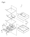
- the battery pack 12 includes an outer shell 21, a rechargeable battery unit 22, and a circuit board 23.
- the rechargeable battery unit 22 and the circuit board 23 are accommodated in the outer shell 21.
- An upper shell 21 a and a lower shell 21 b are integrated with each other to form the outer shell 21.
- a terminal coupler 21x is arranged on an upper surface of the upper shell 21a to electrically connect the battery pack 12 to the tool body 11.
- the terminal coupler 21x is electrically connected to the rechargeable battery unit 22 and the circuit board 23, which are located in the outer shell 21.
- the outer shell 21 is not airproof.
- the rechargeable battery unit 22 includes a battery case 25 and rechargeable battery cells 26.
- the battery case 25 includes a case body 25a and a lid 25b.
- the case body 25a includes at least one inlet to allow for the insertion of the rechargeable battery cells 26.
- the case body 25a is shaped to accommodate the rechargeable battery cells 26.
- the case body 25a may include linear cylindrical bores in a parallel arrangement respectively corresponding to the rechargeable battery cells 26.
- the lid 25b closes the inlet of the case body 25a.
- the lid 25b is securely attached to the case body 25a by, for example, screws 27.
- the lid 25b may include a seal 28 adhered around the entire inlet of the case body 25a.
- the case body 25a and the lid 25b seal the battery case 25 in an airproof manner.
- the case body 25a and the lid 25b function as a water and dustproof structure.
- the outer shell 21 and the battery case 25 cooperate to form a double wall structure.
- the outer shell 21 has a lower level of water and dustproof resistance than the battery case 25.
- a relief valve 29 is arranged on the outer surface, preferably, the upper surface, of the case body 25a of the battery case 25.
- the relief valve 29 releases gas from the battery case 25 when the rechargeable battery cells 26 generate gas.
- the relief pressure of the relief valve 29 may be determined in advance through experiments.
- the inventors of the present invention have formed a battery case of a comparative example to check the effectiveness of the relief valve 29.
- the battery case of the comparative example is identical to the battery case 25 of the illustrated embodiment except that the relief valve 29 is omitted.
- the rechargeable battery cells 26 when the rechargeable battery cells 26 generate gas, pressure builds up in the battery case. This may result in damage, such as cracking, of the battery case.
- the relief pressure of the relief valve 29 is determined so that that the relief valve 29 opens before a pressure buildup in the battery case 25 damages the battery case 25.
- the relief valve 29 releases gas into the void between the battery case 25 and the outer shell 21. The gas is then released from the non-airproof outer shell 21 and out of the battery pack 12.
- the relief valve 29 may include a valve hole, which is located in the outer surface, preferably, the upper surface, of the battery case 25 (case body 25a), and a film, which functions as a valve member.
- the film is thermally fused to the battery case 25 around the valve hole.
- the film is configured to rip when pressure builds up in the battery case 25 and reaches the relief pressure.
- the film may be referred to as a rippable film.
- the film be formed of a material that can be thermally fused to the battery case 25. Instead of being thermally fused, the film may be attached by an adhesive to the battery case 25. When necessary, the film may have a locally weakened structure to finely adjust the ripping initiation location and/or the ripping pressure (relief pressure) of the film.
- Connection terminals 30 project from the outer surface, preferably, the upper surface, of the case body 25a of the battery case 25.
- the connection terminals 30 are locally concentrated and form a connection terminal array.
- the connection terminal array is linear.
- the connection terminals 30 are electrically connected to the rechargeable battery cells 26 in the case body 25a.
- the interval between two adjacent connection terminals 30 is set to a dimension that allows for the passage of water when water reaches the battery case 25.
- a waterproof treatment such as the application of a sealing resin, is performed on each connection terminal 30, for example, around the basal end of the connection terminal 30.
- Each connection terminal 30 may be a terminal formed by a rust-resistant metal or alloy, such as an aluminum terminal. The distal portion of each connection terminal 30 is electrically connected to the circuit board 23.
- the circuit board 23 may include a detection circuit, which detects the battery state such as the voltage of the battery pack 12 (rechargeable battery cells 26), and a display circuit, which displays the detected state.
- the circuit board 23 includes sockets 23a respectively corresponding to the connection terminals 30 of the rechargeable battery unit 22. Each connection terminal 30 is electrically connected to the corresponding socket 23a. Each socket 23a may be a through hole. The connection terminals 30 are inserted into and soldered to the sockets 23a.
- the two opposite surfaces of the circuit board 23 are respectively covered by waterproof sheets 31 a and 31 b.
- the waterproof sheets 31 a and 31b enclose the entire circuit board 23 to protect the circuit board 23 from water and dust. This also protects the portions where the connection terminals 30 and the sockets are connected from water and dust.
- the waterproof sheets 31 a and 31 b function as a water and dustproof structure for the circuit board 23.
- the circuit board 23 and the rechargeable battery unit 22 are accommodated in the outer shell 21. Further, the portions where the circuit board 23 and the rechargeable battery unit 22 are connected are also protected by the water and dustproof structure. Thus, even if water or moisture enters the outer shell 21, failures such as short-circuiting of the circuit board 23 or the rechargeable battery unit 22 are prevented or reduced in the outer shell 21.
- the rechargeable battery unit 22 includes a sealed structure, which provides water and dust resistance, and the relief valve 29, which releases gas from the rechargeable battery unit 22. When the rechargeable battery cell 26 generates gas and the pressure built up in the battery case 25 becomes excessively high, the relief valve 29 functions to prevent damage to the battery case 25.
- the battery pack 12 includes the outer shell 21 and the rechargeable battery unit 22 accommodated in the outer shell 21.
- the rechargeable battery unit 22 includes at least one rechargeable battery cell 26, the battery case 25 that is sealed accommodating the at least one rechargeable battery cell 26, and the relief valve 29 arranged on the battery case 25.
- the relief valve 29 is configured to open when the at least one rechargeable battery cell 26 generates gas and builds up pressure in the battery case 25 to a predetermined value (relief pressure) or greater.
- the battery pack 12 improves the water and dust resistance. Further, when the rechargeable battery cell 26 generates gas, the gas is released from the battery case 25 while preventing or reducing damage to the battery case 25, excluding the relief valve 29. For example, the relief valve 29 may be repaired or replaced so that the battery case 25 can be reused.
- the battery pack 12 includes the circuit board 23 accommodated in the outer shell 21.
- the rechargeable battery unit 22 includes the connection terminals 30 electrically connected to the circuit board 23, and the connection terminals 30 are locally concentrated and form a connection terminal array.
- the battery pack 12 easily realizes a water and dustproof structure for the portions electrically connecting the rechargeable battery unit 22 and the circuit board 23.
- the rechargeable battery cells 26 are encapsulated in the battery case 25 in an airproof manner.
- the battery case 25 is encapsulated in the outer shell 21 in a non-airproof manner.
- the battery pack 12 releases the gas generated in the battery case 25 out of the battery case 25 through the relief valve 29 of the battery case 25 and the non-airproof outer shell 21.
- the relief valve includes a rippable film functioning as a valve member.
- the film is fixed to the battery case around a valve hole.
- the relief valve may be formed by performing a relatively simple thermal fusing process. Further, ripping of the film can be visually checked. For example, a person inspecting the battery pack 12 can visually check for generation events or generation history of gas from the rechargeable battery cell 26. Further, for example, the ripped film may be replaced so that the battery case 25 can be reused.
- the battery case 25 may be formed from a material having a high heat-dissipation effect. Further, the battery case 25 may include a heat-dissipation structure.
- the relief valve 29 of the battery case 25 may be changed in structure. Further, the water and dustproof structure of the rechargeable battery unit 22 (battery case 25) and the water and dustproof structure of the circuit board 23 may be changed.
- the circuit board 23 may be omitted from the battery pack 12.
Landscapes
- Chemical & Material Sciences (AREA)
- Chemical Kinetics & Catalysis (AREA)
- Electrochemistry (AREA)
- General Chemical & Material Sciences (AREA)
- Engineering & Computer Science (AREA)
- Manufacturing & Machinery (AREA)
- Biophysics (AREA)
- Life Sciences & Earth Sciences (AREA)
- Computer Hardware Design (AREA)
- Microelectronics & Electronic Packaging (AREA)
- Mechanical Engineering (AREA)
- Battery Mounting, Suspending (AREA)
- Connection Of Batteries Or Terminals (AREA)
- Gas Exhaust Devices For Batteries (AREA)
Applications Claiming Priority (1)
| Application Number | Priority Date | Filing Date | Title |
|---|---|---|---|
| JP2015017238A JP6587089B2 (ja) | 2015-01-30 | 2015-01-30 | 電池パック |
Publications (2)
| Publication Number | Publication Date |
|---|---|
| EP3051608A1 true EP3051608A1 (de) | 2016-08-03 |
| EP3051608B1 EP3051608B1 (de) | 2026-04-22 |
Family
ID=55177812
Family Applications (1)
| Application Number | Title | Priority Date | Filing Date |
|---|---|---|---|
| EP16151797.4A Active EP3051608B1 (de) | 2015-01-30 | 2016-01-19 | Batteriepack für elektrisches werkzeug |
Country Status (4)
| Country | Link |
|---|---|
| US (1) | US10468648B2 (de) |
| EP (1) | EP3051608B1 (de) |
| JP (1) | JP6587089B2 (de) |
| CN (1) | CN105845846A (de) |
Cited By (7)
| Publication number | Priority date | Publication date | Assignee | Title |
|---|---|---|---|---|
| DE102017107868A1 (de) | 2017-04-11 | 2018-10-11 | Metabowerke Gmbh | Akkupack sowie Elektrohandwerkzeuggerät |
| WO2019002125A1 (de) * | 2017-06-29 | 2019-01-03 | Robert Bosch Gmbh | Handwerkzeugmaschine |
| DE102018104342B3 (de) | 2018-02-26 | 2019-07-04 | Metabowerke Gmbh | Akkupack sowie Elektrohandwerkzeuggerät |
| DE102018109209A1 (de) | 2018-04-18 | 2019-10-24 | Metabowerke Gmbh | Akkupack und Elektrohandwerkzeuggerät |
| WO2020041290A1 (en) * | 2018-08-21 | 2020-02-27 | Tti (Macao Commercial Offshore) Limited | Battery |
| EP3719860A1 (de) * | 2019-04-05 | 2020-10-07 | Makita Corporation | Batteriepack |
| US11038237B2 (en) | 2018-02-26 | 2021-06-15 | Metabowerke Gmbh | Battery pack and electric hand tool |
Families Citing this family (8)
| Publication number | Priority date | Publication date | Assignee | Title |
|---|---|---|---|---|
| JP7038200B2 (ja) * | 2018-05-07 | 2022-03-17 | ▲蘇▼州宝▲時▼得▲電▼▲動▼工具有限公司 | 電池パック及び電動工具ユニット |
| KR102660426B1 (ko) * | 2018-11-07 | 2024-04-23 | 에스케이온 주식회사 | 배터리 모듈 |
| JP7437676B2 (ja) * | 2019-12-10 | 2024-02-26 | パナソニックIpマネジメント株式会社 | 電動工具用電池パック、及び電動工具 |
| JP7437675B2 (ja) * | 2019-12-10 | 2024-02-26 | パナソニックIpマネジメント株式会社 | 電動工具用電池パック、及び電動工具 |
| KR102802977B1 (ko) * | 2020-08-14 | 2025-04-30 | 주식회사 엘지에너지솔루션 | 전지 모듈 및 이를 포함하는 전지팩 |
| JP2022167227A (ja) | 2021-04-22 | 2022-11-04 | パナソニックホールディングス株式会社 | 電動工具用電池パック、及び電動工具 |
| EP4695867A1 (de) * | 2023-04-13 | 2026-02-18 | Techtronic Cordless GP | Batteriepack |
| DE102024103760A1 (de) * | 2024-02-09 | 2025-08-14 | Einhell Germany Ag | Akkumulator für Arbeitsgeräte |
Citations (5)
| Publication number | Priority date | Publication date | Assignee | Title |
|---|---|---|---|---|
| US4835452A (en) * | 1986-09-19 | 1989-05-30 | Sanyo Electric Co., Ltd. | Liquidproof battery-powered appliance |
| US20110111270A1 (en) * | 2008-06-26 | 2011-05-12 | Alexander Osswald | Battery pack and handheld power tool having a battery pack |
| US20120037385A1 (en) * | 2010-08-11 | 2012-02-16 | Makita Corporation | Electric power tool powered by a plurality of single-cell battery packs |
| JP2013191289A (ja) | 2012-03-12 | 2013-09-26 | Max Co Ltd | 電池パック |
| JP2014032862A (ja) * | 2012-08-03 | 2014-02-20 | Hitachi Koki Co Ltd | 電池セル及び電池パック及び電動工具 |
Family Cites Families (12)
| Publication number | Priority date | Publication date | Assignee | Title |
|---|---|---|---|---|
| JPH0662457U (ja) * | 1993-02-15 | 1994-09-02 | 日本電池株式会社 | 密閉型電池 |
| JP2000149887A (ja) * | 1998-11-13 | 2000-05-30 | Mitsubishi Cable Ind Ltd | リチウム電池パックケース |
| JP2006012831A (ja) * | 2004-06-23 | 2006-01-12 | Samsung Sdi Co Ltd | 二次電池,二次電池のキャップ組立体,及び二次電池の安全バルブの取り付け方法 |
| US8071231B2 (en) * | 2006-08-28 | 2011-12-06 | Lg Chem, Ltd. | Secondary battery including one-way exhaust valve |
| JP4311425B2 (ja) | 2006-09-07 | 2009-08-12 | 日立工機株式会社 | 電池パック、充電器、及び電動工具 |
| US20120003738A1 (en) * | 2007-10-04 | 2012-01-05 | University Hospitals Of Cleveland | Method For Amplification And Functional Enhancment Of Blood Derived Progenitor Cells Using A Closed Culture System |
| KR101084836B1 (ko) * | 2009-10-27 | 2011-11-21 | 삼성에스디아이 주식회사 | 배터리 팩 |
| US20130164567A1 (en) * | 2011-06-24 | 2013-06-27 | Seektech, Inc. | Modular battery pack apparatus, systems, and methods |
| US9559501B2 (en) * | 2011-07-11 | 2017-01-31 | General Electric Company | Housing assembly and method of assembling same |
| WO2013019203A1 (en) * | 2011-08-01 | 2013-02-07 | Ingersoll-Rand Company | Multi cell carriers |
| JP2013037873A (ja) * | 2011-08-08 | 2013-02-21 | Panasonic Corp | 電池モジュール |
| US9318729B2 (en) * | 2013-04-05 | 2016-04-19 | Makita Corporation | Power tool battery pack |
-
2015
- 2015-01-30 JP JP2015017238A patent/JP6587089B2/ja active Active
-
2016
- 2016-01-06 US US14/989,643 patent/US10468648B2/en active Active
- 2016-01-19 EP EP16151797.4A patent/EP3051608B1/de active Active
- 2016-01-27 CN CN201610092044.0A patent/CN105845846A/zh active Pending
Patent Citations (5)
| Publication number | Priority date | Publication date | Assignee | Title |
|---|---|---|---|---|
| US4835452A (en) * | 1986-09-19 | 1989-05-30 | Sanyo Electric Co., Ltd. | Liquidproof battery-powered appliance |
| US20110111270A1 (en) * | 2008-06-26 | 2011-05-12 | Alexander Osswald | Battery pack and handheld power tool having a battery pack |
| US20120037385A1 (en) * | 2010-08-11 | 2012-02-16 | Makita Corporation | Electric power tool powered by a plurality of single-cell battery packs |
| JP2013191289A (ja) | 2012-03-12 | 2013-09-26 | Max Co Ltd | 電池パック |
| JP2014032862A (ja) * | 2012-08-03 | 2014-02-20 | Hitachi Koki Co Ltd | 電池セル及び電池パック及び電動工具 |
Cited By (9)
| Publication number | Priority date | Publication date | Assignee | Title |
|---|---|---|---|---|
| DE102017107868A1 (de) | 2017-04-11 | 2018-10-11 | Metabowerke Gmbh | Akkupack sowie Elektrohandwerkzeuggerät |
| WO2019002125A1 (de) * | 2017-06-29 | 2019-01-03 | Robert Bosch Gmbh | Handwerkzeugmaschine |
| DE102018104342B3 (de) | 2018-02-26 | 2019-07-04 | Metabowerke Gmbh | Akkupack sowie Elektrohandwerkzeuggerät |
| US11038237B2 (en) | 2018-02-26 | 2021-06-15 | Metabowerke Gmbh | Battery pack and electric hand tool |
| DE102018109209A1 (de) | 2018-04-18 | 2019-10-24 | Metabowerke Gmbh | Akkupack und Elektrohandwerkzeuggerät |
| WO2020041290A1 (en) * | 2018-08-21 | 2020-02-27 | Tti (Macao Commercial Offshore) Limited | Battery |
| AU2019326433B2 (en) * | 2018-08-21 | 2022-02-24 | Tti (Macao Commercial Offshore) Limited | Battery |
| EP3719860A1 (de) * | 2019-04-05 | 2020-10-07 | Makita Corporation | Batteriepack |
| US11677116B2 (en) | 2019-04-05 | 2023-06-13 | Makita Corporation | Battery pack |
Also Published As
| Publication number | Publication date |
|---|---|
| JP6587089B2 (ja) | 2019-10-09 |
| US20160226044A1 (en) | 2016-08-04 |
| US10468648B2 (en) | 2019-11-05 |
| JP2016143507A (ja) | 2016-08-08 |
| EP3051608B1 (de) | 2026-04-22 |
| CN105845846A (zh) | 2016-08-10 |
Similar Documents
| Publication | Publication Date | Title |
|---|---|---|
| EP3051608A1 (de) | Batteriepack für elektrisches werkzeug | |
| JP5663962B2 (ja) | 電池ユニット | |
| US11165126B2 (en) | Battery pouch, battery cell and method of making a pouch or battery cell | |
| US10090498B2 (en) | Modular battery pack apparatus, systems, and methods including viral data and/or code transfer | |
| KR101979371B1 (ko) | 배터리 모듈 및 이를 포함하는 배터리 팩 | |
| KR102540916B1 (ko) | 과충전 안전장치 | |
| EP3644398A1 (de) | Batteriemodulgehäuse mit leicht wiederverwendbarer, recycelbarer und wiederaufbereitbarer adhäsionsstruktur und batteriemodul damit | |
| JP5357987B2 (ja) | 電池用防火装置 | |
| US20060001404A1 (en) | Battery pack for hand-held electric machine tools | |
| US20120288741A1 (en) | Battery assembly | |
| JP2009043592A (ja) | バッテリモジュール | |
| CN111149236B (zh) | 电池组 | |
| KR20170075484A (ko) | 이차전지 팩 | |
| KR20130078953A (ko) | 차량용 배터리안전장치 | |
| CN102077388A (zh) | 电池组和具有电池组的手持式工具机 | |
| CN108370002A (zh) | 蓄电装置、框体的密闭结构及框体的制造方法 | |
| KR102013411B1 (ko) | 배터리 모듈 및 이를 포함하는 배터리 팩 | |
| JP6003838B2 (ja) | 電池モジュールおよび電池モジュールを備えた電池パック | |
| JP6756955B2 (ja) | 蓄電装置 | |
| JP2014241296A (ja) | 電池ユニット | |
| JP6840397B2 (ja) | 蓄電装置 | |
| KR20130098336A (ko) | 적어도 하나의 압력 경감 장치를 구비한 전기 화학 셀 | |
| JP2008171662A (ja) | 電池パック | |
| KR20170046608A (ko) | 회로 기판 및 전자 부품의 실장 방법 | |
| JP6751939B2 (ja) | 蓄電装置 |
Legal Events
| Date | Code | Title | Description |
|---|---|---|---|
| PUAI | Public reference made under article 153(3) epc to a published international application that has entered the european phase |
Free format text: ORIGINAL CODE: 0009012 |
|
| 17P | Request for examination filed |
Effective date: 20160127 |
|
| AK | Designated contracting states |
Kind code of ref document: A1 Designated state(s): AL AT BE BG CH CY CZ DE DK EE ES FI FR GB GR HR HU IE IS IT LI LT LU LV MC MK MT NL NO PL PT RO RS SE SI SK SM TR |
|
| AX | Request for extension of the european patent |
Extension state: BA ME |
|
| STAA | Information on the status of an ep patent application or granted ep patent |
Free format text: STATUS: EXAMINATION IS IN PROGRESS |
|
| 17Q | First examination report despatched |
Effective date: 20180531 |
|
| REG | Reference to a national code |
Ref country code: DE Ref legal event code: R079 Free format text: PREVIOUS MAIN CLASS: H01M0002100000 Ipc: H01M0010420000 Ref country code: DE Ref legal event code: R079 Ref document number: 602016095252 Country of ref document: DE Free format text: PREVIOUS MAIN CLASS: H01M0002100000 Ipc: H01M0010420000 |
|
| GRAP | Despatch of communication of intention to grant a patent |
Free format text: ORIGINAL CODE: EPIDOSNIGR1 |
|
| STAA | Information on the status of an ep patent application or granted ep patent |
Free format text: STATUS: GRANT OF PATENT IS INTENDED |
|
| INTG | Intention to grant announced |
Effective date: 20251124 |
|
| RIC1 | Information provided on ipc code assigned before grant |
Ipc: H01M 10/42 20060101AFI20251117BHEP Ipc: B25B 21/00 20060101ALI20251117BHEP Ipc: H01M 50/342 20210101ALI20251117BHEP Ipc: H01M 50/296 20210101ALI20251117BHEP Ipc: H01M 50/284 20210101ALI20251117BHEP Ipc: H01M 50/247 20210101ALI20251117BHEP Ipc: H01M 50/24 20210101ALI20251117BHEP Ipc: H01M 50/213 20210101ALI20251117BHEP |
|
| GRAS | Grant fee paid |
Free format text: ORIGINAL CODE: EPIDOSNIGR3 |
|
| GRAA | (expected) grant |
Free format text: ORIGINAL CODE: 0009210 |
|
| STAA | Information on the status of an ep patent application or granted ep patent |
Free format text: STATUS: THE PATENT HAS BEEN GRANTED |
|
| AK | Designated contracting states |
Kind code of ref document: B1 Designated state(s): AL AT BE BG CH CY CZ DE DK EE ES FI FR GB GR HR HU IE IS IT LI LT LU LV MC MK MT NL NO PL PT RO RS SE SI SK SM TR |
|
| REG | Reference to a national code |
Ref country code: CH Ref legal event code: F10 Free format text: ST27 STATUS EVENT CODE: U-0-0-F10-F00 (AS PROVIDED BY THE NATIONAL OFFICE) Effective date: 20260422 Ref country code: GB Ref legal event code: FG4D |