EP3050870B1 - Verfahren zur Herstellung von 3-Aminomethyl-3,5,5-trimethylcyclohexylamin - Google Patents
Verfahren zur Herstellung von 3-Aminomethyl-3,5,5-trimethylcyclohexylamin Download PDFInfo
- Publication number
- EP3050870B1 EP3050870B1 EP15153287.6A EP15153287A EP3050870B1 EP 3050870 B1 EP3050870 B1 EP 3050870B1 EP 15153287 A EP15153287 A EP 15153287A EP 3050870 B1 EP3050870 B1 EP 3050870B1
- Authority
- EP
- European Patent Office
- Prior art keywords
- catalyst
- weight
- hydrogenation
- ammonia
- particle sizes
- Prior art date
- Legal status (The legal status is an assumption and is not a legal conclusion. Google has not performed a legal analysis and makes no representation as to the accuracy of the status listed.)
- Active
Links
Images
Classifications
-
- B—PERFORMING OPERATIONS; TRANSPORTING
- B01—PHYSICAL OR CHEMICAL PROCESSES OR APPARATUS IN GENERAL
- B01J—CHEMICAL OR PHYSICAL PROCESSES, e.g. CATALYSIS OR COLLOID CHEMISTRY; THEIR RELEVANT APPARATUS
- B01J25/00—Catalysts of the Raney type
-
- B—PERFORMING OPERATIONS; TRANSPORTING
- B01—PHYSICAL OR CHEMICAL PROCESSES OR APPARATUS IN GENERAL
- B01J—CHEMICAL OR PHYSICAL PROCESSES, e.g. CATALYSIS OR COLLOID CHEMISTRY; THEIR RELEVANT APPARATUS
- B01J25/00—Catalysts of the Raney type
- B01J25/02—Raney nickel
-
- B—PERFORMING OPERATIONS; TRANSPORTING
- B01—PHYSICAL OR CHEMICAL PROCESSES OR APPARATUS IN GENERAL
- B01J—CHEMICAL OR PHYSICAL PROCESSES, e.g. CATALYSIS OR COLLOID CHEMISTRY; THEIR RELEVANT APPARATUS
- B01J35/00—Catalysts, in general, characterised by their form or physical properties
- B01J35/40—Catalysts, in general, characterised by their form or physical properties characterised by dimensions, e.g. grain size
-
- B—PERFORMING OPERATIONS; TRANSPORTING
- B01—PHYSICAL OR CHEMICAL PROCESSES OR APPARATUS IN GENERAL
- B01J—CHEMICAL OR PHYSICAL PROCESSES, e.g. CATALYSIS OR COLLOID CHEMISTRY; THEIR RELEVANT APPARATUS
- B01J35/00—Catalysts, in general, characterised by their form or physical properties
- B01J35/50—Catalysts, in general, characterised by their form or physical properties characterised by their shape or configuration
-
- B—PERFORMING OPERATIONS; TRANSPORTING
- B01—PHYSICAL OR CHEMICAL PROCESSES OR APPARATUS IN GENERAL
- B01J—CHEMICAL OR PHYSICAL PROCESSES, e.g. CATALYSIS OR COLLOID CHEMISTRY; THEIR RELEVANT APPARATUS
- B01J37/00—Processes, in general, for preparing catalysts; Processes, in general, for activation of catalysts
- B01J37/0009—Use of binding agents; Moulding; Pressing; Powdering; Granulating; Addition of materials ameliorating the mechanical properties of the product catalyst
- B01J37/0018—Addition of a binding agent or of material, later completely removed among others as result of heat treatment, leaching or washing,(e.g. forming of pores; protective layer, desintegrating by heat)
-
- B—PERFORMING OPERATIONS; TRANSPORTING
- B01—PHYSICAL OR CHEMICAL PROCESSES OR APPARATUS IN GENERAL
- B01J—CHEMICAL OR PHYSICAL PROCESSES, e.g. CATALYSIS OR COLLOID CHEMISTRY; THEIR RELEVANT APPARATUS
- B01J37/00—Processes, in general, for preparing catalysts; Processes, in general, for activation of catalysts
- B01J37/0009—Use of binding agents; Moulding; Pressing; Powdering; Granulating; Addition of materials ameliorating the mechanical properties of the product catalyst
- B01J37/0063—Granulating
-
- B—PERFORMING OPERATIONS; TRANSPORTING
- B01—PHYSICAL OR CHEMICAL PROCESSES OR APPARATUS IN GENERAL
- B01J—CHEMICAL OR PHYSICAL PROCESSES, e.g. CATALYSIS OR COLLOID CHEMISTRY; THEIR RELEVANT APPARATUS
- B01J37/00—Processes, in general, for preparing catalysts; Processes, in general, for activation of catalysts
- B01J37/0081—Preparation by melting
-
- C—CHEMISTRY; METALLURGY
- C07—ORGANIC CHEMISTRY
- C07C—ACYCLIC OR CARBOCYCLIC COMPOUNDS
- C07C209/00—Preparation of compounds containing amino groups bound to a carbon skeleton
- C07C209/44—Preparation of compounds containing amino groups bound to a carbon skeleton by reduction of carboxylic acids or esters thereof in presence of ammonia or amines, or by reduction of nitriles, carboxylic acid amides, imines or imino-ethers
- C07C209/48—Preparation of compounds containing amino groups bound to a carbon skeleton by reduction of carboxylic acids or esters thereof in presence of ammonia or amines, or by reduction of nitriles, carboxylic acid amides, imines or imino-ethers by reduction of nitriles
-
- C—CHEMISTRY; METALLURGY
- C07—ORGANIC CHEMISTRY
- C07C—ACYCLIC OR CARBOCYCLIC COMPOUNDS
- C07C209/00—Preparation of compounds containing amino groups bound to a carbon skeleton
- C07C209/44—Preparation of compounds containing amino groups bound to a carbon skeleton by reduction of carboxylic acids or esters thereof in presence of ammonia or amines, or by reduction of nitriles, carboxylic acid amides, imines or imino-ethers
- C07C209/52—Preparation of compounds containing amino groups bound to a carbon skeleton by reduction of carboxylic acids or esters thereof in presence of ammonia or amines, or by reduction of nitriles, carboxylic acid amides, imines or imino-ethers by reduction of imines or imino-ethers
-
- B—PERFORMING OPERATIONS; TRANSPORTING
- B01—PHYSICAL OR CHEMICAL PROCESSES OR APPARATUS IN GENERAL
- B01J—CHEMICAL OR PHYSICAL PROCESSES, e.g. CATALYSIS OR COLLOID CHEMISTRY; THEIR RELEVANT APPARATUS
- B01J2523/00—Constitutive chemical elements of heterogeneous catalysts
-
- C—CHEMISTRY; METALLURGY
- C07—ORGANIC CHEMISTRY
- C07C—ACYCLIC OR CARBOCYCLIC COMPOUNDS
- C07C2601/00—Systems containing only non-condensed rings
- C07C2601/12—Systems containing only non-condensed rings with a six-membered ring
- C07C2601/14—The ring being saturated
Definitions
- the invention relates to an improved process for the preparation of 3-aminomethyl-3,5,5-trimethylcyclohexylamine, hereinafter referred to as isophoronediamine or abbreviated to IPDA, by means of catalytic hydrogenation and/or catalytic reductive amination (also referred to as aminating hydrogenation) of 3-cyano-3,5,5-trimethylcyclohexanone, hereinafter referred to as isophoronenitrile or abbreviated to IPN.
- IPDA 3-aminomethyl-3,5,5-trimethylcyclohexylamine
- IPN isophoronenitrile
- IPDA aminating hydrogenation of IPN
- IPN is reacted in the presence of hydrogen and an excess of ammonia on a cobalt catalyst.
- IPNI isophorone nitrile imine
- IPDA IPDA in this type of reaction
- the yield of IPDA in this type of reaction is largely determined by the excess of ammonia.
- the maximum IPDA yield achieved is around 80%.
- the main by-product is the so-called amino alcohol, IPAA, which results from the direct hydrogenation of the IPN.
- IPDA yield is achieved when the formation of IPNI is accelerated by using suitable imination catalysts.
- imination catalysts are acidic ion exchange resins (EP 042 119 ) are also suitable.
- Acidic metal oxides EP 449 089
- organopolysiloxanes containing sulfonic acid groups EP 816 323
- heteropolyacids DE 44 26 472
- activated carbon EP 061 137
- other by-products are also significantly reduced, such as bicyclic compounds and by-products resulting from the elimination of HCN.
- HCN acts as a catalyst poison and leads to a deactivation of the hydrogenation catalyst (EP 394 967 A1 , page 2 line 34 ff, page 3 line 44 ff). It is therefore recommended to carry out the imination step in such a way that as little HCN as possible is split off.
- Quaternary ammonium bases can also be used to increase selectivity in the production of IPDA.
- Catalysts modified accordingly have a significantly longer service life than alkali-modified catalysts, especially when a solvent is used.
- WO 2005/039764 A reveals a Raney catalyst.
- JP S62 123154 A discloses a process for producing isophorone nitrile.
- JP H07 188126 A discloses a process for producing isophoronediamine from isophoronenitrile.
- the underlying task was to find a process for the preparation of 3-aminomethyl-3,5,5-trimethylcyclohexylamine by hydrogenation of isophorone nitrile, whereby the yield and selectivity in the reductive amination of isophorone nitrile to produce isophoronediamine should be improved.
- catalysts in the form of powders or shaped bodies such as extrudates or pressed powders, are usually used.
- Full catalysts, Raney-type catalysts or supported catalysts can be used. Raney-type and supported catalysts are preferred, as in the EP 2649042A described in detail.
- the catalyst used according to the invention consisting of a metal alloy in granular form of certain particle sizes after activation by alkalis, the The aim of the invention is achieved and, in addition, a higher activity and better long-term stability of the catalyst were observed.
- the catalyst consists of a metal alloy, whereby the metal alloy is activated by bases on the surface.
- the layer thickness of the activated layer on the particle surface of the catalyst is preferably 50 to 1000 micrometers ( ⁇ m). However, it can also be larger or smaller.
- the catalytically active composition is therefore located on the surface. of the catalyst. However, it is also possible within the scope of the invention to leach out the entire catalyst particle almost completely or completely.
- the catalyst used according to the invention is present as granules in the form of individual particles.
- Totality means that the composition does not differentiate between the content of metals on the surface and in the activated layer and in the core of the catalyst particles, but everything is added together and calculated.
- the catalyst is in the form of irregular particles, i.e. granules.
- the particle sizes of the catalyst i.e. the granulate particles, vary from 2.5 to 6 millimeters (mm).
- the particle sizes of the catalyst i.e. the granulate particles, vary from 3 to 7 millimeters (mm).
- the particle sizes of the catalyst i.e. the granulate particles, vary from 2 to 5 millimeters (mm).
- the specified particle sizes can also have a statistical distribution of size within the ranges. Both narrow distributions and broad distributions are possible according to the invention.
- the distribution of particle sizes and the measurement of particle sizes can be determined by laser methods (ISO 13320, 2012), light methods or image methods.
- the catalyst used according to the invention is preferably obtained by sieving the granules produced. This produces so-called sieve fractions. Individual sieve fractions can be mixed, or a catalyst can be obtained by sieving once or several times.
- the catalysts produced in this way have a statistical distribution of particle sizes, usually in the form of a Gaussian distribution. Symmetrical but also asymmetrical distributions are possible.
- the particle sizes of the catalyst i.e. the granulate particles
- the particle sizes of the catalyst vary with a statistical distribution between 2.5 and 5.5 millimeters (mm), whereby up to 10 percent of the particles can also lie outside the mentioned range of the mentioned lower limit or upper limit, but also up to 10 percent each outside the mentioned range of the mentioned lower limit and upper limit.
- the particle sizes of the catalyst i.e. the granulate particles
- the particle sizes of the catalyst vary with a statistical distribution between 3.5 and 6.5 millimeters (mm), whereby up to 10 percent of the particles can also lie outside the stated range of the stated lower limit or upper limit, but also up to 10 percent each outside the stated range of the stated lower limit and upper limit.
- the particle sizes of the catalyst i.e. the granulate particles
- the particle sizes of the catalyst vary with a statistical distribution between 2 and 5 millimeters (mm), whereby up to 10 percent of the particles can also lie outside the stated range of the stated lower limit or upper limit, but also up to 10 percent each outside the stated range of the stated lower limit and upper limit.
- the particle sizes of the catalyst i.e. the granulate particles
- the particle sizes of the catalyst vary with a statistical distribution between 3 and 7 millimeters (mm), whereby up to 10 percent of the particles can also lie outside the stated range of the stated lower limit or upper limit, but also up to 10 percent each outside the stated range of the stated lower limit and upper limit.
- the alloy is produced thermally, for example in an induction furnace.
- the metals are melted and an alloy is obtained.
- the finished melt is then cast into bars for further processing, for example.
- the alloy is processed into granules using suitable equipment, for example pre-crushed using a jaw crusher and then further ground using a roller mill.
- a sieving step is used to obtain the desired size distribution of the granules by selecting the appropriate sieves (e.g. 3 - 7 mm).
- the catalyst is activated in suitable equipment.
- Organic or inorganic bases can be used.
- a lye e.g. sodium hydroxide solution
- the concentration of the lye can be between 5 and 30% by weight and the reaction temperature between 50 and 100 °C.
- the degree of activation is determined by the temperature and the reaction time. The reaction time is variable and depends on the reaction conditions and the desired degree of activation. After activation, the catalyst is washed with water and then stored under water.
- compositions can be produced analogously in production step a) by selecting the appropriate amounts of metal.
- the catalyst is preferably produced in the order described. However, the catalyst can also be activated before the granules are produced.
- the catalysts can also contain doping metals or other modifiers.
- Typical doping metals are, for example, Mo, Fe, Ag, V, Ga, In, Bi, Ti, Zr and Mn as well as the rare earths, alone or in mixtures.
- Typical modifiers are, for example, those with which the acid-base properties of the catalysts can be influenced, preferably alkali and alkaline earth metals or their compounds, preferably Mg and Li compounds. In the event that such compounds are contained, in a maximum amount of approx.
- the proportion of the above-mentioned metals Co and Al and optionally Cr and Ni in the catalyst is reduced accordingly, with the proportions of Co and Al and optionally Cr and Ni then adding up to at least 95% by weight after activation, based on the metals contained.
- isophorone nitrile is aminatingly hydrogenated directly in the presence of ammonia, hydrogen, a catalyst and optionally other additives and in the presence or absence of organic solvents.
- isophorone nitrile is first converted in whole or in part into isophorone nitrile imine in a separate reactor or reactor section, and this isophorone nitrile imine is subjected to aminating hydrogenation as a pure substance or in a mixture with other components, such as unreacted isophorone nitrile, in the presence of at least ammonia and hydrogen and a catalyst.
- a preferred embodiment of the process according to the invention for producing IPDA is a two-stage process: In the first stage, at least part of the IPN used is converted into isophorone nitrile imine by reaction with ammonia in the presence or absence of an imination catalyst and/or solvents.
- the conversion of IPN to IPNI after the imination should be greater than 80%, preferably greater than 90%, particularly preferably greater than 95%.
- the reaction product of the first stage is subjected to aminating hydrogenation over hydrogenation catalysts in the presence of at least ammonia and hydrogen and in the presence or absence of an organic solvent at a temperature of 20 to 150 °C, preferably 40 to 130 °C, and a pressure of 0.3 to 50 MPa, preferably 5 to 30 MPa.
- the conversion of IPN to IPDA takes place in three separate reaction chambers.
- the first reaction chamber the conversion of IPN to isophorone nitrile imine takes place with excess ammonia over imination catalysts at temperatures between 20 and 150 °C and pressures between 5 and 30 MPa.
- the resulting reaction products are hydrogenated with hydrogen in the presence of excess ammonia over hydrogenation catalysts at temperatures between 20 and 130 °C and pressures of 5 to 30 MPa.
- the resulting reaction products are hydrogenated over the catalysts to be used according to the invention at temperatures between 100 and 160 °C and pressures of 5 to 30 MPa.
- imination catalysts known from the state of the art can be used for this purpose.
- Suitable catalysts are, for example, inorganic or organic ion exchangers (see EP 042 119 ), supported heteropolyacids (see DE 44 26 472 ), acidic metal oxides, especially aluminium oxide and titanium dioxide (see EP 449 089 )
- Organopolysiloxanes containing sulfonic acid groups DE 196 27 265.3
- acidic zeolites and activated carbon EP 061 137 ).
- the reaction temperature can be between 10 and 150 °C, preferably between 30 and 130 °C and very particularly preferably between 40 and 100 °C.
- the pressure is between the autogenous pressure of the mixture and 50 MPa.
- the imination reaction is preferably carried out at the pressure at which the subsequent reductive amination is also carried out.
- Suitable solvents are monohydric alcohols with 1 to 4 carbon atoms, especially methanol, and ethers, especially THF, MTBE and dioxane.
- Typical catalyst loadings are in the range of 0.01 to 10 kg of IPN per kg of catalyst per hour, preferably 0.5 to 10 and particularly preferably 0.5 to 5 kg of IPN per kg of catalyst per hour.
- the catalyst can be in the form of a suspension catalyst or fixed bed catalyst.
- the use of fixed bed catalysts is advantageous.
- IPN and ammonia are passed continuously from bottom to top through a reaction tube filled with imination catalyst.
- Suitable reactor types include shaft furnaces, tray reactors or tube bundle reactors.
- the hydrogen required for hydrogenation can be fed to the reactor either in excess, for example with up to 10,000 molar equivalents, or only in such an amount that the hydrogen consumed by the reaction and the part of the hydrogen that leaves the reactor dissolved in the product stream are replenished.
- the hydrogen can be fed in cocurrent or countercurrent.
- the hydrogenation is carried out in liquid ammonia as solvent. Between 1 and 500 mol, preferably 5 and 200 mol, particularly preferably between 5 and 100 mol of ammonia are used per mole of IPN. It is expedient to use at least the amount of ammonia that was set in the preceding imination. However, the ammonia content can also be increased to the desired value before the hydrogenation by adding additional ammonia.
- the required volume of hydrogenation catalysts to be used depends on the
- the LHSV value liquid hourly space velocity
- the LHSV value is usually between 0.5 and 5 liters of IPN/ammonia mixture per liter of catalyst per hour, preferably between 1 and 4 l Lsg I Kat -1 h -1 .
- the conditioning is preferably carried out in the presence of hydrogen, the partial pressure of the hydrogen used in the reactor being in the range from 0.1 to 50 MPa, preferably 5 to 40 MPa, particularly preferably 10 to 30 MPa.
- the period of conditioning depends on the amount of ammonia used and is preferably between 1 and 48 hours, particularly preferably between 12 and 24 hours.
- the mixture containing isophorone nitrile imine is hydrogenated in the presence of the hydrogenation catalyst in the second stage.
- the mixture fed to the hydrogenation stage can be directly that which is obtained in the imination of IPN with ammonia in the first stage, or as it is obtained after addition or removal of components such as ammonia, organic solvents, bases, cyanide salts, hydrocyanic acid and/or water.
- the hydrogenation is preferably carried out continuously in fixed bed reactors which can be operated in trickle bed or liquid phase mode. Suitable reactor types are, for example, shaft furnaces, tray reactors or tube bundle reactors. It is also possible to connect several fixed bed reactors in series for the hydrogenation, with each of the reactors being operated optionally in trickle bed or liquid phase mode.
- this can also contain fractions boiling higher or lower than IPDA from the distillative processing of the reaction mixture withdrawn from the trickle bed reactor.
- IPDA residues such fractions can also contain by-products from which IPDA is formed again under reaction conditions.
- recycle the fraction boiling above IPDA which contains 2-aza-4,6,6-trimethylbicyclo[3.2.1]-octane as the main product in addition to IPDA residues.
- the isomer ratio can be influenced by choosing a temperature profile in the hydrogenation step. It is possible, for example, to initially partially hydrogenate a mixture containing IPN or isophorone nitrile imine at a temperature between 20 and 90 °C and then to complete the reaction in a second step in a temperature range between 90 and 150 °C. By maintaining relatively low reaction temperatures in the first step, the selectivity can be shifted in favor of the cis isomer. Maintaining relatively low reaction temperatures at the start of the reaction also has the advantage that the thermally labile isophorone nitrile imine is hydrogenated particularly gently, thereby preventing side reactions.
- the isophorone amino nitrile formed as an intermediate is significantly more thermally stable and can therefore be hydrogenated at higher temperatures without having to fear further side reactions.
- the release of HCN is also one of the undesirable side reactions.
- a certain concentration of cyanide ions has a positive effect on the selectivity of the hydrogenation stage. This effect is more pronounced when the cyanide ions are present in the hydrogenation stage from the very beginning and do not only form during the hydrogenation. Therefore, the release of HCN during the hydrogenation stage must be prevented.
- the desired temperature profile can be achieved, for example, by connecting two or more separately heated reactors in series. However, it is also possible to achieve an increasing temperature profile in just one hydrogenation reactor.
- the hydrogenation reaction is particularly preferably carried out in an adiabatically operated trickle bed reactor in which the reaction mixture is fed into the reactor at temperatures between 20 and 90 °C and leaves again between 90 and 150 °C due to the reaction heat that occurs and is absorbed by the reaction mixture.
- the reaction mixture leaving the hydrogenation is further purified using the usual methods to obtain an IPDA with the desired quality. All common separation methods such as distillation, flash evaporation, crystallization, extraction, sorption, permeation, phase separation or combinations of the above can be used.
- the purification can be carried out continuously, batchwise, in one or more stages, in a vacuum or under pressure. Possible components that are separated during further purification, for example, are hydrogen, ammonia, water and the by-products arising during the production of IPDA from IPN such as hydrogenated HCN elimination products or impurities of the IPN, methylated by-products and/or incompletely hydrogenated intermediates.
- Purification is preferably achieved by distillation under pressure and/or in a vacuum in several steps.
- Any distillation column with and without internals such as dephlegmators, dividing walls, random internals or beds, ordered internals or packings, trays with or without forced guidance can be used for this purpose.
- a first step in particular hydrogen, inert gases, ammonia, low-boiling impurities and possibly also water are completely or partially separated in one or more distillation columns.
- the separation preferably takes place at a pressure that is lower than in the reaction step. If the separation takes place in several distillation steps, it is advantageous that the pressure is reduced step by step.
- the separation is particularly preferably carried out above 1 bar and at bottom temperatures of 0 - 200 °C.
- the use of a stripping gas to remove low-boiling impurities can be advantageous.
- ammonia and hydrogen and portions of the low-boiling impurities can be fully or partially returned to the process (reaction).
- the low-boiling impurities and possibly portions of hydrogen and ammonia are fed for thermal utilization.
- a second step other low-boiling impurities, water and high-boiling impurities are completely or partially separated.
- This can be done in one or more distillation columns. Water can be distilled off at the top of the column together with organic, low-boiling impurities and, if necessary, portions of IPDA and, after condensation, separated into an aqueous and an organic phase. The organic phase can be partially returned to the column as reflux.
- the second step of distillation is carried out in a single column (e.g. a dividing wall column), the IPDA with the desired purity is removed via a side stream, while the high-boiling impurities are obtained in the bottom of the column.
- the IPDA is obtained at the top of a column.
- the separation of the low and high boiling impurities and of water is preferably carried out in a vacuum between 100 Pa and 0.0999 MPa and sump temperatures of 50 - 300 °C. All secondary components can be fed into thermal recycling.
- the alloy is produced in an induction furnace.
- the metals are melted in the appropriate quantities at 1500°C.
- the finished melt is cast into bars for further processing.
- the alloy bars are pre-crushed using a jaw crusher and then ground further using a roller mill.
- the desired size distribution of the granules is achieved by selecting the appropriate sieves in a sieving step.
- the catalyst is activated in a standard glass laboratory apparatus, e.g. a beaker.
- An aqueous lye e.g. sodium hydroxide solution
- the granules are in a catalyst basket during activation.
- An exothermic process dissolves part of the aluminum from the alloy, forming hydrogen and sodium aluminate lye.
- the concentration of the lye used was 20% by weight and the reaction temperature was 90 °C. The degree of activation was determined by the reaction time. After activation, the catalyst is washed with water and then stored under water.
- the catalyst used has the following composition in its entirety in weight percent (wt.%), where the proportions add up to 100 wt.%, based on the metals contained: Cobalt: 75.9 wt.% Aluminum: 20.0 wt.% Chrome: 1.5 wt.% Nickel: 2.6 wt.%
- a sieve fraction was used with particle sizes of the catalyst, i.e. the granulate particles with a statistical distribution between 2.0 and 5.0 millimeters (mm), whereby up to 10 percent of the particles can also be outside the stated range of the stated lower limit or upper limit, but also up to 10 percent each outside the stated range of the stated lower limit and upper limit.
- the catalysts are tested for their catalytic activity in the production of 3-aminomethyl-3,5,5-trimethylcyclohexylamine (isophoronediamine, IPDA) from 3-cyano-3,5,5-trimethylcyclohexanone (isophoronenitrile, IPN) in a two-step process.
- IPDA 3-aminomethyl-3,5,5-trimethylcyclohexylamine
- IPN isophoronenitrile
- isophorone nitrile is at least partially converted to 3-cyano-3,5,5-trimethylcyclohexanimine in the presence of an imination catalyst with ammonia and in the second stage it is aminatingly hydrogenated on a hydrogenation catalyst at a temperature of 60-100°C and a pressure of 250 bar with hydrogen in the presence of ammonia.
- a hydrogenation catalyst at a temperature of 60-100°C and a pressure of 250 bar with hydrogen in the presence of ammonia.
- the hydrogenation reactor is filled with 42 ml of the catalyst to be tested.
- the feed solution of IPN (15 wt. %) and ammonia (85 wt. %) is pumped through the reaction tube from top to bottom at a mass flow of 110 ml/h.
- the hydrogen is added separately from above at a volume flow of 40 l/h.
- the product liquid is collected in a separating vessel under the reactor.
- the collected product mixture is analyzed for IPDA and corresponding secondary components by gas chromatography. The results are shown in Table 1.
- isophorone nitrile is at least partially converted to 3-cyano-3,5,5-trimethylcyclohexanimine in the presence of an imination catalyst with ammonia and in the second stage it is aminatingly hydrogenated on a hydrogenation catalyst at a temperature of 60 °C (catalyst according to the invention) or 100 °C (reference catalyst, supported pressed co-molded body) and a pressure of 250 bar with hydrogen in the presence of ammonia.
- a hydrogenation catalyst at a temperature of 60 °C (catalyst according to the invention) or 100 °C (reference catalyst, supported pressed co-molded body) and a pressure of 250 bar with hydrogen in the presence of ammonia.
- the hydrogenation reactor is filled with 100 ml of the catalyst to be tested.
- the feed solution of IPN (22 wt.%) and ammonia (78 wt.%) is mixed with at a mass flow of 120 g/h from top to bottom through the reaction tube.
- hydrogen is also added from above at a volume flow of 50 l/h.
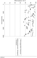
- the product liquid is collected in a separating vessel under the reactor.
- the collected product mixture is analyzed for IPDA and corresponding secondary components by gas chromatography. The results are shown in Figure 1 listed.
- Catalyst used according to the invention Co-granulate of the composition as described above
- Reference catalyst Supported pressed co-catalyst molded body
Landscapes
- Chemical & Material Sciences (AREA)
- Organic Chemistry (AREA)
- Engineering & Computer Science (AREA)
- Materials Engineering (AREA)
- Chemical Kinetics & Catalysis (AREA)
- Organic Low-Molecular-Weight Compounds And Preparation Thereof (AREA)
- Low-Molecular Organic Synthesis Reactions Using Catalysts (AREA)
- Catalysts (AREA)
Description
- Die Erfindung betrifft ein verbessertes Verfahren zur Herstellung von 3-Aminomethyl-3,5,5-trimethylcyclohexylamin, nachfolgend Isophorondiamin oder abgekürzt IPDA genannt, mittels katalytischer Hydrierung und/oder katalytischer reduktiver Aminierung (auch als aminierende Hydrierung bezeichnet) von 3-Cyano-3,5,5-trimethylcyclohexanon, nachfolgend Isophoronnitril oder abgekürzt IPN genannt.
- Die Herstellung von IPDA durch aminierende Hydrierung von IPN ist bekannt und bereits mehrfach beschrieben worden.
- Im einfachsten Fall (
US 3,352,913 ) wird IPN in Gegenwart von Wasserstoff und eines Überschusses an Ammoniak an einem Cobaltkatalysator zur Reaktion gebracht. Zunächst bildet sich aus IPN und Ammoniak durch Wasserabspaltung das Isophoronnitrilimin, IPNI, das nachfolgend zum IPDA hydriert wird.
- Die Ausbeute an IPDA wird bei dieser Art der Reaktionsführung maßgeblich durch den Überschuss an Ammoniak bestimmt. Die maximal erzielten IPDA-Ausbeuten liegen bei ca. 80 %. Hauptnebenprodukt ist der sogenannte Aminoalkohol, IPAA, der aus der direkten Hydrierung des IPN resultiert.

- Eine wesentliche Steigerung der IPDA-Ausbeute wird erreicht, wenn die Bildung des IPNI durch Einsatz geeigneter Iminierungskatalysatoren beschleunigt wird. Als Iminierungskatalysatoren sind z. B. saure lonenaustauscherharze (
EP 042 119 EP 449 089 EP 816 323 DE 44 26 472 ) und Aktivkohle (EP 061 137 - Auf die Problematik der Abspaltung von HCN aus gamma-Ketonitrilen, wie dem IPN, wird in der Literatur besonders hingewiesen (
US 3,352,913 ). Zum Einen wird bemerkt, dass durch die HCN-Abspaltung die Ausbeute an IPDA reduziert wird (EP 042 119 DE 44 26 472 ). - Zum Anderen wird darauf hingewiesen, dass HCN als Katalysatorgift wirkt und zu einer Desaktivierung des Hydrierkatalysators führt (
EP 394 967 A1 - Gemäß
EP 913 387 WO 2005/039764 A offenbart einen Raney-Katalysator. - Weiterhin sind Verfahren zur Herstellung von Isophorondiamin aus
CN 104230721A ,EP 2649042A ,WO 2008107226A undWO 2012126869A bekannt. -
JP S62 123154 A JP H07 188126 A - Die zugrundeliegende Aufgabe war es, ein Verfahren zur Herstellung von 3-Aminomethyl-3,5,5-trimethylcyclohexylamin durch Hydrierung von Isophoronnitril zu finden, wobei die Ausbeute und Selektivität bei der reduktiven Aminierung von Isophoronnitril zur Herstellung von Isophorondiamin verbessert werden sollte.
- Überraschend wurde ein neuer Katalysator wie unten näher beschrieben, gefunden. Als zusätzlicher unerwarteter Effekt konnten eine höhere Aktivität, wodurch niedrigere Reaktionstemperaturen möglich sind, und eine bessere Langzeitstabilität des Katalysators festgestellt werden.
- Üblicherweise werden bei Verfahren zur Herstellung von 3-Aminomethyl-3,5,5-trimethylcyclohexylamin durch Hydrierung von Isophoronnitril Katalysatoren in Form von Pulvern oder Formkörpern, wie z. B. Extrudaten oder gepressten Pulvern, eingesetzt. Es können Vollkontakte, Raney-Typ-Katalysatoren oder Trägerkatalysatoren zur Anwendung kommen. Bevorzugt sind Raney-Typ- und Trägerkatalysatoren, wie in der
EP 2649042A ausführlich beschrieben. - überraschend wurde nun gefunden, dass der erfindungsgemäß eingesetzte Katalysator bestehend aus einer Metall-Legierung in Granulautform bestimmter Partikelgrößen nach Aktivierung durch Laugen, die Augabe der Erfindung löst und zusätzlich eine höhere Aktivität und eine bessere Langzeitstabilität des Katalysators festgestellt wurden.
- Gegenstand der Erfindung ist ein Verfahren zur Herstellung von Isophorondiamin dadurch gekennzeichnet, das
- A) Isophoronnitril direkt in einer Stufe in Anwesenheit von Ammoniak, Wasserstoff, eines Hydrierkatalysator und gegebenenfalls weiteren Zusätzen und in An- oder Abwesenheit von organischen Lösungsmitteln aminierend zu Isophorondiamin hydriert wird;
oder - B) Isophoronnitril in mindestens zwei oder mehreren Stufen zunächst ganz oder teilweise in Isophoronnitrilimin umgewandelt wird, und dieses Isophoronnitrilimin als Reinsubstanz, oder im Gemisch mit anderen Komponenten und/oder Isophoronnitril, unter Anwesenheit von mindestens Ammoniak, Wasserstoff und eines Katalysators aminierend zu Isophorondiamin hydriert wird;
- Der Katalysator besteht aus einer Metall-Legierung, wobei die Metall-Legierung durch Basen auf der Oberfläche aktiviert ist. Die Schichtdicke der aktivierten Schicht auf der Partikeloberfläche des Katalysators beträgt bevorzugt 50 bis 1000 Mikrometer (µm). Sie kann aber auch größer oder kleiner sein. Auf der Oberfläche befindet sich demnach die katalytisch aktive Zusammensetzung des Katalysators. Es ist aber auch im Rahmen der Erfindung möglich, das gesamte Katalysator-Partikel fast vollständig oder vollständig auszulaugen.
- Der erfindungsgemäß eingesetzte Katalysator liegt nach der Aktivierung als Granulat in Form einzelner Partikel vor.
- Der erfindungsgemäß eingesetzte Katalysator weist nach der Aktivierung in seiner Gesamtheit die folgende Zusammensetzung auf in Gewichtsprozent (Gew.-%), wobei sich die Anteile zu 100 Gew.-% addieren, bezogen auf die enthaltenden Metalle:
1. VarianteCobalt: 55 bis 85 Gew.-% Aluminium: 5 bis 43,5 Gew.-% Chrom: 0,5 bis 3 Gew.-% Nickel: 1 bis 7 Gew.-%
2. VarianteCobalt: 57 bis 84 Gew.-% Aluminium: 10 bis 40 Gew.-% Chrom: 1 bis 2 Gew.-% Nickel: 2 bis 4 Gew.-% - Gesamtheit bedeutet, dass bei der Zusammensetzung nicht zwischen dem Gehalt der Metalle auf der Oberfläche und in der aktivierten Schicht und im Kern der Katalysator-Partikel unterschieden wird, sondern Alles zusammen addiert und berechnet wird.
- Der Katalysator liegt in Form von unregelmäßigen Partikeln also als Granulat vor.
- Zusätzlich weist der erfindungsgemäß eingesetzte Katalysator nach der Aktivierung die folgenden Partikelgrößen auf:
Im Allgemeinen weist der Katalysator, also die Granulat-Teilchen Partikelgrößen von 1 bis 8 Millimeter (mm) gemessen durch Siebung auf. - In einer ersten bevorzugten Variante der Erfindung variieren die Partikelgrößen des Katalysators, also die Granulat-Teilchen von 2,5 bis 6 Millimeter (mm).
- In einer zweiten bevorzugten Variante der Erfindung variieren die Partikelgrößen des Katalysators, also die Granulat-Teilchen von 3 bis 7 Millimeter (mm).
- In einer dritten bevorzugten Variante der Erfindung variieren die Partikelgrößen des Katalysators, also die Granulat-Teilchen von 2 bis 5 Millimeter (mm).
- Die angegebenen Partikelgrößen können auch innerhalb der Bereiche eine statistische Verteilung der Größe aufweisen. Dabei sind enge Verteilungen als auch breite Verteilungen erfindungsgemäß.
- Die Bestimmung der Partikelgrößen wird in der DIN ISO 9276-1 (September 2004) und 9276-2 (Februar 2006) und 9276-4 (Februar 2006) und 9276-6 (Januar 2012) beschrieben. Außerdem findet man genaue Angaben zur Definition von Partikelgrößen, der Verteilung von Partikelgrößen und der Messung von Partikelgrößen in HORIBA® Scientific, A GUIDEBOOK TO PARTICLE SIZE ANALYSIS, 2012, von HORIBAO Instruments, Inc, Irvine, USA.
- Erfindungsgemäß kann die Verteilung der Partikelgrößen und die Messung der Partikelgrößen durch Laserverfahren (ISO 13320, 2012), Lichtverfahren oder Bildverfahren bestimmt werden.
- Bevorzugt wird der erfindungsgemäß eingesetzte Katalysator durch Siebung der hergestellten Granulate erhalten. Dabei werden sogenannte Siebfraktionen hergestellt. Dabei können einzelne Siebfraktionen gemischt werden, oder es wird ein Katalysator durch einmalige oder mehrmalige Siebung erhalten. Die so hergestellten Katalysatoren weisen bei den Partikelgrößen eine statistische Verteilung auf, üblicherweise in Form einer Gauß-Verteilung. Es sind symmetrische aber auch asymmetrische Verteilungen möglich.
- In einer vierten bevorzugten Variante der Erfindung variieren die Partikelgrößen des Katalysators, also die Granulat-Teilchen mit einer statistischen Verteilung zwischen 2,5 bis 5,5 Millimeter (mm), wobei bis zu 10 Prozent der Partikel auch außerhalb des genannten Bereichs der genannten Untergrenze oder Obergrenze, aber auch jeweils bis zu 10 Prozent außerhalb des genannten Bereichs der genannten Untergrenze und Obergrenze, liegen können.
- In einer fünften bevorzugten Variante der Erfindung variieren die Partikelgrößen des Katalysators, also die Granulat-Teilchen mit einer statistischen Verteilung zwischen 3,5 bis 6,5 Millimeter (mm), wobei bis zu 10 Prozent der Partikel auch außerhalb des genannten Bereichs der genannten Untergrenze oder Obergrenze, aber auch jeweils bis zu 10 Prozent außerhalb des genannten Bereichs der genannten Untergrenze und Obergrenze, liegen können.
- In einer sechsten bevorzugten Variante der Erfindung variieren die Partikelgrößen des Katalysators, also die Granulat-Teilchen mit einer statistischen Verteilung zwischen 2 bis 5 Millimeter (mm), wobei bis zu 10 Prozent der Partikel auch außerhalb des genannten Bereichs der genannten Untergrenze oder Obergrenze, aber auch jeweils bis zu 10 Prozent außerhalb des genannten Bereichs der genannten Untergrenze und Obergrenze, liegen können.
- In einer siebten bevorzugten Variante der Erfindung variieren die Partikelgrößen des Katalysators, also de Granulat-Teilchen mit einer statistischen Verteilung zwischen 3 bis 7 Millimeter (mm), wobei bis zu 10 Prozent der Partikel auch außerhalb des genannten Bereichs der genannten Untergrenze oder Obergrenze, aber auch jeweils bis zu 10 Prozent außerhalb des genannten Bereichs der genannten Untergrenze und Obergrenze, liegen können.
- Geeignete Methoden und Beschreibungen zur Siebanalyse sind beschrieben in:
- DIN 66165-1:1987-04 Partikelgrößenanalyse; Siebanalyse; Grundlagen, und in DIN 66165-2:1987-04 Partikelgrößenanalyse; Siebanalyse; Durchführung.
- Paul Schmidt, Rolf Körber, Matthias Coppers: Sieben und Siebmaschinen: Grundlagen und Anwendung. Wiley-VCH Verlag, 2003, ISBN 9783527302079, Kapitel 4.4: Analysesiebung.
- Jörg Hoffmann: Handbuch der Messtechnik. Hanser Verlag, 2007, ISBN 978-3-446-40750-3, Kapitel 3.12.16.2.1.
- Der erfindungsgemäß eingesetzte Katalysator weist besonders bevorzugt nach der Aktivierung in seiner Gesamtheit die folgende Zusammensetzung auf in Gewichtsprozent (Gew.-%), wobei sich die Anteile zu 100 Gew.-% addieren, bezogen auf die enthaltenden Metalle:
Cobalt: 57 bis 84 Gew.-% Aluminium: 10 bis 40 Gew.-% Chrom: 1 bis 2 Gew.-% Nickel: 2 bis 4 Gew.-% - Partikelgrößen des Katalysators, also die Granulat-Teilchen mit einer statistischen Verteilung zwischen 2,5 bis 5,5 Millimeter (mm),
oder - Partikelgrößen des Katalysators, also die Granulat-Teilchen mit einer statistischen Verteilung zwischen 3,5 bis 6,5 Millimeter (mm),
oder - Partikelgrößen des Katalysators, also die Granulat-Teilchen mit einer statistischen Verteilung zwischen 2 bis 5 Millimeter (mm),
oder - Partikelgrößen des Katalysators, also die Granulat-Teilchen mit einer statistischen Verteilung zwischen 3 bis 7 Millimeter (mm),
- wobei bis zu 10 Prozent der Partikel auch außerhalb des genannten Bereichs der genannten Untergrenze oder Obergrenze, aber auch jeweils bis zu 10 Prozent außerhalb des genannten Bereichs der genannten Untergrenze und Obergrenze, liegen können.
- Allgemeine Methode zur Herstellung des Katalysators:
- Die Herstellung der Legierung erfolgt thermisch, zum Beispiel in einem Induktionsofen. Es werden dabei die Metalle geschmolzen und eine Legierung erhalten. Die fertige Schmelze wird für die Weiterverarbeitung zum Beispiel zu Barren gegossen.
- Die Legierung wird in geeigneten Geräten zu Granulaten verarbeitet, zum Beispiel über einen Backenbrecher vorzerkleinert und über eine Walzenmühle weiter gemahlen. Durch einen Siebschritt wird die gewünschte Größenverteilung der Granulate durch die Wahl der entsprechenden Siebe erhalten (z. B. 3 - 7 mm).
- Die Aktivierung des Katalysators erfolgt in geeigneten Apparaturen. Es können dabei organische oder anorganische Basen eingesetzt werden. Bevorzugt wird eine Lauge (z. B. Natronlauge), verwendet, wobei durch einen exothermen Vorgang ein Teil des Aluminiums unter Bildung von Wasserstoff und Aluminatlauge aus der Legierung herausgelöst wird. Die Konzentration der Lauge kann zwischen 5 und 30 Gew.-% liegen und die Reaktionstemperatur zwischen 50 und 100 °C. Der Grad der Aktivierung wird über die Temperatur und die Reaktionszeit bestimmt. Dabei ist die Reaktionszeit variabel und ist abhängig von den Reaktionsbedingungen und dem gewünschten Grad der Aktivierung. Nach der Aktivierung wird der Katalysator mit Wasser gewaschen und anschließend unter Wasser gelagert.
- Andere Zusammensetzungen können im Herstellungsschritt a) durch die entsprechende Wahl der Metallmengen analog produziert werden.
- Bevorzugt wird der Katalysator in der beschriebenen Reihenfolge hergestellt. Die Aktivierung des Katalysators kann aber auch vor der Herstellung der Granulate erfolgen.
- Zur Erhöhung der Aktivität, Selektivität und/oder Standzeit können die Katalysatoren zusätzlich Dotiermetalle oder andere Modifizierungsmittel enthalten. Typische Dotiermetalle sind z. B. Mo, Fe, Ag, V, Ga, In, Bi, Ti, Zr und Mn sowie die seltenen Erden, allein oder in Mischungen. Typische Modifizierungsmittel sind z. B. solche, mit denen die Säure-Base-Eigenschaften der Katalysatoren beeinflusst werden können, bevorzugt Alkali- und Erdalkalimetalle bzw. deren Verbindungen, bevorzugt Mg- und Li-Verbindungen. Für den Fall, dass derartige Verbindungen enthalten sind, in einer Menge von maximal ca. 5 Gew.-%, reduziert sich der Anteil der oben genannten Metall Co und AI sowie gegebenenfalls Cr und Ni im Katalysator entsprechend, wobei die Anteile an Co und AI sowie gegebenenfalls Cr und Ni dann nach der Aktivierung sich zu mindestens 95 Gew.-% addieren, bezogen auf die enthaltenden Metalle.
- Es ist möglich, das erfindungsgemäße Verfahren in einer Stufe oder in mindestens zwei oder mehreren Stufen durchzuführen.
- Wird das Verfahren in einer Stufe durchgeführt, wird Isophoronnitril direkt in Anwesenheit von Ammoniak, Wasserstoff, eines Katalysator und gegebenenfalls weiteren Zusätzen und in An- oder Abwesenheit von organischen Lösungsmitteln aminierend hydriert.
- Der Begriff "in mindestens zwei oder in mehreren Stufen" bedeutet, dass zunächst in einem separaten Reaktor oder Reaktorabschnitt Isophoronnitril zunächst ganz oder teilweise in Isophoronnitrilimin umgewandelt wird, und dieses Isophoronnitrilimin als Reinsubstanz oder im Gemisch mit anderen Komponenten, wie zum Beispiel nicht umgesetztes Isophoronnitril, unter Anwesenheit von mindestens Ammoniak und Wasserstoff und eines Katalysators aminierend hydriert wird.
- Eine bevorzugte Ausführungsform des erfindungsgemäßen Verfahrens zur Herstellung von IPDA ist ein zweistufiger Prozess: In der ersten Stufe wird zumindest ein Teil des eingesetzten IPN bei An- oder Abwesenheit eines Iminierungskatalysators und/oder von Lösungsmitteln durch Reaktion mit Ammoniak in Isophoronnitrilimin umgewandelt. Der Umsatz von IPN zu IPNI sollte nach der Iminierung größer 80 %, bevorzugt größer 90 %, besonders bevorzugt größer 95 % betragen.
- In der zweiten Stufe wird das Reaktionsprodukt der ersten Stufe, so wie es anfällt oder nach einer Weiterbehandlung und/oder Zugabe weiteren Ammoniaks, unter Anwesenheit von mindestens Ammoniak und Wasserstoff und in An- oder Abwesenheit eines organischen Lösungsmittel bei einer Temperatur von 20 bis 150 °C, bevorzugt 40 bis 130 °C, und einem Druck von 0,3 bis 50 MPa, bevorzugt 5 bis 30 MPa, an Hydrierkatalysatoren aminierend hydriert.
- In einer weiteren bevorzugten Ausführungsform erfolgt die Umsetzung von IPN zu IPDA in drei voneinander getrennten Reaktionsräumen. In dem ersten Reaktionsraum erfolgt die Umsetzung von IPN zu Isophoronnitrilimin mit überschüssigem Ammoniak an Iminierungskatalysatoren bei Temperaturen zwischen 20 und 150 °C und Drücken zwischen 5 und 30 MPa. Im zweiten Reaktionsraum werden die entstandenen Reaktionsprodukte mit Wasserstoff in Gegenwart von überschüssigem Ammoniak an Hydrierkatalysatoren bei Temperaturen zwischen 20 und 130 °C und Drücken von 5 bis 30 MPa hydriert. Im dritten Reaktionsraum werden die entstanden Reaktionsprodukte an den erfindungsgemäß einzusetzenden Katalysatoren bei Temperaturen zwischen 100 und 160 °C und Drücken von 5 bis 30 MPa hydriert.
- Um die Gleichgewichtseinstellung der Iminierungsreaktion zu beschleunigen ist es zweckmäßig, einen Iminierungskatalysator zu verwenden. Hierzu können die nach dem Stand der Technik bekannten Iminierungskatalysatoren verwendet werden. Geeignete Katalysatoren sind beispielsweise anorganische oder organische Ionenaustauscher (siehe
EP 042 119 DE 44 26 472 ), acide Metalloxide, insbesondere Aluminiumoxid und Titandioxid (sieheEP 449 089 DE 196 27 265.3 ) und saure Zeolithe sowie Aktivkohle (EP 061 137 - Obwohl die Iminierung von Isophoronnitril mit flüssigem Ammoniak bevorzugt ohne Zugabe weiterer Lösungsmittel durchgeführt wird, kann auch in Anwesenheit zusätzlicher Lösungsmittel gearbeitet werden. Geeignet sind einwertige Alkohole mit 1 bis 4 C-Atomen, insbesondere Methanol sowie Ether, besonders THF, MTBE und Dioxan.
- In der Iminierungsstufe werden pro Mol eingesetztem IPN zwischen 1 und 500 Mol, bevorzugt 5 und 200 Mol, besonders bevorzugt zwischen 5 und 100 Mol Ammoniak eingesetzt. Typische Katalysatorbelastungen liegen im Bereich von 0,01 bis 10 kg IPN je kg Katalysator und Stunde, bevorzugt 0,5 bis 10 und besonders bevorzugt 0,5 bis 5 kg IPN je kg Katalysator und Stunde.
- Bei der Iminierung in Gegenwart eines Iminierungskatalysators kann der Katalysator in Form eines Suspensionskatalysators oder Festbettkatalysators vorliegen. Vorteilhaft ist die Verwendung von Festbettkatalysatoren. In einer besonders bevorzugten Ausführungsform werden IPN und Ammoniak kontinuierlich von unten nach oben durch ein mit Iminierungskatalysator gefülltes Reaktionsrohr geleitet.
- Die Hydrierung erfolgt in Festbettreaktoren. Geeignete Reaktortypen sind z. B. Schachtöfen, Hordenreaktoren oder Rohrbündelreaktoren.
- Die Hydrierung erfolgt üblicherweise bei Temperaturen zwischen 20 und 150 °C, bevorzugt 40 und 130 °C, und Drücken von 0,3 bis 50 MPa, bevorzugt 5 bis 30 MPa. Es ist auch möglich, die Hydrierung in Gegenwart der bereits bei der Iminierungsstufe genannten Lösungsmittel durchzuführen. Der wesentliche Vorteil bei Verwendung eines Lösungsmittels liegt darin, dass die Hydrierung bei niedrigeren Drücken zwischen 0,3 und 10 MPa durchgeführt werden kann.
- Der für die Hydrierung erforderliche Wasserstoff kann dem Reaktor entweder im Überschuss, beispielsweise mit bis zu 10000 Moläquivalenten, zugeführt werden, oder nur in einer solchen Menge, dass der durch Reaktion verbrauchte Wasserstoff sowie der Teil des Wasserstoffs, der eingelöst im Produktstrom den Reaktor verlässt, nachgeführt wird. Bei kontinuierlicher Fahrweise kann der Wasserstoff im Gleich- oder Gegenstrom zugeführt werden.
- In einer bevorzugten Ausführungsform erfolgt die Hydrierung in flüssigem Ammoniak als Lösungsmittel. Pro Mol IPN werden zwischen 1 und 500 Mol, bevorzugt 5 und 200 Mol, besonders bevorzugt zwischen 5 und 100 Mol Ammoniak verwendet. Zweckmäßigerweise verwendet man mindestens die Ammoniakmenge, die bei der vorgelagerten Iminierung eingestellt wurde. Der Ammoniakanteil kann aber auch vor der Hydrierung durch Zugabe von zusätzlichem Ammoniak auf den gewünschten Wert erhöht werden.
- Das erforderliche Volumen der einzusetzenden Hydrierkatalysatoren richtet sich nach dem vom Betriebsdruck, der Temperatur, der Konzentration und der Katalysatoraktivität abhängigen LHSV-Wert, (liquid hourly space velocity) der eingehalten werden muss, um eine möglichst vollständige Hydrierung des eingesetzten IPN zu gewährleisten. Üblicherweise liegt der LHSV-Wert bei der Verwendung des bevorzugt einzusetzenden Gemisches aus IPN, Ammoniak und Wasserstoff zwischen 0,5 und 5 Liter IPN/Ammoniak-Mischung pro Liter Katalysator und Stunde, bevorzugt zwischen 1 und 4 ILsg IKat -1 h-1.
- Es ist bevorzugt, dass die einzusetzenden Hydrierkatalysatoren vor ihrem Einsatz in der Hydrierung zunächst mit Ammoniak konditioniert werden. Dazu werden die Katalysatoren mit Ammoniak oder mit Mischungen aus Ammoniak und einem oder mehrerer Lösungsmittel in Kontakt gebracht. Bevorzugt erfolgt die Konditionierung nach Einbau der Katalysatoren im Hydrierreaktor, sie kann aber auch vor Einbau der Katalysatoren erfolgen. Zur Konditionierung werden zwischen 0,2 und 3, bevorzugt 0,5 und 2 m3 Ammoniak pro m3 Katalysator und Stunde eingesetzt. Üblicherweise wird bei Temperaturen zwischen 20 und 150 °C, bevorzugt 40 bis 130 °C, gearbeitet. Besonders bevorzugt wird eine Temperaturrampe durchfahren, bei der der Katalysator beginnend bei mäßig erhöhter Temperatur, bevorzugt zwischen 20 und 50 °C, langsam bis auf die später für die Hydrierung gewünschte Reaktionstemperatur, bevorzugt 20 bis 150 °C, aufgeheizt wird. Die Konditionierung wird bevorzugt in Gegenwart von Wasserstoff durchgeführt, wobei der Partialdruck des verwendeten Wasserstoffs im Reaktor den Bereich von 0,1 bis 50 MPa, bevorzugt 5 bis 40 MPa, besonders bevorzugt 10 bis 30 MPa umfasst. Die Zeitspanne der Konditionierung ist abhängig von der verwendeten Ammoniakmenge und liegt bevorzugt zwischen 1 und 48 h, besonders bevorzugt zwischen 12 und 24 h.
- In dem bevorzugten zweistufigen Prozess wird das Isophoronnitrilimin enthaltende Gemisch in Gegenwart des Hydrierkatalysators in der zweiten Stufe hydriert. Das der Hydrierstufe zugeführte Gemisch kann unmittelbar jenes sein, welches bei der Iminierung von IPN mit Ammoniak in der der ersten Stufe anfällt, oder wie es nach Zugabe oder Entfernung von Komponenten, wie z. B. Ammoniak, organischen Lösungsmitteln, Basen, Cyanidsalze, Blausäure und/oder Wasser, erhalten wird. Bevorzugt wird die Hydrierung kontinuierlich in Festbettreaktoren durchgeführt, die in Riesel- oder Sumpffahrweise betrieben werden können. Geeignete Reaktortypen sind z. B. Schachtöfen, Hordenreaktoren oder Rohrbündelreaktoren. Es ist auch möglich, für die Hydrierung mehrere Festbettreaktoren hintereinander zu schalten, wobei jeder der Reaktoren wahlweise in Rieselbett- und Sumpffahrweise betrieben wird.
- Außer den zuvor genannten Bestandteilen des der Iminierungsstufe zuzuführenden Gemisches kann dieses zusätzlich höher oder niedriger als IPDA siedende Fraktionen aus der destillativen Aufarbeitung des aus dem Rieselbettreaktor abgezogenen Reaktionsgemisches enthalten. Derartige Fraktionen können außer Resten an IPDA auch solche Nebenprodukte enthalten, aus denen sich unter Reaktionsbedingungen erneut IPDA bildet. Besonders vorteilhaft ist es, die oberhalb IPDA siedende Fraktion, welche außer Resten an IPDA 2-Aza-4,6,6-trimethylbicyclo[3.2.1]-octan als Hauptprodukt enthält, zurückzuführen. Ebenfalls besonders vorteilhaft ist es, nicht vollständig umgesetztes IPN, insbesondere Isophoronaminonitril enthaltende Fraktionen, zurückzuführen. Die Rückführungen können auch, falls dieses gewünscht ist, unmittelbar dem der Hydrierstufe zuzuführenden Reaktionsgemisch zugesetzt werden.
- Bei der Hydrierung von IPN bzw. Isophoronnitrilimin können zwei unterschiedliche Stereoisomere gebildet werden. Durch die Wahl eines Temperaturprofils im Hydrierschritt lässt sich das Isomerenverhältnis beeinflussen. Es ist z. B. möglich, ein IPN oder Isophoronnitrilimin enthaltendes Gemisch zunächst bei einer Temperatur zwischen 20 und 90 °C teilweise zu hydrieren, und anschließend die Reaktion in einem zweiten Schritt in einem Temperaturbereich zwischen 90 und 150 °C zu vervollständigen. Durch die Einhaltung relativ niedriger Reaktionstemperaturen im 1. Schritt kann die Selektivität zu Gunsten des cis-Isomeren verschoben werden. Die Einhaltung relativ niedriger Reaktionstemperaturen zu Beginn der Reaktion hat zudem den Vorteil, dass das thermisch labile Isophoronnitrilimin besonders schonend hydriert wird und dadurch Nebenreaktionen unterbunden werden. Das intermediär gebildete Isophoronaminonitril ist thermisch deutlich stabiler und kann daher bei höheren Temperaturen hydriert werden, ohne dass weitere Nebenreaktionen befürchtet werden müssen. Zu den unerwünschten Nebenreaktionen zählt auch die Abspaltung von HCN. Nach dem erfindungsgemäßen Verfahren wirkt sich eine gewisse Cyanidionenkonzentration positiv auf die Selektivität der Hydrierstufe aus. Dieser Effekt tritt verstärkt dann zu Tage, wenn die Cyanidionen schon von Anfang an in der Hydrierstufe vorliegen und nicht erst während der Hydrierung entstehen. Daher ist eine Abspaltung von HCN während der Hydrierstufe zu verhindern.
- Die Realisierung des gewünschten Temperaturprofils kann beispielsweise durch die Hintereinanderschaltung von zwei oder mehr getrennt voneinander beheizbaren Reaktoren erfolgen. Es ist aber auch möglich, ein ansteigendes Temperaturprofil in nur einem Hydrierreaktor zu realisieren. Besonders bevorzugt erfolgt die Durchführung der Hydrierreaktion in einem adiabatisch betriebenen Rieselbettreaktor, bei dem das Reaktionsgemisch dem Reaktor bei Temperaturen zwischen 20 und 90 °C zugeführt wird, und aufgrund der auftretenden und durch das Reaktionsgemisch aufgenommenen Reaktionswärme zwischen 90 und 150 °C wieder verlässt.
- Das die Hydrierung verlassende Reaktionsgemisch wird mit den üblichen Methoden weiter aufgereinigt, um ein IPDA mit der gewünschten Qualität zu erhalten. Dabei können alle gängigen Trennmethoden wie z. B. Destillation, Entspannungsverdampfung, Kristallisation, Extraktion, Sorption, Permeation, Phasentrennung oder Kombinationen aus den genannten zum Einsatz kommen. Die Aufreinigung kann kontinuierlich, absatzweise, ein- oder mehrstufig, im Vakuum oder unter Druck durchgeführt werden. Mögliche Komponenten, die beispielsweise bei der weiteren Aufreinigung abgetrennt werden, sind Wasserstoff, Ammoniak, Wasser sowie die bei der Herstellung von IPDA aus IPN anfallenden Nebenprodukte wie z. B. hydrierte HCN-Eliminierungsprodukte oder Verunreinigungen des IPN, methylierte Nebenprodukte und/oder unvollständig hydrierte Zwischenprodukte.
- Bevorzugt wird die Aufreinigung durch Destillation unter Druck und/oder im Vakuum in mehreren Schritten erreicht. Hierfür lassen sich beliebige Destillationskolonnen mit und ohne Einbauten wie z. B. Dephlegmatoren, Trennwänden, ungeordnete Einbauten oder Schüttungen, geordnete Einbauten oder Packungen, Böden mit oder ohne Zwangsführung verwenden.
- In einem ersten Schritt werden insbesondere Wasserstoff, Inertgase, Ammoniak, leicht siedende Verunreinigungen und ggf. auch Wasser in einer oder mehreren Destillationskolonnen ganz oder teilweise abgetrennt. Dabei erfolgt die Abtrennung bevorzugt bei einem Druck, der kleiner ist als im Reaktionsschritt. Erfolgt die Abtrennung in mehreren Destillationsschritten, so ist es vorteilhaft, das der Druck stufenweise abgesenkt wird. Ganz besonders bevorzugt erfolgt die Abtrennung oberhalb 1 bar und mit Sumpftemperaturen von 0 - 200 °C. Der Einsatz eines Stripgases zur Entfernung von leicht siedenden Verunreinigungen kann vorteilhaft sein. Insbesondere Ammoniak und Wasserstoff und Anteile der leicht siedenden Verunreinigungen können ganz oder zum Teil in den Prozess (Reaktion) zurückgeführt werden. Die leicht siedenden Verunreinigungen und gegebenenfalls Anteile von Wasserstoff und Ammoniak werden der thermischen Verwertung zugeführt.
- In einem zweiten Schritt werden weitere leicht siedende Verunreinigungen, Wasser und schwer siedende Verunreinigungen ganz oder teilweise abgetrennt. Dies kann in einer oder mehreren Destillationskolonnen erfolgen. Dabei kann Wasser zusammen mit organischen, leicht siedenden Verunreinigungen und gegebenenfalls Anteilen an IPDA über Kopf der Kolonne abdestilliert werden und nach Kondensation in eine wässrige und eine organische Phase getrennt werden. Hierbei kann die organische Phase teilweise als Rückfluss in die Kolonne zurückgeführt werden. Wird der zweite Schritt der Destillation in einer einzigen Kolonne durchgeführt (z. B. einer Trennwandkolonne), so wird das IPDA mit der gewünschten Reinheit über einen Seitenstrom entnommen, während die schwer siedenden Verunreinigungen im Sumpf der Kolonne anfallen. Wird die Trennung aber zwei- oder mehrstufig durchgeführt, so wird das IPDA am Kopf einer Kolonne erhalten. Die Abtrennung der leicht und schwer siedenden Verunreinigungen und von Wasser erfolgt bevorzugt im Vakuum zwischen 100 Pa und 0,0999 MPa und Sumpftemperaturen von 50 - 300 °C. Sämtliche Nebenkomponenten können der thermischen Verwertung zugeführt werden.
- Die Herstellung der Legierung erfolgt in einem Induktionsofen. Es werden dabei die Metalle in den entsprechenden Mengen bei 1500°C geschmolzen. Die fertige Schmelze wird für die Weiterverarbeitung zu Barren gegossen.
- Die Legierungsbarren werden über einen Backenbrecher vorzerkleinert und über eine Walzenmühle weiter gemahlen. Durch einen Siebschritt wird die gewünschte Größenverteilung der Granulate durch die Wahl der entsprechenden Siebe erhalten.
- Die Aktivierung des Katalysators erfolgt in einer Standard-Glaslaborapparatur, z.B. einem Becherglas. Zu den Granulaten wurde unter Rühren eine wässrige Lauge (z.B. Natronlauge) gegeben. Die Granulate befinden sich während der Aktivierung in einem Katalysatorkorb. Durch einen exothermen Vorgang wird ein Teil des Aluminiums unter Bildung von Wasserstoff und Natriumaluminatlauge aus der Legierung herausgelöst. Die Konzentration der eingesetzten Lauge lag bei 20 gew.-% und die Reaktionstemperatur bei 90 °C. Der Grad der Aktivierung wurde über die Reaktionszeit bestimmt. Nach der Aktivierung wird der Katalysator mit Wasser gewaschen und anschließend unter Wasser gelagert.
- Der eingesetzte Katalysator weist nach der Aktivierung in seiner Gesamtheit die folgende Zusammensetzung auf in Gewichtsprozent (Gew.-%), wobei sich die Anteile zu 100 Gew.-% addieren, bezogen auf die enthaltenden Metalle:
Cobalt: 75,9 Gew.-% Aluminium: 20,0 Gew.-% Chrom: 1,5 Gew.-% Nickel: 2,6 Gew.-% - Es wurde eine Siebfraktion eingesetzt mit Partikelgrößen des Katalysators, also die Granulat-Teilchen mit einer statistischen Verteilung zwischen 2,0 bis 5,0 Millimeter (mm), wobei bis zu 10 Prozent der Partikel auch außerhalb des genannten Bereichs der genannten Untergrenze oder Obergrenze, aber auch jeweils bis zu 10 Prozent außerhalb des genannten Bereichs der genannten Untergrenze und Obergrenze, liegen können.
- Die Katalysatoren werden bei der Herstellung von 3-Aminomethyl-3,5,5-Trimethylcyclohexylamin (Isophorondiamin, IPDA) aus 3-Cyano-3,5,5-Trimethylcyclohexanon (Isophoronnitril, IPN) in einem zweistufigen Verfahren auf ihr katalytische Wirksamkeit getestet.
- In der ersten Stufe wird dabei Isophoronnitril in Anwesenheit eines Iminierungskatalysators mit Ammoniak zumindest teilweise zu 3-Cyano-3,5,5-Trimethylcyclohexanimin überführt und in der zweiten Stufe an einem Hydrierungskatalysator bei einer Temperatur von 60-100°C und einem Druck von 250 bar mit Wasserstoff unter Anwesenheit von Ammoniak aminierend hydriert. Jede Stufe der Herstellung wird in einem separaten Reaktor durchgeführt. Beide Reaktoren sind jedoch hintereinander geschaltet und werden einzeln temperiert.
- Der Hydrierreaktor wird mit 42 ml des zu prüfenden Katalysators befüllt. Die Einsatzlösung aus IPN (15 Gew.-%) und Ammoniak (85 Gew.-%) wird mit einem Massenstrom von 110 ml/h von oben nach unten durch das Reaktionsrohr gepumpt. Der Wasserstoff wird separat mit einem Volumenstrom von 40 l/h ebenfalls von oben zugegeben. Die Produktflüssigkeit wird unter dem Reaktor in einem Abscheidegefäß aufgefangen. Die gesammelte Produktmischung wird auf IPDA und entsprechende Nebenkomponenten gaschromatographisch untersucht. Die Ergebnisse sind in Tabelle 1 aufgeführt.
Tabelle 1 Temperatur Ausbeute IPDA / GC-% Umsatz / % 100 °C 98,1 99,5 80 °C 96,7 98,5 60 °C 92,1 93,1 - In der ersten Stufe wird Isophoronnitril in Anwesenheit eines Iminierungskatalysators mit Ammoniak zumindest teilweise zu 3-Cyano-3,5,5-Trimethylcyclohexanimin überführt und in der zweiten Stufe an einem Hydrierungskatalysator bei einer Temperatur von 60 °C (erfindungsgemäßer Katalysator) bzw. 100°C (Referenzkatalysator, geträgerter gepresster Co-Formkörper) und einem Druck von 250 bar mit Wasserstoff unter Anwesenheit von Ammoniak aminierend hydriert. Jede Stufe der Herstellung wird in einem separaten Reaktor durchgeführt. Beide Reaktoren sind jedoch hintereinander geschaltet und werden einzeln temperiert.
- Für die Überprüfung der Langzeitstabilität wird der Hydrierreaktor mit 100 ml des zu prüfenden Katalysator befüllt. Die Einsatzlösung aus IPN (22 Gew.-%) und Ammoniak (78 Gew.-%) wird mit einem Massenstrom von 120 g/h von oben nach unten durch das Reaktionsrohr gepumpt. Zusätzlich wird Wasserstoff mit einem Volumenstrom von 50 l/h ebenfalls von oben zugegeben. Die Produktflüssigkeit wird unter dem Reaktor in einem Abscheidegefäß aufgefangen. Die gesammelte Produktmischung wird auf IPDA und entsprechende Nebenkomponenten gaschromatographisch untersucht. Die Ergebnisse sind in
Abbildung 1 aufgeführt. - Erfindungsgemäß eingesetzter Katalysator Co-Granulat der Zusammensetzung wie oben beschrieben Referenzkatalysator: Geträgerter gepresster Co-Katalysator-Forrmkörper
I. Der Katalysator weist nach der Aktivierung in seiner Gesamtheit die folgende Zusammensetzung auf in Gewichtsprozent (Gew.-%), wobei sich die Anteile zu 100 Gew.-% addieren, bezogen auf die enthaltenden Metalle:
| Cobalt: | 55 bis 85 Gew.-% |
| Aluminium: | 5 bis 43,5 Gew.-% |
| Chrom: | 0,5 bis 3 Gew.-% |
| Nickel: | 1 bis 7 Gew.-% |
II. Der Katalysator liegt in Form von unregelmäßigen Partikeln als Granulat vor und weist nach der Aktivierung Partikelgrößen von 1 bis 8 Millimeter (mm) gemessen durch Siebung. auf. Katalysator
Claims (24)
- Verfahren zur Herstellung von Isophorondiamin, dadurch gekennzeichnet,A) Isophoronnitril direkt in einer Stufe in Anwesenheit von Ammoniak, Wasserstoff, eines Hydrierkatalysator und gegebenenfalls weiteren Zusätzen und in An- oder Abwesenheit von organischen Lösungsmitteln aminierend zu Isophorondiamin hydriert wird;
oderB) Isophoronnitril in mindestens zwei oder mehreren Stufen zunächst ganz oder teilweise in Isophoronnitrilimin umgewandelt wird, und dieses Isophoronnitrilimin als Reinsubstanz, oder im Gemisch mit anderen Komponenten und/oder Isophoronnitril, unter Anwesenheit von mindestens Ammoniak, Wasserstoff und eines Katalysators aminierend zu Isophorondiamin hydriert wird;wobei der Katalysator die folgenden Eigenschaften aufweist:I. Der Katalysator weist nach der Aktivierung in seiner Gesamtheit die folgende Zusammensetzung auf in Gewichtsprozent (Gew.-%), wobei sich die Anteile zu 100 Gew.-% addieren, bezogen auf die enthaltenden Metalle:Cobalt: 55 bis 85 Gew.-% Aluminium: 5 bis 43,5 Gew.-% Chrom: 0,5 bis 3 Gew.-% Nickel: 1 bis 7 Gew.-% II. Der Katalysator liegt in Form von unregelmäßigen Partikeln als Granulat vor und weist nach der Aktivierung Partikelgrößen von 1 bis 8 Millimeter (mm) gemessen durch Siebung auf. - Verfahren zur Herstellung von Isophorondiamin nach Anspruch 1, dadurch gekennzeichnet, dassI. Der Katalysator nach der Aktivierung in seiner Gesamtheit die folgende Zusammensetzung auf in Gewichtsprozent (Gew.-%), wobei sich die Anteile zu 100 Gew.-% addieren, bezogen auf die enthaltenden Metalle, aufweist:
Cobalt: 57 bis 84 Gew.-% Aluminium: 10 bis 40 Gew.-% Chrom: 1 bis 2 Gew.-% Nickel: 2 bis 4 Gew.-% - Verfahren zur Herstellung von Isophorondiamin nach mindestens einem der vorherigen Ansprüche 1-2, dadurch gekennzeichnet, dassdie Partikelgrößen des Katalysators, also die Granulat-Teilchen von 2,5 bis 6 Millimeter (mm) variieren,
oderdie Partikelgrößen des Katalysators, also die Granulat-Teilchen von 3 bis 7 Millimeter (mm) variieren,
oderdie Partikelgrößen des Katalysators, also die Granulat-Teilchen von 2 bis 5 Millimeter (mm) variieren. - Verfahren zur Herstellung von Isophorondiamin nach mindestens einem der vorherigen Ansprüche 1-2, dadurch gekennzeichnet, dass der Katalysator durch Siebung der hergestellten Granulate erhalten wird.
- Verfahren zur Herstellung von Isophorondiamin nach Anspruch 4, dadurch gekennzeichnet, dass der Katalysator durch Siebung der hergestellten Granulate erhalten wird, unddie Partikelgrößen des Katalysators, also die Granulat-Teilchen mit einer statistischen Verteilung zwischen 2,5 bis 5,5 Millimeter (mm), liegen, oderdie Partikelgrößen des Katalysators, also die Granulat-Teilchen mit einer statistischen Verteilung zwischen 3,5 bis 6,5 Millimeter (mm), liegen, oderdie Partikelgrößen des Katalysators, also die Granulat-Teilchen mit einer statistischen Verteilung zwischen 2 bis 5 Millimeter (mm), liegen, oderdie Partikelgrößen des Katalysators, also de Granulat-Teilchen mit einer statistischen Verteilung zwischen 3 bis 7 Millimeter (mm),und wobei bis zu 10 Prozent der Partikel auch außerhalb des genannten Bereichs der genannten Untergrenze oder Obergrenze, aber auch jeweils bis zu 10 Prozent außerhalb des genannten Bereichs der genannten Untergrenze und Obergrenze, liegen können.
- Verfahren zur Herstellung von Isophorondiamin nach Anspruch 1, dadurch gekennzeichnet, dass der Katalysator nach der Aktivierung in seiner Gesamtheit die folgende Zusammensetzung auf in Gewichtsprozent (Gew.-%), wobei sich die Anteile zu 100 Gew.-% addieren, bezogen auf die enthaltenden Metalle, aufweist:
Cobalt: 57 bis 84 Gew.-% Aluminium: 10 bis 40 Gew.-% Chrom: 1 bis 2 Gew.-% Nickel: 2 bis 4 Gew.-% Partikelgrößen des Katalysators, also die Granulat-Teilchen mit einer statistischen Verteilung zwischen 2,5 bis 5,5 Millimeter (mm),
oderPartikelgrößen des Katalysators, also die Granulat-Teilchen mit einer statistischen Verteilung zwischen 3,5 bis 6,5 Millimeter (mm),
oderPartikelgrößen des Katalysators, also die Granulat-Teilchen mit einer statistischen Verteilung zwischen 2 bis 5 Millimeter (mm),
oderPartikelgrößen des Katalysators, also die Granulat-Teilchen mit einer statistischen Verteilung zwischen 3 bis 7 Millimeter (mm),wobei bis zu 10 Prozent der Partikel auch außerhalb des genannten Bereichs der genannten Untergrenze oder Obergrenze, aber auch jeweils bis zu 10 Prozent außerhalb des genannten Bereichs der genannten Untergrenze und Obergrenze, liegen können. - Verfahren zur Herstellung von Isophorondiamin nach mindestens einem der vorherigen Ansprüche, dadurch gekennzeichnet, dass die Katalysatoren zusätzlich Dotiermetalle enthalten, bevorzugt ausgewählt aus Mo, Fe, Ag, V, Ga, In, Bi, Ti, Zr und Mn, sowie den seltenen Erden.
- Verfahren zur Herstellung von Isophorondiamin nach mindestens einem der vorherigen Ansprüche, dadurch gekennzeichnet, dass Katalysatoren Modifizierungsmittel enthalten, bevorzugt Alkali- und Erdalkalimetalle bzw. deren Verbindungen, bevorzugt Mg- und Li-Verbindungen.
- Verfahren zur Herstellung von Isophorondiamin nach mindestens einem der vorherigen Ansprüche, dadurch gekennzeichnet, dass in der ersten Stufe wird zumindest ein Teil des eingesetzten Isophoronnitrilimin bei An- oder Abwesenheit eines Iminierungskatalysators und/oder von Lösungsmitteln durch Reaktion mit Ammoniak in Isophoronnitrilimin umgewandelt, wobei der Umsatz von IPN zu IPNI nach der Iminierung größer 80 %, bevorzugt größer 90 %, besonders bevorzugt größer 95 % beträgt.
- Verfahren zur Herstellung von Isophorondiamin nach mindestens einem der vorherigen Ansprüche, dadurch gekennzeichnet, dass in der zweiten Stufe das Reaktionsprodukt der ersten Stufe, so wie es anfällt oder nach einer Weiterbehandlung und/oder Zugabe weiteren Ammoniaks, unter Anwesenheit von mindestens Ammoniak und Wasserstoff und in An- oder Abwesenheit eines organischen Lösungsmittel bei einer Temperatur von 20 bis 150 °C, bevorzugt 40 bis 130 °C, und einem Druck von 0,3 bis 50 MPa, bevorzugt 5 bis 30 MPa, an Hydrierkatalysatoren aminierend hydriert wird.
- Verfahren zur Herstellung von Isophorondiamin nach mindestens einem der vorherigen Ansprüche, dadurch gekennzeichnet, dass die Umsetzung von IPN zu IPDA in drei voneinander getrennten Reaktionsräumen erfolgt, wobei in dem ersten Reaktionsraum die Umsetzung von IPN zu Isophoronnitrilimin mit überschüssigem Ammoniak an Iminierungskatalysatoren bei Temperaturen zwischen 20 und 150 °C und Drücken zwischen 5 und 30 MPa erfolgt, im zweiten Reaktionsraum die entstandenen Reaktionsprodukte mit Wasserstoff in Gegenwart von überschüssigem Ammoniak an Hydrierkatalysatoren bei Temperaturen zwischen 20 und 130 °C und Drücken von 5 bis 30 MPa hydriert werden, und im dritten Reaktionsraum die entstanden Reaktionsprodukte an Katalysatoren bei Temperaturen zwischen 100 und 160 °C und Drücken von 5 bis 30 MPa hydriert werden.
- Verfahren zur Herstellung von Isophorondiamin nach mindestens einem der vorherigen Ansprüche, dadurch gekennzeichnet, dass die Iminierungsreaktion in Gegenwart mindestens eines Iminierungskatalysators erfolgt.
- Verfahren zur Herstellung von Isophorondiamin nach mindestens einem der vorherigen Ansprüche, dadurch gekennzeichnet, dass die Iminierung von Isophoronnitril mit flüssigem Ammoniak ohne Zugabe weiterer Lösungsmittel durchgeführt wird.
- Verfahren zur Herstellung von Isophorondiamin nach mindestens einem der vorherigen Ansprüche, dadurch gekennzeichnet, dass in der Iminierungsstufe pro Mol eingesetztem IPN zwischen 1 und 500 Mol, bevorzugt 5 und 200 Mol, besonders bevorzugt zwischen 5 und 100 Mol Ammoniak eingesetzt werden.
- Verfahren zur Herstellung von Isophorondiamin nach mindestens einem der vorherigen Ansprüche, dadurch gekennzeichnet, dass
die Iminierung in Gegenwart eines Suspensionskatalysators oder Festbettkatalysators, bevorzugt mindestens eines Festbettkatalysators, durchgeführt wird. - Verfahren zur Herstellung von Isophorondiamin nach mindestens einem der vorherigen Ansprüche, dadurch gekennzeichnet, dass bei der Iminierung IPN und Ammoniak kontinuierlich von unten nach oben durch ein mit Iminierungskatalysator gefülltes Reaktionsrohr geleitet werden.
- Verfahren zur Herstellung von Isophorondiamin nach mindestens einem der vorherigen Ansprüche, dadurch gekennzeichnet, dass der für die Hydrierung erforderliche Wasserstoff dem Reaktor entweder im Überschuss, bevorzugt mit bis zu 10000 Moläquivalenten, zugeführt wird, oder in einer solchen Menge, dass der durch Reaktion verbrauchte Wasserstoff sowie der Teil des Wasserstoffs, der eingelöst im Produktstrom den Reaktor verlässt, nachgeführt wird.
- Verfahren zur Herstellung von Isophorondiamin nach mindestens einem der vorherigen Ansprüche, dadurch gekennzeichnet, dass die Hydrierung in flüssigem Ammoniak als Lösungsmittel durchgeführt wird, wobei. pro Mol IPN werden zwischen 1 und 500 Mol, bevorzugt 5 und 200 Mol, besonders bevorzugt zwischen 5 und 100 Mol Ammoniak eingesetzt werden.
- Verfahren zur Herstellung von Isophorondiamin nach mindestens einem der vorherigen Ansprüche, dadurch gekennzeichnet, dass die Hydrierkatalysatoren vor ihrem Einsatz in der Hydrierung zunächst mit Ammoniak konditioniert werden.
- Verfahren zur Herstellung von Isophorondiamin nach mindestens einem der vorherigen Ansprüche, dadurch gekennzeichnet, dass Hydrierung kontinuierlich in Festbettreaktoren erfolgt.
- Verfahren zur Herstellung von Isophorondiamin nach mindestens einem der vorherigen Ansprüche, dadurch gekennzeichnet, dass die Hydrierung kontinuierlich in Festbettreaktoren, die in Rieselbettfahrweise oder Sumpffahrweise betrieben werden, durchgeführt wird.
- Verfahren zur Herstellung von Isophorondiamin nach mindestens einem der vorherigen Ansprüche, dadurch gekennzeichnet, dass das die Hydrierung verlassende Reaktionsgemisch einstufig oder mehrstufig aufgereinigt wird, und das Isophorondiamin erhalten wird.
- Verfahren zur Herstellung von Isophorondiamin nach mindestens einem der vorherigen Ansprüche, dadurch gekennzeichnet, dass das die Hydrierung verlassende Reaktionsgemisch in zwei Schritten aufgereinigt wird, wobei in einem ersten Schritt insbesondere Wasserstoff, Inertgase, Ammoniak, leicht siedende Verunreinigungen und gegebenenfalls Wasser in einer oder mehreren Destillationskolonnen ganz oder teilweise abgetrennt wird und in einem zweiten Schritt weitere leicht siedende Verunreinigungen, Wasser und schwer siedende Verunreinigungen ganz oder teilweise in Destillationskolonnen abgetrennt werden, und das Isophorondiamin erhalten wird.
- Verwendung eines Katalysators zur Herstellung von Isophorondiamin, dadurch gekennzeichnet, dassA) Isophoronnitril direkt in einer Stufe in Anwesenheit von Ammoniak, Wasserstoff, eines Hydrierkatalysator und gegebenenfalls weiteren Zusätzen und in An- oder Abwesenheit von organischen Lösungsmitteln aminierend zu Isophorondiamin hydriert wird;
oderB) Isophoronnitril in mindestens zwei oder mehreren Stufen zunächst ganz oder teilweise in Isophoronnitrilimin umgewandelt wird, und dieses Isophoronnitrilimin als Reinsubstanz, oder im Gemisch mit anderen Komponenten und/oder Isophoronnitril, unter Anwesenheit von mindestens Ammoniak, Wasserstoff und eines Katalysators aminierend zu Isophorondiamin hydriert wird;wobei der Katalysator die folgenden Eigenschaften aufweist:I. Der Katalysator weist nach der Aktivierung in seiner Gesamtheit die folgende Zusammensetzung auf in Gewichtsprozent (Gew.-%), wobei sich die Anteile zu 100 Gew.-% addieren, bezogen auf die enthaltenden Metalle:Cobalt: 55 bis 85 Gew.-% Aluminium: 5 bis 43,5 Gew.-% Chrom: 0,5 bis 3 Gew.-% Nickel: 1 bis 7 Gew.-% II. Der Katalysator liegt in Form von unregelmäßigen Partikeln als Granulat vor und weist nach der Aktivierung Partikelgrößen von 1 bis 8 Millimeter (mm) gemessen durch Siebung auf.
Priority Applications (6)
| Application Number | Priority Date | Filing Date | Title |
|---|---|---|---|
| EP15153287.6A EP3050870B1 (de) | 2015-01-30 | 2015-01-30 | Verfahren zur Herstellung von 3-Aminomethyl-3,5,5-trimethylcyclohexylamin |
| ES15153287T ES3010651T3 (en) | 2015-01-30 | 2015-01-30 | Method for the preparation of 3-aminomethyl-3,5,5-trimethylcyclohexylamine |
| US15/541,733 US10125089B2 (en) | 2015-01-30 | 2016-01-26 | Process for preparing 3 aminomethyl-3,5,5-trimethylcyclohexylamine |
| JP2017540205A JP2018505175A (ja) | 2015-01-30 | 2016-01-26 | 3−アミノメチル−3,5,5−トリメチルシクロヘキシルアミンの製造方法 |
| PCT/EP2016/051503 WO2016120235A1 (de) | 2015-01-30 | 2016-01-26 | Verfahren zur herstellung von 3-aminomethyl-3,5,5-trimethylcyclohexylamin |
| CN201680007857.3A CN107428673B (zh) | 2015-01-30 | 2016-01-26 | 制备3-氨基甲基-3,5,5-三甲基环己胺的方法 |
Applications Claiming Priority (1)
| Application Number | Priority Date | Filing Date | Title |
|---|---|---|---|
| EP15153287.6A EP3050870B1 (de) | 2015-01-30 | 2015-01-30 | Verfahren zur Herstellung von 3-Aminomethyl-3,5,5-trimethylcyclohexylamin |
Publications (2)
| Publication Number | Publication Date |
|---|---|
| EP3050870A1 EP3050870A1 (de) | 2016-08-03 |
| EP3050870B1 true EP3050870B1 (de) | 2024-11-27 |
Family
ID=52477548
Family Applications (1)
| Application Number | Title | Priority Date | Filing Date |
|---|---|---|---|
| EP15153287.6A Active EP3050870B1 (de) | 2015-01-30 | 2015-01-30 | Verfahren zur Herstellung von 3-Aminomethyl-3,5,5-trimethylcyclohexylamin |
Country Status (6)
| Country | Link |
|---|---|
| US (1) | US10125089B2 (de) |
| EP (1) | EP3050870B1 (de) |
| JP (1) | JP2018505175A (de) |
| CN (1) | CN107428673B (de) |
| ES (1) | ES3010651T3 (de) |
| WO (1) | WO2016120235A1 (de) |
Families Citing this family (21)
| Publication number | Priority date | Publication date | Assignee | Title |
|---|---|---|---|---|
| EP3235805B1 (de) | 2016-04-19 | 2018-07-04 | Evonik Degussa GmbH | Kopplung der destillativen aufreinigung mit einem partialkondensator zur vorreinigung von isophorondiamin |
| ES2696529T3 (es) | 2016-06-10 | 2019-01-16 | Evonik Degussa Gmbh | Composición de resina epoxi que contiene 2-(3-(aminometil)-3,5,5-trimetilciclohexil)propan-1,3-diamina (AM-CPDA) como endurecedor |
| EP3255039B1 (de) | 2016-06-10 | 2018-12-12 | Evonik Degussa GmbH | Verfahren zur herstellung von 2-(2,2,6,6-tetramethylpiperidin-4-yl)propan-1,3-diamin |
| ES2702751T3 (es) | 2016-06-10 | 2019-03-05 | Evonik Degussa Gmbh | 2-(3-(aminometil)-3,5,5-trimetilciclohexil)propan-1,3-diamina, un procedimiento de preparación y uso |
| DE102017202404A1 (de) | 2017-02-15 | 2018-08-16 | Evonik Degussa Gmbh | Verfahren zur Herstellung von Isophoronaminoalkohol (IPAA) |
| ES2792073T3 (es) | 2017-05-23 | 2020-11-10 | Evonik Operations Gmbh | Procedimiento para la producción de compuestos amínicos a partir de compuestos nitrílicos |
| CN108017547B (zh) * | 2017-12-22 | 2019-07-02 | 浙江新和成股份有限公司 | 一种异佛尔酮腈亚胺加氢还原制备异佛尔酮二胺的方法 |
| EP3546466B1 (de) | 2018-03-28 | 2020-12-02 | Evonik Operations GmbH | Verfahren zur herstellung alkoxysilangruppen-haltiger isocyanate |
| EP3546468B1 (de) | 2018-03-28 | 2020-08-12 | Evonik Operations GmbH | Verfahren zur herstellung alkoxysilangruppen-haltiger isocyanate |
| EP3546465B1 (de) | 2018-03-28 | 2020-09-09 | Evonik Operations GmbH | Verfahren zur herstellung alkoxysilangruppen-haltiger isocyanate |
| ES2820247T3 (es) | 2018-03-28 | 2021-04-20 | Evonik Degussa Gmbh | Procedimiento para la producción de isocianatos que contienen grupos alcoxisilano |
| US11359100B2 (en) | 2018-09-10 | 2022-06-14 | Evonik Operations Gmbh | Tin-free catalysis of silane-functional polyurethane crosslinkers |
| US11326017B2 (en) | 2018-09-10 | 2022-05-10 | Evonik Operations Gmbh | Tin-free catalysis of silane-functional polyurethane crosslinkers |
| US11186782B2 (en) | 2019-01-08 | 2021-11-30 | Evonik Operations Gmbh | Catalyst and process for removing mercaptans from hydrocarbon streams |
| US20250304525A1 (en) | 2021-02-16 | 2025-10-02 | Basf Se | Method for manufacture of isophoronediamine |
| CN115340470B (zh) * | 2021-05-13 | 2024-02-02 | 万华化学集团股份有限公司 | 一种气相法制备异佛尔酮腈的方法 |
| WO2022253610A1 (en) | 2021-06-02 | 2022-12-08 | Basf Se | Method for manufacture of isophoronediamine |
| CN114345395B (zh) * | 2021-12-28 | 2023-09-19 | 万华化学集团股份有限公司 | 一种包覆型骨架Co催化剂的制备方法及IPN还原胺化的方法 |
| WO2024115263A1 (en) | 2022-12-02 | 2024-06-06 | Basf Se | Method for manufacture of isophoronediamine |
| WO2025078248A1 (en) | 2023-10-13 | 2025-04-17 | Basf Se | Method for manufacture of isophoronediamine |
| EP4549616A1 (de) | 2023-10-31 | 2025-05-07 | Basf Se | Verfahren zur herstellung von aminen aus carbonylverbindungen unter verwendung von wasserstoff mit niedrigem deuteriumgehalt, der mit nicht-fossil-energie hergestellt wurde |
Citations (2)
| Publication number | Priority date | Publication date | Assignee | Title |
|---|---|---|---|---|
| JPS62123154A (ja) * | 1985-11-25 | 1987-06-04 | Daicel Chem Ind Ltd | 3−アミノメチル−3,5,5−トリメチルシクロヘキシルアミンの製造法 |
| JPH07188126A (ja) * | 1993-12-28 | 1995-07-25 | Asahi Chem Ind Co Ltd | イソホロンジアミンの製法 |
Family Cites Families (34)
| Publication number | Priority date | Publication date | Assignee | Title |
|---|---|---|---|---|
| US2903438A (en) * | 1955-02-07 | 1959-09-08 | Celanese Corp | Treatment of raney metal suspensions |
| DE1229078B (de) | 1961-10-18 | 1966-11-24 | Hibernia Chemie Ges Mit Beschr | Verfahren zur Herstellung von 3-(Aminomethyl)-3, 5, 5-trimethylcyclohexylderivaten |
| US4376038A (en) | 1979-11-14 | 1983-03-08 | Ashland Oil, Inc. | Use of naphtha as riser diluent in carbo-metallic oil conversion |
| DE3021955A1 (de) | 1980-06-12 | 1981-12-24 | Chemische Werke Hüls AG, 4370 Marl | Verfahren zur herstellung primaerer mono- und diamine aus oxoverbindungen |
| CN1047856A (zh) | 1989-04-25 | 1990-12-19 | 联合碳化化学品及塑料有限公司 | 羰基腈和类似化合物的还原胺化 |
| DE4010227A1 (de) | 1990-03-30 | 1991-10-02 | Basf Ag | Verfahren zur herstellung von 3-aminomethyl-3,5,5-trimethyl-cyclohexylamin |
| DE4426472A1 (de) | 1993-07-27 | 1995-02-02 | Du Pont | Herstellung von Isophorondiamin |
| DE4343891A1 (de) | 1993-12-22 | 1995-06-29 | Degussa | Verfahren zur Beeinflussung des cis-/trans-Isomerenverhältnisses von 3-Aminomethyl-3,5,5-trimethylcyclohexylamin bei dessen Herstellung aus 3-Cyano-3,5,5-trimethylcyclohexanon |
| DE4343890A1 (de) | 1993-12-22 | 1995-06-29 | Degussa | Verfahren zur Herstellung von 3-Aminomethyl-3,5,5-trimethylcyclohexylamin |
| DE19540191C1 (de) | 1995-10-30 | 1996-11-21 | Degussa | Verfahren zur Herstellung von 3-Aminomethyl-3,5,5-trimethylcyclohexylamin, unter Verwendung eines Festbett-Hydrierkatalysators auf der Basis von Kobalt nach Raney |
| DE19627265A1 (de) | 1996-07-06 | 1998-01-08 | Degussa | Verfahren zur Herstellung primärer und/oder sekundärer Amine aus Oxoverbindungen |
| DE19721897A1 (de) | 1997-05-26 | 1998-12-03 | Degussa | Geformter Metall-Festbettkatalysator, Verfahren zu seiner Herstellung und seine Verwendung |
| DE19747913C1 (de) | 1997-10-30 | 1999-02-11 | Degussa | Verfahren zur Herstellung primärer und/oder sekundärer Amine aus Iminen oder Nitrilen, insbesondere zur Herstellung von 3-Aminomethyl-3,5,5-trimethyl-cyclohexylamin (Isophorondiamin) aus 3-Cyano-3,5,5-trimethylcyclohexanimin (Isophoronnitril-imin) durch Hydrierung in Gegenwart eines quaternären Ammoniumhydroxids |
| US20030120116A1 (en) | 1999-07-08 | 2003-06-26 | Daniel Ostgard | Fixed-bed Raney-type catalysts |
| US6573213B1 (en) | 1999-07-16 | 2003-06-03 | Degussa Ag | Metal catalysts |
| DE19936135A1 (de) | 1999-07-31 | 2001-02-15 | Degussa | Festbettkatalysatoren |
| TW553772B (en) | 1999-07-31 | 2003-09-21 | Degussa | Fixed bed catalysts |
| DE19944373A1 (de) | 1999-09-16 | 2001-03-22 | Degussa | Katalysator und Verfahren zur Herstellung von farbreduzierten isocyanuratgruppenhaltigen Polyisocyananten |
| EP1127613A1 (de) | 2000-02-18 | 2001-08-29 | Degussa AG | Geformter Festbettraney-Kupferkatalysator zur Verwendung bei der Dehydrierung von Alkoholen |
| US20020038051A1 (en) | 2000-02-18 | 2002-03-28 | Degussa-Huls Ag | Raney copper |
| ATE350158T1 (de) | 2000-02-18 | 2007-01-15 | Degussa | Verfahren zur herstellung von carbonsäuren durch dehydrierung von alkoholen |
| US6649799B2 (en) | 2000-12-23 | 2003-11-18 | Degussa Ag | Method for producing primary and secondary amines by hydrogenation of nitriles and imines |
| WO2005042153A1 (en) * | 2003-10-22 | 2005-05-12 | Degussa Ag | The use of activated granulates of base metals for organic transformations |
| US20090018366A1 (en) * | 2005-09-08 | 2009-01-15 | Monika Berweiler | Production and use of supported activated base metal catalysts for organic transformation |
| DE102007011483A1 (de) * | 2007-03-07 | 2008-09-18 | Evonik Degussa Gmbh | Verfahren zur Herstellung von 3-Aminomethyl-3,5,5-trimethylcyclohexylamin |
| DE102010062603A1 (de) | 2010-12-08 | 2012-06-14 | Evonik Degussa Gmbh | Verfahren zur Herstellung von 3-Aminomethyl-3,5,5-trimethylcyclohexylamin |
| DE102010062594B4 (de) | 2010-12-08 | 2022-02-17 | Evonik Operations Gmbh | Verfahren zur Herstellung von 3-Aminomethyl-3,5,5-trimethylcyclohexylamin |
| BR112013022942A2 (pt) | 2011-03-22 | 2016-12-06 | Basf Se | processo para hidrogenar nitrilas orgânicas |
| CN104230721B (zh) | 2013-06-05 | 2016-05-18 | 万华化学集团股份有限公司 | 3-氨甲基-3,5,5-三甲基环己胺的制备方法 |
| DE102013215874A1 (de) | 2013-08-12 | 2015-02-12 | Evonik Industries Ag | Hydrolyse der bei der Produktion von Isophoron anfallenden Rückstände zurRückgewinnung von Isophoron und Aceton |
| ES2746236T3 (es) | 2014-11-28 | 2020-03-05 | Evonik Operations Gmbh | Procedimiento para el tratamiento de aguas residuales impurificadas procedentes de la preparación de nitrilo de isoforona |
| ES2647495T3 (es) | 2015-03-19 | 2017-12-21 | Evonik Degussa Gmbh | Procedimiento para la separación de cationes a partir de una mezcla de productos de isoforonanitrilo |
| EP3075721A1 (de) | 2015-03-30 | 2016-10-05 | Evonik Degussa GmbH | Verfahren zur Herstellung von 3-Aminomethyl-3,5,5-trimethylcyclohexylamin |
| EP3173402B1 (de) | 2015-11-30 | 2018-03-21 | Evonik Degussa GmbH | Feinreinigung von isophoronnitril durch schmelzkristallisation |
-
2015
- 2015-01-30 ES ES15153287T patent/ES3010651T3/es active Active
- 2015-01-30 EP EP15153287.6A patent/EP3050870B1/de active Active
-
2016
- 2016-01-26 US US15/541,733 patent/US10125089B2/en active Active
- 2016-01-26 JP JP2017540205A patent/JP2018505175A/ja not_active Withdrawn
- 2016-01-26 WO PCT/EP2016/051503 patent/WO2016120235A1/de not_active Ceased
- 2016-01-26 CN CN201680007857.3A patent/CN107428673B/zh active Active
Patent Citations (2)
| Publication number | Priority date | Publication date | Assignee | Title |
|---|---|---|---|---|
| JPS62123154A (ja) * | 1985-11-25 | 1987-06-04 | Daicel Chem Ind Ltd | 3−アミノメチル−3,5,5−トリメチルシクロヘキシルアミンの製造法 |
| JPH07188126A (ja) * | 1993-12-28 | 1995-07-25 | Asahi Chem Ind Co Ltd | イソホロンジアミンの製法 |
Also Published As
| Publication number | Publication date |
|---|---|
| CN107428673A (zh) | 2017-12-01 |
| EP3050870A1 (de) | 2016-08-03 |
| WO2016120235A1 (de) | 2016-08-04 |
| CN107428673B (zh) | 2021-05-07 |
| JP2018505175A (ja) | 2018-02-22 |
| US20170362163A1 (en) | 2017-12-21 |
| US10125089B2 (en) | 2018-11-13 |
| ES3010651T3 (en) | 2025-04-04 |
Similar Documents
| Publication | Publication Date | Title |
|---|---|---|
| WO2016120235A1 (de) | Verfahren zur herstellung von 3-aminomethyl-3,5,5-trimethylcyclohexylamin | |
| DE102010062594B4 (de) | Verfahren zur Herstellung von 3-Aminomethyl-3,5,5-trimethylcyclohexylamin | |
| EP3406589B1 (de) | Verfahren zur herstellung von aminoverbindungen aus nitrilverbindungen | |
| DE60304169T3 (de) | Verfahren zur epoxidierung von olefinen | |
| EP0913387B1 (de) | Verfahren zur Herstellung von Isophorondiamin | |
| EP1107941B1 (de) | Verbessertes verfahren zur gleichzeitigen herstellung von 6-aminocapronitril und hexamethylendiamin | |
| EP2465844B1 (de) | Verfahren zur Herstellung und Aufreinigung von 3-Aminopropanol | |
| EP3075721A1 (de) | Verfahren zur Herstellung von 3-Aminomethyl-3,5,5-trimethylcyclohexylamin | |
| DE102017202404A1 (de) | Verfahren zur Herstellung von Isophoronaminoalkohol (IPAA) | |
| EP1216985B1 (de) | Verfahren zur Herstellung von 3-Aminomethyl-3,5,5-Trimethylcyclohexylamin | |
| EP1529027B1 (de) | Verfahren zur herstellung von isophorondiamin (ipda, 3-aminomethyl-3,5,5-trimethylcyclohexylamin) mit einem hohen cis/trans-isomerenverh ltnis | |
| EP1098869B1 (de) | Verbessertes verfahren zur gleichzeitigen herstellung von 6-aminocapronitril und hexamethylendiamin | |
| EP2569271A1 (de) | Verfahren zur herstellung von neopentylglykol | |
| EP3202493B1 (de) | Verfahren zur herstellung von trimethylhexamethylendiamin | |
| EP2412698B1 (de) | DMAPN mit niedrigem DGN-Gehalt und ein Verfahren zur Herstellung von DMAPA aus DMAPN mit niedrigem DGN-gehalt | |
| EP2755938B1 (de) | Verfahren zur herstellung von 4-cyclohexyl-2-methyl-2-butanol | |
| EP1485336A1 (de) | Verfahren zur herstellung von cyclohexanol aus benzol | |
| EP1971568B1 (de) | Verfahren zur kontinuierlichen herstellung eines primären aromatischen amins | |
| EP3162791A1 (de) | Verbessertes herstellungsverfahren für isophoronaminoalkohol (ipaa) | |
| EP3512830B1 (de) | Verfahren zur hydrierung eines gemisches in gegenwart eines farblosen amins | |
| EP3162790A1 (de) | Herstellungsverfahren für isophoronaminoalkohol (ipaa) | |
| EP0283648B1 (de) | Verfahren zur Herstellung von cis-2,6-Dimethylmorpholin | |
| EP3180308B1 (de) | Verfahren zur herstellung von 2,2-difluorethylamin | |
| WO2015124442A1 (de) | Verfahren zur herstellung von n-ethyl-diisopropylamin |
Legal Events
| Date | Code | Title | Description |
|---|---|---|---|
| PUAI | Public reference made under article 153(3) epc to a published international application that has entered the european phase |
Free format text: ORIGINAL CODE: 0009012 |
|
| 17P | Request for examination filed |
Effective date: 20150130 |
|
| AK | Designated contracting states |
Kind code of ref document: A1 Designated state(s): AL AT BE BG CH CY CZ DE DK EE ES FI FR GB GR HR HU IE IS IT LI LT LU LV MC MK MT NL NO PL PT RO RS SE SI SK SM TR |
|
| AX | Request for extension of the european patent |
Extension state: BA ME |
|
| STAA | Information on the status of an ep patent application or granted ep patent |
Free format text: STATUS: EXAMINATION IS IN PROGRESS |
|
| RAP1 | Party data changed (applicant data changed or rights of an application transferred) |
Owner name: EVONIK OPERATIONS GMBH |
|
| 17Q | First examination report despatched |
Effective date: 20191212 |
|
| RIC1 | Information provided on ipc code assigned before grant |
Ipc: C07C 211/36 20060101ALN20210903BHEP Ipc: B01J 35/02 20060101ALI20210903BHEP Ipc: B01J 25/00 20060101ALI20210903BHEP Ipc: C07C 209/52 20060101ALI20210903BHEP Ipc: C07C 209/48 20060101AFI20210903BHEP |
|
| GRAP | Despatch of communication of intention to grant a patent |
Free format text: ORIGINAL CODE: EPIDOSNIGR1 |
|
| STAA | Information on the status of an ep patent application or granted ep patent |
Free format text: STATUS: GRANT OF PATENT IS INTENDED |
|
| GRAS | Grant fee paid |
Free format text: ORIGINAL CODE: EPIDOSNIGR3 |
|
| RIC1 | Information provided on ipc code assigned before grant |
Ipc: C07C 211/36 20060101ALN20240918BHEP Ipc: B01J 35/40 20240101ALI20240918BHEP Ipc: B01J 25/00 20060101ALI20240918BHEP Ipc: C07C 209/52 20060101ALI20240918BHEP Ipc: C07C 209/48 20060101AFI20240918BHEP |
|
| GRAA | (expected) grant |
Free format text: ORIGINAL CODE: 0009210 |
|
| STAA | Information on the status of an ep patent application or granted ep patent |
Free format text: STATUS: THE PATENT HAS BEEN GRANTED |
|
| INTG | Intention to grant announced |
Effective date: 20240930 |
|
| AK | Designated contracting states |
Kind code of ref document: B1 Designated state(s): AL AT BE BG CH CY CZ DE DK EE ES FI FR GB GR HR HU IE IS IT LI LT LU LV MC MK MT NL NO PL PT RO RS SE SI SK SM TR |
|
| REG | Reference to a national code |
Ref country code: GB Ref legal event code: FG4D Free format text: NOT ENGLISH |
|
| REG | Reference to a national code |
Ref country code: CH Ref legal event code: EP |
|
| P01 | Opt-out of the competence of the unified patent court (upc) registered |
Free format text: CASE NUMBER: APP_58678/2024 Effective date: 20241028 |
|
| REG | Reference to a national code |
Ref country code: IE Ref legal event code: FG4D Free format text: LANGUAGE OF EP DOCUMENT: GERMAN |
|
| REG | Reference to a national code |
Ref country code: DE Ref legal event code: R096 Ref document number: 502015016986 Country of ref document: DE |
|
| REG | Reference to a national code |
Ref country code: NL Ref legal event code: FP |
|
| REG | Reference to a national code |
Ref country code: LT Ref legal event code: MG9D |
|
| REG | Reference to a national code |
Ref country code: ES Ref legal event code: FG2A Ref document number: 3010651 Country of ref document: ES Kind code of ref document: T3 Effective date: 20250404 |
|
| PG25 | Lapsed in a contracting state [announced via postgrant information from national office to epo] |
Ref country code: HR Free format text: LAPSE BECAUSE OF FAILURE TO SUBMIT A TRANSLATION OF THE DESCRIPTION OR TO PAY THE FEE WITHIN THE PRESCRIBED TIME-LIMIT Effective date: 20241127 Ref country code: IS Free format text: LAPSE BECAUSE OF FAILURE TO SUBMIT A TRANSLATION OF THE DESCRIPTION OR TO PAY THE FEE WITHIN THE PRESCRIBED TIME-LIMIT Effective date: 20250327 Ref country code: PT Free format text: LAPSE BECAUSE OF FAILURE TO SUBMIT A TRANSLATION OF THE DESCRIPTION OR TO PAY THE FEE WITHIN THE PRESCRIBED TIME-LIMIT Effective date: 20250327 |
|
| PG25 | Lapsed in a contracting state [announced via postgrant information from national office to epo] |
Ref country code: FI Free format text: LAPSE BECAUSE OF FAILURE TO SUBMIT A TRANSLATION OF THE DESCRIPTION OR TO PAY THE FEE WITHIN THE PRESCRIBED TIME-LIMIT Effective date: 20241127 |
|
| PG25 | Lapsed in a contracting state [announced via postgrant information from national office to epo] |
Ref country code: BG Free format text: LAPSE BECAUSE OF FAILURE TO SUBMIT A TRANSLATION OF THE DESCRIPTION OR TO PAY THE FEE WITHIN THE PRESCRIBED TIME-LIMIT Effective date: 20241127 |
|
| PG25 | Lapsed in a contracting state [announced via postgrant information from national office to epo] |
Ref country code: NO Free format text: LAPSE BECAUSE OF FAILURE TO SUBMIT A TRANSLATION OF THE DESCRIPTION OR TO PAY THE FEE WITHIN THE PRESCRIBED TIME-LIMIT Effective date: 20250227 |
|
| PG25 | Lapsed in a contracting state [announced via postgrant information from national office to epo] |
Ref country code: LV Free format text: LAPSE BECAUSE OF FAILURE TO SUBMIT A TRANSLATION OF THE DESCRIPTION OR TO PAY THE FEE WITHIN THE PRESCRIBED TIME-LIMIT Effective date: 20241127 Ref country code: GR Free format text: LAPSE BECAUSE OF FAILURE TO SUBMIT A TRANSLATION OF THE DESCRIPTION OR TO PAY THE FEE WITHIN THE PRESCRIBED TIME-LIMIT Effective date: 20250228 |
|
| PG25 | Lapsed in a contracting state [announced via postgrant information from national office to epo] |
Ref country code: PL Free format text: LAPSE BECAUSE OF FAILURE TO SUBMIT A TRANSLATION OF THE DESCRIPTION OR TO PAY THE FEE WITHIN THE PRESCRIBED TIME-LIMIT Effective date: 20241127 |
|
| PG25 | Lapsed in a contracting state [announced via postgrant information from national office to epo] |
Ref country code: RS Free format text: LAPSE BECAUSE OF FAILURE TO SUBMIT A TRANSLATION OF THE DESCRIPTION OR TO PAY THE FEE WITHIN THE PRESCRIBED TIME-LIMIT Effective date: 20250227 |
|
| PG25 | Lapsed in a contracting state [announced via postgrant information from national office to epo] |
Ref country code: SM Free format text: LAPSE BECAUSE OF FAILURE TO SUBMIT A TRANSLATION OF THE DESCRIPTION OR TO PAY THE FEE WITHIN THE PRESCRIBED TIME-LIMIT Effective date: 20241127 |
|
| PG25 | Lapsed in a contracting state [announced via postgrant information from national office to epo] |
Ref country code: DK Free format text: LAPSE BECAUSE OF FAILURE TO SUBMIT A TRANSLATION OF THE DESCRIPTION OR TO PAY THE FEE WITHIN THE PRESCRIBED TIME-LIMIT Effective date: 20241127 |
|
| PG25 | Lapsed in a contracting state [announced via postgrant information from national office to epo] |
Ref country code: EE Free format text: LAPSE BECAUSE OF FAILURE TO SUBMIT A TRANSLATION OF THE DESCRIPTION OR TO PAY THE FEE WITHIN THE PRESCRIBED TIME-LIMIT Effective date: 20241127 |
|
| PG25 | Lapsed in a contracting state [announced via postgrant information from national office to epo] |
Ref country code: RO Free format text: LAPSE BECAUSE OF FAILURE TO SUBMIT A TRANSLATION OF THE DESCRIPTION OR TO PAY THE FEE WITHIN THE PRESCRIBED TIME-LIMIT Effective date: 20241127 |
|
| PG25 | Lapsed in a contracting state [announced via postgrant information from national office to epo] |
Ref country code: SK Free format text: LAPSE BECAUSE OF FAILURE TO SUBMIT A TRANSLATION OF THE DESCRIPTION OR TO PAY THE FEE WITHIN THE PRESCRIBED TIME-LIMIT Effective date: 20241127 |
|
| PG25 | Lapsed in a contracting state [announced via postgrant information from national office to epo] |
Ref country code: CZ Free format text: LAPSE BECAUSE OF FAILURE TO SUBMIT A TRANSLATION OF THE DESCRIPTION OR TO PAY THE FEE WITHIN THE PRESCRIBED TIME-LIMIT Effective date: 20241127 |
|
| PG25 | Lapsed in a contracting state [announced via postgrant information from national office to epo] |
Ref country code: IT Free format text: LAPSE BECAUSE OF FAILURE TO SUBMIT A TRANSLATION OF THE DESCRIPTION OR TO PAY THE FEE WITHIN THE PRESCRIBED TIME-LIMIT Effective date: 20241127 |
|
| REG | Reference to a national code |
Ref country code: DE Ref legal event code: R097 Ref document number: 502015016986 Country of ref document: DE |
|
| REG | Reference to a national code |
Ref country code: CH Ref legal event code: PL |
|
| PG25 | Lapsed in a contracting state [announced via postgrant information from national office to epo] |
Ref country code: SE Free format text: LAPSE BECAUSE OF FAILURE TO SUBMIT A TRANSLATION OF THE DESCRIPTION OR TO PAY THE FEE WITHIN THE PRESCRIBED TIME-LIMIT Effective date: 20241127 |
|
| PG25 | Lapsed in a contracting state [announced via postgrant information from national office to epo] |
Ref country code: LU Free format text: LAPSE BECAUSE OF NON-PAYMENT OF DUE FEES Effective date: 20250130 Ref country code: MC Free format text: LAPSE BECAUSE OF FAILURE TO SUBMIT A TRANSLATION OF THE DESCRIPTION OR TO PAY THE FEE WITHIN THE PRESCRIBED TIME-LIMIT Effective date: 20241127 |
|
| PLBE | No opposition filed within time limit |
Free format text: ORIGINAL CODE: 0009261 |
|
| STAA | Information on the status of an ep patent application or granted ep patent |
Free format text: STATUS: NO OPPOSITION FILED WITHIN TIME LIMIT |
|
| PG25 | Lapsed in a contracting state [announced via postgrant information from national office to epo] |
Ref country code: CH Free format text: LAPSE BECAUSE OF NON-PAYMENT OF DUE FEES Effective date: 20250131 |
|
| 26N | No opposition filed |
Effective date: 20250828 |
|
| PG25 | Lapsed in a contracting state [announced via postgrant information from national office to epo] |
Ref country code: IE Free format text: LAPSE BECAUSE OF NON-PAYMENT OF DUE FEES Effective date: 20250130 |
|
| PGFP | Annual fee paid to national office [announced via postgrant information from national office to epo] |
Ref country code: NL Payment date: 20260121 Year of fee payment: 12 |
|
| REG | Reference to a national code |
Ref country code: AT Ref legal event code: MM01 Ref document number: 1745609 Country of ref document: AT Kind code of ref document: T Effective date: 20250130 |
|
| PGFP | Annual fee paid to national office [announced via postgrant information from national office to epo] |
Ref country code: GB Payment date: 20260123 Year of fee payment: 12 |
|
| PGFP | Annual fee paid to national office [announced via postgrant information from national office to epo] |
Ref country code: ES Payment date: 20260227 Year of fee payment: 12 |
|
| PGFP | Annual fee paid to national office [announced via postgrant information from national office to epo] |
Ref country code: DE Payment date: 20260121 Year of fee payment: 12 |
|
| PG25 | Lapsed in a contracting state [announced via postgrant information from national office to epo] |
Ref country code: AT Free format text: LAPSE BECAUSE OF NON-PAYMENT OF DUE FEES Effective date: 20250130 |
|
| PGFP | Annual fee paid to national office [announced via postgrant information from national office to epo] |
Ref country code: BE Payment date: 20260121 Year of fee payment: 12 |
|
| PGFP | Annual fee paid to national office [announced via postgrant information from national office to epo] |
Ref country code: FR Payment date: 20260123 Year of fee payment: 12 |