EP3048273B1 - Brennkraftmaschine und verfahren zum einstellen des ventilspieles - Google Patents
Brennkraftmaschine und verfahren zum einstellen des ventilspieles Download PDFInfo
- Publication number
- EP3048273B1 EP3048273B1 EP16000082.4A EP16000082A EP3048273B1 EP 3048273 B1 EP3048273 B1 EP 3048273B1 EP 16000082 A EP16000082 A EP 16000082A EP 3048273 B1 EP3048273 B1 EP 3048273B1
- Authority
- EP
- European Patent Office
- Prior art keywords
- valve
- internal combustion
- combustion engine
- cylinder head
- rocker arm
- Prior art date
- Legal status (The legal status is an assumption and is not a legal conclusion. Google has not performed a legal analysis and makes no representation as to the accuracy of the status listed.)
- Active
Links
Images




Classifications
-
- F—MECHANICAL ENGINEERING; LIGHTING; HEATING; WEAPONS; BLASTING
- F02—COMBUSTION ENGINES; HOT-GAS OR COMBUSTION-PRODUCT ENGINE PLANTS
- F02F—CYLINDERS, PISTONS OR CASINGS, FOR COMBUSTION ENGINES; ARRANGEMENTS OF SEALINGS IN COMBUSTION ENGINES
- F02F7/00—Casings, e.g. crankcases
- F02F7/006—Camshaft or pushrod housings
-
- F—MECHANICAL ENGINEERING; LIGHTING; HEATING; WEAPONS; BLASTING
- F01—MACHINES OR ENGINES IN GENERAL; ENGINE PLANTS IN GENERAL; STEAM ENGINES
- F01L—CYCLICALLY OPERATING VALVES FOR MACHINES OR ENGINES
- F01L1/00—Valve-gear or valve arrangements, e.g. lift-valve gear
- F01L1/12—Transmitting gear between valve drive and valve
- F01L1/18—Rocking arms or levers
- F01L1/181—Centre pivot rocking arms
-
- F—MECHANICAL ENGINEERING; LIGHTING; HEATING; WEAPONS; BLASTING
- F01—MACHINES OR ENGINES IN GENERAL; ENGINE PLANTS IN GENERAL; STEAM ENGINES
- F01L—CYCLICALLY OPERATING VALVES FOR MACHINES OR ENGINES
- F01L1/00—Valve-gear or valve arrangements, e.g. lift-valve gear
- F01L1/20—Adjusting or compensating clearance
-
- F—MECHANICAL ENGINEERING; LIGHTING; HEATING; WEAPONS; BLASTING
- F02—COMBUSTION ENGINES; HOT-GAS OR COMBUSTION-PRODUCT ENGINE PLANTS
- F02B—INTERNAL-COMBUSTION PISTON ENGINES; COMBUSTION ENGINES IN GENERAL
- F02B77/00—Component parts, details or accessories, not otherwise provided for
- F02B77/08—Safety, indicating, or supervising devices
- F02B77/083—Safety, indicating, or supervising devices relating to maintenance, e.g. diagnostic device
-
- F—MECHANICAL ENGINEERING; LIGHTING; HEATING; WEAPONS; BLASTING
- F01—MACHINES OR ENGINES IN GENERAL; ENGINE PLANTS IN GENERAL; STEAM ENGINES
- F01L—CYCLICALLY OPERATING VALVES FOR MACHINES OR ENGINES
- F01L2303/00—Manufacturing of components used in valve arrangements
- F01L2303/01—Tools for producing, mounting or adjusting, e.g. some part of the distribution
-
- F—MECHANICAL ENGINEERING; LIGHTING; HEATING; WEAPONS; BLASTING
- F01—MACHINES OR ENGINES IN GENERAL; ENGINE PLANTS IN GENERAL; STEAM ENGINES
- F01L—CYCLICALLY OPERATING VALVES FOR MACHINES OR ENGINES
- F01L2800/00—Methods of operation using a variable valve timing mechanism
- F01L2800/17—Maintenance; Servicing
Definitions
- a valve control or a valve train is a mechanism that controls the valves and thus the gas exchange in a reciprocating engine by opening and closing the air inlet and exhaust gas outlet ducts. It is used in almost all four-stroke engines. From the JPS5984204U a device for adjusting the valves is known, JPS53130306U discloses an internal combustion engine having a cylinder head cover with one opening per valve to simplify the adjustment of the valve clearance.
- a valve is opened by a camshaft via a tappet, rocker arm or rocker arm.
- Valves are closed by helical springs, rarely by torsion bar springs, gas springs or force-controlled via a closing cam.
- the camshaft is driven by the crankshaft, with four-stroke engines with a ratio of 2: 1. The camshaft thus has half the speed of the crankshaft.
- valves are opened and closed several times every second, i.e. accelerated and brought to a standstill again.
- the movements of the valves and the piston in the cylinder must be precisely coordinated
- valves Before the valves are set, the cylinder head is opened. There are mostly covers that are held by screws or even clamping mechanisms. Valves and / or their drive can also be reached through larger, screw-off threaded covers. It is important here which valve is to be set at which position of the motor. There are no problems if the camshaft is also exposed. Then you turn the crankshaft with suitable means until the respective cam is rotated about 180 ° to the highest valve lift.
- valve clearance must be precisely observed and checked.
- Too small valve clearance means that the valves cannot close completely when the engine is at operating temperature. This results in loss of compression. As a result, the hot combustion gases blow through between the valve and the valve seat insert. This process causes the valve seat and valve to burn. The result is a major drop in performance.
- a valve clearance is provided - a small gap somewhere in the valve train. This distance decreases when the operating temperature is reached, but must not be zero. Too much play in turn causes a loss of power, loud noise and increased wear on the valve train.
- valve clearance on the order of a few hundredths to tenths of a millimeter, usually based on the value on the cold engine.
- the valve clearance should be checked at regular maintenance intervals - e.g. after mileage or after operating hours - and readjusted if necessary if the engine does not have an automatic valve clearance compensation.
- a gearwheel is shrunk or keyed onto the crankshaft and drives the steering wheel on the camshaft. Since the valves are each opened and closed once by the cams distributed evenly on the camshaft (1 cam for each valve) in the course of a work cycle (intake, compression, work, exhaust, that is two crankshaft revolutions), the speed of the crankshaft has to correspond to the speed of the camshaft in a ratio of 2: 1, ie the diameter and number of teeth of the crankshaft and camshaft gearwheel must be matched so that the camshaft only rotates once for two revolutions of the crankshaft.
- valves are opened by the cam running against the tappet, which in turn actuates the rocker arm via the pushrod, with which the valve is opened.
- the cam moves off the tappet again, the valve spring pressed between the valve plate secured with conical half-wedges and the cylinder head presses the valve onto the valve seat.
- both valves of the corresponding cylinder must be closed.
- the valves get this state when the respective cylinder is at the end of the compression stroke or at the beginning of the work stroke.
- the motor is turned by hand until both valves move at the same time (Valve overlap). If this is the case, the engine must be turned a further 360 ° (one crankshaft revolution).
- the valves must now be closed. This can be checked by turning the push rod (c) by hand or by slightly moving the rocker arm.
- cylinder 1 is set when cylinder 4 is in the valve overlap (VÜ) (cylinder 2 adjustable with VÜ of cylinder 3) and vice versa (cylinder 1 VÜ CylA adjustable / Cyl. 2 VÜ Cyl. 3 adjustable. )
- feeler gauge sheet must not be too easy or too difficult to pull through.
- the setting of the valve clearance in the valve train of an internal combustion engine is, among other things, from the DE 36 35 929 A1 known.
- a spacer is inserted between the valve and the actuator (rocker arm), the height of which is equal to the sum of valve clearance and a reserve amount, and then the valve is lifted by the adjustment device by the reserve amount from the valve seat.
- a dead center mark is known DE-OS 28 43 039 , in which a marking on the flywheel face is accessible through an opening in the face of the flywheel housing using a stylus.
- a position measuring device can be placed on the plane surface of the flywheel through a second opening, which detects and displays the distance covered during rotation. A covered angle of rotation, starting from top dead center, can thus be recorded.
- the disadvantage here is that the measured distance must be converted into an angle of rotation of the crankshaft and the possible inaccuracy of the frictional entrainment of the displacement measuring device by the flywheel face; because the process cannot be observed inside the housing.
- these specified flywheel surfaces are not accessible for attaching the position measuring wheel, because attached clutch and transmission housings block access.
- motors do not have the ability to spin by hand because accessibility is blocked when the machine is coupled and in the event of a possible spin at the front end of the crankshaft, the inertia of the coupled machine must also be overcome.
- the invention is concerned with the problem of functionally improving a generic test device.
- the invention relates to an internal combustion engine according to claim 1 and a method according to claim 6.
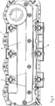
- FIG 1 a top view of a cylinder head 1 of an internal combustion engine is shown, which is operated in particular with diesel fuel.
- the cylinder head 1 of the internal combustion engine comprises a base cover 2 over the openings 3 in the area of the rocker arms, which are sealed by a separately designed cover 4.
- Figure 2 shows the top view from Figure 1 with cylinder head 1 of the internal combustion engine, which comprises a base cover 2 over the openings 3 in the area of the rocker arms, which are sealed by the separately designed cover 4 without expressly revealing this separately designed cover.
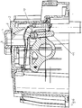
- FIG 3 a section through the cylinder head 1 with the valve open with position finder 6 is shown.
- the position finder 6 has a hexagon socket 7 with which it is placed on the lock nut 10 of the valve lash adjustment screw 11 of the rocker arm 5 through the opening 3 in the area of the rocker arm of the base cover 2.
- the position finder is shown with the valve open.
- Figure 4 shows a section through the cylinder head 1 with position finder 6.
- the position finder 6 has a hexagon socket 7 with which it is placed on the lock nut 10 of the valve lash adjustment screw 11 of the rocker arm 5 through the opening 3 in the area of the rocker arm of the base cover 2.
- the position finder is shown with the valve closed with valve overlap.
- Figure 5 is a section of the top view Figure 2 shown with position finder 6.
- the position finder 6 is placed with its hexagon socket 7 on the lock nut 10 of the valve lash adjustment screw 11 of the rocker arm 5 through the opening 3 in the area of the rocker arm of the base cover 2.
- Figure 6 discloses a section through the cylinder head 1 with a separately designed cover 4.
- the cylinder head 1 of the internal combustion engine comprises a base cover 2 over the openings 3 in the area of the rocker arms, which are sealed by a separately designed cover 4 by means of O-rings 8.
- Figure 7 shows a section through the cylinder head 1 with setting tool 12.
- the setting tool 12 has a hexagon socket 9, with which it is placed on the lock nut 10 of the valve clearance adjustment screw 11 of the rocker arm 5 through the opening 3 in the area of the rocker arm of the base cover 2.
- the adjusting tool 12 releases and / or closes the lock nut 10 of the valve lash adjustment screw 11 of the rocker arm 5 by means of a rotary movement with its hexagon socket 9.
- the setting tool 12 consists, for example, of a nut-like socket wrench insert with a hexagon socket, which is placed on the lock nut 10 of the valve lash adjustment screw 11 of the rocker arm 5 through the opening 3 in the area of the rocker arm of the base cover 2.
- the rotary angle disk 13 as in FIG Figure 8 shown, inserted with its socket wrench insert 14 into the hexagon socket of the valve lash adjustment screw 11 through the opening in the area of the rocker arm 3.
- the magnetic abutment 15 is attached to a magnetic part of the internal combustion engine located in the immediate vicinity.
- the angle disc is turned clockwise until it comes to rest, that is, the rocker arm or the valve is now free of play.
- the scale of the angle disk is now set to zero.
- the rotary angle disc is then rotated counterclockwise until the desired degree of rotation is reached. If the given The valve lash is set, the angle disk is secured against rotation, then the lock nut 10 of the valve lash adjustment screw 11 of the rocker arm 5 is tightened, for example, with a tightening torque of 20 Nm.
- This process is repeated for all valves of the internal combustion engine until the specified valve clearance is set on all valves of the internal combustion engine.
Landscapes
- Engineering & Computer Science (AREA)
- Mechanical Engineering (AREA)
- General Engineering & Computer Science (AREA)
- Chemical & Material Sciences (AREA)
- Combustion & Propulsion (AREA)
- Valve-Gear Or Valve Arrangements (AREA)
- Cylinder Crankcases Of Internal Combustion Engines (AREA)
Description
- Eine Ventilsteuerung oder ein Ventiltrieb ist ein Mechanismus, der bei einem Hubkolbenmotor die Ventile und damit den Ladungswechsel durch Öffnen und Schließen der Lufteinlass- und Abgasaustrittskanäle steuert. Er wird in fast allen Viertaktmotoren verwendet. Aus der
JPS5984204U JPS53130306U - In der Regel wird ein Ventil von einer Nockenwelle über einen Stößel, Schlepphebel oder Kipphebel geöffnet. Geschlossen werden Ventile durch Schraubenfedern, selten durch Drehstabfedern, Gasfedern oder über einen Schließnocken zwangsgesteuert. Die Nockenwelle wird von der Kurbelwelle angetrieben, bei Viertaktmotoren mit einer Übersetzung von 2:1. Die Nockenwelle hat somit die halbe Drehzahl der Kurbelwelle.
- Im Betrieb werden Ventile während jeder Sekunde mehrmals geöffnet und geschlossen, also beschleunigt und wieder zum Stillstand gebracht. Die Bewegungen der Ventile und des Kolbens im Zylinder müssen genau aufeinander abgestimmt sein,
- Vor der Einstellung der Ventile steht die Öffnung des Zylinderkopfes. Hier gibt es meist Deckel, die von Schrauben oder sogar Klemmmechanismen gehalten werden. Ventile und/oder deren Antrieb können auch durch größere, abschraubbare Gewindedeckel erreichbar sein. Wichtig ist hierbei, welches Ventil bei welcher Stellung des Motors einzustellen ist. Keine Probleme gibt es, wenn die Nockenwelle ebenfalls freiliegt. Dann dreht man mit geeigneten Mitteln so lange an der Kurbelwelle, bis der jeweilige Nocken etwa 180° verdreht zur höchsten Ventilerhebung steht.
- Alle Teile des Motors dehnen sich im Betrieb je nach Temperatursteigerung und je nach Werkstoff mehr oder weniger aus. Außerdem treten an den Übertragungsteilen der Motorsteuerung Längenänderungen durch Verschleiß auf. Damit die Einlass- und Auslassventile bei allen Betriebszuständen schließen können, wird zwischen Ventil und Kipphebel Spiel vorgesehen. Das Spiel ist vom Motorenhersteller genau vorgeschrieben und muss mit Rücksicht auf den durch das dauernde Aufschlagen des Kipphebels auf den Ventilschaft und des Ventiltellerkegels auf den Ventilsitz auftretenden Verschleiß bei warmem oder kaltem Motor (je nachdem, wie es der Motorhersteller vorschreibt) in gewissen Zeitabständen nachgestellt werden.
- Das Ventilspiel muss genau eingehalten und kontrolliert werden.
- Zu kleines Ventilspiel bedeutet, dass die Ventile bei betriebswarmem Motor nicht ganz schließen könnten. Dadurch entsteht Kompressionsverlust. Das hat zur Folge, dass die heißen Verbrennungsgase zwischen Ventil und Ventilsitzring hindurch blasen. Dieser Vorgang führt dazu, dass der Ventilsitz und das Ventil verbrennen. Ein großer Leistungsabfall ist die Folge.
- Zu großes Ventilspiel kann zur Folge haben, dass die Ventile zu früh schließen und sich dadurch die unter Druck stehenden Verbrennungsgase nicht rechtzeitig entspannen, was eine ungenügende Spülung des Zylinders von den Abgasen und schlechte Neubefüllung mit Frischgasen zur Folge hat. Dies hat ebenfalls sehr starken Leistungsverlust zur Folge.
- Um ein sicheres Schließen des Ventils unter allen Betriebsbedingungen sicherzustellen, wird ein Ventilspiel vorgesehen - ein kleiner Abstand irgendwo im Ventiltrieb. Dieser Abstand verringert sich mit Erreichen der Betriebstemperatur, darf aber nicht Null werden. Zu großes Spiel bewirkt wiederum Leistungsverlust, starke Geräuschentwicklung und erhöhten Verschleiß des Ventiltriebs.
- Die Hersteller geben daher einen Bereich für das Ventilspiel an, in der Größenordnung einiger Hundertstel- bis Zehntelmillimeter, meist bezogen auf den kalten Motor. Das Ventilspiel soll in regelmäßigen Wartungsintervallen - etwa nach Kilometerleistung oder nach Betriebsstunden - kontrolliert und nötigenfalls nachgestellt werden, falls der Motor keinen automatischen Ventilspiel-Ausgleich hat.
- Das Spiel wird meist mit Fühlerblattlehren gemessen und dann je nach Bauart unterschiedlich eingestellt: Bei Kipphebeln, die von Stoßstangen betätigt werden, befindet sich in den Hebeln häufig eine gekonterte Schraube, an der die Einstellung vorgenommen werden kann. Bei anderen Konstruktionen wird der Drehpunkt der Hebel verstellt. Tassenstößel haben dagegen gehärtete Einlegeplättchen ("Shims"), die zwischen Stößel und Nocken bzw. Stößel und Ventilschaft platziert werden. Diese sind in feinen Abstufungen der Dicke erhältlich und werden bei notwendiger Korrektur ausgetauscht.
- Genauso wichtig wie die Ausbildung des Verbrennungsraumes für den Ablauf der Verbrennung ist die Steuerung der während des Ansaugtaktes in den Arbeitszylinder einströmenden Frischluftsäule und der während des Auspufftaktes aus dem Arbeitszylinder ausströmenden verbrannten Gase.
- Wir wollen uns zunächst vor Augen führen, welche Teile des Motors zum Öffnen und Schließen der Ein und Auslassventile gehören und wie sie betätigt werden.
- Auf der Kurbelwelle ist ein Zahnrad aufgeschrumpft oder aufgekeilt, welches das auf der Nockenwelle sitzende Steuerrad antreibt. Da die Ventile durch die gleichmäßig auf der Nockenwelle verteilten Nocken (1 Nocken für jedes Ventil) im Verlauf eines Arbeitsspieles (Ansaugen, Verdichten, Arbeiten, Ausstoßen, das sind zwei Kurbelwellenumdrehungen) je einmal geöffnet und geschlossen werden, muss die Drehzahl der Kurbelwelle zur Drehzahl der Nockenwelle im Verhältnis 2:1 untersetzt werden, d. h., Durchmesser und Zähnezahl des Kurbel- und Nockenwellenzahnrades müssen so abgestimmt sein, dass sich die Nockenwelle bei zwei Umdrehungen der Kurbelwelle nur einmal dreht.
- Geöffnet werden die Ventile bei Motoren mit hängenden Ventilen durch das Auflaufen des Nockens gegen den Stößel, der seinerseits über die Stößelstange den Kipphebel betätigt, mit dem das Ventil geöffnet wird. Läuft der Nocken vom Stößel wieder ab, so drückt die zwischen den mit konischen Halbkeilen gesicherten Ventilteller und den Zylinderkopf gepresste Ventilfeder das Ventil auf den Ventilsitz.
- Beim Einstellen des Ventilspiels muss man die Einstellvorschrift des Herstellers beachten, ob er die Einstellung bei kaltem oder warmem Motor vorschreibt.
- Das Ventilspiel wird an den Kipphebeleinstellschrauben folgendermaßen verstellt:
- Die Sechskantmuttern (b) an den Kipphebeleinstellschrauben der beiden einzustellenden Ventile lösen.
- Fühlerlehre von der vorgeschriebenen Dicke zwischen Kipphebel und Ventilschaft (e) schieben.
- Die Kipphebelleinstellschraube (a) soweit lösen/anziehen, bis sich die Fühlerlehre saugend herausziehen und wieder hineinschieben lässt.
- Die Einstellschraube festhalten und die Sechskantmutter mit einem Schraubenschlüssel anziehen.
- Abschließend muss das Spiel nochmals kontrolliert werden. Lässt sich die Fühlerlehre nicht saugend einschieben und herausziehen, hat sich wahrscheinlich beim Anziehen der Kontermutter die Einstellschraube verdreht. In diesem Fall muss das Einstellen nochmals vorgenommen werden.
- Zum Einstellen des Ventilspiels müssen beide Ventile des entsprechenden Zylinders geschlossen sein. Diesen Zustand erhalten die Ventile, wenn sich der jeweilige Zylinder am Ende des Verdichtungstaktes oder am Anfang des Arbeitstaktes befindet. Um diese Ventilstellung zu erreichen, dreht man den Motor so lange von Hand durch, bis sich beide Ventile gleichzeitig bewegen (Ventilüberschneidung). Wenn dies der Fall ist, muss der Motor weitere 360° Grad weitergedreht werden (eine Kurbelwellenumdrehung). Nun müssen die Ventile geschlossen sein. Dies lässt sich überprüfen, indem man die Stößelstange (c) von Hand drehen oder den Kipphebel minimal bewegen kann.
- Bei Mehrzylindermotoren muss das Spiel an jedem einzelnen Zylinder eingestellt werden.
- Bei einem 4-Zylinderreihenmotor wird Zylinder 1 eingestellt, wenn sich Zylinder 4 in der Ventilüberschneidung (VÜ) befindet (Zylinder 2 einstellbar bei VÜ von Zylinder 3) und umgekehrt (Zyl. 1 VÜ ZylA einstellbar/Zyl. 2 VÜ Zyl. 3 einstellbar.)
- Bei der Ventilspiel-Einstellung kommt es darauf an, dass weder der zuständige Nocken noch ein evtl. vorhandener Ausläufer davon das Ventil betätigt. Deshalb gibt es bei nicht sichtbarer Nockenwelle in der Regel verbindliche Regeln für die Stellung des Motors. Wer diese Regeln nicht hat, kann einfach den Motor nach der größten Erhebung des Ventils 180°, bezogen auf die Nockenwelle, oder 360°, bezogen auf die Kurbelwelle, weiter drehen. Ist die richtige Stellung gefunden, wird die oben abgebildete Fühlerlehre gebraucht. Diese ist in der Regel bei einem Messbereich von 0,05 - 0,5 mm und einer Stufung von 0,05 mm ausreichend. Wenn man jetzt die vorgegebene Stelle im Ventiltrieb gefunden hat, an der das Spiel gemessen werden kann, zieht man das entsprechende Blatt mit dem Einstellwert durch. Das kann zwischen Nocken und Tassenstößel oder zwischen Schlepp-/Kipphebel und Nocken sein.
- Zur Beurteilung, ob der Einstellwert exakt erreicht wurde, ist eine gewisse Erfahrung mit der Ventilspiel-Einstellung nötig. Das Blatt der Fühlerlehre darf nicht zu leicht- und auch nicht zu schwergängig durchzuziehen sein.
- Es gibt kaum größere Unterschiede als bei der technischen Umsetzung der Einstellmöglichkeit. Weithin bekannt sind wohl Schlitzkopf- oder Inbusschrauben z. B. an Kipphebeln, mit Gabelschlüssel verdrehbare Umlenkpunkte von Schlepphebeln und kleine Plättchen, die in Tassenstößel eingelegt werden. Aber auch selbstsichernde Inbusschrauben in Tassenstößeln u. a. hat es in der Geschichte der Ventileinstellung gegeben. Die höchsten Anforderungen stellt wohl die Desmodromische Ventilsteuerung. Weniger hohe stellt offenbar der Motor einer Diesellok (3. Bild oben). Hier werden je zwei Ventile durch einen Nocken betätigt. Durch nur eine Einstellschraube bleibt an einem der beiden Ventile ein etwas größeres Spiel erhalten.
- Das Einstellen des Ventilspieles im Ventiltrieb einer Brennkraftmaschine ist unter anderem aus der
DE 36 35 929 A1 bekannt. Bei dieser Erfindung wird bei einem Verfahren zwischen Ventil und Betätigungsglied (Kipphebel) ein Abstandsstück eingeschoben, dessen Höhe gleich ist der Summe von Ventilspiel und einem Vorhaltebetrag, und anschließend das Ventil über die Verstelleinrichtung um den Vorhaltebetrag vom Ventilsitz angehoben. Bei diesem Verfahren können sich Einstellfehler dadurch ergeben, dass bei Beginn des Einstellvorganges das einzustellende Ventil nicht auf dem Ventilsitz aufsitzt. - Es ist eine Totpunktmarkierung bekannt,
DE-OS 28 43 039 , bei der eine Markierung auf der Schwungradstirnseite durch eine Öffnung in der Stirnseite des Schwungradgehäuses mittels Taststift zugänglich ist. Durch eine zweite Öffnung kann ein Wegmessgerät auf der Planfläche des Schwungrades angesetzt werden, das den bei Drehung zurückgelegten Weg erfasst und anzeigt. Damit ist ein zurückgelegter Drehwinkel, ausgehend vom oberen Totpunkt, erfassbar. Nachteilig ist hierbei, dass die gemessene Wegstrecke in einen Drehwinkel der Kurbelwelle umgerechnet werden muss und die mögliche Ungenauigkeit der Reibmitnahme des Wegmessgerätes durch die Schwungradstirnfläche; denn der Vorgang kann innerhalb des Gehäuses nicht beobachtet werden. Ferner sind bei den meisten Motoren diese angegebenen Schwungradflächen zum Ansetzen des Wegmessrades nicht zugänglich, weil angebaute Kupplungs- und Getriebegehäuse den Zugang versperren. Meist fehlt bei Motoren auch eine Durchdrehmöglichkeit von Hand, weil bei angekoppelter Arbeitsmaschine die Zugänglichkeit versperrt ist und beim möglichen Durchdrehen am vorderen Kurbelwellenende die Trägheit der angekoppelten Arbeitsmaschine mit überwunden werden muss. - Bekannte, gattungsgemäße Prüfeinrichtungen weisen bereits folgende Merkmale auf:
- Antrieb von mindestens einem Ventil über eine Nockenwelle,
- mechanische Einstellbarkeit des Ventilspieles,
- Tassenstößel als Nockenfolger mit einem direkten Kraftschluss gegenüber dem Ventil, wobei anstelle eines Tassenstößels auch Schlepp- oder Kipphebel bei dann auf das Ventil auftretenden Seitenkräften einsetzbar sind,
- Einstellbarkeit der Ventilfederkräfte durch eine Austauschmöglichkeit für die Ventilfedern oder einen Einsatz unterschiedlicher Unterlegscheiben bei der Abstützung einer Ventilfeder,
- Austauschbarkeit und Positionierbarkeit gegenüber der Ventilführung der Ventilsitzringträger mit darin eingepressten Ventilsitzringen,
- Einsatz einer Induktionsanlage als Wärmequelle zum Erwärmen des Ventiles, wobei als Wärmequelle unter anderem auch Brenner, Heißluftgebläse oder dergleichen möglich sind,
- Messbarkeit der Ventilsitzringtemperatur über Thermoelemente,
- Kühlbarkeit der Prüfeinrichtung durch Kühlwasser, Öl, Luft oder andere Kühlmedien.
- Die Erfindung beschäftigt sich mit dem Problem, eine gattungsgemäße Prüfeinrichtung funktionell zu verbessern.
- Die Erfindung betrifft eine Brennkraftmaschine gemäß Anspruch 1 und ein Verfahren gemäß Anspruch 6.
- Vorteilhafte und zweckmäßige Ausgestaltungen dieser erfindungsgemäßen Lösung sind Gegenstand der Unteransprüche.
- Die Erfindung beruht auf folgenden allgemeinen Überlegungen:
- Zur Überwindung eines relativ groß eingestellten Ventilspiels und zur Erzielung geringer Stoßimpulse zwischen dem Nocken und einem das Ventil kontaktierenden Nockenfolger sowie eines geringen Verschleißes zwischen Nocken und Nockenfolger ist an einem Antriebs-Nocken - falls ein solcher eingesetzt ist - eine lange, flache Anlauframpe vorgesehen. Die Höhe dieser Rampe richtet sich nach dem maximalen Ventilspiel. Die Länge der Rampe erfasst vorzugsweise einen Nockenwinkelbereich von 50 deg. bis 130.
- Auf den langen, flachen Anlauframpenbereich eines Nockens als Ventilantrieb folgt eine hohe Steigung der Nockenerhebung bis zu einer maximalen Höhe der Nockenerhebung, die als solche möglichst gering gewählt wird, eine lange Rastphase des Ventils bei maximalem Ventilhub ermöglicht eine hohe Verweilzeit des Ventiltellers in einer für einen bestmöglichen Wärmeaustausch gegenüber der Wärmequelle möglichst gering beabstandeten Position. Die Länge der Rastphase liegt vorzugsweise in einem Nockenwinkelbereich zwischen 20 deg. und 60, die Schließflanke des Nockens ist so ausgebildet, dass eine gewünscht hohe Aufsetzgeschwindigkeit des Ventiltellers auf den Ventilsitzring erreichbar ist. Die gewünschte Aufsetzgeschwindigkeit wird über die Drehzahl des den Nocken antreibenden Antriebsmotors eingestellt.
- Die Erfindung wird nachfolgend anhand der Figuren erläutert. Die Erfindung ist nicht auf den Gegenstand der Figuren beschränkt. Es zeigen schematisch:
- Figur 1
- eine Draufsicht auf einen Zylinderkopfdeckel,
- Figur 2
- die Draufsicht aus
Figur 1 ohne separat ausgebildeten Deckel, - Figur 3
- einen Schnitt durch den Zylinderkopf bei geöffnetem Ventil mit Positionsfinder,
- Figur 4
- den Schnitt aus
Figur 3 bei geschlossenem Ventil mit Positionsfinder, - Figur 5
- einen Ausschnitt der Draufsicht aus
Figur 2 mit Positionsfinder, - Figur 6
- einen Schnitt durch den Zylinderkopf mit separat ausgebildetem Deckel,
- Figur 7
- den Schnitt aus
Figur 6 bei geschlossenem Ventil mit Einstellwerkzeug, - Figur 8
- Drehwinkelscheibe des Ventilspieleinstellwerkzeugs.
- In
Figur 1 wird eine Draufsicht auf einen Zylinderkopf 1 einer Brennkraftmaschine dargestellt, die insbesondere mit Dieselkraftstoff betrieben wird. Der Zylinderkopf 1 der Brennkraftmaschine umfasst einen Grunddeckel 2 über den Öffnungen 3 im Bereich der Kipphebel, die von einem separat ausgebildeten Deckel 4 abgedichtet werden. -
Figur 2 zeigt die Draufsicht ausFigur 1 mit Zylinderkopf 1 der Brennkraftmaschine, die einen Grunddeckel 2 über den Öffnungen 3 im Bereich der Kipphebel umfasst, die von dem separat ausgebildeten Deckel 4 abgedichtet werden, ohne diesen separat ausgebildeten Deckel ausdrücklich zu offenbaren. - In
Figur 3 wird ein Schnitt durch den Zylinderkopf 1 bei geöffnetem Ventil mit Positionsfinder 6 dargestellt. Der Positionsfinder 6 weist einen Innensechskant 7 auf, mit dem er auf die Kontermutter 10 der Ventilspieleinstellschraube 11 des Kipphebels 5 durch die Öffnung 3 im Bereich der Kipphebel des Grunddeckels 2 aufgesetzt wird. Der Positionsfinder wird bei geöffnetem Ventil gezeigt. -
Figur 4 zeigt einen Schnitt durch den Zylinderkopf 1 mit Positionsfinder 6. Der Positionsfinder 6 weist einen Innensechskant 7 auf, mit dem er auf die Kontermutter 10 der Ventilspieleinstellschraube 11 des Kipphebels 5 durch die Öffnung 3 im Bereich der Kipphebel des Grunddeckels 2 aufgesetzt ist. Der Positionsfinder wird bei geschlossenem Ventil mit Ventilüberschneidung gezeigt. - In
Figur 5 wird ein Ausschnitt der Draufsicht ausFigur 2 mit Positionsfinder 6 dargestellt. Der Positionsfinder 6 ist mit seinem Innensechskant 7 auf die Kontermutter 10 der Ventilspieleinstellschraube 11 des Kipphebels 5 durch die Öffnung 3 im Bereich der Kipphebel des Grunddeckels 2 aufgesetzt. -
Figur 6 offenbart einen Schnitt durch den Zylinderkopf 1 mit separat ausgebildetem Deckel 4. Der Zylinderkopf 1 der Brennkraftmaschine umfasst einen Grunddeckel 2 über den Öffnungen 3 im Bereich der Kipphebel, die von einem separat ausgebildeten Deckel 4 mittels Runddichtringen 8 abgedichtet werden. -
Figur 7 zeigt einen Schnitt durch den Zylinderkopf 1 mit Einstellwerkzeug 12. Das Einstellwerkzeug 12 weist einen Innensechskant 9 auf, mit dem er auf die Kontermutter 10 der Ventilspieleinstellschraube 11 des Kipphebels 5 durch die Öffnung 3 im Bereich der Kipphebel des Grunddeckels 2 aufgesetzt ist. Das Einstellwerkzeug 12 löst und/oder schließt mittels einer Drehbewegung mit seinem Innensechskant 9 die Kontermutter 10 der Ventilspieleinstellschraube 11 des Kipphebels 5. - Das Einstellwerkzeug 12 besteht beispielsweise aus einem nussartigen Steckschlüsseleinsatz mit Innensechskant, der auf die Kontermutter 10 der Ventilspieleinstellschraube 11 des Kipphebels 5 durch die Öffnung 3 im Bereich der Kipphebel des Grunddeckels 2 aufgesetzt ist. Nachdem die Kontermutter 10 der Ventilspieleinstellschraube 11 des Kipphebels 5 gelöst ist wird die Drehwinkelscheibe 13, wie in
Figur 8 dargestellt, mit ihrem Steckschlüsseleinsatz 14 in den Innensechskant der Ventilspieleinstellschraube 11 durch die Öffnung im Bereich der Kipphebel 3 hindurch eingesetzt. Das magnetische Widerlager 15 wird zur Erhöhung der Lagestabilität an einem im näheren Umfeld befindlichen magnetischen Teil der Brennkraftmaschine befestigt. Anschließend wird die Drehwinkelscheibe im Uhrzeigersinn bis zur Anlage gedreht, das heißt, der Kipphebel bzw. das Ventil ist nun spielfrei. Die Skala der Drehwinkelscheibe wird nun auf Null gestellt. Anschließend wird die Drehwinkelscheibe entgegen des Uhrzeigersinns bis zum Erreichen des gewünschten Drehwinkelgrades gedreht. Wenn das vorgegebene Ventilspiel eingestellt ist wird die Drehwinkelscheibe gegen Verdrehen gesichert, anschließend wird die Kontermutter 10 der Ventilspieleinstellschraube 11 des Kipphebels 5 beispielsweise mit einem Anziehmoment von 20 Nm angezogen. - Dieser Vorgang wird bei allen Ventilen der Brennkraftmaschine wiederholt, bis das vorgegebene Ventilspiel an allen Ventilen der Brennkraftmaschine eingestellt ist.
-
- 1
- Zylinderkopf
- 2
- Grunddeckel
- 3
- Öffnung im Bereich der Kipphebel
- 4
- separat ausgebildeter Deckel
- 5
- Kipphebel
- 6
- Positionsfinder
- 7
- Innensechskant des Positionsfinders
- 8
- Runddichtring
- 9
- Innensechskant der Einstellschraube
- 10
- Kontermutter
- 11
- Ventilspieleinstellschraube
- 12
- Einstellwerkzeug
- 13
- Drehwinkelscheibe
- 14
- Steckschlüsseleinsatz
- 15
- magnetisches Widerlager
Claims (6)
- Brennkraftmaschine mit einem Kurbelgehäuse und mit mindestens einem Zylinder und Zylinderkopf, sowie mit einer im Kurbelgehäuse angeordneten Kurbelwelle, über die im Zylinderkopf angeordnete Nockenwellen angetrieben bzw. gesteuert sind, sowie mit einem Zylinderkopfdeckel, der im Wesentlichen den Zylinderkopf über dessen gesamte Breite und Länge abschließt, wobei der Zylinderkopfdeckel im eingebauten Zustand der Brennkraftmaschine einen Grunddeckel (2) mit wenigstens einer Öffnung pro Ventil aufweist, die durch einen separat ausgebildeten Deckel (4) verschließbar ausgebildet ist und wobei die Ventile mittels Kipphebel (5) angesteuert sind, wobei die Öffnung (3) im Bereich der Kipphebel angeordnet ist, wobei sie wenigstens einen Positionsfinder (6) aufweist, dadurch gekennzeichnet, dass sie ein Einstellwerkzeug (12) aufweist, das eine montier- bzw. demontierbare Drehwinkelscheibe (13) und ein magnetisches Widerlager aufweist.
- Brennkraftmaschine nach Anspruch 1,
dadurch gekennzeichnet, dass der zum Verschließen der Öffnung (3) vorgesehene separat ausgebildete Deckel (4) mit dem Grunddeckel verbindbar angeordnet ist. - Brennkraftmaschine nach einem oder mehreren der vorgenannten Ansprüche, dadurch gekennzeichnet, dass sie je Kipphebel einen montier- bzw. demontierbaren Positionsfinder (6) aufweist.
- Brennkraftmaschine nach einem oder mehreren der vorgenannten Ansprüche,
dadurch gekennzeichnet, dass jeder Kipphebel (5) wenigstens eine Ventilspieleinstellschraube (11) aufweist, die mittels Kontermutter (10) gesichert ist. - Brennkraftmaschine nach einem oder mehreren der vorgenannten Ansprüche,
dadurch gekennzeichnet, dass das Ventilspiel in einem Bereich von 0,25 bis 0,35 mm einstellbar ist. - Verfahren zum Einstellen des Ventilspiels,
dadurch gekennzeichnet, dass eine Brennkraftmaschine nach einem oder mehreren der vorgenannten Ansprüche zum Einsatz kommt.
Applications Claiming Priority (1)
| Application Number | Priority Date | Filing Date | Title |
|---|---|---|---|
| DE102015000369.0A DE102015000369A1 (de) | 2015-01-20 | 2015-01-20 | Verfahren und Vorrichtung zum Einstellen eines Ventilspieles |
Publications (3)
| Publication Number | Publication Date |
|---|---|
| EP3048273A2 EP3048273A2 (de) | 2016-07-27 |
| EP3048273A3 EP3048273A3 (de) | 2016-08-10 |
| EP3048273B1 true EP3048273B1 (de) | 2020-12-09 |
Family
ID=55168124
Family Applications (1)
| Application Number | Title | Priority Date | Filing Date |
|---|---|---|---|
| EP16000082.4A Active EP3048273B1 (de) | 2015-01-20 | 2016-01-14 | Brennkraftmaschine und verfahren zum einstellen des ventilspieles |
Country Status (2)
| Country | Link |
|---|---|
| EP (1) | EP3048273B1 (de) |
| DE (1) | DE102015000369A1 (de) |
Citations (2)
| Publication number | Priority date | Publication date | Assignee | Title |
|---|---|---|---|---|
| CH608874A5 (en) * | 1976-11-16 | 1979-01-31 | Meier Karl Tekusa | Stand having three hinges |
| JPS5984204U (ja) * | 1982-11-29 | 1984-06-07 | 日産自動車株式会社 | バルブクリアランス調整工具 |
Family Cites Families (10)
| Publication number | Priority date | Publication date | Assignee | Title |
|---|---|---|---|---|
| JPS6016757Y2 (ja) * | 1977-03-22 | 1985-05-24 | 川崎重工業株式会社 | オ−バ−ヘツドカム式エンジンのバルブクリアヲンス調整装置 |
| DE2843039A1 (de) | 1978-10-03 | 1980-04-17 | Kloeckner Humboldt Deutz Ag | Verfahren zum einstellen von hilfsaggregaten bei brennkraftmaschinen |
| DE3635929A1 (de) | 1986-10-22 | 1988-05-05 | Daimler Benz Ag | Verfahren zum einstellen des ventilspiels eines ventils in einer brennkraftmaschine |
| JP2786699B2 (ja) * | 1989-11-29 | 1998-08-13 | ヤマハ発動機株式会社 | Sohcエンジンの動弁装置 |
| US5095860A (en) * | 1991-06-24 | 1992-03-17 | Newell Bobby T | Engine valve cover apparatus |
| US6345436B1 (en) * | 1999-06-22 | 2002-02-12 | Ernest Richardson Codrington | Combination torque tool and method of adjusting valves and injectors |
| JP4026719B2 (ja) * | 2005-06-28 | 2007-12-26 | 本田技研工業株式会社 | タペットクリアランス調整装置 |
| JP4827902B2 (ja) * | 2008-09-08 | 2011-11-30 | 平田機工株式会社 | バルブクリアランスの測定調整方法および測定調整装置 |
| US8056522B1 (en) * | 2009-08-06 | 2011-11-15 | Gary Mikle Carter | Automotive valve cover |
| US9091205B2 (en) * | 2012-04-27 | 2015-07-28 | Ruben Santos | Rocker arm accessibility cover assembly |
-
2015
- 2015-01-20 DE DE102015000369.0A patent/DE102015000369A1/de not_active Withdrawn
-
2016
- 2016-01-14 EP EP16000082.4A patent/EP3048273B1/de active Active
Patent Citations (2)
| Publication number | Priority date | Publication date | Assignee | Title |
|---|---|---|---|---|
| CH608874A5 (en) * | 1976-11-16 | 1979-01-31 | Meier Karl Tekusa | Stand having three hinges |
| JPS5984204U (ja) * | 1982-11-29 | 1984-06-07 | 日産自動車株式会社 | バルブクリアランス調整工具 |
Also Published As
| Publication number | Publication date |
|---|---|
| EP3048273A3 (de) | 2016-08-10 |
| DE102015000369A1 (de) | 2016-07-21 |
| EP3048273A2 (de) | 2016-07-27 |
Similar Documents
| Publication | Publication Date | Title |
|---|---|---|
| DE60317854T2 (de) | Ventilspielausgleichswerkzeug und -methode | |
| DE60101985T2 (de) | Verfahren zum automatischen Einstellen von Ventilspielen in einem Verbrennungsmotor | |
| DE112018000752T5 (de) | Intelligenter Greifer für einen Hydraulischen Drehmomentwandler mit einer automatischen Zahnanpassungsfunktion | |
| DE60109883T2 (de) | Ventilaktuator mit einem Spielausgleichselement | |
| DE60201250T2 (de) | Verfahren zur Einstellung von Ventilspielen und Vorrichtung zur Durchführung des Verfahrens | |
| DE10261304B4 (de) | Ventilhubvorrichtung zur variablen Ventilsteuerung der Gaswechselventile einer Verbrennungskraftmaschine | |
| DE3146875C2 (de) | ||
| DE60319299T2 (de) | Verfahren und Vorrichtung zur Steuerung einer Brennkraftmaschine | |
| DE102010026393B4 (de) | Kraftstoffpumpen-Antriebssystem | |
| DE3003569A1 (de) | Vorrichtung zur hydraulischen verstellung des ventilhubes von gaswechselventilen einer hubkolbenbrennkraftmaschine | |
| DE10307307A1 (de) | Verfahren zum Steuern einer Brennkraftmaschine | |
| EP3048273A2 (de) | Verfahren und vorrichtung zum einstellen des ventilspieles | |
| EP1375843B1 (de) | Brennkraftmaschine mit innerer Verbrennung | |
| EP1608852B1 (de) | Vorrichtung zur variablen bet tigung der gaswechselventile v on verbrennungsmotoren und verfahren zum betreiben einer derartigen vorrichtung | |
| DE10312959A1 (de) | Vorrichtung zur variablen Betätigung der Gaswechselventile von Verbrennungsmotoren und Verfahren zum Betreiben einer derartigen Vorrichtung | |
| EP1680577A1 (de) | Ventiltrieb einer brennkraftmaschine mit mindestens einer nockenwelle | |
| DE4300487C2 (de) | Vorrichtung zur Ventilspieleinstellung in variablen Ventilsteuerungen von Brennkraftmaschinen | |
| DE102016006475A1 (de) | Verfahren zum Betreiben einer Brennkraftmaschine sowie entsprechende Brennkraftmaschine | |
| DE10312962A1 (de) | Vorrichtung zur Betätigung von Ladungswechselventilen in Hubkolbenmotoren | |
| WO2015188907A1 (de) | Verfahren zum betreiben einer brennkraftmaschine sowie entsprechende brennkraftmaschine | |
| DE20316281U1 (de) | Vorrichtung zur Einstellung und Arretierung von Nockenwellen | |
| DE3512035A1 (de) | Einrichtung zur ventilbetaetigung | |
| DE102021124416A1 (de) | Verfahren zum Betreiben einer Brennkraftmaschine sowie entsprechende Brennkraftmaschine | |
| DE608400C (de) | Einrichtung zum Erleichtern des Anlassens von mit hoher Verdichtung arbeitenden Brennkraft-, insbesondere Dieselmaschinen | |
| DE3436629A1 (de) | Nockenwellensteuerung |
Legal Events
| Date | Code | Title | Description |
|---|---|---|---|
| PUAI | Public reference made under article 153(3) epc to a published international application that has entered the european phase |
Free format text: ORIGINAL CODE: 0009012 |
|
| PUAL | Search report despatched |
Free format text: ORIGINAL CODE: 0009013 |
|
| AK | Designated contracting states |
Kind code of ref document: A2 Designated state(s): AL AT BE BG CH CY CZ DE DK EE ES FI FR GB GR HR HU IE IS IT LI LT LU LV MC MK MT NL NO PL PT RO RS SE SI SK SM TR |
|
| AX | Request for extension of the european patent |
Extension state: BA ME |
|
| AK | Designated contracting states |
Kind code of ref document: A3 Designated state(s): AL AT BE BG CH CY CZ DE DK EE ES FI FR GB GR HR HU IE IS IT LI LT LU LV MC MK MT NL NO PL PT RO RS SE SI SK SM TR |
|
| AX | Request for extension of the european patent |
Extension state: BA ME |
|
| RIC1 | Information provided on ipc code assigned before grant |
Ipc: F02F 7/00 20060101ALI20160701BHEP Ipc: F01L 1/18 20060101ALI20160701BHEP Ipc: F01L 1/20 20060101AFI20160701BHEP Ipc: F02B 77/08 20060101ALI20160701BHEP |
|
| STAA | Information on the status of an ep patent application or granted ep patent |
Free format text: STATUS: REQUEST FOR EXAMINATION WAS MADE |
|
| 17P | Request for examination filed |
Effective date: 20170120 |
|
| RBV | Designated contracting states (corrected) |
Designated state(s): AL AT BE BG CH CY CZ DE DK EE ES FI FR GB GR HR HU IE IS IT LI LT LU LV MC MK MT NL NO PL PT RO RS SE SI SK SM TR |
|
| STAA | Information on the status of an ep patent application or granted ep patent |
Free format text: STATUS: EXAMINATION IS IN PROGRESS |
|
| 17Q | First examination report despatched |
Effective date: 20170530 |
|
| GRAP | Despatch of communication of intention to grant a patent |
Free format text: ORIGINAL CODE: EPIDOSNIGR1 |
|
| STAA | Information on the status of an ep patent application or granted ep patent |
Free format text: STATUS: GRANT OF PATENT IS INTENDED |
|
| INTG | Intention to grant announced |
Effective date: 20200706 |
|
| GRAS | Grant fee paid |
Free format text: ORIGINAL CODE: EPIDOSNIGR3 |
|
| GRAA | (expected) grant |
Free format text: ORIGINAL CODE: 0009210 |
|
| STAA | Information on the status of an ep patent application or granted ep patent |
Free format text: STATUS: THE PATENT HAS BEEN GRANTED |
|
| AK | Designated contracting states |
Kind code of ref document: B1 Designated state(s): AL AT BE BG CH CY CZ DE DK EE ES FI FR GB GR HR HU IE IS IT LI LT LU LV MC MK MT NL NO PL PT RO RS SE SI SK SM TR |
|
| REG | Reference to a national code |
Ref country code: GB Ref legal event code: FG4D Free format text: NOT ENGLISH |
|
| REG | Reference to a national code |
Ref country code: AT Ref legal event code: REF Ref document number: 1343667 Country of ref document: AT Kind code of ref document: T Effective date: 20201215 Ref country code: CH Ref legal event code: EP |
|
| REG | Reference to a national code |
Ref country code: DE Ref legal event code: R096 Ref document number: 502016011886 Country of ref document: DE |
|
| REG | Reference to a national code |
Ref country code: IE Ref legal event code: FG4D Free format text: LANGUAGE OF EP DOCUMENT: GERMAN |
|
| REG | Reference to a national code |
Ref country code: SE Ref legal event code: TRGR |
|
| PG25 | Lapsed in a contracting state [announced via postgrant information from national office to epo] |
Ref country code: RS Free format text: LAPSE BECAUSE OF FAILURE TO SUBMIT A TRANSLATION OF THE DESCRIPTION OR TO PAY THE FEE WITHIN THE PRESCRIBED TIME-LIMIT Effective date: 20201209 Ref country code: FI Free format text: LAPSE BECAUSE OF FAILURE TO SUBMIT A TRANSLATION OF THE DESCRIPTION OR TO PAY THE FEE WITHIN THE PRESCRIBED TIME-LIMIT Effective date: 20201209 Ref country code: NO Free format text: LAPSE BECAUSE OF FAILURE TO SUBMIT A TRANSLATION OF THE DESCRIPTION OR TO PAY THE FEE WITHIN THE PRESCRIBED TIME-LIMIT Effective date: 20210309 Ref country code: GR Free format text: LAPSE BECAUSE OF FAILURE TO SUBMIT A TRANSLATION OF THE DESCRIPTION OR TO PAY THE FEE WITHIN THE PRESCRIBED TIME-LIMIT Effective date: 20210310 |
|
| PG25 | Lapsed in a contracting state [announced via postgrant information from national office to epo] |
Ref country code: BG Free format text: LAPSE BECAUSE OF FAILURE TO SUBMIT A TRANSLATION OF THE DESCRIPTION OR TO PAY THE FEE WITHIN THE PRESCRIBED TIME-LIMIT Effective date: 20210309 Ref country code: LV Free format text: LAPSE BECAUSE OF FAILURE TO SUBMIT A TRANSLATION OF THE DESCRIPTION OR TO PAY THE FEE WITHIN THE PRESCRIBED TIME-LIMIT Effective date: 20201209 |
|
| REG | Reference to a national code |
Ref country code: NL Ref legal event code: MP Effective date: 20201209 |
|
| PG25 | Lapsed in a contracting state [announced via postgrant information from national office to epo] |
Ref country code: HR Free format text: LAPSE BECAUSE OF FAILURE TO SUBMIT A TRANSLATION OF THE DESCRIPTION OR TO PAY THE FEE WITHIN THE PRESCRIBED TIME-LIMIT Effective date: 20201209 Ref country code: NL Free format text: LAPSE BECAUSE OF FAILURE TO SUBMIT A TRANSLATION OF THE DESCRIPTION OR TO PAY THE FEE WITHIN THE PRESCRIBED TIME-LIMIT Effective date: 20201209 |
|
| REG | Reference to a national code |
Ref country code: LT Ref legal event code: MG9D |
|
| PG25 | Lapsed in a contracting state [announced via postgrant information from national office to epo] |
Ref country code: RO Free format text: LAPSE BECAUSE OF FAILURE TO SUBMIT A TRANSLATION OF THE DESCRIPTION OR TO PAY THE FEE WITHIN THE PRESCRIBED TIME-LIMIT Effective date: 20201209 Ref country code: PT Free format text: LAPSE BECAUSE OF FAILURE TO SUBMIT A TRANSLATION OF THE DESCRIPTION OR TO PAY THE FEE WITHIN THE PRESCRIBED TIME-LIMIT Effective date: 20210409 Ref country code: SK Free format text: LAPSE BECAUSE OF FAILURE TO SUBMIT A TRANSLATION OF THE DESCRIPTION OR TO PAY THE FEE WITHIN THE PRESCRIBED TIME-LIMIT Effective date: 20201209 Ref country code: EE Free format text: LAPSE BECAUSE OF FAILURE TO SUBMIT A TRANSLATION OF THE DESCRIPTION OR TO PAY THE FEE WITHIN THE PRESCRIBED TIME-LIMIT Effective date: 20201209 Ref country code: CZ Free format text: LAPSE BECAUSE OF FAILURE TO SUBMIT A TRANSLATION OF THE DESCRIPTION OR TO PAY THE FEE WITHIN THE PRESCRIBED TIME-LIMIT Effective date: 20201209 Ref country code: SM Free format text: LAPSE BECAUSE OF FAILURE TO SUBMIT A TRANSLATION OF THE DESCRIPTION OR TO PAY THE FEE WITHIN THE PRESCRIBED TIME-LIMIT Effective date: 20201209 Ref country code: LT Free format text: LAPSE BECAUSE OF FAILURE TO SUBMIT A TRANSLATION OF THE DESCRIPTION OR TO PAY THE FEE WITHIN THE PRESCRIBED TIME-LIMIT Effective date: 20201209 |
|
| PG25 | Lapsed in a contracting state [announced via postgrant information from national office to epo] |
Ref country code: PL Free format text: LAPSE BECAUSE OF FAILURE TO SUBMIT A TRANSLATION OF THE DESCRIPTION OR TO PAY THE FEE WITHIN THE PRESCRIBED TIME-LIMIT Effective date: 20201209 |
|
| REG | Reference to a national code |
Ref country code: CH Ref legal event code: PL |
|
| REG | Reference to a national code |
Ref country code: DE Ref legal event code: R097 Ref document number: 502016011886 Country of ref document: DE |
|
| PG25 | Lapsed in a contracting state [announced via postgrant information from national office to epo] |
Ref country code: LU Free format text: LAPSE BECAUSE OF NON-PAYMENT OF DUE FEES Effective date: 20210114 Ref country code: IS Free format text: LAPSE BECAUSE OF FAILURE TO SUBMIT A TRANSLATION OF THE DESCRIPTION OR TO PAY THE FEE WITHIN THE PRESCRIBED TIME-LIMIT Effective date: 20210409 Ref country code: MC Free format text: LAPSE BECAUSE OF FAILURE TO SUBMIT A TRANSLATION OF THE DESCRIPTION OR TO PAY THE FEE WITHIN THE PRESCRIBED TIME-LIMIT Effective date: 20201209 |
|
| REG | Reference to a national code |
Ref country code: BE Ref legal event code: MM Effective date: 20210131 |
|
| PLBE | No opposition filed within time limit |
Free format text: ORIGINAL CODE: 0009261 |
|
| STAA | Information on the status of an ep patent application or granted ep patent |
Free format text: STATUS: NO OPPOSITION FILED WITHIN TIME LIMIT |
|
| PG25 | Lapsed in a contracting state [announced via postgrant information from national office to epo] |
Ref country code: AL Free format text: LAPSE BECAUSE OF FAILURE TO SUBMIT A TRANSLATION OF THE DESCRIPTION OR TO PAY THE FEE WITHIN THE PRESCRIBED TIME-LIMIT Effective date: 20201209 |
|
| 26N | No opposition filed |
Effective date: 20210910 |
|
| GBPC | Gb: european patent ceased through non-payment of renewal fee |
Effective date: 20210309 |
|
| PG25 | Lapsed in a contracting state [announced via postgrant information from national office to epo] |
Ref country code: SI Free format text: LAPSE BECAUSE OF FAILURE TO SUBMIT A TRANSLATION OF THE DESCRIPTION OR TO PAY THE FEE WITHIN THE PRESCRIBED TIME-LIMIT Effective date: 20201209 Ref country code: CH Free format text: LAPSE BECAUSE OF NON-PAYMENT OF DUE FEES Effective date: 20210131 Ref country code: DK Free format text: LAPSE BECAUSE OF FAILURE TO SUBMIT A TRANSLATION OF THE DESCRIPTION OR TO PAY THE FEE WITHIN THE PRESCRIBED TIME-LIMIT Effective date: 20201209 Ref country code: ES Free format text: LAPSE BECAUSE OF FAILURE TO SUBMIT A TRANSLATION OF THE DESCRIPTION OR TO PAY THE FEE WITHIN THE PRESCRIBED TIME-LIMIT Effective date: 20201209 Ref country code: LI Free format text: LAPSE BECAUSE OF NON-PAYMENT OF DUE FEES Effective date: 20210131 |
|
| PG25 | Lapsed in a contracting state [announced via postgrant information from national office to epo] |
Ref country code: GB Free format text: LAPSE BECAUSE OF NON-PAYMENT OF DUE FEES Effective date: 20210309 Ref country code: IE Free format text: LAPSE BECAUSE OF NON-PAYMENT OF DUE FEES Effective date: 20210114 |
|
| PG25 | Lapsed in a contracting state [announced via postgrant information from national office to epo] |
Ref country code: IS Free format text: LAPSE BECAUSE OF FAILURE TO SUBMIT A TRANSLATION OF THE DESCRIPTION OR TO PAY THE FEE WITHIN THE PRESCRIBED TIME-LIMIT Effective date: 20210409 |
|
| PG25 | Lapsed in a contracting state [announced via postgrant information from national office to epo] |
Ref country code: BE Free format text: LAPSE BECAUSE OF NON-PAYMENT OF DUE FEES Effective date: 20210131 |
|
| PG25 | Lapsed in a contracting state [announced via postgrant information from national office to epo] |
Ref country code: HU Free format text: LAPSE BECAUSE OF FAILURE TO SUBMIT A TRANSLATION OF THE DESCRIPTION OR TO PAY THE FEE WITHIN THE PRESCRIBED TIME-LIMIT; INVALID AB INITIO Effective date: 20160114 |
|
| PG25 | Lapsed in a contracting state [announced via postgrant information from national office to epo] |
Ref country code: CY Free format text: LAPSE BECAUSE OF FAILURE TO SUBMIT A TRANSLATION OF THE DESCRIPTION OR TO PAY THE FEE WITHIN THE PRESCRIBED TIME-LIMIT Effective date: 20201209 |
|
| P01 | Opt-out of the competence of the unified patent court (upc) registered |
Effective date: 20230530 |
|
| PG25 | Lapsed in a contracting state [announced via postgrant information from national office to epo] |
Ref country code: MK Free format text: LAPSE BECAUSE OF FAILURE TO SUBMIT A TRANSLATION OF THE DESCRIPTION OR TO PAY THE FEE WITHIN THE PRESCRIBED TIME-LIMIT Effective date: 20201209 |
|
| PG25 | Lapsed in a contracting state [announced via postgrant information from national office to epo] |
Ref country code: MT Free format text: LAPSE BECAUSE OF FAILURE TO SUBMIT A TRANSLATION OF THE DESCRIPTION OR TO PAY THE FEE WITHIN THE PRESCRIBED TIME-LIMIT Effective date: 20201209 |
|
| PGFP | Annual fee paid to national office [announced via postgrant information from national office to epo] |
Ref country code: SE Payment date: 20260121 Year of fee payment: 11 |
|
| PGFP | Annual fee paid to national office [announced via postgrant information from national office to epo] |
Ref country code: DE Payment date: 20260227 Year of fee payment: 11 |
|
| PGFP | Annual fee paid to national office [announced via postgrant information from national office to epo] |
Ref country code: AT Payment date: 20260122 Year of fee payment: 11 |
|
| PGFP | Annual fee paid to national office [announced via postgrant information from national office to epo] |
Ref country code: IT Payment date: 20260123 Year of fee payment: 11 |
|
| PGFP | Annual fee paid to national office [announced via postgrant information from national office to epo] |
Ref country code: FR Payment date: 20260123 Year of fee payment: 11 |
|
| PGFP | Annual fee paid to national office [announced via postgrant information from national office to epo] |
Ref country code: TR Payment date: 20260112 Year of fee payment: 11 |