EP3048015B1 - Formteil, insbesondere als formteil ausgebildetes dekorteil und/oder verkleidungsteil für einen fahrzeuginnenraum, und verfahren zum herstellen eines formteils - Google Patents
Formteil, insbesondere als formteil ausgebildetes dekorteil und/oder verkleidungsteil für einen fahrzeuginnenraum, und verfahren zum herstellen eines formteils Download PDFInfo
- Publication number
- EP3048015B1 EP3048015B1 EP16152168.7A EP16152168A EP3048015B1 EP 3048015 B1 EP3048015 B1 EP 3048015B1 EP 16152168 A EP16152168 A EP 16152168A EP 3048015 B1 EP3048015 B1 EP 3048015B1
- Authority
- EP
- European Patent Office
- Prior art keywords
- plastic film
- molded part
- recess
- backing
- window
- Prior art date
- Legal status (The legal status is an assumption and is not a legal conclusion. Google has not performed a legal analysis and makes no representation as to the accuracy of the status listed.)
- Active
Links
Images
Classifications
-
- B—PERFORMING OPERATIONS; TRANSPORTING
- B60—VEHICLES IN GENERAL
- B60R—VEHICLES, VEHICLE FITTINGS, OR VEHICLE PARTS, NOT OTHERWISE PROVIDED FOR
- B60R13/00—Elements for body-finishing, identifying, or decorating; Arrangements or adaptations for advertising purposes
- B60R13/02—Internal Trim mouldings ; Internal Ledges; Wall liners for passenger compartments; Roof liners
Definitions
- the invention relates to a molded part, in particular a formed as a molded part decorative part and / or trim part for a vehicle interior, and a method for producing such a molded part.
- Such moldings comprise a decorative layer formed by a plastic film, on the rear side of which a carrier is arranged, in particular molded on.
- the plastic film has at least on one side an opaque printing layer with at least one recess for the passage of light.
- the carrier has at least one window in the region of the recess in the pressure layer, wherein in the window at least one functional element comprising at least one light element and / or at least one light guide and at least one sensor element is arranged.
- the molded part according to the invention is characterized in that the sensor element comprises at least one capacitive sensor or at least one capacitive sensor, wherein the capacitive sensor is designed such that it responds to an approach and / or movement, in particular of the finger, of an operator.
- the advantages of the invention are in particular that a precise backlighting of recesses or of symbols formed by these recesses is possible due to the structure of the molded part.
- the one or more translucent recesses are provided with regard to their shape and arrangement, for example, for a desired symbolism or appearance.
- the window is an opening that passes through the entire carrier.
- the functional element can be arranged directly or at least very close to the plastic film and thus to the recess in the pressure layer.
- light element or light guide can thus be arranged in the window so close to the or the associated recesses that scattered light is at least largely avoided. In this way, a targeted illumination of one or more associated recesses is possible.
- Other recesses whose lighting is not desired, then will not or at least hardly undesirably illuminated by stray light and thus remain dark. This allows a specific display of certain symbols for a viewer, while other symbols remain dark for the viewer and also not faintly visible by stray light.
- the carrier is at least partially opaque, in particular at least in the area around the window or windows. This supports the already mentioned in connection with the provision of at least one window in the support avoided or reducing stray light.
- the support can be formed from polycarbonate (abbreviation: PC) or acrylonitrile-butadiene-styrene (abbreviation: ABS) or from a blend of polycarbonate (abbreviation: PC) and acrylonitrile-butadiene-styrene (abbreviation: ABS).
- PC polycarbonate
- ABS acrylonitrile-butadiene-styrene
- the carrier may have attachments, in particular injection molded or molded attachments. These attachments may be, for example, fasteners for attaching the molding, for example, for attachment of the molding in the interior of a motor vehicle.
- the carrier is designed as a diffuser.
- a diffuser is provided between the carrier and the plastic film.
- the diffuser can be made of translucent and / or colored plastic.
- a functional element comprising at least one light element and / or at least one light guide and / or at least one sensor element can be arranged on or in or near the diffuser.
- the plastic film is preferably transparent or translucent.
- a development of the invention provides that the plastic film has on its rear side the opaque printing layer with at least one recess.
- the plastic film of a thermoplastic material in particular polycarbonate (abbreviated PC) is formed.
- PC polycarbonate
- the plastic film is particularly preferably disposed on a front side facing away from the rear side with a transparent or translucent protective and / or optical layer, for example a protective and / or optical layer of polycarbonate (abbreviation: PC) or polymethyl methacrylate (abbreviation: PMMA) or polyurethane (abbreviation: PUR) or polyurea (abbreviation: PUA), coated.
- a protective and / or optical layer may preferably be applied by means of spray painting or injection molding or RIM technology (Reaction Injection Molding Technique).
- An advantage of the protective and / or optical layer in addition to its usual protective effects is the symbolic-under-glass effect, which makes the symbols or backlit recesses look particularly high-quality.
- the light design can also be perceived in the non-backlit state.
- a translucent protective and / or optical layer enables disappearance effects, so that a viewer perceives, for example, a homogeneous surface in day design and the light design emerges in the backlit state.
- the protective and / or optical layer is preferably coated with a hard coat finish, in particular based on dual cure or monocure systems. This has the advantage that the protective and / or optical layer is further refined in terms of their durability.
- the protective and / or optical layer may be formed flat or smooth or without haptic elements on its surface facing away from the plastic film. But it is also possible that the protective and / or optical layer on its surface facing away from the plastic film one or more depressions and / or elevations, preferably designed as haptic elements for an operator, in particular for guiding the finger of an operator, has. Preferably, these or these depressions and / or elevations in the region of the recess or the recesses in the pressure layer and / or in the region of the window or windows in the carrier in the protective and / or optical layer is provided. It proves to be advantageous if the dimensions of the respective recess and / or resignation correspond to the dimensions of the associated window.
- corresponding dimensions are meant in particular dimensions which deviate from each other by a maximum of 10%, preferably a maximum of 5%.
- Such a depression or elevation has the additional advantage that it can conceal sink marks that may arise in the production of the protective and / or optical layer in the region of the associated window in the carrier.
- a film printed on at least one side in a light-impermeable manner with a printing layer is back-injected on its rear side by means of injection molding with a carrier.
- At least one window is cut out when the carrier is sprayed on. Subsequently, in the region of the window, the at least one recess for introducing light is introduced into the pressure layer, wherein at least one functional element having at least one light element or at least one light guide and / or at least one sensor element is introduced into the window.
- a diffuser in particular a diffuser of transparent, is used as the carrier or between the carrier and the plastic film and / or colored plastic, provided, in particular molded, is, wherein before the injection of the plastic film, the at least one recess for the passage of light is introduced into the printing layer.
- the plastic film is printed or printed before the back molding on a provided as a back side in the molding part, in particular by means of a screen printing process.
- a further development of the invention provides that the at least one recess for the passage of light is introduced into the printing layer by means of laser ablation, wherein it is provided in particular to bring the plastic film into an intended shape before the introduction of the at least one recess.
- a development of the method according to the invention provides that symbols with opaque color in the region of the at least one recess for transmitting light to the plastic film, for example in the pad printing or digital printing process, are printed.
- the symbols can be colored by the color, preferably in the pad printing or digital printing process.
- a transparent or translucent protective and / or optical layer is preferably applied to a side of the plastic film provided as a front side in the molded part, in particular by means of spray painting or injection molding or RIM technology, preferably a protective and / or optical layer of polycarbonate (abbreviation: PC) or Polymethyl methacrylate (abbreviation: PMMA) or polyurethane (abbreviation: PUR) or polyurea (abbreviation: PUA).
- the protective and / or optical layer is preferably applied before the light-permeable recesses have been introduced into the printing layer by means of laser ablation.
- attachments are formed or injected at the back of the carrier during injection molding.
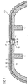
- FIG. 3 each show a molded part 10 for a vehicle interior, comprising a decorative film formed by a plastic film 11 made of polycarbonate (abbreviation: PC), on the back of a carrier 12 is molded.
- the plastic film 11 has on its rear side an opaque printing layer 19 with a plurality of recesses 13 for the passage of light.
- the carrier 12 has a window 14 in the region of the recesses 13 in the pressure layer 19. In the window 14, a functional element 15 comprising a light element 18 and two capacitive sensors 21 is arranged.
- the functional element 15 further comprises capacitive sensors 21, which are designed such that they react to an approach or movement of the finger of an operator.
- the plastic film 11 is on a front side facing away from the back with a transparent or translucent protective and / or optical layer 16 made of polycarbonate (abbreviation: PC) or polymethyl methacrylate (abbreviation: PMMA) or polyurethane (abbreviation: PUR) or polyurea (abbreviation: PUA) overdrawn.
- the protective and / or optical layer 16 has on its surface facing away from the plastic film 11 a recess 20 as a haptic element for guiding the finger of an operator.
- This recess 20 is provided in the region of the recesses 13 in the pressure position, wherein in the example shown, the recess 20 spans all provided recesses 13.
- the recess 20 is provided in the region of the window 14, the recess 20 in the example shown, the window 14 slightly spans, that is substantially the same Dimensions as the window 14 has.
- This recess 20 or an alternative elevation has the additional advantage that it can conceal sink marks that may arise in the production of the protective and / or optical layer 16 in the region of or the window 14 in the carrier 12. Therefore, it is advantageous if the dimensions of the recess 20 or a corresponding elevation at least substantially correspond to the dimensions of the associated window 14.
- the support 12 is opaque, which prevents lateral stray light, and made of polycarbonate (abbreviation: PC) or acrylonitrile-butadiene-styrene (abbreviation: ABS) or a blend of polycarbonate (abbreviation: PC) and acrylonitrile-butadiene-styrene ( abbreviation: ABS).
- PC polycarbonate
- ABS acrylonitrile-butadiene-styrene
- ABS acrylonitrile-butadiene-styrene
- FIG. 1 It is shown that the support 12 may have fastening elements as attachments 17.
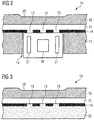
- FIG. 3 shows a section of a further embodiment of the invention.
- the molding 10 according to FIG. 3 comprises a decorative layer formed by a plastic film 11 made of polycarbonate, at the back of a carrier 12 is arranged.
- the plastic film 11 has on one side on its back on an opaque printing layer 19 with a plurality of recesses 13 for the passage of light.
- the carrier 12 is formed as a diffuser 22, which is formed of colored plastic.
- the plastic film 11 is coated on one of its rear side facing away from the front with a transparent protective and / or optical layer 16, which in the example shown on its surface facing away from the plastic film 11 a recess 20 as haptic elements for an operator, in particular for guiding the finger an operator.
- a transparent protective and / or optical layer 16 which in the example shown on its surface facing away from the plastic film 11 a recess 20 as haptic elements for an operator, in particular for guiding the finger an operator.
- a recess 20 as haptic elements for an operator, in particular for guiding the finger an operator.
- an elevation could also be provided here.
Description
- Die Erfindung betrifft ein Formteil, insbesondere ein als Formteil ausgebildetes Dekorteil und/oder Verkleidungsteil für einen Fahrzeuginnenraum, und ein Verfahren zum Herstellen eines solchen Formteils.
- Derartige Formteile umfassen eine von einer Kunststofffolie gebildete Dekorschicht, an deren Rückseite ein Träger angeordnet, insbesondere angespritzt, ist. Die Kunststofffolie weist zumindest einseitig eine lichtundurchlässige Drucklage mit mindestens einer Aussparung zur Lichtdurchführung auf. Der Träger weist mindestens ein Fenster im Bereich der Aussparung in der Drucklage auf, wobei in dem Fenster mindestens ein Funktionselement umfassend mindestens ein Lichtelement und/oder mindestens einen Lichtleiter und mindestens ein Sensorikelement angeordnet ist.
- Solche Formteile für den Fahrzeuginnenraum sind an sich bekannt. Zum Stand der Technik wird verwiesen auf
EP 2 295 293 A1 ,DE 10 2012 110 153 A1 ,DE 20 2010 005 688 U1 ,DE 10 2011 016 417 A1 ,WO 2004 / 024 510 A1 ,DE 10 2009 024 510 A1 ,US 2012 / 280 528 A1 . - Ferner wird zum Stand der Technik verwiesen auf die Druckschriften
DE 197 17 740 A1 ,WO 2005/035299 A1 ,WO 03/033306 A1 US 2002 / 01 01 738 A1 ,DE 10 2008 064 233 A1 . - Jedoch steigen stets die Anforderungen, die an derartige Formteile gestellt werden. Insbesondere werden Lichteffekte zur Verdeutlichung von Symbolen oder Aussparungen gewünscht, um diese auch bei schlechten oder schwachen Lichtverhältnissen erkennbar zu machen oder optisch aufzuwerten. Die präzise Hinterleuchtung von Symbolen oder Aussparungen und/oder kapazitiver Sensorik insbesondere bei großen bzw. großflächigen Formteilen stellte bis dato jedoch ein großes Problem dar.
- Es ist daher Aufgabe der Erfindung, ein neues Formteil, insbesondere ein Formteil mit einer präzisen Hinterleuchtung von Symbolen oder Aussparungen, und ein neues Verfahren, insbesondere zur Herstellung derartiger Formteile, anzugeben.
- Diese Aufgabe wird hinsichtlich des Formteils gelöst durch die Merkmale des Anspruchs 1 und hinsichtlich des Verfahrens durch die Merkmale des Anspruchs 8. Vorteilhafte Ausgestaltungen und Weiterbildungen sind in den jeweils abhängigen Ansprüchen angegeben.
- Das erfindungsgemäße Formteil ist dadurch gekennzeichnet, dass das Sensorikelement mindestens einen kapazitiven Sensor umfasst oder mindestens ein kapazitiver Sensor ist, wobei der kapazitative Sensor derart ausgebildet ist, dass er auf eine Annäherung und/oder Bewegung, insbesondere des Fingers, eines Bedieners reagiert.
- Die Vorteile der Erfindung liegen insbesondere darin, dass durch den Aufbau des Formteils eine präzise Hinterleuchtung von Aussparungen oder von durch diese Aussparungen gebildeten Symbolen möglich ist.
- Die eine oder die mehreren lichtdurchlässigen Ausnehmungen sind hinsichtlich ihrer Form und Anordnung beispielsweise für eine gewünschte Symbolik oder Optik vorgesehen.
- Vorzugsweise ist das Fenster eine Öffnung, die durch den gesamten Träger hindurchgeht. Somit kann das Funktionselement direkt oder zumindest sehr nahe an der Kunststofffolie und damit an der Aussparung in der Drucklage angeordnet werden. Beispielsweise können somit Lichtelement oder Lichtleiter im Fenster derart nahe an der oder den zugeordneten Aussparungen angeordnet sein, dass Streulicht zumindest weitgehend vermieden wird. Auf diese Weise wird eine gezielte Beleuchtung einer oder mehrerer zugeordneter Aussparungen ermöglicht. Weitere Aussparungen, deren Beleuchtung nicht erwünscht ist, werden dann nicht oder zumindest kaum in unerwünschter Weise durch Streulicht beleuchtet und bleiben somit dunkel. Dies ermöglicht eine gezielte Darstellung bestimmter Symbole für einen Betrachter, wobei gleichzeitig andere Symbole für den Betrachter dunkel bleiben und auch nicht durch Streulicht schwach sichtbar werden.
- Vorzugsweise ist der Träger zumindest teilweise lichtundurchlässig ausgebildet, insbesondere zumindest im Bereich um das oder die Fenster. Dies unterstützt die vorstehend bereits im Zusammenhang mit dem Vorsehen von mindestens einem Fenster im Träger angesprochene Vermeidung oder Reduzierung von Streulicht.
- Der Träger kann aus Polycarbonat (Kurzzeichen: PC) oder Acrylnitril-Butadien-Styrol (Kurzzeichen: ABS) oder aus einem Blend aus Polycarbonat (Kurzzeichen: PC) und Acrylnitril-Butadien-Styrol (Kurzzeichen: ABS) gebildet sein.
- Der Träger kann Anbauteile, insbesondere beim Spritzgießen ausgebildete oder eingespritzte Anbauteile, aufweisen. Diese Anbauteile können beispielsweise Befestigungselemente zur Anbringung des Formteils sein, beispielsweise zur Anbringung des Formteils im Innenraum eines Kraftfahrzeugs.
- Gemäß einer bevorzugten Weiterbildung der Erfindung ist vorgesehen, dass der Träger als Diffusor ausgebildet ist. Alternativ oder additiv kann vorgesehen sein, dass zwischen dem Träger und der Kunststofffolie ein Diffusor vorgesehen ist.
- Der Diffusor kann aus lichtdurchlässigem und/oder eingefärbtem Kunststoff, ausgebildet sein. Alternativ oder additiv kann an oder in oder nahe dem Diffusor ein Funktionselement umfassend mindestens ein Lichtelement und/oder mindestens einen Lichtleiter und/oder mindestens ein Sensorikelement angeordnet sein.
- Die Kunststofffolie ist vorzugsweise transparent oder transluzent ausgebildet.
- Eine Weiterbildung der Erfindung sieht vor, dass die Kunststofffolie an ihrer Rückseite die lichtundurchlässige Drucklage mit mindestens einer Aussparung aufweist.
- Vorzugsweise ist die Kunststofffolie aus einem thermoplastischen Kunststoff, insbesondere Polycarbonat (Kurzzeichen: PC) gebildet.
- Besonders bevorzugt ist die Kunststofffolie an einer ihrer Rückseite abgewandten Vorderseite mit einer transparenten oder transluzenten Schutz- und/oder Optikschicht, beispielsweise einer Schutz- und/oder Optikschicht aus Polycarbonat (Kurzzeichen: PC) oder Polymethylmethacrylat (Kurzzeichen: PMMA) oder Polyurethan (Kurzzeichen: PUR) oder Polyurea (Kurzzeichen: PUA), überzogen. Die Schutz- und/oder Optikschicht kann vorzugsweise mittels Sprühlackieren oder Spritzgießen oder RIM-Technik (Reaction Injection Moulding Technik) aufgebracht sein. Ein Vorteil der Schutz- und/oder Optikschicht neben ihren üblichen Schutzeffekten ist der Symbolik-unter-Glas-Effekt, der die Symbole oder hinterleuchteten Aussparungen besonders hochwertig wirken lässt.
- Mit einer transparenten Schutz- und/oder Optikschicht kann das Lichtdesign auch im nicht hinterleuchteten Zustand wahrgenommen werden. Eine transluzente Schutz- und/oder Optikschicht ermöglicht Verschwindeeffekte, so dass ein Betrachter im Tagdesign beispielsweise eine homogene Oberfläche wahrnimmt und im hinterleuchteten Zustand das Lichtdesign hervortritt.
- Vorzugsweise ist die Schutz- und/oder Optikschicht mit einer Hard Coat Lackierung, insbesondere auf Basis von Dual Cure oder Monocure Systemen, überzogen. Dies hat zum Vorteil, dass die Schutz- und/oder Optikschicht hinsichtlich ihrer Beständigkeit weiter veredelt wird.
- Die Schutz- und/oder Optikschicht kann an ihrer der Kunststofffolie abgewandten Oberfläche plan oder glatt oder ohne haptische Elemente ausgebildet sein. Es ist aber auch möglich, dass die Schutz- und/oder Optikschicht an ihrer der Kunststofffolie abgewandten Oberfläche eine oder mehrere Vertiefungen und/oder Erhebungen, vorzugsweise ausgebildet als haptische Elemente für einen Bediener, insbesondere zur Führung des Fingers eines Bedieners, aufweist. Vorzugsweise ist diese oder sind diese Vertiefungen und/oder Erhebungen im Bereich der Aussparung oder der Aussparungen in der Drucklage und/oder im Bereich des Fensters oder der Fenster im Träger in der Schutz- und/oder Optikschicht vorgesehen. Es erweist sich als vorteilhaft, wenn die Abmessungen der jeweiligen Vertiefung und/oder Ergebung den Abmessungen des zugeordneten Fensters entsprechen. Unter "entsprechenden" Abmessungen werden insbesondere Abmessungen verstanden, die maximal 10%, vorzugsweise maximal 5% voneinander abweichen. Eine derartige Vertiefung oder Erhöhung hat den zusätzlichen Vorteil, dass sich dadurch Einfallstellen, die bei der Herstellung der Schutz- und/oder Optikschicht im Bereich des zugeordneten Fensters im Träger entstehen können, kaschieren lassen.
- Bei dem erfindungsgemäßen Verfahren zum Herstellen des erfindungsgemäßen Formteils wird eine zumindest einseitig lichtundurchlässig mit einer Drucklage bedruckte Folie an ihrer Rückseite mittels Spritzgießen mit einem Träger hinterspritzt.
- Erfindungsgemäß wird beim Anspritzen des Trägers mindestens ein Fenster ausgespart. Anschließend wird im Bereich des Fensters die mindestens eine Aussparung zur Lichtdurchführung in die Drucklage eingebracht, wobei in das Fenster mindestens ein Funktionselement mit mindestens einem Lichtelement oder mindestens einem Lichtleiter und/oder mindestens ein Sensorikelement eingebracht wird.
- Es kann vorgesehen sein, dass als Träger oder zwischen Träger und Kunststofffolie ein Diffusor, insbesondere ein Diffusor aus lichtdurchlässigem und/oder eingefärbtem Kunststoff, vorgesehen, insbesondere angespritzt, wird, wobei vor dem Hinterspritzen der Kunststofffolie die mindestens eine Aussparung zur Lichtdurchführung in die Drucklage eingebracht wird.
- Ferner kann vorgesehen sein, dass die Kunststofffolie vor dem Hinterspritzen an einer als Rückseite im Formteil vorgesehenen Seite, insbesondere mittels eines Siebdruckverfahrens, bedruckt wird oder bedruckt ist.
- Eine Weiterbildung der Erfindung sieht vor, dass die mindestens eine Aussparung zur Lichtdurchführung mittels Laserabtrag in die Drucklage eingebracht wird, wobei insbesondere vorgesehen ist, vor dem Einbringen der mindestens einen Ausnehmung die Kunststofffolie in eine vorgesehene Form zu bringen.
- Eine Weiterbildung des erfindungsgemäßen Verfahrens sieht vor, dass Symbole mit lichtundurchlässiger Farbe im Bereich der mindestens einen Aussparung zur Lichtdurchführung auf die Kunststofffolie, beispielsweise im Tampondruckverfahren oder Digitaldruckverfahren, aufgedruckt werden. Beispielsweise können die Symbole durch die Farbe, vorzugsweise im Tampondruckverfahren oder Digitaldruckverfahren, farblich gestaltet werden.
- Bevorzugt wird eine transparente oder transluzente Schutz- und/oder Optikschicht auf einer als Vorderseite im Formteil vorgesehenen Seite der Kunststofffolie aufgebracht, insbesondere mittels Sprühlackieren oder Spritzgießen oder RIM-Technik, vorzugsweise eine Schutz- und/oder Optikschicht aus Polycarbonat (Kurzzeichen: PC) oder Polymethylmethacrylat (Kurzzeichen: PMMA) oder Polyurethan (Kurzzeichen: PUR) oder Polyurea (Kurzzeichen: PUA). Bevorzugt wird die Schutz- und/oder Optikschicht aufgebracht bevor die lichtdurchlässigen Ausnehmungen mittels Laserabtrag in die Drucklage eingebracht wurden.
- Gemäß einer Ausführungsvariante der Erfindung werden beim Hinterspritzen Anbauteile an der Rückseite des Trägers ausgebildet oder eingespritzt.
- Die Erfindung wird nachstehend auch hinsichtlich weiterer Merkmale und Vorteile anhand der Beschreibung von Ausführungsbeispielen und unter Bezugnahme auf die beiliegenden, schematischen Zeichnungen näher erläutert. Dabei zeigen
- FIG 1
- in einer schematischen Querschnittsdarstellung ein Ausführungsbeispiel eines erfindungsgemäßen Formteils, und
- FIG 2
- in einer schematischen Querschnittsdarstellung einen Ausschnitt eines Ausführungsbeispiels eines erfindungsgemäßen Formteils, sowie
- FIG 3
- in einer schematischen Querschnittsdarstellung einen Ausschnitt eines weiteren Ausführungsbeispiels eines erfindungsgemäßen Formteils.
- Einander entsprechende Teile und Komponenten sind jeweils mit den gleichen Bezugszeichen bezeichnet.
-
FIG 1 bis FIG 3 zeigen jeweils ein Formteil 10 für einen Fahrzeuginnenraum, umfassend eine von einer Kunststofffolie 11 aus Polycarbonat (Kurzzeichen: PC) gebildete Dekorschicht, an deren Rückseite ein Träger 12 angespritzt ist. Die Kunststofffolie 11 weist an ihrer Rückseite eine lichtundurchlässig Drucklage 19 mit mehreren Aussparungen 13 zur Lichtdurchführung auf. Der Träger 12 weist ein Fenster 14 im Bereich der Aussparungen 13 in der Drucklage 19 auf. In dem Fenster 14 ist ein Funktionselement 15 umfassend ein Lichtelement 18 und zwei kapazitive Sensoren 21 angeordnet. - Das Funktionselement 15 umfasst ferner kapazitive Sensoren 21, die derart ausgebildet sind, dass sie auf eine Annäherung bzw. Bewegung des Fingers eines Bedieners reagieren.
- Die Kunststofffolie 11 ist an einer ihrer Rückseite abgewandten Vorderseite mit einer transparenten oder transluzenten Schutz- und/oder Optikschicht 16 aus Polycarbonat (Kurzzeichen: PC) oder Polymethylmethacrylat (Kurzzeichen: PMMA) oder Polyurethan (Kurzzeichen: PUR) oder Polyurea (Kurzzeichen: PUA) überzogen. Die Schutz- und/oder Optikschicht 16 weist an ihrer der Kunststofffolie 11 abgewandten Oberfläche eine Vertiefung 20 als haptisches Element zur Führung des Fingers eines Bedieners auf. Diese Vertiefung 20 ist im Bereich der Aussparungen 13 in der Drucklage vorgesehen, wobei im dargestellten Beispiel die Vertiefung 20 alle vorgesehenen Aussparungen 13 überspannt. Da das Fenster 14 im Träger 12 im Bereich der Aussparungen 13 in der Drucklage 19 vorgesehen ist, ist auch die Vertiefung 20 im Bereich des Fensters 14 vorgesehen, wobei die Vertiefung 20 im dargestellten Beispiel das Fenster 14 geringfügig überspannt, das heißt im Wesentlichen die gleichen Abmessungen wie das Fenster 14 aufweist. Alternativ zur dargestellten Vertiefung 20 könnte auch einer Erhebung vorgesehen sein. Diese Vertiefung 20 bzw. eine alternative Erhöhung hat den zusätzlichen Vorteil, dass sich dadurch Einfallstellen, die bei der Herstellung der Schutz- und/oder Optikschicht 16 im Bereich des oder der Fenster 14 im Träger 12 entstehen können, kaschieren lassen. Daher ist es vorteilhaft, wenn die Abmessungen der Vertiefung 20 bzw. einer entsprechenden Erhebung zumindest im Wesentlichen den Abmessungen des zugeordneten Fensters 14 entsprechen.
- Der Träger 12 ist lichtundurchlässig ausgebildet, wodurch seitliches Streulicht verhindert wird, und aus Polycarbonat (Kurzzeichen: PC) oder Acrylnitril-Butadien-Styrol (Kurzzeichen: ABS) oder aus einem Blend aus Polycarbonat (Kurzzeichen: PC) und Acrylnitril-Butadien-Styrol (Kurzzeichen: ABS) gebildet. In
FIG 1 ist gezeigt, dass der Träger 12 Befestigungselemente als Anbauteile 17 aufweisen kann. -
FIG 3 zeigt einen Ausschnitt einer weiteren Ausführungsvariante der Erfindung. Das Formteil 10 gemäßFIG 3 umfasst eine von einer Kunststofffolie 11 aus Polycarbonat gebildete Dekorschicht, an deren Rückseite ein Träger 12 angeordnet ist. Die Kunststofffolie 11 weist einseitig an ihrer Rückseite eine lichtundurchlässige Drucklage 19 mit mehreren Aussparungen 13 zur Lichtdurchführung auf. Der Träger 12 ist als Diffusor 22 ausgebildet, der aus eingefärbtem Kunststoff gebildet ist. - Die Kunststofffolie 11 ist an einer ihrer der Rückseite abgewandten Vorderseite mit einer transparenten Schutz- und/oder Optikschicht 16 überzogen, wobei diese im dargestellten Beispiel an ihrer der Kunststofffolie 11 abgewandten Oberfläche eine Vertiefung 20 als haptische Elemente für einen Bediener, insbesondere zur Führung des Fingers eines Bedieners, aufweist. Alternativ zur Vertiefung 20 könnte auch hier eine Erhebung vorgesehen sein. Es ist aber auch möglich, weder eine Vertiefung noch eine Erhebung vorzusehen, das heißt die Oberfläche der Schutz- und/oder Optikschicht 16 könnte beispielsweise auch völlig plan oder glatt ausgebildet sein, insbesondere ohne haptische Elemente für einen Bediener.
-
- 10
- Formteil
- 11
- Kunststofffolie
- 12
- Träger
- 13
- Aussparung
- 14
- Fenster
- 15
- Funktionselement
- 16
- Schutz- und/oder Optikschicht
- 17
- Anbauteil
- 18
- Lichtelement
- 19
- Drucklage
- 20
- Vertiefung
- 21
- Kapazitiver Sensor
- 22
- Diffusor
Claims (12)
- Formteil (10),
umfassend eine von einer Kunststofffolie (11) gebildete Dekorschicht, an deren Rückseite ein Träger (12) angeordnet ist,
wobei die Kunststofffolie (11) zumindest einseitig eine lichtundurchlässige Drucklage (19) mit mindestens einer Aussparung (13) zur Lichtdurchführung aufweist,
wobei der Träger (12) mindestens ein Fenster (14) im Bereich der Aussparung (13) in der Drucklage aufweist,
wobei in dem Fenster (14) mindestens ein Funktionselement (15) umfassend mindestens ein Lichtelement (18) und/oder mindestens einen Lichtleiter und mindestens ein Sensorikelement angeordnet ist,
dadurch gekennzeichnet, dass
das Sensorikelement mindestens einen kapazitiven Sensor (21) umfasst oder mindestens ein kapazitiver Sensor (21) ist, wobei der kapazitative Sensor (21) derart ausgebildet ist, dass er auf eine Annäherung und/oder Bewegung eines Bedieners reagiert. - Formteil nach Anspruch 1,
dadurch gekennzeichnet, dass
der Träger (12) lichtundurchlässig ausgebildet ist, und/oder aus Polycarbonat (Kurzzeichen: PC) oder Acrylnitril-Butadien-Styrol (Kurzzeichen: ABS) oder aus einem Blend aus Polycarbonat (Kurzzeichen: PC) und Acrylnitril-Butadien-Styrol (Kurzzeichen: ABS) gebildet ist, und/oder Anbauteile (17) aufweist. - Formteil nach einem der vorhergehenden Ansprüche,
dadurch gekennzeichnet,
dass der Träger (12) als Diffusor (22) ausgebildet ist, und/oder dass zwischen dem Träger (12) und der Kunststofffolie (11) ein Diffusor (22) vorgesehen ist. - Formteil nach Anspruch 3,
dadurch gekennzeichnet,
dass der Diffusor (22) aus lichtdurchlässigem und/oder eingefärbtem Kunststoff, ausgebildet ist, und/oder
dass an oder in oder nahe dem Diffusor (22) ein Funktionselement (15) umfassend mindestens ein Lichtelement (18) und/oder mindestens einen Lichtleiter und/oder mindestens ein Sensorikelement angeordnet ist. - Formteil nach einem der vorhergehenden Ansprüche,
dadurch gekennzeichnet,
dass die Kunststofffolie (11) transparent oder transluzent ausgebildet ist, wobei die Kunststofffolie (11) an ihrer Rückseite die lichtundurchlässige Drucklage (19) mit mindestens einer Aussparung (13) aufweist, und/oder
dass die Kunststofffolie (11) aus einem thermoplastischen Kunststoff gebildet ist. - Formteil nach einem der vorhergehenden Ansprüche,
dadurch gekennzeichnet, dass
die Kunststofffolie (11) an einer ihrer der Rückseite abgewandten Vorderseite mit einer transparenten oder transluzenten Schutz- und/oder Optikschicht (16) überzogen ist. - Formteil nach Anspruch 6,
dadurch gekennzeichnet, dass
die Schutz- und/oder Optikschicht (16) an ihrer der Kunststofffolie (11) abgewandten Oberfläche eine oder mehrere Vertiefungen (20) und/oder Erhebungen als haptische Elemente für einen Bediener aufweist. - Verfahren zum Herstellen eines Formteils (10) nach einem der vorhergehenden Ansprüche,
bei dem eine zumindest einseitig lichtundurchlässig mit einer Drucklage (19) bedruckte Kunststofffolie (11) an ihrer Rückseite mittels Spritzgießen mit einem Träger (12) hinterspritzt wird,
dadurch gekennzeichnet, dass
beim Anspritzen des Trägers mindestens ein Fenster (14) ausgespart wird,
wobei anschließend im Bereich des Fensters (14) die mindestens eine Aussparung (13) zur Lichtdurchführung in die Drucklage (19) eingebracht wird,
wobei in das Fenster (14) mindestens ein Funktionselement (15) mit mindestens einem Lichtelement (18) oder mindestens einem Lichtleiter und/oder mindestens ein Sensorikelement eingebracht wird. - Verfahren nach Anspruch 8,
dadurch gekennzeichnet, dass
als Träger (12) oder zwischen Träger (12) und Kunststofffolie (11) ein Diffusor (22) vorgesehen wird,
wobei vor dem Hinterspritzen der Kunststofffolie (11) die mindestens eine Aussparung (13) zur Lichtdurchführung in die Drucklage (19) eingebracht wird. - Verfahren nach einem der Ansprüche 8 oder 9,
dadurch gekennzeichnet,
dass die Kunststofffolie (11) vor dem Hinterspritzen an einer als Rückseite im Formteil vorgesehenen Seite bedruckt wird oder bedruckt ist, und/oder
dass die mindestens eine Aussparung (13) zur Lichtdurchführung mittels Laserabtrag in die Drucklage (19) eingebracht wird. - Verfahren nach einem der Ansprüche 8 bis 10,
dadurch gekennzeichnet, dass
Symbole mit lichtundurchlässiger Farbe im Bereich der mindestens einen Aussparung (13) zur Lichtdurchführung auf die Kunststofffolie (11) aufgedruckt werden. - Verfahren nach einem der Ansprüche 8 bis 11,
dadurch gekennzeichnet, dass
eine transparente oder transluzente Schutz- und/oder Optikschicht (16) auf einer als Vorderseite im Formteil (10) vorgesehenen Seite der Kunststofffolie (11) aufgebracht wird.
Applications Claiming Priority (1)
| Application Number | Priority Date | Filing Date | Title |
|---|---|---|---|
| DE102015101013.5A DE102015101013A1 (de) | 2015-01-23 | 2015-01-23 | Formteil, insbesondere als Formteil ausgebildetes Dekorteil und/oder Verkleidungsteil für einen Fahrzeuginnenraum, und Verfahren zum Herstellen eines Formteils |
Publications (2)
| Publication Number | Publication Date |
|---|---|
| EP3048015A1 EP3048015A1 (de) | 2016-07-27 |
| EP3048015B1 true EP3048015B1 (de) | 2019-06-19 |
Family
ID=55182276
Family Applications (1)
| Application Number | Title | Priority Date | Filing Date |
|---|---|---|---|
| EP16152168.7A Active EP3048015B1 (de) | 2015-01-23 | 2016-01-21 | Formteil, insbesondere als formteil ausgebildetes dekorteil und/oder verkleidungsteil für einen fahrzeuginnenraum, und verfahren zum herstellen eines formteils |
Country Status (2)
| Country | Link |
|---|---|
| EP (1) | EP3048015B1 (de) |
| DE (1) | DE102015101013A1 (de) |
Cited By (2)
| Publication number | Priority date | Publication date | Assignee | Title |
|---|---|---|---|---|
| WO2023213607A1 (en) * | 2022-05-04 | 2023-11-09 | Agc Glass Europe | Decorative glass panel for vehicle's interior |
| DE102022116953A1 (de) | 2022-07-07 | 2024-01-18 | Novem Car Interior Design Gmbh | Formteil |
Families Citing this family (6)
| Publication number | Priority date | Publication date | Assignee | Title |
|---|---|---|---|---|
| DE102017203888A1 (de) | 2017-03-09 | 2018-09-13 | Bayerische Motoren Werke Aktiengesellschaft | Fahrzeugbauteil mit einer Funktionsschicht |
| DE102017119292B3 (de) * | 2017-08-23 | 2019-01-24 | Novem Car Interior Design Gmbh | Formteil, insbesondere als Formteil ausgebildetes Dekorteil und/oder Verkleidungsteil für einen Fahrzeuginnenraum und ein Verfahren zum Herstellen eines solchen Formteils |
| CN114126922B (zh) | 2018-11-23 | 2024-01-05 | 上海延锋金桥汽车饰件系统有限公司 | 车辆内部部件 |
| DE102018131978A1 (de) * | 2018-12-12 | 2020-06-18 | Bayerische Motoren Werke Aktiengesellschaft | Innenverkleidungsteil und Verfahren zu dessen Herstellung |
| EP3552792A1 (de) | 2019-07-19 | 2019-10-16 | WEIDPLAS GmbH | Bauteil mit trägerteil und deckschicht sowie verfahren zur herstellung eines solchen bauteils |
| EP4253156A1 (de) * | 2022-03-29 | 2023-10-04 | Motherson Innovations Company Limited | Innenverkleidungsteil eines fahrzeugs, fahrzeug mit einem solchen innenverkleidungsteil und verfahren zur herstellung eines solchen innenverkleidungsteils |
Citations (3)
| Publication number | Priority date | Publication date | Assignee | Title |
|---|---|---|---|---|
| DE19717740A1 (de) * | 1997-04-26 | 1998-11-05 | Schoenberg & Cerny Gmbh | Kunststoff-Formkörper mit integriertem optoelektronischem Leuchtelement |
| WO2003033306A1 (de) * | 2001-10-16 | 2003-04-24 | Burg Design Gmbh | Dekorelement und mit einem dekorelement versehenes kunststoffteil |
| WO2005035299A1 (de) * | 2003-09-18 | 2005-04-21 | Daimlerchrysler Ag | Bedien- und anzeigeeinheit |
Family Cites Families (7)
| Publication number | Priority date | Publication date | Assignee | Title |
|---|---|---|---|---|
| DE10240270A1 (de) * | 2002-08-31 | 2004-03-18 | Johnson Controls Gmbh | Verkleidungselement für den Innenraum eines Fahrzeugs |
| DE102009024989A1 (de) * | 2009-06-16 | 2010-12-30 | Lisa Dräxlmaier GmbH | Dekorschicht mit beidseitigen Ausnehmungen |
| ATE552144T1 (de) * | 2009-09-11 | 2012-04-15 | Weidmann Plastics Tech Ag | Verfahren zum herstellen eines bauteils mit einem flächigen dekorelement und bauteil mit einem flächigen dekorelement |
| DE202010005688U1 (de) * | 2010-06-21 | 2011-09-02 | Novem Car Interior Design Gmbh | Formteil mit Lichtleitern zur Symboldarstellung |
| DE102011016417A1 (de) * | 2011-04-08 | 2012-10-11 | GM Global Technology Operations LLC (n. d. Gesetzen des Staates Delaware) | Leuchtendes Formteil, insbesondere Dekorteil und/oder Verkleidungsteil für einen Fahrzeuginnenraum |
| US20120280528A1 (en) * | 2011-05-06 | 2012-11-08 | Ford Global Technologies, Llc | Vehicle accent molding with puddle light |
| DE102012110153A1 (de) * | 2012-02-17 | 2013-08-22 | Novem Car Interior Design Gmbh | Formteil und Verfahren zur Herstellung dieses Formteils |
-
2015
- 2015-01-23 DE DE102015101013.5A patent/DE102015101013A1/de not_active Withdrawn
-
2016
- 2016-01-21 EP EP16152168.7A patent/EP3048015B1/de active Active
Patent Citations (3)
| Publication number | Priority date | Publication date | Assignee | Title |
|---|---|---|---|---|
| DE19717740A1 (de) * | 1997-04-26 | 1998-11-05 | Schoenberg & Cerny Gmbh | Kunststoff-Formkörper mit integriertem optoelektronischem Leuchtelement |
| WO2003033306A1 (de) * | 2001-10-16 | 2003-04-24 | Burg Design Gmbh | Dekorelement und mit einem dekorelement versehenes kunststoffteil |
| WO2005035299A1 (de) * | 2003-09-18 | 2005-04-21 | Daimlerchrysler Ag | Bedien- und anzeigeeinheit |
Cited By (2)
| Publication number | Priority date | Publication date | Assignee | Title |
|---|---|---|---|---|
| WO2023213607A1 (en) * | 2022-05-04 | 2023-11-09 | Agc Glass Europe | Decorative glass panel for vehicle's interior |
| DE102022116953A1 (de) | 2022-07-07 | 2024-01-18 | Novem Car Interior Design Gmbh | Formteil |
Also Published As
| Publication number | Publication date |
|---|---|
| EP3048015A1 (de) | 2016-07-27 |
| DE102015101013A1 (de) | 2016-07-28 |
Similar Documents
| Publication | Publication Date | Title |
|---|---|---|
| EP3048015B1 (de) | Formteil, insbesondere als formteil ausgebildetes dekorteil und/oder verkleidungsteil für einen fahrzeuginnenraum, und verfahren zum herstellen eines formteils | |
| DE202016100258U1 (de) | Formteil, insbesondere als Formteil ausgebildetes Dekorteil und/oder Verkleidungsteil für einen Fahrzeuginnenraum | |
| EP2529912B1 (de) | Funktionsträger mit Tastenfunktionen | |
| DE102015101012B4 (de) | Formteil, insbesondere als Formteil ausgebildetes Dekorteil und/oder Verkleidungsteil für einen Fahrzeuginnenraum, und Verfahren zum Herstellen eines derartigen Formteils | |
| DE202017104082U1 (de) | Formteil, insbesondere als Formteil ausgebildetes Dekorteil und/oder Verkleidungsteil für einen Fahrzeuginnenraum | |
| DE102010017494B4 (de) | Formteil mit Lichtleitern zur Symboldarstellung und Verfahren zu seiner Herstellung | |
| DE102012023135B4 (de) | Dekorteil | |
| EP3088156B1 (de) | Verfahren zum herstellen eines beleuchtbaren anbauteils, beleuchtbares anbauteil und kraftfahrzeug mit einem anbauteil | |
| EP2942233B1 (de) | Flächiges beleuchtungselement für die innenausstattung eines fahrzeugs | |
| DE102011103200A1 (de) | Lichtfenster | |
| EP3233491B1 (de) | Verfahren zur herstellung eines kunststoff-fahrzeuganbauteils | |
| EP2803463A1 (de) | Funktionsträger mit Tastenfunktionen | |
| DE102012211951A1 (de) | Zierteil für Kraftfahrzeuge und Verfahren zu seiner Herstellung | |
| DE102012105412A1 (de) | Beleuchtbares Verkleidungsbauteil für ein Fahrzeug und Verfahren zu dessen Herstellung | |
| DE102015120120A1 (de) | Formteil, insbesondere als Formteil ausgebildetes Dekorteil und/oder Verkleidungsteil für einen Fahrzeuginnenraum, und Verfahren zum Herstellen eines derartigen Formteils | |
| DE102005023440A1 (de) | Anzeige- und/oder Bedienungspaneel | |
| DE102012110153A1 (de) | Formteil und Verfahren zur Herstellung dieses Formteils | |
| DE10332975B4 (de) | Dekor-Zierteil | |
| DE202015106328U1 (de) | Formteil, insbesondere als Formteil ausgebildetes Dekorteil und/oder Verkleidungsteil für einen Fahrzeuginnenraum | |
| DE102017115304A1 (de) | Formteil, insbesondere als Formteil ausgebildetes Dekorteil und/oder Verkleidungsteil für einen Fahrzeuginnenraum, und Verfahren zum Herstellen eines derartigen Formteils | |
| DE202015100321U1 (de) | Formteil, insbesondere als Formteil ausgebildetes Dekorteil und/oder Verkleidungsteil für einen Fahrzeuginnenraum | |
| DE102008064233A1 (de) | Einstiegsleiste für Kraftfahrzeuge | |
| EP3554883B1 (de) | Formteil und verfahren zum herstellen eines formteils | |
| DE202015103830U1 (de) | Formteil, insbesondere ein als Formteil ausgebildetes Dekorteil und/oder Verkleidungsteil für einen Fahrzeuginnenraum | |
| DE102012003412A1 (de) | Hinterleuchtetes Formteil und dessen Herstellungsverfahren |
Legal Events
| Date | Code | Title | Description |
|---|---|---|---|
| PUAI | Public reference made under article 153(3) epc to a published international application that has entered the european phase |
Free format text: ORIGINAL CODE: 0009012 |
|
| AK | Designated contracting states |
Kind code of ref document: A1 Designated state(s): AL AT BE BG CH CY CZ DE DK EE ES FI FR GB GR HR HU IE IS IT LI LT LU LV MC MK MT NL NO PL PT RO RS SE SI SK SM TR |
|
| AX | Request for extension of the european patent |
Extension state: BA ME |
|
| STAA | Information on the status of an ep patent application or granted ep patent |
Free format text: STATUS: REQUEST FOR EXAMINATION WAS MADE |
|
| 17P | Request for examination filed |
Effective date: 20170127 |
|
| RBV | Designated contracting states (corrected) |
Designated state(s): AL AT BE BG CH CY CZ DE DK EE ES FI FR GB GR HR HU IE IS IT LI LT LU LV MC MK MT NL NO PL PT RO RS SE SI SK SM TR |
|
| TPAC | Observations filed by third parties |
Free format text: ORIGINAL CODE: EPIDOSNTIPA |
|
| STAA | Information on the status of an ep patent application or granted ep patent |
Free format text: STATUS: EXAMINATION IS IN PROGRESS |
|
| TPAC | Observations filed by third parties |
Free format text: ORIGINAL CODE: EPIDOSNTIPA |
|
| 17Q | First examination report despatched |
Effective date: 20170816 |
|
| TPAC | Observations filed by third parties |
Free format text: ORIGINAL CODE: EPIDOSNTIPA |
|
| TPAC | Observations filed by third parties |
Free format text: ORIGINAL CODE: EPIDOSNTIPA |
|
| TPAC | Observations filed by third parties |
Free format text: ORIGINAL CODE: EPIDOSNTIPA |
|
| GRAP | Despatch of communication of intention to grant a patent |
Free format text: ORIGINAL CODE: EPIDOSNIGR1 |
|
| STAA | Information on the status of an ep patent application or granted ep patent |
Free format text: STATUS: GRANT OF PATENT IS INTENDED |
|
| INTG | Intention to grant announced |
Effective date: 20190205 |
|
| GRAS | Grant fee paid |
Free format text: ORIGINAL CODE: EPIDOSNIGR3 |
|
| GRAA | (expected) grant |
Free format text: ORIGINAL CODE: 0009210 |
|
| STAA | Information on the status of an ep patent application or granted ep patent |
Free format text: STATUS: THE PATENT HAS BEEN GRANTED |
|
| AK | Designated contracting states |
Kind code of ref document: B1 Designated state(s): AL AT BE BG CH CY CZ DE DK EE ES FI FR GB GR HR HU IE IS IT LI LT LU LV MC MK MT NL NO PL PT RO RS SE SI SK SM TR |
|
| REG | Reference to a national code |
Ref country code: GB Ref legal event code: FG4D Free format text: NOT ENGLISH |
|
| REG | Reference to a national code |
Ref country code: CH Ref legal event code: EP |
|
| REG | Reference to a national code |
Ref country code: IE Ref legal event code: FG4D Free format text: LANGUAGE OF EP DOCUMENT: GERMAN |
|
| REG | Reference to a national code |
Ref country code: DE Ref legal event code: R096 Ref document number: 502016005100 Country of ref document: DE |
|
| REG | Reference to a national code |
Ref country code: AT Ref legal event code: REF Ref document number: 1145068 Country of ref document: AT Kind code of ref document: T Effective date: 20190715 |
|
| REG | Reference to a national code |
Ref country code: SE Ref legal event code: TRGR |
|
| REG | Reference to a national code |
Ref country code: NL Ref legal event code: MP Effective date: 20190619 |
|
| PG25 | Lapsed in a contracting state [announced via postgrant information from national office to epo] |
Ref country code: AL Free format text: LAPSE BECAUSE OF FAILURE TO SUBMIT A TRANSLATION OF THE DESCRIPTION OR TO PAY THE FEE WITHIN THE PRESCRIBED TIME-LIMIT Effective date: 20190619 Ref country code: FI Free format text: LAPSE BECAUSE OF FAILURE TO SUBMIT A TRANSLATION OF THE DESCRIPTION OR TO PAY THE FEE WITHIN THE PRESCRIBED TIME-LIMIT Effective date: 20190619 Ref country code: HR Free format text: LAPSE BECAUSE OF FAILURE TO SUBMIT A TRANSLATION OF THE DESCRIPTION OR TO PAY THE FEE WITHIN THE PRESCRIBED TIME-LIMIT Effective date: 20190619 Ref country code: LT Free format text: LAPSE BECAUSE OF FAILURE TO SUBMIT A TRANSLATION OF THE DESCRIPTION OR TO PAY THE FEE WITHIN THE PRESCRIBED TIME-LIMIT Effective date: 20190619 Ref country code: NO Free format text: LAPSE BECAUSE OF FAILURE TO SUBMIT A TRANSLATION OF THE DESCRIPTION OR TO PAY THE FEE WITHIN THE PRESCRIBED TIME-LIMIT Effective date: 20190919 |
|
| REG | Reference to a national code |
Ref country code: LT Ref legal event code: MG4D |
|
| PG25 | Lapsed in a contracting state [announced via postgrant information from national office to epo] |
Ref country code: LV Free format text: LAPSE BECAUSE OF FAILURE TO SUBMIT A TRANSLATION OF THE DESCRIPTION OR TO PAY THE FEE WITHIN THE PRESCRIBED TIME-LIMIT Effective date: 20190619 Ref country code: GR Free format text: LAPSE BECAUSE OF FAILURE TO SUBMIT A TRANSLATION OF THE DESCRIPTION OR TO PAY THE FEE WITHIN THE PRESCRIBED TIME-LIMIT Effective date: 20190920 Ref country code: BG Free format text: LAPSE BECAUSE OF FAILURE TO SUBMIT A TRANSLATION OF THE DESCRIPTION OR TO PAY THE FEE WITHIN THE PRESCRIBED TIME-LIMIT Effective date: 20190919 Ref country code: RS Free format text: LAPSE BECAUSE OF FAILURE TO SUBMIT A TRANSLATION OF THE DESCRIPTION OR TO PAY THE FEE WITHIN THE PRESCRIBED TIME-LIMIT Effective date: 20190619 |
|
| PG25 | Lapsed in a contracting state [announced via postgrant information from national office to epo] |
Ref country code: RO Free format text: LAPSE BECAUSE OF FAILURE TO SUBMIT A TRANSLATION OF THE DESCRIPTION OR TO PAY THE FEE WITHIN THE PRESCRIBED TIME-LIMIT Effective date: 20190619 Ref country code: NL Free format text: LAPSE BECAUSE OF FAILURE TO SUBMIT A TRANSLATION OF THE DESCRIPTION OR TO PAY THE FEE WITHIN THE PRESCRIBED TIME-LIMIT Effective date: 20190619 Ref country code: CZ Free format text: LAPSE BECAUSE OF FAILURE TO SUBMIT A TRANSLATION OF THE DESCRIPTION OR TO PAY THE FEE WITHIN THE PRESCRIBED TIME-LIMIT Effective date: 20190619 Ref country code: PT Free format text: LAPSE BECAUSE OF FAILURE TO SUBMIT A TRANSLATION OF THE DESCRIPTION OR TO PAY THE FEE WITHIN THE PRESCRIBED TIME-LIMIT Effective date: 20191021 Ref country code: EE Free format text: LAPSE BECAUSE OF FAILURE TO SUBMIT A TRANSLATION OF THE DESCRIPTION OR TO PAY THE FEE WITHIN THE PRESCRIBED TIME-LIMIT Effective date: 20190619 Ref country code: SK Free format text: LAPSE BECAUSE OF FAILURE TO SUBMIT A TRANSLATION OF THE DESCRIPTION OR TO PAY THE FEE WITHIN THE PRESCRIBED TIME-LIMIT Effective date: 20190619 |
|
| PG25 | Lapsed in a contracting state [announced via postgrant information from national office to epo] |
Ref country code: IT Free format text: LAPSE BECAUSE OF FAILURE TO SUBMIT A TRANSLATION OF THE DESCRIPTION OR TO PAY THE FEE WITHIN THE PRESCRIBED TIME-LIMIT Effective date: 20190619 Ref country code: IS Free format text: LAPSE BECAUSE OF FAILURE TO SUBMIT A TRANSLATION OF THE DESCRIPTION OR TO PAY THE FEE WITHIN THE PRESCRIBED TIME-LIMIT Effective date: 20191019 Ref country code: SM Free format text: LAPSE BECAUSE OF FAILURE TO SUBMIT A TRANSLATION OF THE DESCRIPTION OR TO PAY THE FEE WITHIN THE PRESCRIBED TIME-LIMIT Effective date: 20190619 Ref country code: ES Free format text: LAPSE BECAUSE OF FAILURE TO SUBMIT A TRANSLATION OF THE DESCRIPTION OR TO PAY THE FEE WITHIN THE PRESCRIBED TIME-LIMIT Effective date: 20190619 |
|
| PG25 | Lapsed in a contracting state [announced via postgrant information from national office to epo] |
Ref country code: TR Free format text: LAPSE BECAUSE OF FAILURE TO SUBMIT A TRANSLATION OF THE DESCRIPTION OR TO PAY THE FEE WITHIN THE PRESCRIBED TIME-LIMIT Effective date: 20190619 |
|
| PG25 | Lapsed in a contracting state [announced via postgrant information from national office to epo] |
Ref country code: DK Free format text: LAPSE BECAUSE OF FAILURE TO SUBMIT A TRANSLATION OF THE DESCRIPTION OR TO PAY THE FEE WITHIN THE PRESCRIBED TIME-LIMIT Effective date: 20190619 Ref country code: PL Free format text: LAPSE BECAUSE OF FAILURE TO SUBMIT A TRANSLATION OF THE DESCRIPTION OR TO PAY THE FEE WITHIN THE PRESCRIBED TIME-LIMIT Effective date: 20190619 |
|
| PG25 | Lapsed in a contracting state [announced via postgrant information from national office to epo] |
Ref country code: IS Free format text: LAPSE BECAUSE OF FAILURE TO SUBMIT A TRANSLATION OF THE DESCRIPTION OR TO PAY THE FEE WITHIN THE PRESCRIBED TIME-LIMIT Effective date: 20200224 |
|
| REG | Reference to a national code |
Ref country code: DE Ref legal event code: R097 Ref document number: 502016005100 Country of ref document: DE |
|
| PLBE | No opposition filed within time limit |
Free format text: ORIGINAL CODE: 0009261 |
|
| STAA | Information on the status of an ep patent application or granted ep patent |
Free format text: STATUS: NO OPPOSITION FILED WITHIN TIME LIMIT |
|
| PG2D | Information on lapse in contracting state deleted |
Ref country code: IS |
|
| 26N | No opposition filed |
Effective date: 20200603 |
|
| PG25 | Lapsed in a contracting state [announced via postgrant information from national office to epo] |
Ref country code: SI Free format text: LAPSE BECAUSE OF FAILURE TO SUBMIT A TRANSLATION OF THE DESCRIPTION OR TO PAY THE FEE WITHIN THE PRESCRIBED TIME-LIMIT Effective date: 20190619 Ref country code: MC Free format text: LAPSE BECAUSE OF FAILURE TO SUBMIT A TRANSLATION OF THE DESCRIPTION OR TO PAY THE FEE WITHIN THE PRESCRIBED TIME-LIMIT Effective date: 20190619 |
|
| REG | Reference to a national code |
Ref country code: CH Ref legal event code: PL |
|
| GBPC | Gb: european patent ceased through non-payment of renewal fee |
Effective date: 20200121 |
|
| REG | Reference to a national code |
Ref country code: BE Ref legal event code: MM Effective date: 20200131 |
|
| PG25 | Lapsed in a contracting state [announced via postgrant information from national office to epo] |
Ref country code: LU Free format text: LAPSE BECAUSE OF NON-PAYMENT OF DUE FEES Effective date: 20200121 Ref country code: GB Free format text: LAPSE BECAUSE OF NON-PAYMENT OF DUE FEES Effective date: 20200121 |
|
| PG25 | Lapsed in a contracting state [announced via postgrant information from national office to epo] |
Ref country code: CH Free format text: LAPSE BECAUSE OF NON-PAYMENT OF DUE FEES Effective date: 20200131 Ref country code: LI Free format text: LAPSE BECAUSE OF NON-PAYMENT OF DUE FEES Effective date: 20200131 Ref country code: BE Free format text: LAPSE BECAUSE OF NON-PAYMENT OF DUE FEES Effective date: 20200131 |
|
| PG25 | Lapsed in a contracting state [announced via postgrant information from national office to epo] |
Ref country code: IE Free format text: LAPSE BECAUSE OF NON-PAYMENT OF DUE FEES Effective date: 20200121 |
|
| REG | Reference to a national code |
Ref country code: AT Ref legal event code: MM01 Ref document number: 1145068 Country of ref document: AT Kind code of ref document: T Effective date: 20210121 |
|
| PG25 | Lapsed in a contracting state [announced via postgrant information from national office to epo] |
Ref country code: AT Free format text: LAPSE BECAUSE OF NON-PAYMENT OF DUE FEES Effective date: 20210121 |
|
| PG25 | Lapsed in a contracting state [announced via postgrant information from national office to epo] |
Ref country code: MT Free format text: LAPSE BECAUSE OF FAILURE TO SUBMIT A TRANSLATION OF THE DESCRIPTION OR TO PAY THE FEE WITHIN THE PRESCRIBED TIME-LIMIT Effective date: 20190619 Ref country code: CY Free format text: LAPSE BECAUSE OF FAILURE TO SUBMIT A TRANSLATION OF THE DESCRIPTION OR TO PAY THE FEE WITHIN THE PRESCRIBED TIME-LIMIT Effective date: 20190619 |
|
| PGFP | Annual fee paid to national office [announced via postgrant information from national office to epo] |
Ref country code: SE Payment date: 20220121 Year of fee payment: 7 |
|
| PG25 | Lapsed in a contracting state [announced via postgrant information from national office to epo] |
Ref country code: MK Free format text: LAPSE BECAUSE OF FAILURE TO SUBMIT A TRANSLATION OF THE DESCRIPTION OR TO PAY THE FEE WITHIN THE PRESCRIBED TIME-LIMIT Effective date: 20190619 |
|
| PGFP | Annual fee paid to national office [announced via postgrant information from national office to epo] |
Ref country code: FR Payment date: 20230130 Year of fee payment: 8 |
|
| PGFP | Annual fee paid to national office [announced via postgrant information from national office to epo] |
Ref country code: DE Payment date: 20230130 Year of fee payment: 8 |
|
| REG | Reference to a national code |
Ref country code: SE Ref legal event code: EUG |
|
| PG25 | Lapsed in a contracting state [announced via postgrant information from national office to epo] |
Ref country code: SE Free format text: LAPSE BECAUSE OF NON-PAYMENT OF DUE FEES Effective date: 20230122 |