EP3045751A1 - Kippsegmentlager - Google Patents
Kippsegmentlager Download PDFInfo
- Publication number
- EP3045751A1 EP3045751A1 EP15823303.1A EP15823303A EP3045751A1 EP 3045751 A1 EP3045751 A1 EP 3045751A1 EP 15823303 A EP15823303 A EP 15823303A EP 3045751 A1 EP3045751 A1 EP 3045751A1
- Authority
- EP
- European Patent Office
- Prior art keywords
- bearing
- pad
- tilting
- rotor
- region
- Prior art date
- Legal status (The legal status is an assumption and is not a legal conclusion. Google has not performed a legal analysis and makes no representation as to the accuracy of the status listed.)
- Withdrawn
Links
- 238000011144 upstream manufacturing Methods 0.000 claims abstract description 48
- 238000009826 distribution Methods 0.000 description 21
- 238000005520 cutting process Methods 0.000 description 20
- 230000000052 comparative effect Effects 0.000 description 11
- 239000000314 lubricant Substances 0.000 description 11
- 230000007423 decrease Effects 0.000 description 9
- 238000005259 measurement Methods 0.000 description 6
- 238000005461 lubrication Methods 0.000 description 5
- 238000010586 diagram Methods 0.000 description 4
- 238000009434 installation Methods 0.000 description 4
- 239000002184 metal Substances 0.000 description 4
- 238000000034 method Methods 0.000 description 3
- 238000004458 analytical method Methods 0.000 description 2
- 238000013461 design Methods 0.000 description 2
- 230000000694 effects Effects 0.000 description 2
- 238000011160 research Methods 0.000 description 2
- 230000001050 lubricating effect Effects 0.000 description 1
- 239000000463 material Substances 0.000 description 1
- 238000012986 modification Methods 0.000 description 1
- 230000004048 modification Effects 0.000 description 1
- 238000002715 modification method Methods 0.000 description 1
- 230000010355 oscillation Effects 0.000 description 1
- 230000002093 peripheral effect Effects 0.000 description 1
- 238000003825 pressing Methods 0.000 description 1
Images

Classifications
-
- F—MECHANICAL ENGINEERING; LIGHTING; HEATING; WEAPONS; BLASTING
- F16—ENGINEERING ELEMENTS AND UNITS; GENERAL MEASURES FOR PRODUCING AND MAINTAINING EFFECTIVE FUNCTIONING OF MACHINES OR INSTALLATIONS; THERMAL INSULATION IN GENERAL
- F16C—SHAFTS; FLEXIBLE SHAFTS; ELEMENTS OR CRANKSHAFT MECHANISMS; ROTARY BODIES OTHER THAN GEARING ELEMENTS; BEARINGS
- F16C17/00—Sliding-contact bearings for exclusively rotary movement
- F16C17/12—Sliding-contact bearings for exclusively rotary movement characterised by features not related to the direction of the load
- F16C17/22—Sliding-contact bearings for exclusively rotary movement characterised by features not related to the direction of the load with arrangements compensating for thermal expansion
-
- F—MECHANICAL ENGINEERING; LIGHTING; HEATING; WEAPONS; BLASTING
- F16—ENGINEERING ELEMENTS AND UNITS; GENERAL MEASURES FOR PRODUCING AND MAINTAINING EFFECTIVE FUNCTIONING OF MACHINES OR INSTALLATIONS; THERMAL INSULATION IN GENERAL
- F16C—SHAFTS; FLEXIBLE SHAFTS; ELEMENTS OR CRANKSHAFT MECHANISMS; ROTARY BODIES OTHER THAN GEARING ELEMENTS; BEARINGS
- F16C17/00—Sliding-contact bearings for exclusively rotary movement
- F16C17/02—Sliding-contact bearings for exclusively rotary movement for radial load only
- F16C17/03—Sliding-contact bearings for exclusively rotary movement for radial load only with tiltably-supported segments, e.g. Michell bearings
-
- F—MECHANICAL ENGINEERING; LIGHTING; HEATING; WEAPONS; BLASTING
- F16—ENGINEERING ELEMENTS AND UNITS; GENERAL MEASURES FOR PRODUCING AND MAINTAINING EFFECTIVE FUNCTIONING OF MACHINES OR INSTALLATIONS; THERMAL INSULATION IN GENERAL
- F16C—SHAFTS; FLEXIBLE SHAFTS; ELEMENTS OR CRANKSHAFT MECHANISMS; ROTARY BODIES OTHER THAN GEARING ELEMENTS; BEARINGS
- F16C33/00—Parts of bearings; Special methods for making bearings or parts thereof
- F16C33/02—Parts of sliding-contact bearings
- F16C33/04—Brasses; Bushes; Linings
- F16C33/06—Sliding surface mainly made of metal
- F16C33/10—Construction relative to lubrication
- F16C33/1025—Construction relative to lubrication with liquid, e.g. oil, as lubricant
- F16C33/106—Details of distribution or circulation inside the bearings, e.g. details of the bearing surfaces to affect flow or pressure of the liquid
- F16C33/1075—Wedges, e.g. ramps or lobes, for generating pressure
-
- F—MECHANICAL ENGINEERING; LIGHTING; HEATING; WEAPONS; BLASTING
- F16—ENGINEERING ELEMENTS AND UNITS; GENERAL MEASURES FOR PRODUCING AND MAINTAINING EFFECTIVE FUNCTIONING OF MACHINES OR INSTALLATIONS; THERMAL INSULATION IN GENERAL
- F16C—SHAFTS; FLEXIBLE SHAFTS; ELEMENTS OR CRANKSHAFT MECHANISMS; ROTARY BODIES OTHER THAN GEARING ELEMENTS; BEARINGS
- F16C33/00—Parts of bearings; Special methods for making bearings or parts thereof
- F16C33/02—Parts of sliding-contact bearings
- F16C33/04—Brasses; Bushes; Linings
- F16C33/06—Sliding surface mainly made of metal
- F16C33/10—Construction relative to lubrication
- F16C33/1025—Construction relative to lubrication with liquid, e.g. oil, as lubricant
- F16C33/106—Details of distribution or circulation inside the bearings, e.g. details of the bearing surfaces to affect flow or pressure of the liquid
- F16C33/108—Details of distribution or circulation inside the bearings, e.g. details of the bearing surfaces to affect flow or pressure of the liquid with a plurality of elements forming the bearing surfaces, e.g. bearing pads
-
- F—MECHANICAL ENGINEERING; LIGHTING; HEATING; WEAPONS; BLASTING
- F16—ENGINEERING ELEMENTS AND UNITS; GENERAL MEASURES FOR PRODUCING AND MAINTAINING EFFECTIVE FUNCTIONING OF MACHINES OR INSTALLATIONS; THERMAL INSULATION IN GENERAL
- F16C—SHAFTS; FLEXIBLE SHAFTS; ELEMENTS OR CRANKSHAFT MECHANISMS; ROTARY BODIES OTHER THAN GEARING ELEMENTS; BEARINGS
- F16C2240/00—Specified values or numerical ranges of parameters; Relations between them
- F16C2240/40—Linear dimensions, e.g. length, radius, thickness, gap
- F16C2240/70—Diameters; Radii
Definitions
- the present disclosure relates to a tilting-pad bearing including a plurality of bearing pads each mounted to a casing pivotally about a pivot.
- a tilting-pad bearing is generally known as a type of slide bearing.
- the tilting-pad bearing supports a rotor with a plurality of bearing pads disposed in the circumferential direction of the rotor.
- an oil film is formed between the plurality of bearing pads and the rotor so as to secure a lubricating performance between the rotor and bearing surfaces.
- the plurality of bearing pads are configured to be pivotable independently from one another, and thus the tilting-pad bearing is less likely to bring about unstable oscillation than other slide bearings and is even capable of stably supporting a highspeed rotor.
- the tilting-pad bearing is widely used for rotary machines such as a turbine, a wind power machine, and a turbocharger.
- Patent Document 1 discloses a tilting-pad bearing including a plurality of bearing pads each configured to be pivotable about a pivot on a back surface of the bearing pad.
- Patent Document 2 describes a tilting-pad bearing formed so that the curvature of a bearing surface of a load-direction pad disposed at a position to receive a load is concentric with the center of the bearing.
- the bearing load capacity is maintained to be high by drawing lubricant oil into a bearing gap between the inner circumferential surface of a bearing pad and the outer circumferential surface of the rotor and keeping an oil-film pressure of the wedge-shaped oil film formed between the surfaces at an appropriate pressure.
- the bearing load capacity may decrease due to deformation of the bearing pad caused by e.g. thermal deformation or pressure deformation.
- the bearing pad since the bearing pad is supported to a casing by a pivot on the back surface of the bearing pad, the bearing pad may be deformed by a pressing force from the pivot when receiving a load from the rotor.
- the bearing surface of the bearing pad slides on the rotor to generate friction heat, which may raise the temperature of the bearing surface, thus resulting in thermal expansion of the side of the bearing surface and in warp of the bearing pad. If the actual bearing gap becomes wider than a design gap due to deformation of the bearing pad during operation of the tilting-pad bearing as described above, there is a risk that the oil-film pressure decreases partially to reduce the bearing load capacity of the tilting-pad bearing.
- Patent Documents 1 and 2 discloses a configuration for maintaining an appropriate oil-film pressure distribution of a bearing gap in order to keep a high bearing load capacity.
- an object of at least one embodiment of the present invention is to provide a tilting-pad bearing whereby it is possible to maintain an appropriate oil-film pressure distribution of a bearing gap, and to keep a high bearing load capacity.
- the bearing gap between the inner circumferential surface of the bearing pad and the outer circumferential surface of the rotor normally has a wedge shape which decreases in width from an upstream region toward a downstream region of the bearing pad.
- the oil-film pressure of the wedge-shaped oil film formed in the bearing gap tends to increase from the upstream region toward the downstream region.
- the bearing gap widens in the downstream region, where a high oil-film pressure is originally required, and the decrease in the oil-film pressure may bring about considerable reduction in the bearing load capacity.
- the present inventors conducted further researches on the basis of the above finding to arrive at the present invention described below.
- the bearing gap on the downstream side of the pivot becomes small.
- the temperature of the bearing pad surface on the downstream side of the pivot is likely to increase due to friction heat between the bearing pad surface and the lubricant oil trying to flow through the narrow bearing gap.
- the amount of deformation of the bearing pad is relatively large.
- FIG. 1 is a cross-sectional view illustrating a schematic overall configuration of the tilting-pad bearing 1 according to some embodiments.
- the cross section illustrated in the drawing is orthogonal to the axis O of a rotor 10 extending from the front to the back of the drawing.
- the axis O of the rotor 10 may coincide with the axis of the tilting-pad bearing 1.
- the tilting-pad bearing 1 is a type of slide bearing and is configured to support the rotor 10 of a rotary machine rotatably.
- the tilting-pad bearing 1 is a journal bearing for supporting a load in the radial direction of the rotor 10, for instance.
- the tilting-pad bearing 1 of the present embodiment may be applied to rotary machines including a turbine such as a steam turbine, a gas turbine, and a turbine for driving a machine, a wind power machine such as a wind turbine generator, and a turbocharger, for instance.
- the tilting-pad bearing 1 includes a casing 2 on a fixed side, and a plurality of bearing pads 4 each mounted to the casing 2 pivotally about a pivot 3.
- the casing 2 is formed in an annular shape so that the rotor 10 is insertable through the casing 2.
- the plurality of bearing pads 4 is disposed on the inner circumferential surface of the casing 2.
- the bearing pads 4 are disposed separate from one another in the circumferential direction of the casing 2, i.e., along an outer circumferential surface of the rotor 10. In the example illustrated in FIG. 1 , four bearing pads 4 are disposed in the circumferential direction of the casing 2. However, the number and position of the bearing pads 4 are not limited thereto, and six or eight bearing pads 4 may be disposed in the circumferential direction of the casing 2, for instance.
- Each of the bearing pads 4 is configured to be pivotable at least in the circumferential direction of the casing 2 about corresponding one of the pivots 3. Further, each of the bearing pads 4 may be configured to be pivotable in the circumferential direction and the axial direction of the casing 2. The pivot 3 may be disposed on the downstream side of the center position of the bearing pad 4 in the circumferential direction.
- the circumferential direction of the bearing pad 4 refers to the same direction as the circumferential direction of the rotor 10 and the circumferential direction of the tilting-pad bearing 1.
- Each of the bearing pads 4 includes a bearing pad surface 5 facing the rotor 10 and a back surface 6 facing the casing 2.
- Lubricant oil is supplied to a bearing gap 8 between the bearing pad surface 5 of each of the bearing pads 4 and the outer circumferential surface of the rotor 10.
- oil bath lubrication is a method of filling the interior of the casing 2 with lubricant oil to immerse sliding parts between the bearing pads 4 and the rotor 10 in the lubricant oil.
- Direct lubrication is a method of directly supplying lubricant oil to the sliding parts between the bearing pads 4 and the rotor 10 using nozzles each disposed between adjacent two of the bearing pads 4.
- lubricant oil may be directly supplied to the sliding parts between the bearing pads 4 and the rotor 10 via oil-supply holes formed on the bearing pads 4.
- the above methods may be combined to supply oil.
- FIGs. 2A and 2B are each a partial cross-sectional view illustrating a schematic configuration of a tilting-pad bearing according to a comparative example.
- FIG. 2A illustrates a tilting-pad bearing in a stop time
- FIG. 2B illustrates a tilting-pad bearing in an operation time.
- a stop time refers to the time when the rotor 10 is stopped
- an operation time refers to the time when the rotor 10 is rotating.
- the bearing gap 8 between an upstream end portion 51 of the bearing pad surface 5 and the outer circumferential surface of the rotor 10 and the bearing gap 8 between a downstream end portion 52 of the bearing pad surface 5 and the outer circumferential surface of the rotor 10 are maintained to have a predetermined interval.
- the upstream end portion 51 is an end portion of the bearing pad surface 5 on the upstream side in the rotational direction of the rotor 10 (direction of the arrow in FIG. 2B )
- the downstream end portion 52 is an end portion of the bearing pad surface 5 on the downstream side in the rotational direction of the rotor 10 (direction of the arrow in FIG. 2B ).
- the bearing pad 4 tilts about the pivot 3, and thus the bearing gap 8 between the upstream end portion 51 of the bearing pad surface 5 and the outer circumferential surface of the rotor 10 widens as compared to that in the stop time, and the bearing gap 8 between the downstream end portion 52 of the bearing pad surface 5 and the outer circumferential surface of the rotor 10 narrows as compared to that in the stop time.
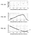
- FIG. 3A is a graph showing a measurement metal temperature distribution with respect to the circumferential-direction position of the bearing pad.
- FIG. 3B is a graph showing an oil-film pressure distribution with respect to the circumferential-direction position of the bearing pad.
- FIG. 3C is a graph showing an oil-film thickness distribution (bearing gap distribution) with respect to the circumferential-direction position of the bearing pad.
- the 0% position in the circumferential direction of the pad corresponds to the position of the upstream end portion 51
- the 100% position in the circumferential direction of the pad corresponds to the position of the downstream end portion 52.
- the measurement metal temperature of the bearing pad 4 is higher at the side of the downstream end portion 52 than at the side of the upstream end portion 51 in the circumferential direction of the pad.
- the oil-film pressure of the bearing gap 8 is higher at the side of the downstream end portion 52 than at the side of the upstream end portion 51 in the circumferential direction of the pad.
- the oil-film thickness of the bearing gap 8 is the greatest at the upstream end portion 51 and gradually decreases toward the downstream end portion 52, in the circumferential direction of the pad, and a wedge-shaped oil film is formed in the bearing gap 8.
- the lubricant oil is drawn into the bearing gap 8 by rotation of the rotor 10, so that the bearing gap 8 has a wedge shape.
- the bearing gap 8 having an appropriate wedge shape normally maintains the oil-film pressure of the bearing gap 8 to be appropriate and keeps the bearing load capacity of the tilting-pad bearing 1 to be high.
- pressure deformation may also be the cause of deformation of the bearing pad 4.
- the bearing pad 4 is supported by the pivot 3 at the back surface 6, and the part other than the pivot 3 is free.
- the part other than the pivot 3 may warp in a direction away from the rotor 10.
- the bearing gap 8 may fail to have an appropriate wedge shape in the operation time, and particularly in the region at the side of the downstream end portion 52 indicated by the reference numeral 60 in FIG. 3C , the bearing gap 8 may become larger than a design value.
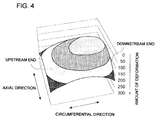
- FIG. 4 is a diagram illustrating a deformation distribution of the bearing-pad surface 5 obtained by the FEM analysis.
- the drawing shows a distribution of the amount of deformation of the bearing pad surface 5 in the tilting-pad bearing 1 in the operation time illustrated in FIG. 2B .
- the amount of deformation is an absolute value representing a change in the position of the bearing pad surface 5 in the operation time relative to the bearing pad surface 5 in the stop time, in the thickness direction of the bearing pad surface 5.
- the amount of deformation is zero, it means that the position of the bearing pad surface 5 in the operation time has not changed from that in the stop time.
- a region where the amount of deformation is close to zero at the substantially center part of the bearing pad surface 5 is the support point of the pivot 3 and its peripheral region, and is less deformed because the back surface 6 is supported by the pivot 3.
- the side of the downstream end portion 52 warps about the support point of the pivot 3, and the bearing pad surface 5 becomes a curved surface protruding toward the rotor 10.
- the change rate is especially great at the side of the downstream end portion 52, and the bearing gap 8 is wide in the downstream region of the bearing pad 4.
- the increase in the bearing gap 8 in the downstream region of the bearing pad 4 can be seen in the region at the side of the downstream end portion 52 indicated by the reference numeral 60 in the bearing gap distribution illustrated in FIG. 3C .
- the bearing gap 8 between the bearing pad surface 5 and the outer circumferential surface of the rotor 10 in the operation time has a wedge shape.
- the bearing gap 8 widens in the downstream region, where a high oil-film pressure is originally required, due to deformation of the bearing pad 4 caused by thermal deformation or pressure deformation, the bearing load capacity of the tilting-pad bearing 1 may decrease considerably.
- the tilting-pad bearing 1 further includes the following configuration to maintain a high bearing load capacity.
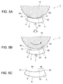
- FIGs. 5A to 5C are each a partial cross-sectional view illustrating the tilting-pad bearing 1 according to one embodiment.
- FIG. 5A illustrates the tilting-pad bearing 1 in the stop time
- FIG. 5B illustrates the tilting-pad bearing 1 in the operation time
- FIG. 5C illustrates a cross section of the bearing pad 4.
- one bearing pad 4 is depicted, whereas other bearing pads 4 are not.
- the cross sections illustrated in the drawings are orthogonal to the axis O (see FIG. 1 ) of the rotor 10 extending from the front to the back of the drawings.
- the tilting-pad bearing 1 is configured such that the bearing pad surface 5 of the bearing pad 4 includes the first region 54 disposed on the upstream side in the rotational direction of the rotor 10 (the direction of the arrow in the drawing) and having the first curvature radius, and the second region 55 disposed on the downstream side of the first region 54 in the rotational direction and having the second curvature radius smaller than the first curvature radius.
- the bearing pad 4 includes the bearing pad surface 5 curved along the outer circumferential surface of the rotor 10 and the back surface 6 curved along the inner circumferential surface of the casing 2.
- the bearing pad surface 5 includes at least the first region 54 having the first curvature radius and the second region 55 having the second curvature radius smaller than the first curvature radius.
- the bearing pad surface 5 has a configuration in which two regions having different curvature radii from each other are disposed adjacently across a boundary 53.
- the bearing pad surface 5 may include three or more regions having different curvature radii.
- the bearing pad surface 5 includes the first region including the upstream end portion 51, the second region including the downstream end portion 52, and the third region disposed between the first region and the second region in the circumferential direction.
- the curvature radius of the third region may be between the curvature radius of the first region and the curvature radius of the second region.
- curvature centers of the first region 54 and the second region 55 are both at the side of the rotor 10.
- the back surface 6 of the bearing pad 4 is curved in the circumferential direction so as to have such a curvature radius that the curvature center is at the side of the rotor 10. Since the back surface 6 is formed along the casing 2, the back surface 6 may have a constant curved surface so that there is one curvature radius in the circumferential direction.
- the tilting-pad bearing 1 may be configured such that, in the stop time, the bearing gap 8 between the upstream end portion 51 and the rotor 10 is greater than the bearing gap 8 between the downstream end portion 52 and the rotor 10.
- deformation of the bearing pad 4 has two major characteristics. One is that the amount of deformation of the bearing pad 4 during operation of the tilting-pad bearing 1 varies between the upstream side and the downstream side, and the other one is that the downstream end portion 52 of the bearing pad surface 5 deforms to warp in a direction away from the rotor 10.
- the bearing pad surface 5 includes the first region 54 disposed on the upstream side in the rotational direction of the rotor 10 and having the first curvature radius, and the second region 55 disposed on the downstream side of the first region 54 in the rotational direction and having the second curvature radius smaller than the first curvature radius.
- the curvature radius varies between the downstream side, where the amount of deformation of the bearing pad 4 is large, and the upstream side, where the amount of deformation is small, it is easy to set an appropriate bearing gap 8 corresponding to the amount of deformation of the bearing pad 4 at each of the upstream side and the downstream side.
- the second curvature radius is smaller than the first curvature radius, it is possible to maintain the bearing gap 8 at the downstream side to be appropriate even if the downstream end portion 52 warps in a direction away from the rotor 10 due to deformation of the bearing pad 4.
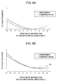
- FIGs. 6A and 6B are graphs comparing the oil-film thickness of the tilting-pad bearing 1 in the embodiment illustrated in FIG. 5 with that of the tilting-pad bearing 1 in the comparative example illustrated in FIG. 2 , during the stop time and the operation time, respectively.
- FIG. 6A is a graph showing the oil-film thickness of the tilting-pad bearing 1 in the present embodiment and the comparative example during the stop time.
- FIG. 6B is a graph showing the oil-film thickness of the tilting-pad bearing 1 in the present embodiment and the comparative example during the operation time.
- the circumferential-direction position of the bearing pad is 0° at the pivot position, negative at the side of the upstream end portion 51, and positive at the side of the downstream end portion 52.
- the tilting-pad bearing 1 of the comparative example has an oil-film thickness that reaches its minimum at 0°, which is the pivot position, and increases toward the upstream end portion 51 and the downstream end portion 52.
- the oil-film thickness is greater at the upstream end portion 51 than at downstream end portion 52.
- the tilting-pad bearing 1 of the present embodiment has an oil-film thickness that reaches its minimum at 0°, which is the pivot position, and increases toward the upstream end portion 51 but stays at a substantially constant value at the side of the downstream end portion 52.
- the oil-film thickness is greater at the upstream end portion 51 than at the downstream end portion 52.
- the tilting-pad bearing 1 in the comparative example has an oil-film thickness that decreases toward the downstream end portion 52 from the upstream end portion 51 and the oil-film has a substantially wedge shape, but the oil-film thickness increases in the vicinity of the downstream end portion 52 indicated by the reference numeral 62.
- the tilting-pad bearing 1 in the present embodiment has an oil-film thickness that decreases toward the downstream end portion 52 from the upstream end portion 51, but does not increase in the vicinity of the downstream end portion 52 indicated by the reference numeral 62, and the oil-film thickness is substantially constant in the vicinity of the downstream end portion 52.
- the curvature center of the first region 54 is disposed closer to the upstream end of the bearing pad 4 than the curvature center of the second region 55 is.
- the bearing gap 8 between the rotor 10 and the end (in the configuration example illustrated in FIG. 5 , the downstream end portion 52) of the bearing pad 4 in the circumferential direction in the second region 55 smaller than the bearing gap 8 between the rotor 10 and the end (in the configuration example illustrated in FIG. 5 , the upstream end portion 51) in the circumferential direction of the bearing pad 4 in the first region 54, and to maintain the oil-film pressure at the downstream side of the bearing pad 4.
- the curvature center of the second region may be configured such that the curvature center of the second curvature radius coincides with the axis O (see FIG. 1 ) of the rotor 10. In this way, in the operation time of the tilting-pad bearing 1, it is easier to set the bearing gap between the rotor 10 and the end of the bearing pad 4 in the circumferential direction in the second region 55 to an appropriate size.
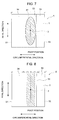
- FIG. 7 is a planar view illustrating the bearing pad 4 according to one embodiment.
- the drawing is a view of the bearing pad 4 as seen from the bearing pad surface 5.
- the pivot 3 is disposed on the back surface 6 not illustrated in the drawing, and thus should not appear in the drawing. However, to help understanding, the support point of the pivot 3 is depicted.
- the first region 54 and the second region 55 are disposed adjacently across a boundary 53 along the axial direction of the tilting-pad bearing 1, and the boundary 53 is disposed outside a contact region 57 where the bearing pad 4 contacts the rotor 10 in the stop time.
- the boundary 53 is formed linearly along the axial direction.
- the boundary 53 may be formed in a linear shape oblique to the axial direction, or in a curve shape substantially along the axial direction.
- the changing point (boundary 53) between the first curvature radius and the second curvature radius has a pointed shape, and a high surface pressure may be applied to the changing point in response to a rotor load applied to the bearing pad 4 when rotation of the rotor 10 is stopped.
- the boundary 53 between the first region 54 and the second region 55 disposed outside the contact region 57 where the bearing pad 4 is in contact with the rotor 10 in the stop time, it is possible to prevent a high surface pressure from being applied to the bearing pad 4 locally when rotation of the rotor 10 is stopped.
- the boundary 53 between the first region 54 and the second region 55 may be disposed on the downstream side of the contact region 57 in the rotational direction. In this way, with the boundary 53 disposed on the downstream side of the contact region 57 between the rotor 10 and the bearing pad 4 in the rotational direction, it is possible to prevent generation of a local surface pressure on the bearing pad 4 in the stop time. Further, if the installation range of the second region 55 having the relatively-small second curvature radius is too broad, it is difficult to set the second curvature radius whereby it is possible to avoid contact between the bearing pad 4 and the outer circumferential surface of the rotor 10 while maintaining the bearing gap 8 to be appropriate.
- the installation range of the second region 55 having the relatively-small second curvature radius is limited to the downstream side of the contact region 57, which makes it easy to set the second curvature radius appropriately taking account of deformation of the downstream end portion 52 of the bearing pad 4.
- FIG. 8 is a planar view illustrating a bearing pad according to another embodiment.
- the drawing is a view of the bearing pad 4 as seen from the bearing pad surface 5.
- the pivot 3 is disposed on the back surface 6 not illustrated in the drawing and thus should not appear in the drawing. However, to help understanding, the support point of the pivot 3 is depicted.
- first region 54 and the second region 55 are disposed adjacently across the boundary 53 along the axial direction of the tilting-pad bearing 1, and the boundary 53 is disposed in a range excluding a range of from ( ⁇ 0 -10°) to ( ⁇ 0 +10°), where ⁇ 0 is the angular position of the pivot in the circumferential direction.
- the boundary 53 is disposed in a range excluding the shaded region in FIG. 8 .
- the boundary 53 between the first region 54 and the second region 55 is disposed in a range excluding a range of from ( ⁇ 0 -10°) to ( ⁇ 0 +10°). Since the bearing pad 4 is mounted to the casing 2 (see FIG. 1 ) about the pivot 3, the rotor 10 contacts the bearing pad 4 in a region centered at the pivot 3. Specifically, according to the above embodiment, the boundary 53 is disposed avoiding a region where the bearing pad 4 and the rotor 10 are to be in contact at a high contact pressure. In this way, it is possible to prevent a high surface pressure from being applied to the bearing pad 4 locally when rotation of the rotor 10 is stopped.
- the boundary 53 between the first region 54 and the second region 55 may be disposed in an angular range larger than ( ⁇ 0 +10°).
- the angular range larger than ( ⁇ 0 +10°) is a range on the right side of the boundary 53.
- the tilting-pad bearing 1 may further include the following configuration to maintain a high bearing load capacity.
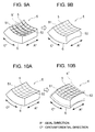
- FIG. 9 is a perspective view of the bearing pad 4 in another embodiment.
- FIG. 9A illustrates the bearing pad 4 in the stop time and
- FIG. 9B illustrates the bearing pad 4 in the operation time.
- FIG. 9B illustrates the bearing pad 4 after deformation due to thermal deformation and pressure deformation.
- the bearing pad 4 is configured such that the bearing pad surface 5 has a concave shape in the axial direction of the tilting-pad bearing 1, at least in the stop time of the rotor 10.
- a bearing pad surface 5' not formed in a concave shape is depicted for comparison.
- the bearing pad surface 5' is represented by imaginary lines as being formed linearly in the axial direction.
- the bearing pad 4 according to another embodiment is configured such that the bearing pad surface 5 has a concave shape in the axial direction of the tilting-pad bearing 1, in a cross section along the axial direction.
- the bearing pad surface 5 may have an amount of concave that is set in accordance with the amount of deformation of the bearing pad 4 due to thermal deformation and pressure deformation.
- the amount of concave may be set for each position in the circumferential direction or the axial direction of the bearing pad surface 5 on the basis of a deformation distribution of the bearing pad surface 5 obtained in advance by the FEM analysis or the like.
- FIGs. 10A and 10B are each a perspective view of the bearing pad 4 in a comparative example.
- FIG. 10A illustrates the bearing pad 4 in the stop time and
- FIG. 10B illustrates the bearing pad 4 in the operation time.
- the bearing pad surface 5 has a concave shape in the axial direction of the tilting-pad bearing 1, at least in the stop time of the rotor 10, which makes it possible to maintain the bearing gap 8 to be appropriate.
- bearing pad surface 5 may be formed in a concave shape such that a center region is disposed farther from the rotor 10 than the end portions in the axial direction are.
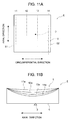
- FIG. 11A is a planar view illustrating the bearing pad 4 according to another embodiment.
- the drawing is a view of the bearing pad 4 as seen from the bearing pad surface 5.
- the pivot 3 is disposed on the back surface 6 not illustrated in the drawing and thus should not appear in the drawing.
- FIG. 11B is a diagram illustrating cross sections of the bearing pad 4 at respective cutting planes 11 to 14 in FIG. 11A .
- the cutting planes 11 to 14 are positioned in order from the side of the upstream end portion 51 to the side of the downstream end portion 52 in FIG. 11A .
- the cutting plane 11 is the closest to the upstream end portion 51 and the cutting plane 14 is the closest to the downstream end portion 52, among the cutting planes.
- Each of the cutting planes 11 to 14 is a cross section along the axial direction.
- the bearing pad surface 11a is the bearing pad surface 5 in a cross section of the bearing pad 4 taken along the cutting plane 11
- the bearing pad surface 12a is the bearing pad surface 5 in a cross section of the bearing pad 4 taken along the cutting plane 12
- the bearing pad surface 13a is the bearing pad surface 5 in a cross section of the bearing pad 4 taken along the cutting plane 13
- the bearing pad surface 14a is the bearing pad surface 5 in a cross section of the bearing pad 4 taken along the cutting plane 14.
- the cutting planes 11, 12 are disposed on the upstream side of the pivot 3
- the cutting planes 13, 14 are disposed on the downstream side of the pivot 3.
- the bearing pad 4 in another embodiment is configured such that the amount of concave in the axial direction of the bearing pad surface 5 is larger at the downstream side of the pivot 3 in the rotational direction than at the upstream side of the pivot 3 in the rotational direction.
- the amount of concave gradually increases in the axial direction of the bearing pad surface 5 from the upstream side toward the downstream side of the bearing pad 4.
- the amount of concave of the bearing pad surface 5 in each cutting plane is not limited to the present configuration. Specifically, the magnitude relationship of the amount of concave between the bearing pad surfaces 11a, 12a of the cutting planes 11, 12 on the upstream side of the pivot 3 is not limited.
- the magnitude relationship of the amount of concave between the bearing pad surfaces 13a, 14a of the cutting planes 13, 14 on the downstream side of the pivot 3 is not limited.
- the bearing pad surface 13a at the cutting plane 13 closer to the upstream side than the bearing pad surface 14a of the cutting plane 14 at the most downstream side is may have a larger amount of concave in the axial direction.
- a relationship is maintained that the amount of concave of the bearing pad surface 5 at a downstream position of the pivot 3 is larger than the amount of concave of the bearing pad surface 5 at an upstream side of the pivot 3.
- the bearing gap 8 on the downstream side of the pivot 3 becomes small.
- the temperature of the bearing pad surface 5 on the downstream side of the pivot 3 is likely to increase due to friction heat between the bearing pad surface 5 and the lubricant oil trying to flow through the narrow bearing gap 8.
- the amount of deformation of the bearing pad 4 is relatively large.
- FIGs. 5 , 7, and 8 is described as being different from that in FIGs. 9 , 11A, and 11B , these embodiments may be combined.
- an expression of relative or absolute arrangement such as “in a direction”, “along a direction”, “parallel”, “orthogonal”, “centered”, “concentric” and “coaxial” shall not be construed as indicating only the arrangement in a strict literal sense, but also includes a state where the arrangement is relatively displaced by a tolerance, or by an angle or a distance whereby it is possible to achieve the same function.
- an expression of an equal state such as “same” “equal” and “uniform” shall not be construed as indicating only the state in which the feature is strictly equal, but also includes a state in which there is a tolerance or a difference that can still achieve the same function.
- an expression of a shape such as a rectangular shape or a cylindrical shape shall not be construed as only the geometrically strict shape, but also includes a shape with unevenness or chamfered corners within the range in which the same effect can be achieved.
Landscapes
- Engineering & Computer Science (AREA)
- General Engineering & Computer Science (AREA)
- Mechanical Engineering (AREA)
- Chemical & Material Sciences (AREA)
- Oil, Petroleum & Natural Gas (AREA)
- Physics & Mathematics (AREA)
- Fluid Mechanics (AREA)
- Sliding-Contact Bearings (AREA)
Applications Claiming Priority (2)
| Application Number | Priority Date | Filing Date | Title |
|---|---|---|---|
| JP2014235423A JP2016098888A (ja) | 2014-11-20 | 2014-11-20 | ティルティングパッド軸受 |
| PCT/JP2015/052107 WO2016080000A1 (ja) | 2014-11-20 | 2015-01-27 | ティルティングパッド軸受 |
Publications (2)
| Publication Number | Publication Date |
|---|---|
| EP3045751A1 true EP3045751A1 (de) | 2016-07-20 |
| EP3045751A4 EP3045751A4 (de) | 2016-08-03 |
Family
ID=56013569
Family Applications (1)
| Application Number | Title | Priority Date | Filing Date |
|---|---|---|---|
| EP15823303.1A Withdrawn EP3045751A4 (de) | 2014-11-20 | 2015-01-27 | Kippsegmentlager |
Country Status (5)
| Country | Link |
|---|---|
| US (1) | US9618036B2 (de) |
| EP (1) | EP3045751A4 (de) |
| JP (1) | JP2016098888A (de) |
| CN (1) | CN106170633A (de) |
| WO (1) | WO2016080000A1 (de) |
Families Citing this family (4)
| Publication number | Priority date | Publication date | Assignee | Title |
|---|---|---|---|---|
| JP6725438B2 (ja) | 2017-02-23 | 2020-07-15 | 三菱日立パワーシステムズ株式会社 | 軸受装置及び回転機械 |
| CN108775333B (zh) * | 2018-07-27 | 2024-03-08 | 贵州伟昭科技有限责任公司 | 一种可在线控制的动静压轴承及其控制方法 |
| CN109058304A (zh) * | 2018-10-18 | 2018-12-21 | 上海毕森流体设备有限公司 | 一种节油降温的可倾瓦轴承结构 |
| AT522164B1 (de) | 2019-03-07 | 2020-09-15 | Miba Gleitlager Austria Gmbh | Gleitlagerung |
Family Cites Families (25)
| Publication number | Priority date | Publication date | Assignee | Title |
|---|---|---|---|---|
| NL289635A (de) * | 1900-01-01 | |||
| FR1353661A (fr) * | 1963-01-19 | 1964-02-28 | Rateau Soc | Perfectionnement aux paliers à gaz |
| DE2802076A1 (de) * | 1978-01-18 | 1979-07-19 | Jerome Greene | Hydrodynamisches lager |
| DE2802098A1 (de) * | 1978-01-18 | 1979-07-19 | Jerome Greene | Hydrodynamisches lager |
| JPS58102819A (ja) | 1981-12-11 | 1983-06-18 | Toshiba Corp | テイルテイングパツド軸受 |
| JPS58149415A (ja) | 1982-02-26 | 1983-09-05 | Hitachi Ltd | 制振軸受 |
| JPS58180816A (ja) | 1982-04-19 | 1983-10-22 | Hitachi Ltd | テイルテイングパツド軸受 |
| EP0130330B1 (de) * | 1983-07-01 | 1987-02-18 | BBC Aktiengesellschaft Brown, Boveri & Cie. | Radialgleitlager |
| JPS6353915U (de) * | 1986-09-29 | 1988-04-11 | ||
| GB2197915B (en) * | 1986-11-19 | 1990-11-14 | Rolls Royce Plc | Improvements in or relating to fluid bearings |
| US5743654A (en) * | 1987-05-29 | 1998-04-28 | Kmc, Inc. | Hydrostatic and active control movable pad bearing |
| JPH0369713U (de) * | 1989-11-13 | 1991-07-11 | ||
| JP3377612B2 (ja) * | 1994-07-27 | 2003-02-17 | 三菱重工業株式会社 | 動圧気体ジャーナル軸受 |
| US5772335A (en) * | 1997-03-31 | 1998-06-30 | Whm Holding Company | Self-stabilizing, true-tilting pad with abruptly-stepped pocket for journal bearing |
| JP2002155945A (ja) * | 2000-11-20 | 2002-05-31 | Daido Metal Co Ltd | 軸支承部材 |
| DE10225008A1 (de) * | 2002-06-06 | 2003-12-24 | Main Metall Giesserei Fritz Sc | Gleitlager |
| JP2004301258A (ja) * | 2003-03-31 | 2004-10-28 | Toshiba Corp | ジャーナル軸受 |
| JP4930290B2 (ja) * | 2007-09-04 | 2012-05-16 | 株式会社日立プラントテクノロジー | ティルティングパッド型ジャーナル軸受 |
| JP2009168205A (ja) | 2008-01-18 | 2009-07-30 | Mitsubishi Heavy Ind Ltd | ティルティングパッド軸受 |
| JP2011179548A (ja) | 2010-02-26 | 2011-09-15 | Mitsubishi Heavy Ind Ltd | ティルティングパッド軸受装置 |
| JP5767884B2 (ja) * | 2011-07-27 | 2015-08-26 | 株式会社東芝 | ティルティングパッドジャーナル軸受および蒸気タービン |
| CN202176616U (zh) * | 2011-08-02 | 2012-03-28 | 无锡杰尔压缩机有限公司 | 一种可倾瓦径向轴承的轴瓦结构 |
| CN102322476B (zh) * | 2011-09-19 | 2012-10-31 | 重庆大学 | 可倾瓦式水润滑橡胶合金轴承 |
| JP6053413B2 (ja) | 2012-09-18 | 2016-12-27 | 三菱日立パワーシステムズ株式会社 | 軸受監視システム、回転機械、及び軸受の監視方法 |
| JP6332919B2 (ja) | 2013-01-31 | 2018-05-30 | 三菱重工業株式会社 | ティルティングパッド軸受装置 |
-
2014
- 2014-11-20 JP JP2014235423A patent/JP2016098888A/ja active Pending
-
2015
- 2015-01-27 CN CN201580001447.3A patent/CN106170633A/zh active Pending
- 2015-01-27 US US14/911,060 patent/US9618036B2/en not_active Expired - Fee Related
- 2015-01-27 WO PCT/JP2015/052107 patent/WO2016080000A1/ja not_active Ceased
- 2015-01-27 EP EP15823303.1A patent/EP3045751A4/de not_active Withdrawn
Also Published As
| Publication number | Publication date |
|---|---|
| WO2016080000A1 (ja) | 2016-05-26 |
| CN106170633A (zh) | 2016-11-30 |
| US20160169276A1 (en) | 2016-06-16 |
| JP2016098888A (ja) | 2016-05-30 |
| US9618036B2 (en) | 2017-04-11 |
| EP3045751A4 (de) | 2016-08-03 |
Similar Documents
| Publication | Publication Date | Title |
|---|---|---|
| EP3032122B1 (de) | Kippsegmentgleitlager | |
| RU2717302C1 (ru) | Подшипник с самоустанавливающимися сегментными подушками и способ его изготовления | |
| JP5767884B2 (ja) | ティルティングパッドジャーナル軸受および蒸気タービン | |
| US11193528B2 (en) | Bearing pad for tilting-pad bearing, tilting-pad bearing, and rotary machine | |
| EP2850327B1 (de) | Ölgeschmiertes radialgleitlager | |
| US9618036B2 (en) | Tilting-pad bearing | |
| CN106704361A (zh) | 具有自引导冷却的箔片气体轴承组件 | |
| JP6615573B2 (ja) | スラストフォイル軸受 | |
| EP2757275B1 (de) | Hochfeste Halterung für Foliengleitlager | |
| JP6820314B2 (ja) | オフセット調整式ピボットジャーナルパッド | |
| JP5773806B2 (ja) | スラスト軸受 | |
| KR102240987B1 (ko) | 베어링 장치 및 회전기계 | |
| WO2017086190A1 (ja) | フォイル軸受 | |
| JP2015209898A (ja) | ジャーナル軸受装置及びこれを備えた回転機械 | |
| JP6818668B2 (ja) | ティルティングパッドジャーナル軸受及びこれを用いた遠心圧縮機 | |
| JP6979332B2 (ja) | ティルティングパッド軸受 | |
| EP3249172B1 (de) | Dichtungsvorrichtung für turbine, turbine und dünne platte für dichtungsvorrichtung | |
| EP2679842A1 (de) | Hydrodynamisches Radiallager, insbesondere zur Verwendung in einer Dampfturbine und anderen rotierenden Geräten | |
| EP3249267B1 (de) | Dichtungsvorrichtung für turbine, turbine und dünne platte für dichtungsvorrichtung | |
| JP2015124775A (ja) | 軸受装置、回転機械 | |
| JP2013167321A (ja) | ジャーナル軸受 | |
| JP2016118151A (ja) | 軸受装置、回転機械 |
Legal Events
| Date | Code | Title | Description |
|---|---|---|---|
| PUAI | Public reference made under article 153(3) epc to a published international application that has entered the european phase |
Free format text: ORIGINAL CODE: 0009012 |
|
| 17P | Request for examination filed |
Effective date: 20160126 |
|
| AK | Designated contracting states |
Kind code of ref document: A1 Designated state(s): AL AT BE BG CH CY CZ DE DK EE ES FI FR GB GR HR HU IE IS IT LI LT LU LV MC MK MT NL NO PL PT RO RS SE SI SK SM TR |
|
| AX | Request for extension of the european patent |
Extension state: BA ME |
|
| A4 | Supplementary search report drawn up and despatched |
Effective date: 20160701 |
|
| RIC1 | Information provided on ipc code assigned before grant |
Ipc: F16C 33/10 20060101ALI20160627BHEP Ipc: F16C 17/22 20060101ALN20160627BHEP Ipc: F16C 17/03 20060101AFI20160627BHEP |
|
| STAA | Information on the status of an ep patent application or granted ep patent |
Free format text: STATUS: THE APPLICATION HAS BEEN WITHDRAWN |
|
| 18W | Application withdrawn |
Effective date: 20170712 |