EP3045340A1 - Anzeigevorrichtung für ein fahrzeug - Google Patents
Anzeigevorrichtung für ein fahrzeug Download PDFInfo
- Publication number
- EP3045340A1 EP3045340A1 EP15202055.8A EP15202055A EP3045340A1 EP 3045340 A1 EP3045340 A1 EP 3045340A1 EP 15202055 A EP15202055 A EP 15202055A EP 3045340 A1 EP3045340 A1 EP 3045340A1
- Authority
- EP
- European Patent Office
- Prior art keywords
- securing
- panel
- metallic plate
- connecting metallic
- display device
- Prior art date
- Legal status (The legal status is an assumption and is not a legal conclusion. Google has not performed a legal analysis and makes no representation as to the accuracy of the status listed.)
- Granted
Links
- 238000005452 bending Methods 0.000 claims description 9
- 230000035939 shock Effects 0.000 abstract description 10
- 210000004027 cell Anatomy 0.000 description 4
- 239000004973 liquid crystal related substance Substances 0.000 description 4
- 239000007769 metal material Substances 0.000 description 3
- 230000005489 elastic deformation Effects 0.000 description 2
- 229910000906 Bronze Inorganic materials 0.000 description 1
- 229910000861 Mg alloy Inorganic materials 0.000 description 1
- OAICVXFJPJFONN-UHFFFAOYSA-N Phosphorus Chemical compound [P] OAICVXFJPJFONN-UHFFFAOYSA-N 0.000 description 1
- 229910000639 Spring steel Inorganic materials 0.000 description 1
- 239000010974 bronze Substances 0.000 description 1
- KUNSUQLRTQLHQQ-UHFFFAOYSA-N copper tin Chemical compound [Cu].[Sn] KUNSUQLRTQLHQQ-UHFFFAOYSA-N 0.000 description 1
- 210000002858 crystal cell Anatomy 0.000 description 1
- 239000002184 metal Substances 0.000 description 1
- 229910052751 metal Inorganic materials 0.000 description 1
- 238000000465 moulding Methods 0.000 description 1
- 230000000717 retained effect Effects 0.000 description 1
- 238000000926 separation method Methods 0.000 description 1
- 239000010935 stainless steel Substances 0.000 description 1
- 229910001220 stainless steel Inorganic materials 0.000 description 1
Images


Classifications
-
- B—PERFORMING OPERATIONS; TRANSPORTING
- B60—VEHICLES IN GENERAL
- B60R—VEHICLES, VEHICLE FITTINGS, OR VEHICLE PARTS, NOT OTHERWISE PROVIDED FOR
- B60R11/00—Arrangements for holding or mounting articles, not otherwise provided for
- B60R11/02—Arrangements for holding or mounting articles, not otherwise provided for for radio sets, television sets, telephones, or the like; Arrangement of controls thereof
- B60R11/0229—Arrangements for holding or mounting articles, not otherwise provided for for radio sets, television sets, telephones, or the like; Arrangement of controls thereof for displays, e.g. cathodic tubes
- B60R11/0235—Arrangements for holding or mounting articles, not otherwise provided for for radio sets, television sets, telephones, or the like; Arrangement of controls thereof for displays, e.g. cathodic tubes of flat type, e.g. LCD
-
- B—PERFORMING OPERATIONS; TRANSPORTING
- B60—VEHICLES IN GENERAL
- B60K—ARRANGEMENT OR MOUNTING OF PROPULSION UNITS OR OF TRANSMISSIONS IN VEHICLES; ARRANGEMENT OR MOUNTING OF PLURAL DIVERSE PRIME-MOVERS IN VEHICLES; AUXILIARY DRIVES FOR VEHICLES; INSTRUMENTATION OR DASHBOARDS FOR VEHICLES; ARRANGEMENTS IN CONNECTION WITH COOLING, AIR INTAKE, GAS EXHAUST OR FUEL SUPPLY OF PROPULSION UNITS IN VEHICLES
- B60K35/00—Instruments specially adapted for vehicles; Arrangement of instruments in or on vehicles
- B60K35/20—Output arrangements, i.e. from vehicle to user, associated with vehicle functions or specially adapted therefor
-
- B—PERFORMING OPERATIONS; TRANSPORTING
- B60—VEHICLES IN GENERAL
- B60K—ARRANGEMENT OR MOUNTING OF PROPULSION UNITS OR OF TRANSMISSIONS IN VEHICLES; ARRANGEMENT OR MOUNTING OF PLURAL DIVERSE PRIME-MOVERS IN VEHICLES; AUXILIARY DRIVES FOR VEHICLES; INSTRUMENTATION OR DASHBOARDS FOR VEHICLES; ARRANGEMENTS IN CONNECTION WITH COOLING, AIR INTAKE, GAS EXHAUST OR FUEL SUPPLY OF PROPULSION UNITS IN VEHICLES
- B60K35/00—Instruments specially adapted for vehicles; Arrangement of instruments in or on vehicles
- B60K35/50—Instruments characterised by their means of attachment to or integration in the vehicle
-
- B—PERFORMING OPERATIONS; TRANSPORTING
- B60—VEHICLES IN GENERAL
- B60R—VEHICLES, VEHICLE FITTINGS, OR VEHICLE PARTS, NOT OTHERWISE PROVIDED FOR
- B60R21/00—Arrangements or fittings on vehicles for protecting or preventing injuries to occupants or pedestrians in case of accidents or other traffic risks
- B60R21/02—Occupant safety arrangements or fittings, e.g. crash pads
- B60R21/055—Padded or energy-absorbing fittings, e.g. seat belt anchors
-
- B—PERFORMING OPERATIONS; TRANSPORTING
- B60—VEHICLES IN GENERAL
- B60K—ARRANGEMENT OR MOUNTING OF PROPULSION UNITS OR OF TRANSMISSIONS IN VEHICLES; ARRANGEMENT OR MOUNTING OF PLURAL DIVERSE PRIME-MOVERS IN VEHICLES; AUXILIARY DRIVES FOR VEHICLES; INSTRUMENTATION OR DASHBOARDS FOR VEHICLES; ARRANGEMENTS IN CONNECTION WITH COOLING, AIR INTAKE, GAS EXHAUST OR FUEL SUPPLY OF PROPULSION UNITS IN VEHICLES
- B60K2360/00—Indexing scheme associated with groups B60K35/00 or B60K37/00 relating to details of instruments or dashboards
- B60K2360/60—Structural details of dashboards or instruments
- B60K2360/65—Features of dashboards
- B60K2360/652—Crash protection features
-
- B—PERFORMING OPERATIONS; TRANSPORTING
- B60—VEHICLES IN GENERAL
- B60K—ARRANGEMENT OR MOUNTING OF PROPULSION UNITS OR OF TRANSMISSIONS IN VEHICLES; ARRANGEMENT OR MOUNTING OF PLURAL DIVERSE PRIME-MOVERS IN VEHICLES; AUXILIARY DRIVES FOR VEHICLES; INSTRUMENTATION OR DASHBOARDS FOR VEHICLES; ARRANGEMENTS IN CONNECTION WITH COOLING, AIR INTAKE, GAS EXHAUST OR FUEL SUPPLY OF PROPULSION UNITS IN VEHICLES
- B60K2360/00—Indexing scheme associated with groups B60K35/00 or B60K37/00 relating to details of instruments or dashboards
- B60K2360/60—Structural details of dashboards or instruments
- B60K2360/68—Features of instruments
-
- B—PERFORMING OPERATIONS; TRANSPORTING
- B60—VEHICLES IN GENERAL
- B60K—ARRANGEMENT OR MOUNTING OF PROPULSION UNITS OR OF TRANSMISSIONS IN VEHICLES; ARRANGEMENT OR MOUNTING OF PLURAL DIVERSE PRIME-MOVERS IN VEHICLES; AUXILIARY DRIVES FOR VEHICLES; INSTRUMENTATION OR DASHBOARDS FOR VEHICLES; ARRANGEMENTS IN CONNECTION WITH COOLING, AIR INTAKE, GAS EXHAUST OR FUEL SUPPLY OF PROPULSION UNITS IN VEHICLES
- B60K2360/00—Indexing scheme associated with groups B60K35/00 or B60K37/00 relating to details of instruments or dashboards
- B60K2360/816—Fastening of displays or touch screens
-
- B—PERFORMING OPERATIONS; TRANSPORTING
- B60—VEHICLES IN GENERAL
- B60R—VEHICLES, VEHICLE FITTINGS, OR VEHICLE PARTS, NOT OTHERWISE PROVIDED FOR
- B60R11/00—Arrangements for holding or mounting articles, not otherwise provided for
- B60R2011/0001—Arrangements for holding or mounting articles, not otherwise provided for characterised by position
- B60R2011/0003—Arrangements for holding or mounting articles, not otherwise provided for characterised by position inside the vehicle
- B60R2011/0005—Dashboard
-
- B—PERFORMING OPERATIONS; TRANSPORTING
- B60—VEHICLES IN GENERAL
- B60R—VEHICLES, VEHICLE FITTINGS, OR VEHICLE PARTS, NOT OTHERWISE PROVIDED FOR
- B60R11/00—Arrangements for holding or mounting articles, not otherwise provided for
- B60R2011/0042—Arrangements for holding or mounting articles, not otherwise provided for characterised by mounting means
- B60R2011/0049—Arrangements for holding or mounting articles, not otherwise provided for characterised by mounting means for non integrated articles
- B60R2011/005—Connection with the vehicle part
- B60R2011/0052—Connection with the vehicle part using screws, bolts, rivets or the like
-
- B—PERFORMING OPERATIONS; TRANSPORTING
- B60—VEHICLES IN GENERAL
- B60R—VEHICLES, VEHICLE FITTINGS, OR VEHICLE PARTS, NOT OTHERWISE PROVIDED FOR
- B60R11/00—Arrangements for holding or mounting articles, not otherwise provided for
- B60R2011/0042—Arrangements for holding or mounting articles, not otherwise provided for characterised by mounting means
- B60R2011/0049—Arrangements for holding or mounting articles, not otherwise provided for characterised by mounting means for non integrated articles
- B60R2011/0064—Connection with the article
- B60R2011/0066—Connection with the article using screws, bolts, rivets or the like
Definitions
- the present invention relates to an on-vehicle display device in which, for example, a liquid crystal display panel is mounted on a supporting member. More particularly, the present invention relates to an on-vehicle display device that is formed such that, when an external force acts upon a supporting member and a fracture surface is produced, the fracture surface is not exposed in a dangerous direction.
- on-vehicle display devices a type in which a display panel is set in a raised position upwardly from an instrument panel or a dashboard, and a type in which, by a mechanism using a motor, a display panel is set in a raised position upwardly from an instrument panel or a dashboard only when it is used are used.
- the supporting member that supports the display panel may be fractured.
- an easily fracturing portion is formed at a supporting plate portion that supports a display panel, and the supporting plate portion can be fractured starting from the easily fracturing portion when shock is applied.
- Two end portions of each of two tension coil springs are secured to the supporting plate portion with the easily fracturing portion being interposed between the two tension coil springs.
- an object of the present invention to provide an on-vehicle display device having a structure in which, when a supporting member on which a display panel is mounted is fractured due to shock, a portion that supports the display panel tends to be restored to an orientation state that is close to its original orientation state.
- the invention relates to an on-vehicle display device according to claim 1.
- an on-vehicle display device including a display panel and a supporting member on which the display panel is mounted, the supporting member including a panel supporting portion that supports the display panel and a base portion that supports the panel supporting portion.
- the supporting member further includes a preferentially fracturing portion that is formed between the panel supporting portion and the base portion. Preferably it has lower bending strength than the panel supporting portion and the base portion.
- a connecting metallic plate that extends from the base portion to the panel supporting portion is provided at the supporting member, and the connecting metallic plate is secured to the base portion at a first securing section, is secured to the panel supporting portion at a second securing section, and is elastically deformable in a bending direction.
- the connecting metallic plate includes a bend portion that reduces a distance between the first securing section and the second securing section.
- the on-vehicle display device may be such that, when a force in a direction that moves the first securing section and the second securing section away from each other acts, the bend portion is stretched to allow a distance between the first securing section and the second securing section to increase.
- the bend portion may be bent into a V shape.
- the bend portion may be curved in a convex form.
- the bend portion is formed closer to the first securing section than the preferentially fracturing portion.
- the second securing section includes a screw securing portion where the connecting metallic plate is secured to the panel supporting portion and a protrusion-and-recess fitting portion where a protrusion of the panel supporting portion is fitted to a fitting hole of the connecting metallic plate.
- the connecting metallic plate when shock is applied to the panel supporting portion that supports the display panel and the supporting member is fractured at the preferentially fracturing portion, the connecting metallic plate stretches at the bend portion, so that the panel supporting portion is movable in a direction away from the base portion. Therefore, the connecting metallic plate is less likely to be cut, so that the panel supporting portion can be prevented from being separated and driven out.
- the connecting metallic plate that supports the separated panel supporting portion when bent, the panel supporting portion restores itself above the base portion by an elastic restoring force of the connecting metallic plate. Therefore, it is possible to prevent the fracture surface of the preferentially fracturing portion from facing the interior of a vehicle, and to make it less dangerous for an occupant.
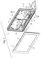
- An on-vehicle display device 1 shown in Fig. 1 includes a display panel 2.
- the display panel 2 is a combination of a display cell 3, a backlight, a transparent surface panel 4, and a capacitive touch pad or a resistance change touch pad.
- the display cell 3 is a color liquid crystal cell or an EL display cell. If a color liquid crystal panel is used, the backlight illuminates the color liquid crystal panel from a back side thereof.
- the surface panel 4 is disposed in front of a screen 3a of the display cell 3. The touch pad is placed upon the surface panel 4.
- the display panel 2 is mounted on a supporting member 10.
- the supporting member 10 is formed of a metallic material that tends to be fractured when shock is applied thereto.
- the supporting member 10 is formed by die-cast molding by using, for example, a magnesium alloy.
- a panel supporting portion 11 and a base portion 12 are integrated with each other.
- a curved portion (connecting portion) 13 is formed at an intermediate portion between the panel supporting portion 11 and the base portion 12 so as to be integrated therewith.
- the panel supporting portion 11 is set in a raised position with respect to the base portion 12.
- the panel supporting portion 11 includes a mounting surface 11a, which is a front surface, and edges 11b that rise towards the front from four sides along a periphery of the mounting surface 11a.
- the mounting surface 11a is integrated with the edges 11b.
- the display panel 2 is set on the mounting surface 11a, which is the front surface of the panel supporting portion 11, with the four sides along the periphery of the mounting surface 11a being surrounded by the edges 11b.
- the display panel 2 is secured to the panel supporting portion 11 with, for example, securing screws or securing metal parts.
- the base portion 12 is set on a dashboard or an instrument panel in the interior of a vehicle, the panel supporting portion 11 is secured in a raised position, and the screen 3a of the display panel 2 faces the interior of the vehicle.
- the base portion 12 is supported by a raising-and-lowering mechanism that is provided, for example, in the interior of a dashboard; the base portion 12 is accommodated in the interior of the dashboard when the on-vehicle display device 1 is not used; and the panel supporting portion 11 and the display panel 2 are raised by the raising-and-lowering mechanism and are set in a raised position on the dashboard when the on-vehicle display device 1 is used.
- a preferentially fracturing portion 14 is provided at the curved portion 13 of the supporting member 10.
- the thickness of a portion of the preferentially fracturing portion 14 is less than the thicknesses of other regions.
- the preferentially fracturing portion 14 may have intermittently formed through holes.
- the supporting member 10 is such that, when shock is applied to the panel supporting portion 11, the supporting member 10 is capable of being fractured at the preferentially fracturing portion 14.
- each connecting metallic plate 20 is formed of an elastic metallic material that exhibits a relatively large elastic restoring force in a bending direction.
- Each connecting metallic plate 20 is desirably formed of what is called a leaf spring metallic material, such as a stainless-steel spring steel plate and a phosphor bronze plate.
- each connecting metallic plate 20 includes a first securing portion 21 and a second securing portion 22.
- Each first securing portion 21 has a securing hole 21a for securing the corresponding connecting metallic plate 20 to the base portion 12.
- Each second securing portion 22 has a securing hole 22a and a fitting hole 22b for securing the corresponding connecting metallic plate 20 to the panel supporting portion 11.
- Each connecting metallic plate 20 includes an intermediate portion 23 between the first securing portion 21 and the second securing portion 22.
- Each intermediate portion 23 includes a bend portion 24.
- Each bend portion 24 is formed by deforming a metallic plate such that the distance between the securing hole 21a of the first securing portion and the securing hole 22a of the second securing portion, that is, the distance along a plate surface of the metallic plate excluding the bend portion 24, is reduced.
- each bend portion 24 is V-shaped. However, as in other embodiments described later, each bend portion 24 need not be V-shaped.
- a downwardly extending securing base 31 is integrated with the base portion 12 of the supporting member 10, and has internally threaded holes 31a.
- a securing screw 32 is inserted into the securing hole 21a of the first securing portion 21 of each connecting metallic plate 20, and is driven into and tightened in the internally threaded hole 31a, so that each first securing portion 21 is firmly secured to the securing base 31.
- the securing screws 32, the securing holes 21a, and the internally threaded holes 31a form first securing sections 30 for securing the connecting metallic plates 20 to a lower side of the base portion 12.
- a slightly inwardly formed securing surface 11c is formed at the mounting surface 11a of the panel supporting portion 11 of the supporting member 10.
- Two pairs of supporting protrusions 41 and 41 are formed such that the supporting protrusions 41 and 41 of each pair are formed apart from each other in a left-right direction so as to integrally protrude from the securing surface 11c.
- a securing base 42 is formed between the supporting protrusions 41 and 41 of each pair so as to protrude forward.
- Each securing base 42 has an internally threaded hole 42a.
- Protrusions 43 are integrally formed with the panel supporting portion 11 at locations that are situated below the respective securing bases 42.
- each connecting metallic plate 20 is mounted between the supporting protrusions 41 and 41 at the securing surface 11c of the panel supporting portion 11.
- Retaining portions 22c and 22c protruding towards the left and right are integrally formed with an end portion of each second securing portion 22.
- the two pairs of retaining portions 22c and 22c are retained at top end surfaces of the two pairs of supporting protrusions 41 and 41.
- each fitting hole 22b is fitted to the corresponding protrusion 43 to form a protrusion-and-recess fitting portion.
- each securing screw 44 is inserted into the corresponding securing hole 22a, and is driven into the corresponding internally threaded hole 42a, so that each second securing portion 22 is firmly tightened and secured by a screw securing portion.
- the two pairs of supporting protrusions 41 and 41, the protrusions 43, the internally threaded holes 42a, the securing holes 22a, the fitting holes 22b, the two pairs of retaining portions 22c and 22c, and the securing screws 44 form second securing sections 40 for securing the second securing portions 22 to the front surface of the panel supporting portion 11.
- each connecting metallic plate 20 extends along the mounting surface 11a of the panel supporting portion 11 from the lower side of the base portion 12. Excluding the first securing sections 30 and the second securing sections 40, the connecting metallic plates 20 do not contact the supporting member 10, and are slightly separated from the supporting member 10 along a front surface of the supporting member 10. In particular, at a portion where the preferentially fracturing portion 14 is formed, each connecting metallic plate 20 is slightly separated from the curved portion 13 of the supporting member 13.
- the bend portion 24 is positioned closer to the corresponding first securing section 30 than the preferentially fracturing portion 14, and faces the lower side of the base portion 12.
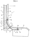
- Fig. 4 shows states of actions when, from a front side, a large force acts upon the panel supporting portion 11 that supports the display panel 2.
- each second securing section 40 since the second securing portion 22 is firmly secured to the panel supporting portion 11, even if the preferentially fracturing portion 14 is fractured and the force in the direction (ii) acts upon the panel supporting portion 11, the second securing portion 22 is not easily removed from the panel supporting portion 11.
- each bend portion 24 is an elastic deformation. Therefore, after each bend portion 24 has been stretched by the pulling force, each bend portion 24 is restored to its original shape. Depending upon the strength of the force in the direction (ii), each bend portion 24 may partly undergo plastic deformation. In either case, since each connecting metallic plate 20 is formed from a metallic plate that exhibits a strong elastic restoring force in the bending direction as a whole, by the elastic force of each connecting metallic plate 20, a large restoring force in a direction (iii) acts upon the panel supporting portion 11 that has fallen to the position indicated by the broken lines in Fig. 4 , so that the panel supporting portion 11 can be restored to the raised position indicated by the solid line in Fig. 4 .
- the panel supporting portion 11 is restored so as to be raised above a fracture surface 14a at a side of the base portion 12. Therefore, the fracture surface 14a of the side of the base portion that has been fractured at the preferentially fracturing portion 14 is prevented from being directly exposed.
- a fracture surface 14b at a side of the panel supporting portion 11 faces downward, so that a portion of the panel supporting portion 11 that is situated forwardly from the fracture surface 14a and a lower end portion of the display panel 2 oppose each other. Therefore, it becomes easier to prevent the danger of the fracture surface 14b directly facing an occupant.
- the bend portion 24 is disposed closer to the corresponding first securing section 30 than the preferentially fracturing portion 14, and is positioned at the lower side of the base portion 12.
- Each bend portion 24 is positioned at the lower side of the base portion 12. Therefore, even if the elasticity of each bend portion 24 is reduced by a pulling force, since each bend portion 24 is positioned at the lower side of the base portion 12 and elastic restoring force can be exhibited at a portion of the metallic plate that exists forwardly from the corresponding bend portion 24 and that supports the panel supporting portion 11, the panel supporting portion 11 tends to be restored to its raised position.
- each bend portion 24 is desirable to dispose each bend portion 24 closer to its corresponding first securing section 30 than the preferentially fracturing portion 14, and at the lower side of the base portion 12.
- Figs. 5 and 6 show other embodiments of the present invention.
- a connecting metallic plate 20A according to a second embodiment shown in Fig. 5 is such that its bend portion 24A is curved in a convex form.
- the connecting metallic plate 20A is stretched, the shape of the bend portion 24A tends to be elastically restored to its original shape.
- a connecting metallic plate 20B according to a third embodiment shown in Fig. 6 is such that its bend portion 24B has V-shaped bending portions that are repeatedly formed.
- a stretching force acts upon the connecting metallic plate 20B, at the bend portion 24B, a separation distance between a first securing section 30 and a second securing section 40 can be increased, as a result of which the connecting metallic plate 20B is even less likely to be cut.
Landscapes
- Engineering & Computer Science (AREA)
- Mechanical Engineering (AREA)
- Chemical & Material Sciences (AREA)
- Combustion & Propulsion (AREA)
- Transportation (AREA)
- Devices For Indicating Variable Information By Combining Individual Elements (AREA)
- Fittings On The Vehicle Exterior For Carrying Loads, And Devices For Holding Or Mounting Articles (AREA)
- Instrument Panels (AREA)
Applications Claiming Priority (1)
| Application Number | Priority Date | Filing Date | Title |
|---|---|---|---|
| JP2015003892A JP6355567B2 (ja) | 2015-01-13 | 2015-01-13 | 車載用表示装置 |
Publications (2)
| Publication Number | Publication Date |
|---|---|
| EP3045340A1 true EP3045340A1 (de) | 2016-07-20 |
| EP3045340B1 EP3045340B1 (de) | 2019-02-06 |
Family
ID=55070747
Family Applications (1)
| Application Number | Title | Priority Date | Filing Date |
|---|---|---|---|
| EP15202055.8A Active EP3045340B1 (de) | 2015-01-13 | 2015-12-22 | Anzeigevorrichtung für ein fahrzeug |
Country Status (3)
| Country | Link |
|---|---|
| EP (1) | EP3045340B1 (de) |
| JP (1) | JP6355567B2 (de) |
| CN (1) | CN105774680B (de) |
Cited By (9)
| Publication number | Priority date | Publication date | Assignee | Title |
|---|---|---|---|---|
| EP3272588A1 (de) * | 2016-07-21 | 2018-01-24 | Faurecia Interieur Industrie | Halterung für vorrichtung, wie einem anzeigemittel |
| WO2020008237A1 (en) * | 2018-07-04 | 2020-01-09 | Bosch Car Multimedia Portugal, S.A. | System carrier for instrument clusters |
| WO2020081407A1 (en) * | 2018-10-18 | 2020-04-23 | Corning Incorporated | High-impact energy absorption connection design for auto interior display module under head form impact |
| WO2020200680A1 (de) * | 2019-04-02 | 2020-10-08 | Volkswagen Aktiengesellschaft | Vorrichtung zur aufnahme einer anzeige-bedieneinrichtung |
| EP3722136A1 (de) * | 2019-04-09 | 2020-10-14 | Volvo Car Corporation | Anzeige in einem nach unten geneigten lenkrad |
| WO2021063854A1 (de) * | 2019-10-02 | 2021-04-08 | Volkswagen Aktiengesellschaft | Positionierungssystem zur positionierung einer anzeigeeinrichtung in einem kraftfahrzeug sowie ein kraftfahrzeug |
| US20220324471A1 (en) * | 2020-10-15 | 2022-10-13 | Denso Ten Limited | On-vehicle device |
| EP4279314A3 (de) * | 2022-05-20 | 2023-12-13 | Continental Automotive Technologies GmbH | Anzeigevorrichtung, armaturentafel und fortbewegungsmittel |
| EP4279315A3 (de) * | 2022-05-20 | 2023-12-20 | Continental Automotive Technologies GmbH | Anzeigevorrichtung, armaturentafel und fortbewegungsmittel |
Families Citing this family (5)
| Publication number | Priority date | Publication date | Assignee | Title |
|---|---|---|---|---|
| JP7055575B2 (ja) | 2019-02-14 | 2022-04-18 | アルパイン株式会社 | 車載用装置 |
| DE102020112133A1 (de) | 2020-05-05 | 2021-11-11 | Kirchhoff Automotive Deutschland Gmbh | Baugruppe für ein Fahrzeug |
| DE102020112131B3 (de) | 2020-05-05 | 2021-03-18 | Kirchhoff Automotive Deutschland Gmbh | Baugruppe für ein Fahrzeug |
| DE102020112132B3 (de) * | 2020-05-05 | 2021-03-18 | Kirchhoff Automotive Deutschland Gmbh | Baugruppe für ein Fahrzeug |
| CN113879123A (zh) * | 2021-09-28 | 2022-01-04 | 岚图汽车科技有限公司 | 一种仪表板的支撑结构、仪表板总成及汽车 |
Citations (2)
| Publication number | Priority date | Publication date | Assignee | Title |
|---|---|---|---|---|
| EP2676847A1 (de) * | 2012-06-21 | 2013-12-25 | Alpine Electronics, Inc. | Fahrzeuginterne Anzeigevorrichtung |
| DE102013003942A1 (de) * | 2013-03-07 | 2014-09-11 | Brose Fahrzeugteile Gmbh & Co. Kommanditgesellschaft, Coburg | Bildschirmträger zur Halterung eines Bildschirms in einem Fahrzeug |
Family Cites Families (4)
| Publication number | Priority date | Publication date | Assignee | Title |
|---|---|---|---|---|
| JP2000330475A (ja) * | 1999-05-24 | 2000-11-30 | Mitsubishi Electric Corp | 車載用表示装置の取付構造 |
| JP4084166B2 (ja) * | 2002-11-13 | 2008-04-30 | 株式会社 日立ディスプレイズ | 画像表示装置 |
| JP5851943B2 (ja) * | 2012-06-13 | 2016-02-03 | アルパイン株式会社 | 車載用表示装置 |
| CN105093604A (zh) * | 2014-04-28 | 2015-11-25 | 厦门歌乐电子企业有限公司 | 一种车载装置 |
-
2015
- 2015-01-13 JP JP2015003892A patent/JP6355567B2/ja active Active
- 2015-12-16 CN CN201510940283.2A patent/CN105774680B/zh active Active
- 2015-12-22 EP EP15202055.8A patent/EP3045340B1/de active Active
Patent Citations (3)
| Publication number | Priority date | Publication date | Assignee | Title |
|---|---|---|---|---|
| EP2676847A1 (de) * | 2012-06-21 | 2013-12-25 | Alpine Electronics, Inc. | Fahrzeuginterne Anzeigevorrichtung |
| JP2014004857A (ja) | 2012-06-21 | 2014-01-16 | Alpine Electronics Inc | 車載用表示装置 |
| DE102013003942A1 (de) * | 2013-03-07 | 2014-09-11 | Brose Fahrzeugteile Gmbh & Co. Kommanditgesellschaft, Coburg | Bildschirmträger zur Halterung eines Bildschirms in einem Fahrzeug |
Cited By (13)
| Publication number | Priority date | Publication date | Assignee | Title |
|---|---|---|---|---|
| FR3054180A1 (fr) * | 2016-07-21 | 2018-01-26 | Faurecia Interieur Industrie | Support pour dispositif, tel un moyen d'affichage |
| EP3272588A1 (de) * | 2016-07-21 | 2018-01-24 | Faurecia Interieur Industrie | Halterung für vorrichtung, wie einem anzeigemittel |
| WO2020008237A1 (en) * | 2018-07-04 | 2020-01-09 | Bosch Car Multimedia Portugal, S.A. | System carrier for instrument clusters |
| CN113039086A (zh) * | 2018-10-18 | 2021-06-25 | 康宁公司 | 头型撞击下的汽车内部显示模块的高冲击能量吸收连接设计 |
| WO2020081407A1 (en) * | 2018-10-18 | 2020-04-23 | Corning Incorporated | High-impact energy absorption connection design for auto interior display module under head form impact |
| WO2020200680A1 (de) * | 2019-04-02 | 2020-10-08 | Volkswagen Aktiengesellschaft | Vorrichtung zur aufnahme einer anzeige-bedieneinrichtung |
| EP3722136A1 (de) * | 2019-04-09 | 2020-10-14 | Volvo Car Corporation | Anzeige in einem nach unten geneigten lenkrad |
| WO2021063854A1 (de) * | 2019-10-02 | 2021-04-08 | Volkswagen Aktiengesellschaft | Positionierungssystem zur positionierung einer anzeigeeinrichtung in einem kraftfahrzeug sowie ein kraftfahrzeug |
| DE102019215197A1 (de) * | 2019-10-02 | 2021-04-08 | Volkswagen Aktiengesellschaft | Positionierungssystem zur Positionierung einer Anzeigeeinrichtung in einem Kraftfahrzeug sowie ein Kraftfahrzeug |
| DE102019215197B4 (de) | 2019-10-02 | 2022-09-29 | Volkswagen Aktiengesellschaft | Positionierungssystem zur Positionierung einer Anzeigeeinrichtung in einem Kraftfahrzeug sowie ein Kraftfahrzeug |
| US20220324471A1 (en) * | 2020-10-15 | 2022-10-13 | Denso Ten Limited | On-vehicle device |
| EP4279314A3 (de) * | 2022-05-20 | 2023-12-13 | Continental Automotive Technologies GmbH | Anzeigevorrichtung, armaturentafel und fortbewegungsmittel |
| EP4279315A3 (de) * | 2022-05-20 | 2023-12-20 | Continental Automotive Technologies GmbH | Anzeigevorrichtung, armaturentafel und fortbewegungsmittel |
Also Published As
| Publication number | Publication date |
|---|---|
| JP6355567B2 (ja) | 2018-07-11 |
| CN105774680A (zh) | 2016-07-20 |
| CN105774680B (zh) | 2020-01-17 |
| JP2016130037A (ja) | 2016-07-21 |
| EP3045340B1 (de) | 2019-02-06 |
Similar Documents
| Publication | Publication Date | Title |
|---|---|---|
| EP3045340B1 (de) | Anzeigevorrichtung für ein fahrzeug | |
| US9933689B2 (en) | Tilt module subassembly and optical image stabilizer comprising it | |
| CN103991367B (zh) | 车辆的门构造 | |
| EP3499343B1 (de) | Elektronische vorrichtung | |
| JP2012054004A (ja) | 照明器具 | |
| CN111559319B (zh) | 车载用装置 | |
| US9623810B2 (en) | Device for positioning and securing a display element and display device | |
| US20130153799A1 (en) | Hydraulic pressure control device | |
| JP6584360B2 (ja) | フィードバック機構を有する操作装置 | |
| JP6355566B2 (ja) | 車載用表示装置 | |
| EP3466740A1 (de) | Befestigungsvorrichtung für plattenelement | |
| CN108290498A (zh) | 用于车辆部件的指示器装置 | |
| CN107972742B (zh) | 支撑构件 | |
| KR20100106894A (ko) | 접속 터미널 | |
| CN111731169A (zh) | 车辆用座椅 | |
| CN107527757B (zh) | 用于操纵电触头的切换杆 | |
| JP7461607B2 (ja) | 車両用表示装置 | |
| CN108750675A (zh) | 承载组件及基板承载与传送装置 | |
| KR200484536Y1 (ko) | 자동차 운전자의 연락처 표시판 | |
| CN117087431A (zh) | 显示设备、仪表板和交通工具 | |
| CN106997818B (zh) | 开关和键盘 | |
| JP2015059792A (ja) | モジュールおよび時計 | |
| JP5552871B2 (ja) | 電子機器の操作機構 | |
| JP2024035787A (ja) | 振動呈示装置および入力装置 | |
| JP6344654B2 (ja) | ボタンスイッチ |
Legal Events
| Date | Code | Title | Description |
|---|---|---|---|
| PUAI | Public reference made under article 153(3) epc to a published international application that has entered the european phase |
Free format text: ORIGINAL CODE: 0009012 |
|
| AK | Designated contracting states |
Kind code of ref document: A1 Designated state(s): AL AT BE BG CH CY CZ DE DK EE ES FI FR GB GR HR HU IE IS IT LI LT LU LV MC MK MT NL NO PL PT RO RS SE SI SK SM TR |
|
| AX | Request for extension of the european patent |
Extension state: BA ME |
|
| STAA | Information on the status of an ep patent application or granted ep patent |
Free format text: STATUS: REQUEST FOR EXAMINATION WAS MADE |
|
| 17P | Request for examination filed |
Effective date: 20161220 |
|
| RBV | Designated contracting states (corrected) |
Designated state(s): AL AT BE BG CH CY CZ DE DK EE ES FI FR GB GR HR HU IE IS IT LI LT LU LV MC MK MT NL NO PL PT RO RS SE SI SK SM TR |
|
| REG | Reference to a national code |
Ref country code: DE Ref legal event code: R079 Ref document number: 602015024318 Country of ref document: DE Free format text: PREVIOUS MAIN CLASS: B60K0035000000 Ipc: B60R0021055000 |
|
| GRAP | Despatch of communication of intention to grant a patent |
Free format text: ORIGINAL CODE: EPIDOSNIGR1 |
|
| STAA | Information on the status of an ep patent application or granted ep patent |
Free format text: STATUS: GRANT OF PATENT IS INTENDED |
|
| RIC1 | Information provided on ipc code assigned before grant |
Ipc: B60K 37/04 20060101ALI20180705BHEP Ipc: B60K 35/00 20060101ALI20180705BHEP Ipc: B60R 21/055 20060101AFI20180705BHEP Ipc: B60R 11/02 20060101ALI20180705BHEP |
|
| INTG | Intention to grant announced |
Effective date: 20180807 |
|
| GRAS | Grant fee paid |
Free format text: ORIGINAL CODE: EPIDOSNIGR3 |
|
| GRAA | (expected) grant |
Free format text: ORIGINAL CODE: 0009210 |
|
| STAA | Information on the status of an ep patent application or granted ep patent |
Free format text: STATUS: THE PATENT HAS BEEN GRANTED |
|
| AK | Designated contracting states |
Kind code of ref document: B1 Designated state(s): AL AT BE BG CH CY CZ DE DK EE ES FI FR GB GR HR HU IE IS IT LI LT LU LV MC MK MT NL NO PL PT RO RS SE SI SK SM TR |
|
| REG | Reference to a national code |
Ref country code: GB Ref legal event code: FG4D |
|
| REG | Reference to a national code |
Ref country code: CH Ref legal event code: EP Ref country code: AT Ref legal event code: REF Ref document number: 1094692 Country of ref document: AT Kind code of ref document: T Effective date: 20190215 |
|
| REG | Reference to a national code |
Ref country code: IE Ref legal event code: FG4D |
|
| REG | Reference to a national code |
Ref country code: DE Ref legal event code: R096 Ref document number: 602015024318 Country of ref document: DE |
|
| REG | Reference to a national code |
Ref country code: NL Ref legal event code: MP Effective date: 20190206 |
|
| REG | Reference to a national code |
Ref country code: LT Ref legal event code: MG4D |
|
| PG25 | Lapsed in a contracting state [announced via postgrant information from national office to epo] |
Ref country code: NO Free format text: LAPSE BECAUSE OF FAILURE TO SUBMIT A TRANSLATION OF THE DESCRIPTION OR TO PAY THE FEE WITHIN THE PRESCRIBED TIME-LIMIT Effective date: 20190506 Ref country code: PT Free format text: LAPSE BECAUSE OF FAILURE TO SUBMIT A TRANSLATION OF THE DESCRIPTION OR TO PAY THE FEE WITHIN THE PRESCRIBED TIME-LIMIT Effective date: 20190606 Ref country code: FI Free format text: LAPSE BECAUSE OF FAILURE TO SUBMIT A TRANSLATION OF THE DESCRIPTION OR TO PAY THE FEE WITHIN THE PRESCRIBED TIME-LIMIT Effective date: 20190206 Ref country code: SE Free format text: LAPSE BECAUSE OF FAILURE TO SUBMIT A TRANSLATION OF THE DESCRIPTION OR TO PAY THE FEE WITHIN THE PRESCRIBED TIME-LIMIT Effective date: 20190206 Ref country code: NL Free format text: LAPSE BECAUSE OF FAILURE TO SUBMIT A TRANSLATION OF THE DESCRIPTION OR TO PAY THE FEE WITHIN THE PRESCRIBED TIME-LIMIT Effective date: 20190206 Ref country code: LT Free format text: LAPSE BECAUSE OF FAILURE TO SUBMIT A TRANSLATION OF THE DESCRIPTION OR TO PAY THE FEE WITHIN THE PRESCRIBED TIME-LIMIT Effective date: 20190206 |
|
| REG | Reference to a national code |
Ref country code: AT Ref legal event code: MK05 Ref document number: 1094692 Country of ref document: AT Kind code of ref document: T Effective date: 20190206 |
|
| PG25 | Lapsed in a contracting state [announced via postgrant information from national office to epo] |
Ref country code: HR Free format text: LAPSE BECAUSE OF FAILURE TO SUBMIT A TRANSLATION OF THE DESCRIPTION OR TO PAY THE FEE WITHIN THE PRESCRIBED TIME-LIMIT Effective date: 20190206 Ref country code: GR Free format text: LAPSE BECAUSE OF FAILURE TO SUBMIT A TRANSLATION OF THE DESCRIPTION OR TO PAY THE FEE WITHIN THE PRESCRIBED TIME-LIMIT Effective date: 20190507 Ref country code: IS Free format text: LAPSE BECAUSE OF FAILURE TO SUBMIT A TRANSLATION OF THE DESCRIPTION OR TO PAY THE FEE WITHIN THE PRESCRIBED TIME-LIMIT Effective date: 20190606 Ref country code: LV Free format text: LAPSE BECAUSE OF FAILURE TO SUBMIT A TRANSLATION OF THE DESCRIPTION OR TO PAY THE FEE WITHIN THE PRESCRIBED TIME-LIMIT Effective date: 20190206 Ref country code: BG Free format text: LAPSE BECAUSE OF FAILURE TO SUBMIT A TRANSLATION OF THE DESCRIPTION OR TO PAY THE FEE WITHIN THE PRESCRIBED TIME-LIMIT Effective date: 20190506 Ref country code: RS Free format text: LAPSE BECAUSE OF FAILURE TO SUBMIT A TRANSLATION OF THE DESCRIPTION OR TO PAY THE FEE WITHIN THE PRESCRIBED TIME-LIMIT Effective date: 20190206 |
|
| PG25 | Lapsed in a contracting state [announced via postgrant information from national office to epo] |
Ref country code: CZ Free format text: LAPSE BECAUSE OF FAILURE TO SUBMIT A TRANSLATION OF THE DESCRIPTION OR TO PAY THE FEE WITHIN THE PRESCRIBED TIME-LIMIT Effective date: 20190206 Ref country code: DK Free format text: LAPSE BECAUSE OF FAILURE TO SUBMIT A TRANSLATION OF THE DESCRIPTION OR TO PAY THE FEE WITHIN THE PRESCRIBED TIME-LIMIT Effective date: 20190206 Ref country code: IT Free format text: LAPSE BECAUSE OF FAILURE TO SUBMIT A TRANSLATION OF THE DESCRIPTION OR TO PAY THE FEE WITHIN THE PRESCRIBED TIME-LIMIT Effective date: 20190206 Ref country code: RO Free format text: LAPSE BECAUSE OF FAILURE TO SUBMIT A TRANSLATION OF THE DESCRIPTION OR TO PAY THE FEE WITHIN THE PRESCRIBED TIME-LIMIT Effective date: 20190206 Ref country code: EE Free format text: LAPSE BECAUSE OF FAILURE TO SUBMIT A TRANSLATION OF THE DESCRIPTION OR TO PAY THE FEE WITHIN THE PRESCRIBED TIME-LIMIT Effective date: 20190206 Ref country code: AL Free format text: LAPSE BECAUSE OF FAILURE TO SUBMIT A TRANSLATION OF THE DESCRIPTION OR TO PAY THE FEE WITHIN THE PRESCRIBED TIME-LIMIT Effective date: 20190206 Ref country code: ES Free format text: LAPSE BECAUSE OF FAILURE TO SUBMIT A TRANSLATION OF THE DESCRIPTION OR TO PAY THE FEE WITHIN THE PRESCRIBED TIME-LIMIT Effective date: 20190206 Ref country code: SK Free format text: LAPSE BECAUSE OF FAILURE TO SUBMIT A TRANSLATION OF THE DESCRIPTION OR TO PAY THE FEE WITHIN THE PRESCRIBED TIME-LIMIT Effective date: 20190206 |
|
| REG | Reference to a national code |
Ref country code: DE Ref legal event code: R097 Ref document number: 602015024318 Country of ref document: DE |
|
| PG25 | Lapsed in a contracting state [announced via postgrant information from national office to epo] |
Ref country code: PL Free format text: LAPSE BECAUSE OF FAILURE TO SUBMIT A TRANSLATION OF THE DESCRIPTION OR TO PAY THE FEE WITHIN THE PRESCRIBED TIME-LIMIT Effective date: 20190206 Ref country code: SM Free format text: LAPSE BECAUSE OF FAILURE TO SUBMIT A TRANSLATION OF THE DESCRIPTION OR TO PAY THE FEE WITHIN THE PRESCRIBED TIME-LIMIT Effective date: 20190206 |
|
| PLBE | No opposition filed within time limit |
Free format text: ORIGINAL CODE: 0009261 |
|
| STAA | Information on the status of an ep patent application or granted ep patent |
Free format text: STATUS: NO OPPOSITION FILED WITHIN TIME LIMIT |
|
| PG25 | Lapsed in a contracting state [announced via postgrant information from national office to epo] |
Ref country code: AT Free format text: LAPSE BECAUSE OF FAILURE TO SUBMIT A TRANSLATION OF THE DESCRIPTION OR TO PAY THE FEE WITHIN THE PRESCRIBED TIME-LIMIT Effective date: 20190206 |
|
| 26N | No opposition filed |
Effective date: 20191107 |
|
| PG25 | Lapsed in a contracting state [announced via postgrant information from national office to epo] |
Ref country code: SI Free format text: LAPSE BECAUSE OF FAILURE TO SUBMIT A TRANSLATION OF THE DESCRIPTION OR TO PAY THE FEE WITHIN THE PRESCRIBED TIME-LIMIT Effective date: 20190206 |
|
| PG25 | Lapsed in a contracting state [announced via postgrant information from national office to epo] |
Ref country code: TR Free format text: LAPSE BECAUSE OF FAILURE TO SUBMIT A TRANSLATION OF THE DESCRIPTION OR TO PAY THE FEE WITHIN THE PRESCRIBED TIME-LIMIT Effective date: 20190206 |
|
| REG | Reference to a national code |
Ref country code: CH Ref legal event code: PL |
|
| REG | Reference to a national code |
Ref country code: BE Ref legal event code: MM Effective date: 20191231 |
|
| PG25 | Lapsed in a contracting state [announced via postgrant information from national office to epo] |
Ref country code: MC Free format text: LAPSE BECAUSE OF FAILURE TO SUBMIT A TRANSLATION OF THE DESCRIPTION OR TO PAY THE FEE WITHIN THE PRESCRIBED TIME-LIMIT Effective date: 20190206 |
|
| PG25 | Lapsed in a contracting state [announced via postgrant information from national office to epo] |
Ref country code: IE Free format text: LAPSE BECAUSE OF NON-PAYMENT OF DUE FEES Effective date: 20191222 Ref country code: LU Free format text: LAPSE BECAUSE OF NON-PAYMENT OF DUE FEES Effective date: 20191222 |
|
| PG25 | Lapsed in a contracting state [announced via postgrant information from national office to epo] |
Ref country code: LI Free format text: LAPSE BECAUSE OF NON-PAYMENT OF DUE FEES Effective date: 20191231 Ref country code: BE Free format text: LAPSE BECAUSE OF NON-PAYMENT OF DUE FEES Effective date: 20191231 Ref country code: CH Free format text: LAPSE BECAUSE OF NON-PAYMENT OF DUE FEES Effective date: 20191231 |
|
| PG25 | Lapsed in a contracting state [announced via postgrant information from national office to epo] |
Ref country code: CY Free format text: LAPSE BECAUSE OF FAILURE TO SUBMIT A TRANSLATION OF THE DESCRIPTION OR TO PAY THE FEE WITHIN THE PRESCRIBED TIME-LIMIT Effective date: 20190206 |
|
| PG25 | Lapsed in a contracting state [announced via postgrant information from national office to epo] |
Ref country code: HU Free format text: LAPSE BECAUSE OF FAILURE TO SUBMIT A TRANSLATION OF THE DESCRIPTION OR TO PAY THE FEE WITHIN THE PRESCRIBED TIME-LIMIT; INVALID AB INITIO Effective date: 20151222 Ref country code: MT Free format text: LAPSE BECAUSE OF FAILURE TO SUBMIT A TRANSLATION OF THE DESCRIPTION OR TO PAY THE FEE WITHIN THE PRESCRIBED TIME-LIMIT Effective date: 20190206 |
|
| PG25 | Lapsed in a contracting state [announced via postgrant information from national office to epo] |
Ref country code: MK Free format text: LAPSE BECAUSE OF FAILURE TO SUBMIT A TRANSLATION OF THE DESCRIPTION OR TO PAY THE FEE WITHIN THE PRESCRIBED TIME-LIMIT Effective date: 20190206 |
|
| PGFP | Annual fee paid to national office [announced via postgrant information from national office to epo] |
Ref country code: GB Payment date: 20231220 Year of fee payment: 9 |
|
| PGFP | Annual fee paid to national office [announced via postgrant information from national office to epo] |
Ref country code: FR Payment date: 20231221 Year of fee payment: 9 Ref country code: DE Payment date: 20231214 Year of fee payment: 9 |