EP3045255B1 - Vorrichtung und verfahren zur bestimmung einer laserschweissqualität - Google Patents
Vorrichtung und verfahren zur bestimmung einer laserschweissqualität Download PDFInfo
- Publication number
- EP3045255B1 EP3045255B1 EP14843489.7A EP14843489A EP3045255B1 EP 3045255 B1 EP3045255 B1 EP 3045255B1 EP 14843489 A EP14843489 A EP 14843489A EP 3045255 B1 EP3045255 B1 EP 3045255B1
- Authority
- EP
- European Patent Office
- Prior art keywords
- laser beam
- welding
- welded portion
- equal
- spatter
- Prior art date
- Legal status (The legal status is an assumption and is not a legal conclusion. Google has not performed a legal analysis and makes no representation as to the accuracy of the status listed.)
- Active
Links
Images




Classifications
-
- G—PHYSICS
- G06—COMPUTING OR CALCULATING; COUNTING
- G06T—IMAGE DATA PROCESSING OR GENERATION, IN GENERAL
- G06T7/00—Image analysis
- G06T7/0002—Inspection of images, e.g. flaw detection
- G06T7/0004—Industrial image inspection
- G06T7/0008—Industrial image inspection checking presence/absence
-
- B—PERFORMING OPERATIONS; TRANSPORTING
- B23—MACHINE TOOLS; METAL-WORKING NOT OTHERWISE PROVIDED FOR
- B23K—SOLDERING OR UNSOLDERING; WELDING; CLADDING OR PLATING BY SOLDERING OR WELDING; CUTTING BY APPLYING HEAT LOCALLY, e.g. FLAME CUTTING; WORKING BY LASER BEAM
- B23K26/00—Working by laser beam, e.g. welding, cutting or boring
- B23K26/02—Positioning or observing the workpiece, e.g. with respect to the point of impact; Aligning, aiming or focusing the laser beam
- B23K26/03—Observing, e.g. monitoring, the workpiece
- B23K26/032—Observing, e.g. monitoring, the workpiece using optical means
-
- B—PERFORMING OPERATIONS; TRANSPORTING
- B23—MACHINE TOOLS; METAL-WORKING NOT OTHERWISE PROVIDED FOR
- B23K—SOLDERING OR UNSOLDERING; WELDING; CLADDING OR PLATING BY SOLDERING OR WELDING; CUTTING BY APPLYING HEAT LOCALLY, e.g. FLAME CUTTING; WORKING BY LASER BEAM
- B23K26/00—Working by laser beam, e.g. welding, cutting or boring
- B23K26/20—Bonding
- B23K26/21—Bonding by welding
- B23K26/24—Seam welding
- B23K26/26—Seam welding of rectilinear seams
- B23K26/262—Seam welding of rectilinear seams of longitudinal seams of tubes
-
- B—PERFORMING OPERATIONS; TRANSPORTING
- B23—MACHINE TOOLS; METAL-WORKING NOT OTHERWISE PROVIDED FOR
- B23K—SOLDERING OR UNSOLDERING; WELDING; CLADDING OR PLATING BY SOLDERING OR WELDING; CUTTING BY APPLYING HEAT LOCALLY, e.g. FLAME CUTTING; WORKING BY LASER BEAM
- B23K31/00—Processes relevant to this subclass, specially adapted for particular articles or purposes, but not covered by any single one of main groups B23K1/00 - B23K28/00
- B23K31/12—Processes relevant to this subclass, specially adapted for particular articles or purposes, but not covered by any single one of main groups B23K1/00 - B23K28/00 relating to investigating the properties, e.g. the weldability, of materials
- B23K31/125—Weld quality monitoring
-
- G—PHYSICS
- G06—COMPUTING OR CALCULATING; COUNTING
- G06T—IMAGE DATA PROCESSING OR GENERATION, IN GENERAL
- G06T2207/00—Indexing scheme for image analysis or image enhancement
- G06T2207/30—Subject of image; Context of image processing
- G06T2207/30108—Industrial image inspection
- G06T2207/30164—Workpiece; Machine component
Definitions
- This invention relates to a laser beam welding diagnosis apparatus and a laser beam welding diagnosis method, which enable diagnosis of a laser beam welding state by detection of whether or not a penetrated welding state is maintained in a laser beam welded portion.
- a method of manufacturing a steel pipe product welded by continuously supplying a hot rolled steel sheet and causing both edges thereof to butt against each other while forming the hot rolled steel sheet into a cylindrical shape is one of conventional methods of manufacturing welded steel pipes.
- electric resistance welding EW
- laser beam welding of welding by use of a laser beam as a concentrated heat source has started to be used.
- high performance laser beam welding machines which use semiconductor excited laser, fiber laser, and the like having an oscillation wavelength shorter than that of conventional gas laser, such as CO2 laser, and in which reduction in efficiency caused by generation of plasma due to interaction between the laser beam and the metal to be welded that has evaporated upon welding is hard to occur.
- the laser beam welded portion is directly monitored by a television camera, and a weld line (seam position) and a molten pool center position are detected.
- the laser beam welded portion is illuminated with external illumination, and on the premise of the weld line being dark and the molten pool being bright as a result of observation thereof, a position of one line for each of weld line detection and molten pool detection is determined in a horizontal direction (a direction perpendicular to a travel direction of the welded steel pipe) on a captured image, and a luminance pattern of that horizontal line is binarized, to thereby detect the positions of the weld line and the molten pool.
- reflected light which has been emitted from a light onto a welded portion near a laser beam irradiation portion and reflected from a steel sheet, and plasma light are imaged by an imaging device, and from the captured image, a portion having luminance higher than that of the surrounding steel sheet portion is detected as a laser beam irradiation point.
- US 2012/152916 A1 discloses a method for determining welding quality of a welding section welded by laser welding by acquiring an image of the welding section and its surrounding region by means of a highspeed camera, analyzing, as parameters, the number of spatters per unit length and the area of a high-luminance region in the acquired image by means of an analyzer, and comparing the analyzed parameters with respective comparison tables created beforehand, to determine the welding quality of the welding section.
- Information on the welding quality of the welding section is displayed on a monitor. Not only the laser welding quality of the welding section can be determined but also in-process shearing strength prediction as well as in-process fracture mode prediction can be performed, thus enabling quality control matching highspeed and high-precision laser welding.
- This invention has been made in view of the above, and an object thereof is to provide a laser beam welding diagnosis apparatus and a laser beam welding diagnosis method, which enable diagnosis of a laser beam welding state by detection of whether or not a penetrated welding state is maintained in a laser beam welded portion.
- a laser beam welding diagnosis apparatus is defined by claim 1.
- a laser beam welding diagnosis method is defined by claim 5.
- Dependent claims relate to preferred embodiments.
- a laser beam welding diagnosis apparatus performs diagnosis of a laser beam welded portion of a welded pipe welded by butting both edges of a steel strip against each other and irradiating a butted portion with a laser beam and includes: an imaging unit configured to continuously capture images of a laser beam welding penetration side of the laser beam welded portion; a feature amount calculating unit configured to calculate, from an image captured by the imaging unit, a feature amount of a spatter accompanying laser beam welding penetration; a welding diagnosis unit configured to determine that a welding defect not resulting in penetrated welding in the laser beam welded portion has occurred when values of the feature amounts in a predetermined area of the images continuously obtained become equal to or less than a predetermined value for a predetermined duration or longer; and an output unit configured to output a welding quality state including the occurrence of the welding defect.
- the feature amount is an area occupied by the spatter in the predetermined area.
- the imaging unit detects light of a wavelength emitted by the spatter.
- the above-described laser beam welding diagnosis apparatus includes: a light source configured to irradiate the laser beam welding penetration side of the laser beam welded portion with light of a wavelength equal to or greater than 800 nm and equal to or less than 900 nm; and a bandpass filter that is provided in a light receiving unit of the imaging unit and configured to transmit only the light of the wavelength equal to or greater than 800 nm and equal to or less than 900 nm, and the imaging unit continuously captures the images of the laser beam welding penetration side of the laser beam welded portion by receiving the light of the wavelength equal to or greater than 800 nm and equal to or less than 900 nm.
- a laser beam welding diagnosis method performs diagnosis of a laser beam welded portion of a welded pipe welded by butting both edges of a steel strip against each other and irradiating a butted portion with a laser beam, and includes: an imaging step of continuously capturing images of a laser beam welding penetration side of the laser beam welded portion; a feature amount calculating step of calculating, from an image captured by the imaging step, a feature amount of a spatter accompanying laser beam welding penetration; a welding diagnosis step of determining that a welding defect not resulting in penetrated welding in the laser beam welded portion has occurred when values of the feature amounts in a predetermined area of the images continuously obtained become equal to or less than a predetermined value for a predetermined duration or longer; and an output step of outputting a welding quality state including the occurrence of the welding defect.
- the feature amount is an area occupied by the spatter in the predetermined area.
- the imaging step light of a wavelength emitted by the spatter is detected.
- the above-described laser beam welding diagnosis method includes: a single wavelength light irradiation step of irradiating the laser beam welding penetration side of the laser beam welded portion with light of a wavelength equal to or greater than 800 nm and equal to or less than 900 nm, and in the imaging step, the images of the laser beam welding penetration side of the laser beam welded portion are continuously captured by receiving only the light of the wavelength equal to or greater than 800 nm and equal to or less than 900 nm.
- the feature amount calculating unit calculates, from the image captured by the imaging unit, the feature amount of the spatter accompanying the laser beam welding penetration, and the welding diagnosis unit determines that a welding defect in the laser beam welded portion has occurred if the values of the feature amounts in the predetermined area of the images continuously obtained become equal to or less than the predetermined value for the predetermined duration or longer, the laser beam welding state is able to be diagnosed by detection of whether or not the penetrated welding state is maintained in the laser beam welded portion.
- FIG. 1 is a schematic diagram illustrating a schematic configuration of a laser beam welding apparatus including a laser beam welding diagnosis apparatus according to an embodiment of this invention.
- FIG. 2 is a schematic diagram illustrating positional relations of a laser beam 7 and an imaging unit 8, with respect to a welded pipe.
- a steel strip 1 is formed, at a pipe body travel direction A upstream side, into a cylindrical shape via a concave shape in a width direction by a forming means not illustrated, and as illustrated in FIG. 2 , a butted portion 9 is formed by butting both edges of the steel strip 1 against each other.
- the laser beam 7 output from a welding laser light source 4 is transmitted via a transmission tube, an optical fiber, or the like, to near a laser beam welded portion 5 of the butted portion 9, and is condensed by an optical system 6 such that energy density is increased at the laser beam welded portion 5.
- the butted portion 9 is laser beam welded by irradiation of this laser beam welded portion 5 with the laser beam 7, and the steel strip 1 is then conveyed as a welded pipe in a pipe body travel direction A.
- a cutting bar 3 is fitted into this welded pipe from an upstream side of the pipe body travel direction A.
- This cutting bar 3 is supported by a support arm 2 at an upstream side thereof.
- the cutting bar 3 is provided with a cutting tool 20 downstream from the laser beam welded portion 5.
- This cutting tool 20 continuously cuts any bulge or the like of molten steel (weld bead) generated when a pressing amount (upset) at the laser beam welded portion 5 is large, from an inner surface of the pipe body along with conveyance of the welded pipe.
- the laser beam welding diagnosis apparatus has an imaging unit 8, an image processing unit 10, and a display unit 13.
- the imaging unit 8 uses the above described cutting bar 3 and is arranged on the cutting bar 3.
- the imaging unit 8 is arranged upstream of the cutting tool 20 and near the laser beam welded portion 5, and continuously captures images of the laser beam welded portion 5 from inside the pipe body (laser beam welding penetration side) during laser beam welding.
- the images captured are transmitted to the image processing unit 10.
- the image processing unit 10 has a feature amount calculating unit 11 and a welding diagnosis unit 12.
- the feature amount calculating unit 11 calculates feature amounts (spatter feature amounts) of a jetted portion (spatter) accompanying laser beam welding penetration from the images.
- the welding diagnosis unit 12 determines that a welding defect in the laser beam welded portion 5 has occurred, if spatter feature amounts C in a predetermined area E corresponding to the laser beam welded portion 5 on the obtained images become equal to or less than a predetermined value for a predetermined duration or longer. A result of this determination is displayed and output by the display unit and an alarm is output by a buzzer or the like not illustrated.
- a commercially available industrial monitoring camera such as a CCD camera or a CMOS camera, may be used as the imaging unit 8.
- the predetermined area E is, for example, a range of the laser beam welded portion 5 and about a 20 mm square around thereof.
- an imaging frequency of the imaging unit 8 in the continuous imaging may be an imaging frequency of a general video camera (30 frames/second), but may also be an imaging frequency that is a few times higher than that frequency. In brief, it just needs to be set in consideration of a duration of a welding defect, or the like.
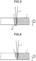
- FIG. 3 and FIG. 4 each schematically illustrate a cross section of the laser beam welded portion 5.
- the laser beam welded portion 5 When the laser beam welded portion 5 is irradiated with the laser beam from outside the welded pipe, the steel material is melted by energy of the laser beam, and while forming a keyhole, the laser beam penetrates therethrough.
- a spatter jetted portion
- a spatter SP is also radially spattered to a laser beam welding penetration side inside the welded pipe.
- This spatter SP is generated, as illustrated in FIG. 3 , in penetrated welding, and is not generated, as illustrated in FIG. 4 , upon a welding defect not resulting in penetrated welding. Therefore, presence of the spatter SP is able to be used as direct evidence that the laser beam welding has resulted in penetrated welding and has gone well.
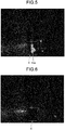
- FIG. 5 is an example of an image in a case where a spatter SP has been generated, and a bright image area Esp of the spatter SP is able to be confirmed in the predetermined area E around the laser beam welded portion 5.
- FIG. 6 is an example of an image in a case where a spatter SP is not generated, and the bright image area Esp of the spatter SP is unable to be confirmed in the predetermined area E.
- a position at which the spatter SP is generated is substantially constant. If the bright image area Esp of a spatter SP is present in an area outside the predetermined area E, the laser beam is emitted diagonally to an end face of the butted portion 9, the laser beam irradiation point is displaced from the laser beam welded portion 5, or the like. Therefore, any case where the spatter SP is not present in the predetermined area E is able to be determined as a welding defect.
- an area (number of pixels) of a bright portion in the predetermined area E is calculated as the spatter feature amount C by the feature amount calculating unit 11.
- the welding diagnosis unit 12 determines that a spatter SP has not been generated and the welding has resulted in failure, if this spatter feature amount C becomes equal to or less than a predetermined value Cth for a predetermined duration or longer.
- This predetermined duration may be an integer multiple of an imaging interval at which the imaging unit 8 continuously captures the images.
- This predetermined duration may be a single imaging interval.
- FIG. 7 illustrates an example of change in spatter feature amount C versus welding length.
- the image in FIG. 5 is that of a position P1 on the graph and the image in FIG. 6 is that of a position P2 on the graph.
- the welding has resulted in failure without resulting in penetrated welding. Therefore, at a position P3 on the graph when the welding length is 1 m, it is able to be determined that a welding defect has occurred.
- the welding diagnosis unit 12 sets a variable N to an initial value, 0 (Step S101). Thereafter, the feature amount calculating unit 11 obtains an image captured by the imaging unit 8 (Step S102). Further, the feature amount calculating unit 11 performs binalization of an image in the predetermined area E in the obtained image (Step S103). By this binarization, when the pixel values are 0 to 255, the pixel values are separated into 0 (dark) and 255 (bright). Thereafter, by use of this binarized image, an integrated value of pixels having the pixel value of 255 in the predetermined area E is calculated as the spatter feature amount C (Step S104).
- the welding diagnosis unit 12 determines whether or not the spatter feature amount C is equal to or less than the predetermined value Cth (Step S105). If the spatter feature amount C is not equal to or less than the predetermined value Cth (Step S105: No), the process is advanced to Step S101, and the variable N is set to the initial value, 0. On the contrary, if the spatter feature amount C is equal to or less than the predetermined value Cth (Step S105: Yes), the variable N is incremented (Step S106), and whether of not the variable N is equal to or greater than 2 is determined further (Step S107). If the variable N is not equal to or greater than 2 (Step S107: No), the process is advanced to Step S102.
- Step S107 Yes
- an alarm is output via an alarm unit, such as a buzzer, not illustrated (Step S108).
- a light source 14 which irradiates the laser beam welding penetration side of the laser beam welded portion 5 with light of a wavelength equal to or greater than 800 nm and equal to or less than 900 nm, is provided on the cutting bar 3, and a bandpass filter 15, which transmits only light of a wavelength equal to or greater than 800 nm and equal to or less than 900 nm, is provided in an optical receiving unit of the imaging unit 8.
- FIG. 10 illustrates a wavelength spectrum of optical intensity emitted by a spatter SP and the spatter SP includes many wavelength components of less than 800 nm.
- Imaging sensitivity of the imaging unit 8 such as a CCD camera, becomes small in an infrared region exceeding 900 nm. Therefore, by imaging in a wavelength region ⁇ equal to or greater than 800 nm, which is a wavelength region where the spatter optical intensity is small, and equal to or less than 900 nm, where there is imaging sensitivity of the imaging unit 8, an image including both the spatter SP and a steel sheet surface or the like other than the spatter SP is able to be obtained.
- the light source 14 may be a single wavelength light source, or may be a white light source and irradiation wavelength thereof may be limited via a bandpass filter.
- the light source 14 is preferably a semiconductor laser light source (LD) because the semiconductor laser light source is small sized and is able to output high optical intensity.
- LD semiconductor laser light source
- an interference filter of the film dielectric method may be used as the bandpass filter 15, for example.
Landscapes
- Engineering & Computer Science (AREA)
- Physics & Mathematics (AREA)
- Optics & Photonics (AREA)
- Mechanical Engineering (AREA)
- Plasma & Fusion (AREA)
- Quality & Reliability (AREA)
- Computer Vision & Pattern Recognition (AREA)
- General Physics & Mathematics (AREA)
- Theoretical Computer Science (AREA)
- Laser Beam Processing (AREA)
Claims (8)
- Laserstrahlschweißnahtdiagnoseeinrichtung, die Diagnose eines laserstrahlgeschweißten Abschnitts eines geschweißten Rohrs ausführt, das durch Anstoßen beider Kanten eines Stahlstreifens gegeneinander und Bestrahlen eines angestoßenen Abschnitts mit einem Laserstrahl geschweißt ist, wobei die Laserstrahlschweißnahtdiagnoseeinrichtung umfasst:eine Bildgebungseinheit (8), die konfiguriert ist, um kontinuierlich Bilder einer Laserstrahlschweißnahtdurchdringseite des laserstrahlgeschweißten Abschnitts (5) aufzunehmen; undeine Merkmalmengenberechnungseinheit (11), die konfiguriert ist, um aus einem Bild, das von der Bildgebungseinheit (8) aufgenommen wird, eine Merkmalmenge von Spritzern (SP), die das Laserstrahlschweißnahtdurchdringen begleiten, zu berechnen;dadurch gekennzeichnet, dass die Laserstrahlschweißnahtdiagnoseeinrichtung weiter umfasst:eine Schweißnahtdiagnoseeinheit (12), die konfiguriert ist, um zu bestimmen, dass ein Schweißnahtfehler, der nicht in eingedrungenem Schweißen in dem laserstrahlgeschweißten Abschnitt (5) resultiert, aufgetreten ist, wenn Werte der Merkmalmengen einer vorbestimmten Fläche, die dem laserstrahlgeschweißten Abschnitt (5) auf den erhaltenen Bildern entspricht, während einer vorbestimmten Dauer oder länger gleich oder kleiner werden als ein vorbestimmter Wert; undeine Ausgabeeinheit, die konfiguriert ist, um einen Schweißqualitätszustand, der das Auftreten des Schweißnahtfehlers beinhaltet, auszugeben.
- Laserstrahlschweißnahtdiagnoseeinrichtung nach Anspruch 1, wobei die Merkmalmenge eine Fläche ist, die von den Spritzern (SP) in der vorbestimmten Fläche belegt ist.
- Laserstrahlschweißnahtdiagnoseeinrichtung nach Anspruch 1 oder 2, wobei die Bildgebungseinheit (8) Licht mit einer Wellenlänge, das von den Spritzern (SP) abgegeben wird, erfasst.
- Laserstrahlschweißnahtdiagnoseeinrichtung nach Anspruch 1 oder 2, umfassend:eine Lichtquelle (4), die konfiguriert ist, um die Laserstrahlschweißnahtdurchdringseite des laserstrahlgeschweißten Abschnitts (5) mit Licht mit einer Wellenlänge gleich oder größer als 800 nm und gleich oder kleiner als 900 nm zu bestrahlen; undein Bandpassfilter, das in einer Lichtempfangseinheit der Bildgebungseinheit (8) bereitgestellt und konfiguriert ist, um nur das Licht mit der Wellenlänge gleich oder größer als 800 nm und gleich oder kleiner als 900 nm zu übertragen, wobeidie Bildgebungseinheit (8) die Bilder der Laserstrahlschweißnahtdurchdringseite des laserstrahlgeschweißten Abschnitts (5) kontinuierlich aufnimmt, indem das Licht mit der Wellenlänge gleich oder größer als 800 nm und gleich oder kleiner als 900 nm empfangen wird.
- Laserstrahlschweißnahtdiagnoseverfahren zum Ausführen einer Diagnose eines laserstrahlgeschweißten Abschnitts (5) eines geschweißten Rohrs, das durch Anstoßen beider Kanten eines Stahlstreifens gegeneinander und Bestrahlen eines angestoßenen Abschnitts (9) mit einem Laserstrahl (7) geschweißt ist, wobei das Laserstrahlschweißnahtdiagnoseverfahren umfasst:einen Bildgebungsschritt des kontinuierlichen Aufnehmens von Bildern einer Laserstrahlschweißnahtdurchdringseite des laserstrahlgeschweißten Abschnitts (5); undeinen Merkmalmengenberechnungsschritt des Berechnens aus einem Bild, das bei dem Bildgebungsschritt aufgenommen wird, einer Merkmalmenge von Spritzern (SP), die Laserstrahlschweißnahtdurchdringen begleiten;einen Schweißdiagnoseschritt des Bestimmens, dass ein Schweißnahtfehler, der nicht in durchdringendem Schweißen in dem laserstrahlgeschweißten Abschnitt (5) resultiert, aufgetreten ist, wenn Werte der Merkmalmengen einer vorbestimmten Fläche, die dem laserstrahlgeschweißten Abschnitt (5) auf den erhaltenen Bildern entspricht, für eine vorbestimmte Dauer oder länger gleich oder kleiner werden als ein vorbestimmter Wert; undeinen Ausgabeschritt des Ausgebens eines Schweißqualitätszustands, der das Auftreten des Schweißnahtfehlers beinhaltet.
- Laserstrahlschweißnahtdiagnoseverfahren nach Anspruch 5, wobei die Merkmalmenge eine Fläche ist, die von den Spritzern (SP) in der vorbestimmten Fläche belegt ist.
- Laserstrahlschweißnahtdiagnoseverfahren nach Anspruch 5 oder 6, wobei bei dem Bildgebungsschritt Licht mit einer Wellenlänge, das von den Spritzern (SP) abgegeben wird, erfasst wird.
- Laserstrahlschweißnahtdiagnoseverfahren nach Anspruch 5 oder 6, umfassend:einen Bestrahlungsschritt mit einer einzigen Wellenlänge des Bestrahlens der Laserstrahlschweißnahtdurchdringseite des laserstrahlgeschweißten Abschnitts (5) mit Licht mit einer Wellenlänge gleich oder größer als 800 nm und gleich oder kleiner als 900 nm, wobeibei dem Bildgebungsschritt die Bilder der Laserstrahlschweißnahtdurchdringseite des laserstrahlgeschweißten Abschnitts (5) kontinuierlich durch Empfangen nur des Lichts mit der Wellenlänge gleich oder größer als 800 nm und gleich oder kleiner als 900 nm kontinuierlich aufgenommen werden.
Applications Claiming Priority (2)
| Application Number | Priority Date | Filing Date | Title |
|---|---|---|---|
| JP2013189594A JP5967042B2 (ja) | 2013-09-12 | 2013-09-12 | レーザ溶接良否判定装置及びレーザ溶接良否判定方法 |
| PCT/JP2014/072747 WO2015037457A1 (ja) | 2013-09-12 | 2014-08-29 | レーザ溶接良否判定装置及びレーザ溶接良否判定方法 |
Publications (3)
| Publication Number | Publication Date |
|---|---|
| EP3045255A1 EP3045255A1 (de) | 2016-07-20 |
| EP3045255A4 EP3045255A4 (de) | 2017-05-17 |
| EP3045255B1 true EP3045255B1 (de) | 2021-08-04 |
Family
ID=52665571
Family Applications (1)
| Application Number | Title | Priority Date | Filing Date |
|---|---|---|---|
| EP14843489.7A Active EP3045255B1 (de) | 2013-09-12 | 2014-08-29 | Vorrichtung und verfahren zur bestimmung einer laserschweissqualität |
Country Status (6)
| Country | Link |
|---|---|
| US (1) | US10002418B2 (de) |
| EP (1) | EP3045255B1 (de) |
| JP (1) | JP5967042B2 (de) |
| KR (1) | KR20160035085A (de) |
| CN (1) | CN105531070B (de) |
| WO (1) | WO2015037457A1 (de) |
Families Citing this family (25)
| Publication number | Priority date | Publication date | Assignee | Title |
|---|---|---|---|---|
| JP2017122264A (ja) * | 2016-01-07 | 2017-07-13 | 新日鐵住金株式会社 | レーザ溝加工モニタリング方法、レーザ溝加工モニタリング装置、レーザ溝加工装置及び方向性磁性鋼板製造装置 |
| JP6159005B1 (ja) * | 2016-11-21 | 2017-07-05 | 株式会社中田製作所 | 溶接管製造装置および溶接管製造方法 |
| JP6677344B2 (ja) * | 2017-03-14 | 2020-04-08 | Jfeスチール株式会社 | 帯状体の蛇行量測定方法および装置並びに帯状体の蛇行異常検出方法および装置 |
| WO2019142350A1 (ja) * | 2018-01-22 | 2019-07-25 | 日本製鉄株式会社 | 溶接操業監視システムおよび溶接操業監視方法 |
| JP6654214B2 (ja) * | 2018-04-20 | 2020-02-26 | 大陽日酸株式会社 | スパッタ計数方法、コンピュータプログラム及びスパッタ計数装置 |
| CN110961821A (zh) * | 2018-09-30 | 2020-04-07 | 宝山钢铁股份有限公司 | 一种实现带钢激光拼接焊缝检查自动判定与放行的方法 |
| JP2020069518A (ja) * | 2018-11-01 | 2020-05-07 | パナソニックIpマネジメント株式会社 | 溶接モニタリング装置および溶接モニタリング方法 |
| JP7262074B2 (ja) * | 2019-02-27 | 2023-04-21 | パナソニックIpマネジメント株式会社 | 円筒型電池の製造装置 |
| JP7357463B2 (ja) * | 2019-05-08 | 2023-10-06 | 株式会社東芝 | 判定装置、判定システム、溶接システム、判定方法、プログラム、及び記憶媒体 |
| DE102019209100A1 (de) * | 2019-06-24 | 2020-12-24 | Robert Bosch Gmbh | Qualitätsüberwachung für einen Laserstrahl-Schweißprozess |
| JP7336893B2 (ja) * | 2019-06-26 | 2023-09-01 | 日立Astemo株式会社 | 溶接システム及び溶接方法 |
| CN110899973A (zh) * | 2019-12-02 | 2020-03-24 | 北京首钢冷轧薄板有限公司 | 一种用于提高焊缝质量的方法及装置 |
| CN111426685B (zh) * | 2020-03-20 | 2022-04-12 | 合肥国轩高科动力能源有限公司 | 一种锂电池激光焊接的检测方法 |
| DE102020205872B4 (de) | 2020-05-11 | 2025-03-06 | TRUMPF Laser- und Systemtechnik SE | Verfahren zum Bestimmen der Schmelzespritzerhäufigkeit und zum Regeln eines Bearbeitungsparameters bei der Laserbearbeitung sowie zugehörige Bearbeitungsmaschine und Computerprogrammprodukt |
| CN115515744B (zh) * | 2020-05-15 | 2025-07-22 | 松下知识产权经营株式会社 | 焊接条件设定辅助装置 |
| DE102020210419A1 (de) | 2020-08-17 | 2022-02-17 | Trumpf Laser- Und Systemtechnik Gmbh | Verfahren zur Prozessüberwachung und zum Regeln eines Bearbeitungsparameters beim Wärmeleitschweißen sowie zugehörige Bearbeitungsmaschine und Computerprogrammprodukt |
| DE102020210974A1 (de) | 2020-08-31 | 2022-03-03 | Ford Global Technologies, Llc | Verfahren und Vorrichtung zum Ermitteln von Defekten während eines Oberflächenmodifizierungsverfahrens |
| JP7792585B2 (ja) * | 2021-02-26 | 2025-12-26 | パナソニックIpマネジメント株式会社 | レーザ加工状態の判定方法及び判定装置 |
| CN113674206B (zh) * | 2021-07-21 | 2022-10-25 | 华南理工大学 | 一种适用于深熔k-tig焊熔池和锁孔入口特征参数的提取方法 |
| DE102021120435A1 (de) | 2021-08-05 | 2023-02-09 | Ford Global Technologies, Llc | Verfahren und Vorrichtung zum Ermitteln der Größe von Defekten während eines Oberflächenmodifizierungsverfahrens |
| CN114523203B (zh) * | 2022-03-13 | 2022-11-29 | 扬州沃盛车业制造有限公司 | 一种激光智能焊接方法及系统 |
| JP7904588B2 (ja) * | 2022-06-28 | 2026-08-13 | 株式会社ナ・デックス | 溶接品質評価装置、及び溶接品質評価プログラム |
| CN115229363B (zh) * | 2022-08-05 | 2023-05-30 | 湖南湘投金天新材料有限公司 | 一种直缝连续焊管内焊缝成形监测装置 |
| JP2024151409A (ja) * | 2023-04-12 | 2024-10-25 | プライムプラネットエナジー&ソリューションズ株式会社 | スパッタ計測システム |
| JP2024151407A (ja) * | 2023-04-12 | 2024-10-25 | プライムプラネットエナジー&ソリューションズ株式会社 | スパッタ計測システム |
Family Cites Families (24)
| Publication number | Priority date | Publication date | Assignee | Title |
|---|---|---|---|---|
| JPS5397949A (en) | 1976-09-08 | 1978-08-26 | Komatsu Mfg Co Ltd | Electron beam or laser beam welding method and its device |
| ZA838150B (en) * | 1982-11-01 | 1984-06-27 | Nat Res Dev | Automatic welding |
| DE3632952A1 (de) | 1986-09-27 | 1988-04-07 | Hoesch Ag | Verfahren und vorrichtung zur kontinuierlichen herstellung rohrfoermiger koerper mittels laser-laengsnahtschweissung |
| DE3908187A1 (de) * | 1989-03-14 | 1990-09-20 | Jurca Marius Christian | Verfahren zur qualitaetssicherung beim laserstrahlschweissen und -schneiden |
| JPH08267241A (ja) * | 1995-03-31 | 1996-10-15 | Kobe Steel Ltd | 溶接時における裏波形成状態の判定方法 |
| DE19527070C1 (de) * | 1995-07-25 | 1996-10-10 | Fraunhofer Ges Forschung | Schweißverfahren mit mehreren Hochenergie-Schweißstrahlen |
| JPH1076383A (ja) * | 1996-08-30 | 1998-03-24 | Nkk Corp | レーザ溶接モニタ方法 |
| JPH1085973A (ja) * | 1996-09-10 | 1998-04-07 | Kinki Kou Energ Kako Gijutsu Kenkyusho | レーザ溶接制御装置 |
| JP4491850B2 (ja) | 1999-03-12 | 2010-06-30 | Jfeスチール株式会社 | レーザ溶接機におけるレーザ照射点検出装置及びシーム位置検出装置 |
| JP3579788B2 (ja) | 1999-07-13 | 2004-10-20 | 株式会社日立製作所 | 裏波溶接制御方法及びその装置 |
| JP2001138082A (ja) | 1999-11-05 | 2001-05-22 | Amada Co Ltd | レーザ切断加工制御方法および装置 |
| FR2811427B1 (fr) * | 2000-07-06 | 2002-10-25 | Aerospatiale Matra Ccr | Procede de detection et d'identification de defauts dans un cordon de soudure realise par faisceau laser |
| DE10120251B4 (de) * | 2001-04-25 | 2006-03-23 | Precitec Kg | Verfahren und Sensorvorrichtung zur Überwachung eines an einem Werkstück durchzuführenden Laserbearbeitungsvorgangs sowie Laserbearbeitungskopf mit einer derartigen Sensorvorrichtung |
| CA2504368C (en) * | 2002-10-31 | 2012-07-10 | Ehsan Toyserkani | System and method for closed-loop control of laser cladding by powder injection |
| DE10338062B4 (de) * | 2003-08-19 | 2005-11-03 | Daimlerchrysler Ag | Verfahren zur Qualitätskontrolle von thermischen Fügeverfahren |
| MXPA06015167A (es) * | 2004-06-30 | 2007-10-23 | Georgetown Rail Equipment Comp | Sistema y metodo para inspeccionar vias de ferrocarril. |
| JP4179558B2 (ja) | 2004-09-17 | 2008-11-12 | トヨタ自動車株式会社 | レーザ溶接品質評価方法および装置 |
| DE102006004919A1 (de) * | 2006-02-01 | 2007-08-16 | Thyssenkrupp Steel Ag | Laserstrahlschweißkopf |
| US20080041827A1 (en) * | 2006-05-26 | 2008-02-21 | Wei Li | Resistance Spot Welding Monitoring System and Method |
| JP4300433B2 (ja) * | 2007-08-10 | 2009-07-22 | トヨタ自動車株式会社 | レーザ溶接品質評価方法及びその装置 |
| JP5200469B2 (ja) | 2007-09-18 | 2013-06-05 | Jfeスチール株式会社 | 溶接のスパーク検出方法及びスパーク検出装置ならびに溶接製品の製造方法 |
| CN102066040B (zh) * | 2008-06-23 | 2015-08-12 | 杰富意钢铁株式会社 | 激光焊接钢管的制造方法 |
| JP5354335B2 (ja) * | 2008-11-12 | 2013-11-27 | スズキ株式会社 | レーザ加工良否判定方法及び装置 |
| DE112010003406B4 (de) | 2009-08-27 | 2021-05-06 | Ihi Inspection & Instrumentation Co., Ltd. | Laserschweißgütebestimmungs-Verfahren und -Vorrichtung |
-
2013
- 2013-09-12 JP JP2013189594A patent/JP5967042B2/ja not_active Expired - Fee Related
-
2014
- 2014-08-29 WO PCT/JP2014/072747 patent/WO2015037457A1/ja not_active Ceased
- 2014-08-29 CN CN201480049953.5A patent/CN105531070B/zh not_active Expired - Fee Related
- 2014-08-29 US US14/917,132 patent/US10002418B2/en not_active Expired - Fee Related
- 2014-08-29 KR KR1020167006043A patent/KR20160035085A/ko not_active Ceased
- 2014-08-29 EP EP14843489.7A patent/EP3045255B1/de active Active
Also Published As
| Publication number | Publication date |
|---|---|
| CN105531070A (zh) | 2016-04-27 |
| KR20160035085A (ko) | 2016-03-30 |
| EP3045255A4 (de) | 2017-05-17 |
| EP3045255A1 (de) | 2016-07-20 |
| WO2015037457A1 (ja) | 2015-03-19 |
| US20160203596A1 (en) | 2016-07-14 |
| US10002418B2 (en) | 2018-06-19 |
| JP5967042B2 (ja) | 2016-08-10 |
| CN105531070B (zh) | 2019-06-07 |
| JP2015054343A (ja) | 2015-03-23 |
Similar Documents
| Publication | Publication Date | Title |
|---|---|---|
| US10002418B2 (en) | Laser beam welding diagnosis apparatus and laser beam welding diagnosis method | |
| JP5338890B2 (ja) | レーザ溶接の溶接位置検出装置および溶接位置検出方法 | |
| Kim et al. | Coaxial monitoring of keyhole during Yb: YAG laser welding | |
| KR102156686B1 (ko) | 레이저 용접에서 고온 균열들의 검출 | |
| JP5354335B2 (ja) | レーザ加工良否判定方法及び装置 | |
| JP6221013B1 (ja) | 溶接監視装置及び溶接監視方法 | |
| CN105142848B (zh) | 具有用于提取蒸发冷光和热辐射的提取部的焊接部检查装置及其检查方法 | |
| US9969028B2 (en) | Welded portion inspection method | |
| JP5375527B2 (ja) | レーザ溶接鋼管の製造方法 | |
| US20120152916A1 (en) | Laser welding quality determination method and apparatus | |
| US20220118548A1 (en) | Method and processing machine for pore defect monitoring of a laser welding process for welding a plurality of bar conductors and associated computer program product | |
| JP2009072788A (ja) | 溶接のスパーク検出方法及びスパーク検出装置ならびに溶接製品の製造方法 | |
| US20080237197A1 (en) | System and method for welding and real time monitoring of seam welded parts | |
| CN111479648B (zh) | 用于监控工件的射束处理的装置、方法及用途 | |
| JP2006082129A (ja) | レーザ溶接品質評価方法および装置 | |
| JP3230447B2 (ja) | 電縫管シーム部検出装置及び方法 | |
| JP2020069518A (ja) | 溶接モニタリング装置および溶接モニタリング方法 | |
| JP2012121067A (ja) | 溶接欠陥検出方法及びシステム及び電縫鋼管の製造方法並びに溶接製品 | |
| JP6094690B2 (ja) | レーザ溶接鋼管のレーザ照射位置ずれ検出方法、鋼管の製造方法、レーザ照射位置ずれ検出装置、鋼管のレーザ溶接装置、および鋼管の製造装置 | |
| JP2007330987A (ja) | 溶接部可視化装置を用いた溶接状況解析装置及び方法 | |
| KR20140084612A (ko) | 주편 에지 모니터링 시스템 및 방법 | |
| RU2456107C1 (ru) | Способ изготовления стальной трубы лазерной сваркой | |
| JP5601015B2 (ja) | 低炭素低合金鋼電縫管の入熱制御システム | |
| Allen et al. | Development of Combined Seam Tracking and Process Monitoring for Laser Welding | |
| JP2008175577A (ja) | 電縫溶接管溶接部監視方法及び監視装置並びに電縫溶接管の製造方法 |
Legal Events
| Date | Code | Title | Description |
|---|---|---|---|
| PUAI | Public reference made under article 153(3) epc to a published international application that has entered the european phase |
Free format text: ORIGINAL CODE: 0009012 |
|
| 17P | Request for examination filed |
Effective date: 20160309 |
|
| AK | Designated contracting states |
Kind code of ref document: A1 Designated state(s): AL AT BE BG CH CY CZ DE DK EE ES FI FR GB GR HR HU IE IS IT LI LT LU LV MC MK MT NL NO PL PT RO RS SE SI SK SM TR |
|
| AX | Request for extension of the european patent |
Extension state: BA ME |
|
| DAX | Request for extension of the european patent (deleted) | ||
| A4 | Supplementary search report drawn up and despatched |
Effective date: 20170421 |
|
| RIC1 | Information provided on ipc code assigned before grant |
Ipc: B23K 103/04 20060101ALI20170413BHEP Ipc: B23K 31/12 20060101ALI20170413BHEP Ipc: B23K 26/06 20140101ALI20170413BHEP Ipc: B23K 26/21 20140101ALI20170413BHEP Ipc: B23K 26/00 20140101AFI20170413BHEP |
|
| GRAP | Despatch of communication of intention to grant a patent |
Free format text: ORIGINAL CODE: EPIDOSNIGR1 |
|
| STAA | Information on the status of an ep patent application or granted ep patent |
Free format text: STATUS: GRANT OF PATENT IS INTENDED |
|
| INTG | Intention to grant announced |
Effective date: 20210414 |
|
| GRAS | Grant fee paid |
Free format text: ORIGINAL CODE: EPIDOSNIGR3 |
|
| GRAA | (expected) grant |
Free format text: ORIGINAL CODE: 0009210 |
|
| STAA | Information on the status of an ep patent application or granted ep patent |
Free format text: STATUS: THE PATENT HAS BEEN GRANTED |
|
| AK | Designated contracting states |
Kind code of ref document: B1 Designated state(s): AL AT BE BG CH CY CZ DE DK EE ES FI FR GB GR HR HU IE IS IT LI LT LU LV MC MK MT NL NO PL PT RO RS SE SI SK SM TR |
|
| REG | Reference to a national code |
Ref country code: GB Ref legal event code: FG4D |
|
| REG | Reference to a national code |
Ref country code: AT Ref legal event code: REF Ref document number: 1416481 Country of ref document: AT Kind code of ref document: T Effective date: 20210815 |
|
| REG | Reference to a national code |
Ref country code: CH Ref legal event code: EP |
|
| REG | Reference to a national code |
Ref country code: DE Ref legal event code: R096 Ref document number: 602014079266 Country of ref document: DE |
|
| REG | Reference to a national code |
Ref country code: IE Ref legal event code: FG4D |
|
| REG | Reference to a national code |
Ref country code: NL Ref legal event code: FP |
|
| REG | Reference to a national code |
Ref country code: LT Ref legal event code: MG9D |
|
| REG | Reference to a national code |
Ref country code: AT Ref legal event code: MK05 Ref document number: 1416481 Country of ref document: AT Kind code of ref document: T Effective date: 20210804 |
|
| PG25 | Lapsed in a contracting state [announced via postgrant information from national office to epo] |
Ref country code: HR Free format text: LAPSE BECAUSE OF FAILURE TO SUBMIT A TRANSLATION OF THE DESCRIPTION OR TO PAY THE FEE WITHIN THE PRESCRIBED TIME-LIMIT Effective date: 20210804 Ref country code: RS Free format text: LAPSE BECAUSE OF FAILURE TO SUBMIT A TRANSLATION OF THE DESCRIPTION OR TO PAY THE FEE WITHIN THE PRESCRIBED TIME-LIMIT Effective date: 20210804 Ref country code: SE Free format text: LAPSE BECAUSE OF FAILURE TO SUBMIT A TRANSLATION OF THE DESCRIPTION OR TO PAY THE FEE WITHIN THE PRESCRIBED TIME-LIMIT Effective date: 20210804 Ref country code: PT Free format text: LAPSE BECAUSE OF FAILURE TO SUBMIT A TRANSLATION OF THE DESCRIPTION OR TO PAY THE FEE WITHIN THE PRESCRIBED TIME-LIMIT Effective date: 20211206 Ref country code: NO Free format text: LAPSE BECAUSE OF FAILURE TO SUBMIT A TRANSLATION OF THE DESCRIPTION OR TO PAY THE FEE WITHIN THE PRESCRIBED TIME-LIMIT Effective date: 20211104 Ref country code: FI Free format text: LAPSE BECAUSE OF FAILURE TO SUBMIT A TRANSLATION OF THE DESCRIPTION OR TO PAY THE FEE WITHIN THE PRESCRIBED TIME-LIMIT Effective date: 20210804 Ref country code: ES Free format text: LAPSE BECAUSE OF FAILURE TO SUBMIT A TRANSLATION OF THE DESCRIPTION OR TO PAY THE FEE WITHIN THE PRESCRIBED TIME-LIMIT Effective date: 20210804 Ref country code: LT Free format text: LAPSE BECAUSE OF FAILURE TO SUBMIT A TRANSLATION OF THE DESCRIPTION OR TO PAY THE FEE WITHIN THE PRESCRIBED TIME-LIMIT Effective date: 20210804 Ref country code: BG Free format text: LAPSE BECAUSE OF FAILURE TO SUBMIT A TRANSLATION OF THE DESCRIPTION OR TO PAY THE FEE WITHIN THE PRESCRIBED TIME-LIMIT Effective date: 20211104 Ref country code: AT Free format text: LAPSE BECAUSE OF FAILURE TO SUBMIT A TRANSLATION OF THE DESCRIPTION OR TO PAY THE FEE WITHIN THE PRESCRIBED TIME-LIMIT Effective date: 20210804 |
|
| PG25 | Lapsed in a contracting state [announced via postgrant information from national office to epo] |
Ref country code: PL Free format text: LAPSE BECAUSE OF FAILURE TO SUBMIT A TRANSLATION OF THE DESCRIPTION OR TO PAY THE FEE WITHIN THE PRESCRIBED TIME-LIMIT Effective date: 20210804 Ref country code: LV Free format text: LAPSE BECAUSE OF FAILURE TO SUBMIT A TRANSLATION OF THE DESCRIPTION OR TO PAY THE FEE WITHIN THE PRESCRIBED TIME-LIMIT Effective date: 20210804 Ref country code: GR Free format text: LAPSE BECAUSE OF FAILURE TO SUBMIT A TRANSLATION OF THE DESCRIPTION OR TO PAY THE FEE WITHIN THE PRESCRIBED TIME-LIMIT Effective date: 20211105 |
|
| REG | Reference to a national code |
Ref country code: CH Ref legal event code: PL |
|
| REG | Reference to a national code |
Ref country code: BE Ref legal event code: MM Effective date: 20210831 |
|
| PG25 | Lapsed in a contracting state [announced via postgrant information from national office to epo] |
Ref country code: DK Free format text: LAPSE BECAUSE OF FAILURE TO SUBMIT A TRANSLATION OF THE DESCRIPTION OR TO PAY THE FEE WITHIN THE PRESCRIBED TIME-LIMIT Effective date: 20210804 Ref country code: CH Free format text: LAPSE BECAUSE OF NON-PAYMENT OF DUE FEES Effective date: 20210831 Ref country code: LI Free format text: LAPSE BECAUSE OF NON-PAYMENT OF DUE FEES Effective date: 20210831 |
|
| REG | Reference to a national code |
Ref country code: DE Ref legal event code: R097 Ref document number: 602014079266 Country of ref document: DE |
|
| PG25 | Lapsed in a contracting state [announced via postgrant information from national office to epo] |
Ref country code: SM Free format text: LAPSE BECAUSE OF FAILURE TO SUBMIT A TRANSLATION OF THE DESCRIPTION OR TO PAY THE FEE WITHIN THE PRESCRIBED TIME-LIMIT Effective date: 20210804 Ref country code: SK Free format text: LAPSE BECAUSE OF FAILURE TO SUBMIT A TRANSLATION OF THE DESCRIPTION OR TO PAY THE FEE WITHIN THE PRESCRIBED TIME-LIMIT Effective date: 20210804 Ref country code: RO Free format text: LAPSE BECAUSE OF FAILURE TO SUBMIT A TRANSLATION OF THE DESCRIPTION OR TO PAY THE FEE WITHIN THE PRESCRIBED TIME-LIMIT Effective date: 20210804 Ref country code: MC Free format text: LAPSE BECAUSE OF FAILURE TO SUBMIT A TRANSLATION OF THE DESCRIPTION OR TO PAY THE FEE WITHIN THE PRESCRIBED TIME-LIMIT Effective date: 20210804 Ref country code: LU Free format text: LAPSE BECAUSE OF NON-PAYMENT OF DUE FEES Effective date: 20210829 Ref country code: EE Free format text: LAPSE BECAUSE OF FAILURE TO SUBMIT A TRANSLATION OF THE DESCRIPTION OR TO PAY THE FEE WITHIN THE PRESCRIBED TIME-LIMIT Effective date: 20210804 Ref country code: CZ Free format text: LAPSE BECAUSE OF FAILURE TO SUBMIT A TRANSLATION OF THE DESCRIPTION OR TO PAY THE FEE WITHIN THE PRESCRIBED TIME-LIMIT Effective date: 20210804 Ref country code: AL Free format text: LAPSE BECAUSE OF FAILURE TO SUBMIT A TRANSLATION OF THE DESCRIPTION OR TO PAY THE FEE WITHIN THE PRESCRIBED TIME-LIMIT Effective date: 20210804 |
|
| PLBE | No opposition filed within time limit |
Free format text: ORIGINAL CODE: 0009261 |
|
| STAA | Information on the status of an ep patent application or granted ep patent |
Free format text: STATUS: NO OPPOSITION FILED WITHIN TIME LIMIT |
|
| 26N | No opposition filed |
Effective date: 20220506 |
|
| GBPC | Gb: european patent ceased through non-payment of renewal fee |
Effective date: 20211104 |
|
| PG25 | Lapsed in a contracting state [announced via postgrant information from national office to epo] |
Ref country code: IE Free format text: LAPSE BECAUSE OF NON-PAYMENT OF DUE FEES Effective date: 20210829 Ref country code: BE Free format text: LAPSE BECAUSE OF NON-PAYMENT OF DUE FEES Effective date: 20210831 |
|
| PG25 | Lapsed in a contracting state [announced via postgrant information from national office to epo] |
Ref country code: SI Free format text: LAPSE BECAUSE OF FAILURE TO SUBMIT A TRANSLATION OF THE DESCRIPTION OR TO PAY THE FEE WITHIN THE PRESCRIBED TIME-LIMIT Effective date: 20210804 |
|
| PG25 | Lapsed in a contracting state [announced via postgrant information from national office to epo] |
Ref country code: FR Free format text: LAPSE BECAUSE OF NON-PAYMENT OF DUE FEES Effective date: 20211004 |
|
| PG25 | Lapsed in a contracting state [announced via postgrant information from national office to epo] |
Ref country code: GB Free format text: LAPSE BECAUSE OF NON-PAYMENT OF DUE FEES Effective date: 20211104 |
|
| PG25 | Lapsed in a contracting state [announced via postgrant information from national office to epo] |
Ref country code: HU Free format text: LAPSE BECAUSE OF FAILURE TO SUBMIT A TRANSLATION OF THE DESCRIPTION OR TO PAY THE FEE WITHIN THE PRESCRIBED TIME-LIMIT; INVALID AB INITIO Effective date: 20140829 |
|
| PG25 | Lapsed in a contracting state [announced via postgrant information from national office to epo] |
Ref country code: CY Free format text: LAPSE BECAUSE OF FAILURE TO SUBMIT A TRANSLATION OF THE DESCRIPTION OR TO PAY THE FEE WITHIN THE PRESCRIBED TIME-LIMIT Effective date: 20210804 |
|
| PGFP | Annual fee paid to national office [announced via postgrant information from national office to epo] |
Ref country code: NL Payment date: 20230718 Year of fee payment: 10 |
|
| PGFP | Annual fee paid to national office [announced via postgrant information from national office to epo] |
Ref country code: TR Payment date: 20230828 Year of fee payment: 10 Ref country code: IT Payment date: 20230711 Year of fee payment: 10 |
|
| PGFP | Annual fee paid to national office [announced via postgrant information from national office to epo] |
Ref country code: DE Payment date: 20230705 Year of fee payment: 10 |
|
| PG25 | Lapsed in a contracting state [announced via postgrant information from national office to epo] |
Ref country code: MK Free format text: LAPSE BECAUSE OF FAILURE TO SUBMIT A TRANSLATION OF THE DESCRIPTION OR TO PAY THE FEE WITHIN THE PRESCRIBED TIME-LIMIT Effective date: 20210804 |
|
| PG25 | Lapsed in a contracting state [announced via postgrant information from national office to epo] |
Ref country code: MT Free format text: LAPSE BECAUSE OF FAILURE TO SUBMIT A TRANSLATION OF THE DESCRIPTION OR TO PAY THE FEE WITHIN THE PRESCRIBED TIME-LIMIT Effective date: 20210804 |
|
| REG | Reference to a national code |
Ref country code: DE Ref legal event code: R119 Ref document number: 602014079266 Country of ref document: DE |
|
| REG | Reference to a national code |
Ref country code: NL Ref legal event code: MM Effective date: 20240901 |
|
| PG25 | Lapsed in a contracting state [announced via postgrant information from national office to epo] |
Ref country code: NL Free format text: LAPSE BECAUSE OF NON-PAYMENT OF DUE FEES Effective date: 20240901 |
|
| PG25 | Lapsed in a contracting state [announced via postgrant information from national office to epo] |
Ref country code: DE Free format text: LAPSE BECAUSE OF NON-PAYMENT OF DUE FEES Effective date: 20250301 |
|
| PG25 | Lapsed in a contracting state [announced via postgrant information from national office to epo] |
Ref country code: IT Free format text: LAPSE BECAUSE OF NON-PAYMENT OF DUE FEES Effective date: 20240829 |
|
| PG25 | Lapsed in a contracting state [announced via postgrant information from national office to epo] |
Ref country code: TR Free format text: LAPSE BECAUSE OF NON-PAYMENT OF DUE FEES Effective date: 20240829 |