EP3045244A1 - Cutting tool - Google Patents
Cutting tool Download PDFInfo
- Publication number
- EP3045244A1 EP3045244A1 EP14843414.5A EP14843414A EP3045244A1 EP 3045244 A1 EP3045244 A1 EP 3045244A1 EP 14843414 A EP14843414 A EP 14843414A EP 3045244 A1 EP3045244 A1 EP 3045244A1
- Authority
- EP
- European Patent Office
- Prior art keywords
- tube
- main body
- wall
- shaped portion
- fluid chamber
- Prior art date
- Legal status (The legal status is an assumption and is not a legal conclusion. Google has not performed a legal analysis and makes no representation as to the accuracy of the status listed.)
- Withdrawn
Links
Images

Classifications
-
- B—PERFORMING OPERATIONS; TRANSPORTING
- B23—MACHINE TOOLS; METAL-WORKING NOT OTHERWISE PROVIDED FOR
- B23B—TURNING; BORING
- B23B31/00—Chucks; Expansion mandrels; Adaptations thereof for remote control
- B23B31/02—Chucks
- B23B31/24—Chucks characterised by features relating primarily to remote control of the gripping means
- B23B31/30—Chucks characterised by features relating primarily to remote control of the gripping means using fluid-pressure means in the chuck
- B23B31/305—Chucks characterised by features relating primarily to remote control of the gripping means using fluid-pressure means in the chuck the gripping means is a deformable sleeve
-
- B—PERFORMING OPERATIONS; TRANSPORTING
- B23—MACHINE TOOLS; METAL-WORKING NOT OTHERWISE PROVIDED FOR
- B23B—TURNING; BORING
- B23B31/00—Chucks; Expansion mandrels; Adaptations thereof for remote control
- B23B31/40—Expansion mandrels
-
- B—PERFORMING OPERATIONS; TRANSPORTING
- B23—MACHINE TOOLS; METAL-WORKING NOT OTHERWISE PROVIDED FOR
- B23B—TURNING; BORING
- B23B51/00—Tools for drilling machines
- B23B51/10—Bits for countersinking
- B23B51/107—Bits for countersinking having a pilot
-
- B—PERFORMING OPERATIONS; TRANSPORTING
- B23—MACHINE TOOLS; METAL-WORKING NOT OTHERWISE PROVIDED FOR
- B23C—MILLING
- B23C3/00—Milling particular work; Special milling operations; Machines therefor
- B23C3/02—Milling surfaces of revolution
- B23C3/05—Finishing valves or valve seats
- B23C3/051—Reconditioning of valve seats
- B23C3/053—Reconditioning of valve seats having means for guiding the tool carrying spindle
- B23C3/055—Reconditioning of valve seats having means for guiding the tool carrying spindle for engines
-
- B—PERFORMING OPERATIONS; TRANSPORTING
- B23—MACHINE TOOLS; METAL-WORKING NOT OTHERWISE PROVIDED FOR
- B23B—TURNING; BORING
- B23B2231/00—Details of chucks, toolholder shanks or tool shanks
- B23B2231/24—Cooling or lubrication means
Definitions
- the present invention relates to a cutting tool which forms a machined hole by cutting an inner wall surface of a prepared hole provided on a work material, for example, in advance, and coaxially cuts an opening portion peripheral edge of the machined hole with respect to the machined hole.
- a cutting tool which performs hole machining of a work material by a reamer (hole machining tool core) protruding in a direction of an axial line of a tool main body, and cuts an opening portion of the machined hole of the work material by a cutting edge provided on an outer circumference of a distal end portion of the tool main body.
- a so-called valve finisher which is an example of the cutting tool, finishing of a stem guide hole and machining of a valve seat in a cylinder head of a four-cycle engine are coaxially performed by the same cutting process.
- Patent Document 1 discloses a cutting tool which includes a tool main body which is capable of being rotated around an axial line and in which a mounting hole is formed in a distal end portion of the tool main body in an axial direction, a reamer which has a shaft shape, is detachably fitted to the inside of the mounting hole, and extends so as to protrude forward from the distal end portion of the tool main body, and a plurality of cutting edges which are circumferentially provided on the outer circumference of the distal end portion of the tool main body with intervals therebetween.
- a collet chuck capable of holding the reamer is provided on the proximal end portion of the tool main body with respect to the mounting hole, and the collet chuck can be made to hold or release the reamer due to operation of a working tool to be inserted from the proximal end portion of the tool main body in a state where the tool main body is removed from a main shaft of the machine tool.
- Patent Document 1 three adjustment screw holes, which extend in a radial direction and in which the inner portions in the radial direction of a hole communicate with the mounting hole, are circumferentially provided on the distal end portion of the tool main body with equal intervals therebetween, the outer circumferential surface of the reamer in the mounting hole is pressed in three directions different from each other inward in the radial direction by a screw distal surface (pressing surface) of an adjustment screw by screwing adjustment screws (adjustment means) to each of the adjustment screw holes, and the axial alignment of the reamer can be performed.
- Patent Document 2 discloses a hydro-chuck in which a fluid chamber is provided inside a chuck tube of a chuck main body, a thin portion is formed on an inner circumferential surface of a tube hole of the chuck tube, a fluid is sealed into the fluid pressure chamber, and an object to be held which is fitted to the tube hole of the chuck tube is held by increasing the pressure inside the fluid pressure chamber and expanding the thin portion.
- the hydro-chuck is used in the cutting tool, preferably, it is possible to increase the accuracy of the axial alignment of the reamer, and it is possible to easily perform attachment and detachment of the reamer.
- the present invention is made in consideration of the above-described circumstances, and an object thereof is to provide a cutting tool capable of detachably mounting a hole machining tool core on a tool main body using a hydro-chuck structure, and sufficiently securing tool rigidity while increasing attachment and detachment operability and accuracy in axial alignment.
- a cutting tool including:
- the tube-shaped portion is provided on the distal end portion of the tool main body, and by increasing the pressure of liquid (fluid) filled inside the fluid chamber formed in the circumferential wall of the tube-shaped portion in the state where the hole machining tool core is fitted to the inside of the tube-shaped portion and the head portion is fitted to the outside the tube-shaped portion, the inner wall portion of the circumferential wall positioned inside the fluid chamber formed in the circumferential wall and the outer wall portion of the circumferential wall positioned outside the fluid chamber of the circumferential wall are elastically deformed in the radial direction of the circumferential wall, and thereby the tube-shaped portion, the hole machining tool core, and the head portion are fixed to each other while being coaxially aligned with each other on the axial line of the tool main body.
- the inner wall portion of the circumferential wall of the tube-shaped portion positioned inside the fluid chamber formed in the circumferential wall is deformed so as to be expanded inward in the radial direction of the circumferential wall, and the inner circumferential surface of the inner wall portion is pressed to the outer circumferential surface of the hole machining tool core. Accordingly, the hole machining tool core is adjusted such that the center axis of the hole machining tool core is accurately coincident with the axial line of the tool main body.
- the outer wall portion of the circumferential wall of the tube-shaped portion positioned outside the fluid chamber formed in the circumferential wall is deformed so as to be expanded outward the tube-shaped portion, and the outer circumferential surface of the outer wall portion is pressed to the inner circumferential surface of the head portion. Accordingly, in a case of a division type of separation in which the head portion and the tool main body are separated from each other (that is, the head portion and the tool main body are movable relatively to each other), the head portion is adjusted such that the center axis of the head portion is accurately coincident with the axial line of the tool main body.
- the tube-shaped portion may be deformed (the diameter thereof may be increased) outward in the radial direction by a reaction force by which the inner wall portion presses the hole machining tool core, or a holding force with respect to the hole machining tool core may not be sufficiently secured.
- the inner wall portion positioned inside in the radial direction of the circumferential wall of the tube-shaped portion is elastically deformed inward in the radial direction
- the outer wall portion positioned outside in the radial direction of the circumferential wall is elastically deformed outward in the radial direction
- the hole machining tool core and the head portion are pressed to each other, and effects in which the reaction forces cancel out each other are obtained. Accordingly, it is possible to effectively prevent the deformation of the tube-shaped portion, and it is possible to sufficiently secure tool rigidity by securing the holding force with respect to the hole machining tool core.
- the axial alignment and the fixation among the tube-shaped portion, the hole machining tool core, and the head portion are performed by a simple operation such as increasing the pressure of the fluid in the fluid chamber, workability is improved. That is, for example, in the related art, when the hole machining tool core or the head portion is attached to the tube-shaped portion of the tool main body, an adjustment screw for fixing the position of the hole machining tool core or the head portion while aligning the hole machining tool core or the head portion in the axial direction, or the like is necessary.
- the adjustment screw is not required, and workability with respect to the axial alignment and the fixation of the reamer is remarkably improved.
- setting of the cutting tool is effectively performed in a short time, man-hours decrease, the workability increases, cutting is performed with high efficiency, and productivity is improved.
- the hole machining tool core and the head portion may be removed from the tube-shaped portion of the tool main body by decreasing the pressure of the fluid filled inside the fluid chamber. Accordingly, the inner wall portion and the outer wall portion which have been elastically deformed as described above are deformed so as to be restored, and it is possible to simply remove the hole machining tool core and the head portion from the tube-shaped portion.
- the tube-shaped portion is provided on the distal end portion of the tool main body, and the hole machining tool core is fitted to the inside of the tube-shaped portion and the head portion is fitted to the outside of the tube-shaped portion, the above-described excellent effects are obtained.
- the hole machining tool core is detachably mounted on the tool main body using the hydro-chuck structure, and it is possible to sufficiently secure the tool rigidity while increasing the attachment and detachment operability and accuracy of the axial alignment.
- the head portion may be detachably mounted on a distal end portion of the tool main body.
- the tool main body and the head portion can be divided into separate units while the rigidity of the distal end portion of the tool main body is sufficiently secured, and thereby the following effects are obtained. That is, for example, a plurality of head portions in which the shapes of the cutting edges or diameters of rotation paths of the cutting edges around the axial line are different from each other can be prepared, and according to the shapes of the opening portions (shapes of the valve seats, diameters of the valve seats, or the like) of various machined holes, or a kind of machining (rough machining, finishing, or the like), the head portion can be selectively exchanged with respect to one set of the tool main body (and the hole machining tool core). Accordingly, it is possible to easily cope with small quantities of various different types of production while decreasing cost of facilities, and when the head portion or the cutting edge is damaged, it is possible to cope with the damage by replacing the head portion, and it is possible to reduce costs.
- the fluid chamber may include an annular fluid chamber portion which is formed in the tube-shaped portion so as to be annularly arranged in a circumferential direction of the tube-shaped portion.
- a plurality of the annular fluid chamber portions may be formed in the tube-shaped portion so as to be positioned at intervals each other in the direction of the axial line.
- the above-described effects obtained by provision of the annular fluid chamber portions to the fluid chamber are obtained at a plurality of locations with intervals therebetween in the axial direction in the tube-shaped portion, and preferably, reliability increases.
- the inner wall portion may be detachably fitted inside the outer wall portion, a seal groove may be formed in the inner wall portion so as to be close to a distal end of the inner wall portion with respect to the fluid chamber, and a seal member may be disposed inside the seal groove.
- a hole machining tool core is detachably mounted on a tool main body using a hydro-chuck structure, and it is possible to sufficiently secure tool rigidity while increasing an attachment and detachment operability and accuracy of axial alignment.
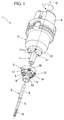
- the cutting tool 1 of the present embodiment is used to perform hole machining of a work material using a reamer (hole machining tool core) 3 protruding in a direction of an axial line O of the tool main body 2, and to cut an opening portion of the machined hole of the work material using a plurality of cutting edges 4 which are provided on an outer circumference of a distal portion of a head portion 9.
- a so-called valve finisher which is an example of the cutting tool, finishing of a stem guide hole and machining of a valve seat in a cylinder head of a four-cycle engine are coaxially performed by the same cutting process.
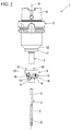
- the cutting tool 1 includes the reamer 3 which is a shaft-shaped hole machining tool core protruding in a direction of a center axis C, the tool main body 2 which is capable of being rotated around the axial line O, and the head portion 9 which has a tube shape and is detachably fitted to the distal end portion of the tool main body 2 and in which the plurality of the cutting edges 4 are provided on the circumferential portion of the head portion 9.
- the reamer 3 is formed of a hard material such as sintered hard alloy and has an elongated columnar shape extending in a direction of the center axis C.
- a cutting edge portion 5 is formed on the distal end portion of the reamer 3, and a shank portion 6 is formed on the proximal side of the reamer with respect to the cutting edge portion 5.
- an outer diameter of the shank portion 6 is larger than an outer diameter of the cutting edge portion 5.
- the reamer 5 is used to cut an inner wall portion surface of a prepared hole provided in the work material in advance using the cutting edge portion 5 so as to form a machined hole having a predetermined inner diameter.
- the tool main body 2 is formed of steel or the like and is formed in a multi-step columnar shape extending in a direction of the axial line O.
- the tool main body 2 has the largest diameter at the center portion in the direction of the axial line O.
- a tube-shaped portion 7 having the smallest outer diameter in the tool main body 2 is provided on the distal end portion (the lower sides in FIGS. 1 and 2 ) of the tool main body 2, and the tube-shaped portion 7 is formed coaxially with the axial line O and extends in the direction of the axial line O.
- a detailed configuration of the tube-shaped portion 7 will be described below.
- An attachment portion 8 for attaching the tool main body 2 to a main spindle of a machine tool such as a machining center (not shown) is provided on the proximal end portion (the upper sides in FIGS. 1 and 2 ) of the tool main body 2 in the direction of the axial line O.
- the proximal end portion (attachment portion 8) of the tool main body 2 is attached to the main spindle of the machine tool, and the cutting tool 1 is fed in the direction of the axial line O while being rotated around the axial line O in a tool rotation direction T so as to cut the work material.
- the tube-shaped portion 7 side of the tool main body 2 in the direction of the axial line O is referred to as a distal side
- the attachment portion 8 side in the direction of the axial line O is referred to as a proximal side.
- a direction orthogonal to the axial line O is referred to a radial direction
- a direction revolving around the direction of the axial line O is referred to as a circumferential direction.
- the direction in which the tool main body 2 is rotated during cutting is referred to as the front side in the tool rotation direction T (or simply referred to as tool rotation direction T), and a direction opposite to the front side in the tool rotation direction T is referred to as the rear side in the tool rotation direction T.
- a coolant supply hole is formed inside the tool main body 2, and a distal end portion of the coolant supply hole opens to the distal surface of the head attachment portion 11 of the tool main body 2.
- the head attachment portion 11 is formed of a portion which is connected to the proximal side of the tube-shaped portion 7 in the tool main body 2, and has a larger diameter than that of the tube-shaped portion 7.
- the outer diameter of the head attachment portion 11 is the same as the outer diameter of the proximal end proximal end portion (maximum diameter portion) of the head portion 9.
- a taper portion 12 in which the diameter gradually increases toward the proximal side is formed on the portion connected to the proximal side of the head attachment portion 11 in the tool main body 2.
- the diameter of the outer circumference surface of the head portion 9 gradually decreases from the proximal end portion of the head portion toward the distal end portion thereof such that the proximal end portion has the largest diameter.
- a plurality of notch portions 13, which are recessed so as to open outward in the radial direction and the distal side of the tool main body 2 are formed on an intermediate portion positioned between the distal portion and the proximal end portion of the head portion 9 with intervals in the circumferential direction, and an insert attachment seat, on which a cutting insert 14 having the cutting edge 4 is detachably mounted, is provided on each of the portions positioned the rear sides in the tool rotation direction T in the notch portions 13.
- one to three notch portions 13 and one to three insert attachment seats are formed with intervals therebetween in the circumferential direction of the head portion 9, and angles between the cutting edges 4 of the cutting inserts 14 mounted on the insert attachment seats and the axial line O are set so as to be different from each other.
- the cutting insert 14 is formed of a hard material such as sintered hard alloy, and is fixed to the insert attachment seat by screwing a clamp screw provided on the front side in the tool rotation direction T of the insert attachment seat in the head portion 9.
- a pressing screw for adjusting the position of the cutting insert 14, which is mounted on the insert attachment seat, in the direction of the axial line O is provided on a portion positioned on the proximal side of the insert attachment seat in the head portion 9 (a portion corresponding to the insert attachment seat in the circumferential direction in the proximal end portion of the head portion 9).
- the pressing screw is screwed to a female screw hole (not shown) which opens to the end surface facing the proximal side (proximal surface) in the head portion 9 and extends in the direction of the axial line O, and is accommodated in the female screw hole.
- a guide pad which is formed of a hard material such as sintered hard alloy may be disposed between the insert attachment seats adjacent to each other in the circumferential direction.
- an angle between a direction in which the distal end of the outer circumferential surface of the guide pad extends and the axial line O is the same as an angle between a direction in which the cutting edge 4 of the cutting insert 14 mounted on the insert attachment seat positioned on the front side in the tool rotation direction T of the guide pad extends and the axial line O.
- a coolant ejection hole 15 which communicates with the coolant supply hole of the tool main body 2 opens to the portion positioned on the front side in the tool rotation direction T of the insert attachment seat.
- the coolant ejection hole 15 is open so as to supply a coolant (cutting oil) to the cutting edge 4 of the cutting insert 14 mounted on the insert attachment seat positioned on the rear side in the tool rotation direction T of the coolant ejection hole 15 and the cutting edge portion 5 of the reamer 3.
- a through hole penetrating the proximal end portion of the head portion 9 in the direction of the axial line O is formed between the notch portions 13 adjacent to each other in the circumferential direction, and an attachment screw 16 which attaches the head portion 9 to the tool main body 2 is inserted into the through hole.
- the attachment screw 16 is screwed to an attachment screw hole 17 which opens to the distal surface of the head attachment portion 11 of the tool main body 2 and extends to the proximal side. Accordingly, the head portion 9 is detachably mounted on the tool main body 2.
- a configuration may be adopted in which a male screw portion is provided on the outer circumferential surface of the head attachment portion 11, a male screw portion is provided on the outer circumferential surface of the head attachment portion 11, a recessed portion recessed from the proximal surface of the head portion 9 toward the distal side thereof is formed, a female screw portion is provided on the inner circumferential surface of the recessed portion, and the head portion 9 is detachably mounted on the tool main body 2 by screwing the male screw portion and the female screw portion.
- the inner circumferential surface of the head portion 9 has a constant diameter (inner diameter) in the direction of the axial line O except for the proximal end portion (a portion corresponding to a tapered connection portion 19a between the tube-shaped portion 7 described below and the head attachment portion 11) in the direction of the axial line O.
- the inner diameter of the head portion 9 is approximately the same as the outer diameter of the tube-shaped portion 7, and the head portion 9 is fitted to the tube-shaped portion 7 in a removable manner by allowing the inner circumferential surface of the head portion 9 to slide on the outer circumferential surface of the tube-shaped portion 7 so as to be fitted toward the proximal side.
- the head portion 9 is detachably fitted to the outside in the radial direction of the tube-shaped portion 7.
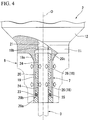
- the circumferential wall of the tube-shaped portion 7 includes an outer tube (an outer wall portion positioned on the outside in the radial direction of the fluid chamber 18 in the circumferential wall) 19 which is integrally formed with the tool main body 2, and an inner tube (an inner wall portion positioned on the inside in the radial direction of the fluid chamber 18 in the circumferential wall) 20 which is liquid-tightly fitted into the outer tube 19, and the fluid chambers 18 are formed between the outer tube 19 and the inner tube 20.
- the outer tube 19 is erected from the distal surface of the head attachment portion 11 of the tool main body 2 toward the distal side.
- the proximal end portion (connection portion) 19a which is connected to the head attachment portion 11 on the outer circumferential surface of the outer tube 19 is formed in a taper shape in which the diameter gradually increases toward the proximal side.
- a portion on the outer circumferential surface of the outer tube 19 except for the proximal end portion 19a has a constant diameter (outer diameter) in the direction of the axial line O.
- the inner diameter of a proximal end portion 19b of the inner circumferential surface of the outer tube 19 is larger than the inner diameter of the portion except for the proximal end portion 19b, and the portion except for the proximal end portion 19b has a constant diameter (inner diameter) in the direction of the axial line O.
- a mounting hole 21 which extends in the direction of the axial line O in the tool main body 2 and in which the mounting hole 21 opens toward the inner portion of the outer tube 19 is formed on the proximal side of the outer tube 19 in the tool main body 2, and the inner portion of the outer tube 19 and the inner portion of the mounting hole 21 communicate with each other.
- the inner diameter of the mounting hole 21 is smaller than the inner diameter of the outer tube 19, and is slightly larger than the inner diameter of the inner tube 20 which is fitted to the outer tube 19.
- the shank portion 6 of the reamer 3 may be inserted into the mounting hole 21.
- the inner tube 20 is detachably fitted into the outer tube 19. Specifically, an outer diameter of a distal portion 20a of the inner tube 20 is larger than that of a portion except for the distal portion 20a, and the portion of the inner tube 20 except for the distal portion 20a is inserted into the outer tube 19.
- the outer diameter of the distal portion 20a of the inner tube 20 is slightly smaller than the outer diameter of the portion except for the proximal end portion 19a of the outer tube 19, and the distal portion 20a on the outer circumferential surface of the inner tube 20 and the portion on the outer circumferential surface of the outer tube 19 except for the proximal end portion 19a are continued to each other without substantially steps in the direction of the axial line O.
- an end surface 20b which is formed between the distal portion 20a of the inner tube 20 and the portion except for the distal portion 20a and faces the proximal side comes into contact with a distal opening edge of the outer tube 19.
- a seal groove 23 and fluid accommodation grooves 24 are formed on the portion on the outer circumferential surface of the inner tube 20 except for the distal end portion 20a in this order toward the proximal end portion.
- the seal groove 23 is positioned closer to the distal end portion 20a than the fluid accommodation groove 24, and is disposed so as to be separated from the fluid accommodation groove 24.
- the seal groove 23 has annular shape which is recessed from the outer circumferential surface of the inner tube 20 inward in the radial direction and which is formed in the circumferential direction.
- a seal member 25 such as an annular O ring is disposed in the seal groove 23.
- the fluid accommodation groove 24 has an annular shape which is recessed from the outer circumferential surface of the inner tube 20 inward in the radial direction and extends in the circumferential direction, and the width of the fluid accommodation groove 24 in the direction of the axial line O is larger than the width of the seal groove 23.
- the thickness of a portion on the circumferential wall of the inner tube 20 at which the fluid accommodation groove 24 is positioned is the same as the thickness of a portion of the outer tube 19 which is positioned on the outside in the radial direction of the fluid accommodation groove 24.
- the plurality of fluid accommodation grooves 24 are formed on the outer circumferential surface of the inner tube 20 with intervals therebetween in the direction of the axial line O, and in the example of the present embodiment, two fluid accommodation grooves 24 are formed with intervals therebetween in the direction of the axial line O.
- two fluid accommodation grooves 24 are formed with intervals therebetween in the direction of the axial line O.
- a bottom surface (a surface facing outward in the radial direction) in the fluid accommodation groove 24 linearly expands in the direction of the axial line O, one side surface (wall surface) of the fluid accommodation groove 24 positioned close to the distal end portion of the tool main body 2intends toward the distal end portion of the tool main body 2, and the other side surface of the fluid accommodation groove 24 positioned close to the proximal end portion of the tool main body 2also intends toward the proximal end portion of the tool main body 2.
- a space which is formed by the fluid accommodation groove 24 of the inner tube 20 and the portion on the inner circumferential surface of the outer tube 19 facing the accommodation groove 24, is included in the fluid chamber 18. That is, in the present embodiment, the fluid chamber 18 includes annular fluid chamber portions 26 which extend in the circumferential direction in accordance with the shapes of the fluid accommodation grooves 24, and the plurality of annular fluid chamber portions 26 are provided in the inner portion of the circumferential wall of the tube-shaped portion 7 with intervals therebetween in the direction of the axial line O.
- the inner portion of the fluid chamber 18 is filled with liquid (fluid) such as oil, and although it is not particularly shown, the fluid chamber 18 includes a pressure transmission path which communicates with the inner portion of the tool main body 2 via at least one of the inner tube 20 and the outer tube 19 from the annular fluid chamber portion 26.
- the pressure transmission path is a channel which is formed (built in) in the tool main body 2 in a sealing state, one end of the channel of the pressure transmission path communicates with the annular fluid chamber portion 26, and the other end of the channel communicates with a pressure adjustment screw hole opening to the outer surface of the tool main body 2 and is sealed by a pressure adjustment screw (pressure adjustment means) which is screwed to the pressure adjustment screw hole.
- pressure (internal pressure) of the fluid inside the fluid chamber 18 increases or decreases by adjusting a screwing amount of the pressure adjustment screw with respect to the pressure adjustment screw hole.
- a portion except for the seal groove 23 and the fluid accommodation grooves 24 has a constant diameter (inner diameter) in the direction of the axial line O.
- the outer diameter of the portion on the outer circumferential surface of the inner tube 20 except for the distal portion 20a is approximately the same as the inner diameter of the portion on the inner circumferential surface of the outer tube 19 except for the proximal end portion 19b, and the portion on the outer circumferential surface of the inner tube 20 except for the distal portion 20a is fitted toward the proximal side while sliding with (the portion except for the proximal end portion 19b on) the inner circumferential surface of the outer tube 19.
- a proximal end portion 20c on the outer circumferential surface of the inner tube 20 has a chamfered shape in which the diameter gradually decreases toward the proximal side, and the proximal end portion 20c is positioned inside the proximal end portion 19b of the outer tube 19.
- the inner circumferential surface of the inner tube 20 has a constant diameter (inner diameter) in the direction of the axial line O.
- the inner diameter of the inner tube 20 is approximately the same as the outer diameter of the shank portion 6 of the reamer 3, and the reamer 3 is fitted to the tube-shaped portion 7 in a removable manner by fitting the shank portion 6 toward the proximal side while allowing the outer circumferential surface of the shank portion 6 of the reamer 3 to slide with the inner circumferential surface of the inner tube 20 of the tube-shaped portion 7.
- the reamer 3 is detachably fitted to the inside in the radial direction of the tube-shaped portion 7, and in the fitted state, the cutting edge portions 5 of the reamer 3 extend so as to protrude from the tube-shaped portion 7 toward the distal side.
- an inner wall portion and an outer wall portion (a portion of the inner tube 20 corresponding to the annular fluid chamber portion 26 in the direction of the axial line O and a portion of the outer tube 19 corresponding to the annular fluid chamber portion 26 in the direction of the axial line O) positioned on the inside and the outside in the radial direction of the annular fluid chamber portion 26 (fluid chamber 18) on the circumferential wall of the tube-shaped portion 7 can be elastically deformed in the radial direction according to a change in pressure of the fluid inside the annular fluid chamber portion 26.
- the outer wall portion (outer tube 19) is elastically deformed outward in the radial direction and is pressed to the head portion 9, and the inner wall portion (inner tube 20) is elastically deformed inward in the radial direction and is pressed to the reamer 3.
- the reamer 3 is fitted to the circumferential wall of the tube-shaped portion 7 from the inside in the radial direction and the head portion 9 is fitted to the circumferential wall from the outside in the radial direction. Accordingly, since the inner wall portion (inner tube 20) of the circumferential wall of the tube-shaped portion 7 is expanded so as to be elastically deformed to the inside in the radial direction, the tube-shaped portion 7 and the reamer 3 are pressed to each other and are fixed to each other so as not to be relatively moved, and since the outer wall portion (outer tube 19) of the circumferential wall of the tube-shaped portion 7 is expanded so as to be elastically deformed to the outside in the radial direction, the tube-shaped portion 7 and the head portion 9 are pressed to each other and are fixed to each other so as not to be relatively moved.
- rigidity of the circumferential wall of the tube-shaped portion 7 is set so as to be elastically deformed as described above and is lower than rigidity of each of the reamer 3 and the head portion 9.
- the rigidity of the circumferential wall of the tube-shaped portion 7 substantially increases.
- the head portion 9 is externally fitted to the tube-shaped portion 7 of the tool main body 2, and the head portion 9 is mounted on the head attachment portion 11 of the tool main body 2 by screwing the attachment screws 16 to the attachment screw holes 17. Moreover, at this time, the attachment screws 16 are temporarily fastened, and the attachment screws 16 may be permanently fastened after the tube-shaped portion 7, the head portion 9, and the reamer 3 described below are aligned, or at this time, the attachment screws 16 may not be permanently fastened.
- the reamer 3 is inserted into the tube-shaped portion 7, the proximal end portion of the reamer 3 abuts against an abutment portion (not shown) provided in the tool main body 2 (for example, in the mounting hole 21), or the pressure adjustment screws are screwed (the screwing amount with respect to the pressure adjustment screw hole is increased) in a state where the position of the reamer in the direction of the axial line O is adjusted in accordance with a mark or the like provided on the outer circumferential surface of the reamer 3, and the pressure of the fluid inside the fluid chamber 18 increases.
- each of a relative movement between the tube-shaped portion 7 and the head portion 9 and a relative movement between the tube-shaped portion 7 and the reamer 3 is regulated while the tube-shaped portion 7 of the tool main body 2, the head portion 9, and the reamer 3 are aligned in the radial direction so as to be coaxially disposed one another on the axial line O, and the tube-shaped portion 7, the head portion 9, the reamer 3 are firmly fixed as if they are integrated with each other.
- the head portion 9 and/or the reamer 3 is removed according to a procedure reverse to the above-described procedure and is replaced with another head portion 9 and/or reamer 3.
- the circumferential wall of the tube-shaped portion 7 is deformed so as to be restored, and the head portion 9 and the reamer 3 can be removed.
- the screwing of the attachment screw 16 with respect to the attachment screw hole 17 may be released (the attachment screw 16 may be removed).
- attachment and detachment operations of the head portion 9 and the reamer 3 with respect to the tube-shaped portion 7 of the above-described tool main body 2 are performed outside the machine tool (outside the machine).
- the present invention is not limited to this, and for example, in a state where the tool main body 2 is mounted on the main spindle of the machine tool, the head portion 9 and the reamer 3 may be attached to or detached from the tube-shaped portion 7 of the tool main body 2.
- the tube-shaped portion 7 is provided on the distal end portion of the tool main body 2, and by increasing the pressure of the liquid (fluid) inside the fluid chamber 18 formed in the inner portion of the circumferential wall of the tube-shaped portion 7 in the state where the reamer (hole machining tool core) 3 is fitted to the inside in the radial direction of the tube-shaped portion 7 and the head portion 9 is fitted to the outside in the radial direction of the tube-shaped portion 7, each of the inner wall portion and the outer wall portion (inner tube 20 and the outer tube 19) positioned on the inside in the radial direction and on the outside in the radial direction of the fluid chamber 18 of the circumferential wall is elastically deformed in the radial direction, and the tube-shaped portion 7, the reamer 3, and the head portion 9 are fixed to each other while being coaxially aligned with each other on the axial line O of the tool main body 2.
- the inner wall portion (inner tube 20 in the present embodiment) positioned on the inside in the radial direction of the fluid chamber 18 of the circumferential wall is deformed so as to be expanded inward in the radial direction, and the inner circumferential surface of the inner wall portion (inner circumferential surface of the inner tube 20) is pressed to the outer circumferential surface of the shank portion 6 of the reamer 3. Accordingly, the reamer 3 is adjusted such that the center axis C of the reamer 3 is accurately coincident with the axial line O of the tool main body 2.
- the outer wall portion (outer tube 19 in the present embodiment) positioned on the outside in the radial direction of the fluid chamber 18 of the circumferential wall of the tube-shaped portion 7 is deformed so as to be expanded outward in the radial direction, and the outer circumferential surface of the outer wall portion (outer circumferential surface of the outer tube 19) is pressed to the inner circumferential surface of the head portion 9. Accordingly, the head portion 9 is adjusted such that the center axis of the head portion 9 is accurately coincident with the axial line O of the tool main body 2.
- the tube-shaped portion 7 may be deformed (the diameter thereof may be increased) outward in the radial direction by a reaction force by which the inner wall portion presses the reamer 3, or a holding force with respect to the reamer 3 may not be sufficiently secured.
- the inner wall portion (inner tube 20) positioned on the inside in the radial direction of the circumferential wall of the tube-shaped portion 7 is elastically deformed inward in the radial direction
- the outer wall portion (outer tube 19) positioned on the outside in the radial direction of the circumferential wall is elastically deformed outward in the radial direction
- the reamer 3 and the head portion 9 are pressed to each other, and effects which cancel out the reaction forces each other are obtained. Accordingly, it is possible to effectively prevent the deformation of the tube-shaped portion 7, and it is possible to sufficiently secure tool rigidity by securing the holding force with respect to the reamer 3.
- the axial alignment and the fixation among the tube-shaped portion 7, the reamer 3, and the head portion 9 are performed by a simple operation such as increasing the pressure of the fluid in the fluid chamber 18, workability is improved. That is, for example, unlike the present embodiment, in the related art, when the reamer or the head portion is attached to the tube-shaped portion of the tool main body, an adjustment screw which fixes the position of the reamer or the head portion while aligning the reamer or the head portion in the axial direction, or the like is necessary. However, in the present embodiment, the adjustment screw is not required, and workability with respect to the axial alignment and the fixation of the reamer is remarkably improved.
- setting of the cutting tool 1 is effectively performed in a short time, man-hours decrease, the workability increases, cutting is performed in high efficiency, and productivity is improved.
- the reamer 3 and the head portion 9 may be removed from the tube-shaped portion 7 of the tool main body 2 by decreasing the pressure of the fluid inside the fluid chamber 18. Accordingly, the inner wall portion (inner tube 20) and the outer wall portion (outer tube 19) which have been elastically deformed as described above are deformed so as to be restored, and it is possible to simply remove the reamer 3 and the head portion 9 from the tube-shaped portion 7.
- the reamer 3 is detachably mounted on the tool main body 2 using the hydro-chuck structure, and it is possible to sufficiently secure the tool rigidity while increasing an attachment and detachment operability and accuracy of the axial alignment.
- the head portion 9 is detachably mounted on the distal end portion of the tool main body 2, that is, the tool main body 2 and the head portion 9 can be divided into separate units while the rigidity of the distal end portion of the tool main body 2 is sufficiently secured. Accordingly, the following effects are obtained.
- the plurality of head portions 9 in which the shapes of the cutting edges 4 or diameters of rotation paths of the cutting edges 4 around the axial line O are different from each other can be prepared, and according to the shapes of the opening portions (shapes of the valve seats, diameters of the valve seats, or the like) of various machined holes, or a kind of machining (rough machining, finishing, or the like), the head portions 9 can be selectively exchanged with respect to one set of the tool main body 2 and the reamer 3. Accordingly, it is possible to easily cope with small quantities of various different types of production while decreasing cost of facilities, and when the head portion 9 or the cutting edge 4 is damaged, it is possible to cope with the damage by replacing the head portion 9, and it is possible to reduce costs.
- the fluid chamber 18 includes the annular fluid chamber portion 26 which extends around the direction of the axial line (in the circumferential direction) between the outer wall portion (outer tube 19) and the inner wall portion (inner tube 20) of the circumferential wall of the tube-shaped portion 7, operations due to the provision of the above-described fluid chamber 18 are obtained over the entire region in the circumferential direction on the inside and the outside in the radial direction of the tube-shaped portion 7, and the tube-shaped portion 7 and the reamer 3, and the tube-shaped portion 7 and the head portion 9 are fixed so as to firmly and reliably come into close contact with each other over the entire region in the circumferential direction.
- the above-described effects obtained by provision of the annular fluid chamber portions 26 to the fluid chamber 18 are obtained at a plurality of locations with intervals therebetween in the direction of the axial line O in the tube-shaped portion 7, and preferably, reliability increases.
- the circumferential wall of the tube-shaped portion 7 includes the outer tube (outer wall portion) 19 which is integrally formed with the tool main body 2, and the inner tube (inner wall portion) 20 which is liquid-tightly fitted into the outer tube 19, and the fluid chamber 18 is formed between the outer tube 19 and the inner tube 20. Accordingly, it is possible to simply configure the circumferential wall of the tube-shaped portion 7, and it is possible to accurately form the fluid chamber 18 in a desired shape.
- the axial alignment of the reamer 3 is not particularly required, and it is possible to accurately align the reamer 3 on the axial line O of the tool main body 2 by only chucking (holding and fixing) the reamer 3 into the tube-shaped portion 7.
- the present invention is not limited to the above-described embodiment, and various modifications may be applied to the present invention within a scope which does not depart from the gist of the present invention.
- the hole machining tool core is the reamer 3.
- the present invention is not limited to this, for example, the hole machining tool core may be a gun drill (drill) in addition to the reamer 3.
- the circumferential wall of the tube-shaped portion 7 has a double tube-shaped structure which separately includes the outer tube (outer wall portion) 19 and the inner tube (inner wall portion) 20.
- the present invention is not limited to this, and for example, the circumferential wall may have a double tube-shaped structure in which the outer tube 19 and the inner tube 20 are integrally formed.
- the fluid chamber 18 includes the plurality of annular fluid chamber portions 26 which extend around the axial line O and are provided with intervals therebetween in the direction of the axial line O is described.
- the prevent invention is not limited to this. That is, for example, the fluid chamber 18 may include a C-shaped fluid chamber portion having a C shape around the axial line O in addition to the annular shape, or may include fluid chamber portion having other shapes.
- the number of the annular fluid chamber portions 26 is not limited to two, which is described in the embodiment. That is, the number of the annular fluid chamber portions 26 is three or more or only one.
- the inner portion of the fluid chamber 18 is filled with liquid (fluid) such as oil.
- liquid such as oil.
- the kind of the fluid which fills the inner portion of the fluid chamber 18 is not limited to the liquid such as oil.
- the cutting inserts 14 having the cutting edges 4 are detachably disposed on the insert attachment seats of the notch portion 13 of the head portion 9 .
- the present invention is not limited to this, and for example, the cutting edge portions having the cutting edges 4 may be integrated with the outer circumferential portion of the head portion 9 by brazing or the like so as to be not removed from the outer circumferential portion.
- the head portion 9 is detachably mounted on the distal end portion of the tool main body 2.
- the present invention is not limited to this. That is, the head portion 9 may be undetachably integrated with the tool main body 2 using welding, bonding, brazing (a case where the entire head portion 9 is formed of sintered hard alloy, or the like), or the like.
- a tube-shaped portion is provided on a distal portion of a tool main body, and by increasing pressure of liquid (fluid) inside a fluid chamber formed in the inner portion of a circumferential wall of the tube-shaped portion in a state where a hole machining tool core is fitted to an inside in a radial direction of the tube-shaped portion and a head portion is fitted to an outside in the radial direction of the tube-shaped portion, each of an inner wall portion and an outer wall portion positioned on the inside in the radial direction and on the outside in the radial direction of the fluid chamber of the circumferential wall is elastically deformed in the radial direction, and the tube-shaped portion, the hole machining tool core, and the head portion are fixed to each other while being coaxially aligned with each other on an axial line of the tool main body.
- the present invention has industrial applicability.
Applications Claiming Priority (2)
| Application Number | Priority Date | Filing Date | Title |
|---|---|---|---|
| JP2013190963A JP5725111B2 (ja) | 2013-09-13 | 2013-09-13 | 切削工具 |
| PCT/JP2014/074176 WO2015037697A1 (ja) | 2013-09-13 | 2014-09-12 | 切削工具 |
Publications (1)
| Publication Number | Publication Date |
|---|---|
| EP3045244A1 true EP3045244A1 (en) | 2016-07-20 |
Family
ID=52665795
Family Applications (1)
| Application Number | Title | Priority Date | Filing Date |
|---|---|---|---|
| EP14843414.5A Withdrawn EP3045244A1 (en) | 2013-09-13 | 2014-09-12 | Cutting tool |
Country Status (6)
| Country | Link |
|---|---|
| US (1) | US20160214183A1 (zh) |
| EP (1) | EP3045244A1 (zh) |
| JP (1) | JP5725111B2 (zh) |
| KR (1) | KR20160053924A (zh) |
| CN (1) | CN105517740A (zh) |
| WO (1) | WO2015037697A1 (zh) |
Cited By (2)
| Publication number | Priority date | Publication date | Assignee | Title |
|---|---|---|---|---|
| WO2019170378A1 (de) * | 2018-03-09 | 2019-09-12 | Kyocera Unimerco Tooling A/S | Kombinationswerkzeug und werkzeughalter für ein kombinationswerkzeug |
| IT201900020865A1 (it) * | 2019-11-12 | 2021-05-12 | Gerardo Lepore | Dispositivo di bloccaggio idraulico di un utensile per una macchina utensile |
Families Citing this family (7)
| Publication number | Priority date | Publication date | Assignee | Title |
|---|---|---|---|---|
| JP6769009B2 (ja) * | 2015-11-16 | 2020-10-14 | 住友電工ハードメタル株式会社 | 切削工具および切削装置 |
| DE102017104199A1 (de) * | 2017-03-01 | 2018-09-06 | Gühring KG | Senkwerkzeug, Werkzeuganordnung und Verfahren |
| CN106903352A (zh) * | 2017-04-25 | 2017-06-30 | 四川天虎工具有限责任公司 | 一种双面倒角钻孔刀具 |
| CN107138783A (zh) * | 2017-06-19 | 2017-09-08 | 浙江优傲智能科技有限公司 | 一种易于更换的刀具 |
| CN112449616B (zh) * | 2018-07-20 | 2023-10-17 | 本田技研工业株式会社 | 加工工具 |
| WO2020216997A1 (en) * | 2019-04-24 | 2020-10-29 | Aalto University Foundation Sr | Arrangement for providing centre displacement in a machine tool |
| CN111390215A (zh) * | 2020-05-12 | 2020-07-10 | 济宁捷合机械有限公司 | 液压夹紧钻夹头 |
Family Cites Families (14)
| Publication number | Priority date | Publication date | Assignee | Title |
|---|---|---|---|---|
| US4093052A (en) * | 1974-01-23 | 1978-06-06 | Forenade Fabriksverken | Fluid actuated coupling assembly |
| SE7907277L (sv) * | 1979-08-31 | 1981-03-01 | Ffv Industriprodukter Ab | Friktionsforband |
| IT1149490B (it) * | 1982-01-27 | 1986-12-03 | Giovanni Gattrugeri | Testata espandibile per bobine in genere |
| JPH0212007Y2 (zh) * | 1985-10-25 | 1990-04-04 | ||
| JPH0642003U (ja) * | 1992-11-17 | 1994-06-03 | 博充 豊本 | 流体圧チャック |
| US7465120B2 (en) * | 2002-04-01 | 2008-12-16 | Rivin Evgeny I | Wedge mechanism |
| SE525539C2 (sv) * | 2002-07-17 | 2005-03-08 | Etp Transmission Ab | Hydromekanisk fastspänningsanordning med samverkande konytor |
| FR2873944B1 (fr) * | 2004-08-09 | 2006-10-06 | Epb Sa | Mandrin porte-fraise |
| DE102006016290C5 (de) * | 2006-04-06 | 2022-02-17 | Gühring KG | Mehrteiliges Schaftwerkzeug, insbesondere Feinbearbeitungswerkzeug |
| JP4872534B2 (ja) * | 2006-08-24 | 2012-02-08 | 三菱マテリアル株式会社 | 切削工具 |
| SE530537C2 (sv) * | 2006-11-02 | 2008-07-01 | Etp Transmission Ab | Hydromekanisk fastspänningsanordning |
| JP2012076199A (ja) | 2010-10-05 | 2012-04-19 | Daishowa Seiki Co Ltd | ハイドロチャック |
| EP2716391B1 (en) * | 2011-05-25 | 2020-07-08 | Big Daishowa Seiki Co., Ltd. | Holder device |
| DE102012209312A1 (de) * | 2012-06-01 | 2013-12-05 | Gühring Ohg | Modularer Werkzeughalter |
-
2013
- 2013-09-13 JP JP2013190963A patent/JP5725111B2/ja active Active
-
2014
- 2014-09-12 WO PCT/JP2014/074176 patent/WO2015037697A1/ja active Application Filing
- 2014-09-12 EP EP14843414.5A patent/EP3045244A1/en not_active Withdrawn
- 2014-09-12 CN CN201480049409.0A patent/CN105517740A/zh active Pending
- 2014-09-12 KR KR1020167005894A patent/KR20160053924A/ko not_active Application Discontinuation
- 2014-09-12 US US14/917,955 patent/US20160214183A1/en not_active Abandoned
Non-Patent Citations (1)
| Title |
|---|
| See references of WO2015037697A1 * |
Cited By (3)
| Publication number | Priority date | Publication date | Assignee | Title |
|---|---|---|---|---|
| WO2019170378A1 (de) * | 2018-03-09 | 2019-09-12 | Kyocera Unimerco Tooling A/S | Kombinationswerkzeug und werkzeughalter für ein kombinationswerkzeug |
| IT201900020865A1 (it) * | 2019-11-12 | 2021-05-12 | Gerardo Lepore | Dispositivo di bloccaggio idraulico di un utensile per una macchina utensile |
| WO2021094869A1 (en) * | 2019-11-12 | 2021-05-20 | Lepore Gerardo | A hydraulic clamping device of a tool for a machine tool |
Also Published As
| Publication number | Publication date |
|---|---|
| US20160214183A1 (en) | 2016-07-28 |
| JP2015054385A (ja) | 2015-03-23 |
| JP5725111B2 (ja) | 2015-05-27 |
| KR20160053924A (ko) | 2016-05-13 |
| CN105517740A (zh) | 2016-04-20 |
| WO2015037697A1 (ja) | 2015-03-19 |
Similar Documents
| Publication | Publication Date | Title |
|---|---|---|
| EP3045244A1 (en) | Cutting tool | |
| US9656324B2 (en) | Cartridge for a grooving tool holder, corresponding grooving tool holder, kit and assembly thereof | |
| US20090196698A1 (en) | Tool system | |
| US9827619B2 (en) | Machining tool and cutting head for the machining tool | |
| US20160067786A1 (en) | Toolholder with clamp having fluid flow passages, and tool including such a toolholder | |
| US11065691B2 (en) | Cutting tool and method of manufacturing machined product using the same | |
| US20090120240A1 (en) | Method for manufacturing drill head | |
| JP2019509183A (ja) | 切削ツール | |
| US20180369976A1 (en) | Cooling system and method for machine tools | |
| KR20070061520A (ko) | 밀링커터용 홀더의 맨드릴 | |
| JP4872534B2 (ja) | 切削工具 | |
| CN112449616B (zh) | 加工工具 | |
| US11000905B2 (en) | Adapter sleeve | |
| US20220193841A1 (en) | Boring bar arrangement | |
| JP5790566B2 (ja) | 切削ヘッドの締結機構及びこれを用いたヘッド交換式切削工具 | |
| KR20200036878A (ko) | 절삭 공구 및 조절 장치가 장착된 절삭 공구를 위한 조절 장치 | |
| JP2009154220A (ja) | 切削工具 | |
| JP2015039753A (ja) | 油圧チャック構造およびその製造方法 | |
| JP2009291858A (ja) | 穴加工工具 | |
| JP2005335015A (ja) | プリセットスクリュー、工具ホルダおよび流体供給方法 | |
| JP5923646B1 (ja) | 焼嵌め式工具ホルダおよび刃物のチャッキング構造 | |
| JP2016175164A (ja) | ホルダ及び切削工具 | |
| JP2013202749A (ja) | ボーリングバー | |
| JP2019177443A (ja) | 切削工具用カートリッジ、切削工具 | |
| JP7416363B2 (ja) | ハイドロチャック |
Legal Events
| Date | Code | Title | Description |
|---|---|---|---|
| PUAI | Public reference made under article 153(3) epc to a published international application that has entered the european phase |
Free format text: ORIGINAL CODE: 0009012 |
|
| 17P | Request for examination filed |
Effective date: 20160315 |
|
| AK | Designated contracting states |
Kind code of ref document: A1 Designated state(s): AL AT BE BG CH CY CZ DE DK EE ES FI FR GB GR HR HU IE IS IT LI LT LU LV MC MK MT NL NO PL PT RO RS SE SI SK SM TR |
|
| AX | Request for extension of the european patent |
Extension state: BA ME |
|
| DAX | Request for extension of the european patent (deleted) | ||
| STAA | Information on the status of an ep patent application or granted ep patent |
Free format text: STATUS: THE APPLICATION HAS BEEN WITHDRAWN |
|
| 18W | Application withdrawn |
Effective date: 20170208 |