EP3045209A2 - Dispositif de protection contre les chutes et procede destine a eviter un traumatisme provoque par la suspension - Google Patents
Dispositif de protection contre les chutes et procede destine a eviter un traumatisme provoque par la suspension Download PDFInfo
- Publication number
- EP3045209A2 EP3045209A2 EP16000028.7A EP16000028A EP3045209A2 EP 3045209 A2 EP3045209 A2 EP 3045209A2 EP 16000028 A EP16000028 A EP 16000028A EP 3045209 A2 EP3045209 A2 EP 3045209A2
- Authority
- EP
- European Patent Office
- Prior art keywords
- harness
- person
- tether
- loops
- arm
- Prior art date
- Legal status (The legal status is an assumption and is not a legal conclusion. Google has not performed a legal analysis and makes no representation as to the accuracy of the status listed.)
- Granted
Links
Images

Classifications
-
- A—HUMAN NECESSITIES
- A62—LIFE-SAVING; FIRE-FIGHTING
- A62B—DEVICES, APPARATUS OR METHODS FOR LIFE-SAVING
- A62B35/00—Safety belts or body harnesses; Similar equipment for limiting displacement of the human body, especially in case of sudden changes of motion
- A62B35/0006—Harnesses; Accessories therefor
- A62B35/0025—Details and accessories
-
- A—HUMAN NECESSITIES
- A62—LIFE-SAVING; FIRE-FIGHTING
- A62B—DEVICES, APPARATUS OR METHODS FOR LIFE-SAVING
- A62B1/00—Devices for lowering persons from buildings or the like
- A62B1/06—Devices for lowering persons from buildings or the like by making use of rope-lowering devices
- A62B1/16—Life-saving ropes or belts
-
- A—HUMAN NECESSITIES
- A62—LIFE-SAVING; FIRE-FIGHTING
- A62B—DEVICES, APPARATUS OR METHODS FOR LIFE-SAVING
- A62B35/00—Safety belts or body harnesses; Similar equipment for limiting displacement of the human body, especially in case of sudden changes of motion
- A62B35/0006—Harnesses; Accessories therefor
- A62B35/0018—Full body harnesses covering at least shoulders and thighs
-
- A—HUMAN NECESSITIES
- A62—LIFE-SAVING; FIRE-FIGHTING
- A62B—DEVICES, APPARATUS OR METHODS FOR LIFE-SAVING
- A62B35/00—Safety belts or body harnesses; Similar equipment for limiting displacement of the human body, especially in case of sudden changes of motion
- A62B35/0006—Harnesses; Accessories therefor
- A62B35/0025—Details and accessories
- A62B35/0031—Belt sorting accessories, e.g. devices keeping the belts in comfortable positions
-
- A—HUMAN NECESSITIES
- A62—LIFE-SAVING; FIRE-FIGHTING
- A62B—DEVICES, APPARATUS OR METHODS FOR LIFE-SAVING
- A62B35/00—Safety belts or body harnesses; Similar equipment for limiting displacement of the human body, especially in case of sudden changes of motion
- A62B35/0006—Harnesses; Accessories therefor
- A62B35/0025—Details and accessories
- A62B35/0037—Attachments for lifelines and lanyards
-
- A—HUMAN NECESSITIES
- A62—LIFE-SAVING; FIRE-FIGHTING
- A62B—DEVICES, APPARATUS OR METHODS FOR LIFE-SAVING
- A62B35/00—Safety belts or body harnesses; Similar equipment for limiting displacement of the human body, especially in case of sudden changes of motion
- A62B35/0043—Lifelines, lanyards, and anchors therefore
- A62B35/0075—Details of ropes or similar equipment, e.g. between the secured person and the lifeline or anchor
Definitions
- the invention relates to a device for fall protection of persons comprising a harness with arm loops and leg loops, wherein on the harness, in particular on the arm loops at least a first securing eye is arranged, to which a safety rope is attached or attached, in particular wherein the at least one first securing eye in Back region, preferably in the neck region of the further preferably arranged there crossed arm loops is arranged.
- Such a harness may e.g. a belt construction, in which two arm loops and two leg loops are provided, wherein an arm loop and a leg loop on a respective body side in the belt guide, in particular by crossing a belt in the lateral body area merge into one another.
- Arm and leg loops of a respective body side can be, e.g. be realized by a substantially 8-shaped guide a belt.
- a self-integrating belt it is not absolutely necessary for a self-integrating belt to form such a crossed loop, but it can also be a composite of several connected belt pieces.
- a self-integrating belt it is not absolutely necessary for a self-integrating belt to form such a crossed loop, but it can also be a composite of several connected belt pieces.
- an arm loop area and a leg loop area on each side of the body respectively separate Gurt vinegar be used, which are interconnected, for example by releasable connector.
- common harnesses may also provide a hip belt and / or chest strap, in particular the connection of arm loops and leg loops and / or the connection of the straps from one body side to the other makes.
- a hip belt and / or chest strap in particular the connection of arm loops and leg loops and / or the connection of the straps from one body side to the other makes.
- two arm loops with a hipbelt and two leg loops can be connected with this hipbelt.
- the respective connections between the loops and a hip belt may e.g. also done via straps.
- the invention is basically applicable to any type of harness, which has at least one pair of arm loops and leg loops, regardless of how their connection is made with each other.
- the position indication "in the back region” or “in the neck region” refers to the designation of the position of the at least one eyelet when the harness has been correctly and correctly applied by a person. This also applies to the following location information. Other location or direction refers to a standing person or person with a head up and feet down.
- a hip belt is understood to be a belt that a person can put around their hips. Such a belt can be opened and closed and adjustable in the circumferential length. The same applies to a possible chest belt.
- a doctorssinein monkeit can also be provided in the loops of arms and / or legs.
- a securing eye is still understood any element that is suitable, a connection between safety rope and harness, or also to produce the tether invention described later.
- a metal ring, a belt loop or a snap hook can form such a securing eye.
- Devices of this type are known in the art and are used to secure persons working at heights from falling, namely by attaching a safety cable at one of its ends to at least one first securing eye of the harness and with the other end to one fixed fuse element. So a working person is practically roped and pulls the safety rope at work. Since the safety rope is preferably fastened to the harness in the upper back or neck area, it does not interfere further in the working area lying in front of the person.
- the rope is tightened, possibly taking advantage of a damping effect of a arranged in the rope damping element so that the enthroned in the harness person is caught by the tightening rope and hereafter hanging on the safety rope, ideally without himself to have hurt.
- the arrangement or attachment of the safety rope to the harness is preferably selected in such fall protection that the rope engages the aforementioned at least one first eyelet in a neck or shoulder region of the harness, so that the abrupt braking force as well as by the free hanging generated weight is transmitted both over the arm loops and the two leg loops, if necessary. Also on the chest and / or hip belt on the body of the person hanging. By this power transmission to several body areas of the person is essentially avoided that the person carries off physical damage in a crash.
- fall protection can prevent a person from falling directly to the ground due to a fall, there is still the problem that an orthostatic shock or a so-called hanging trauma occurs after an extended period of hanging on the safety rope, usually at the latest after 20 minutes. which can also lead to death in the person.
- an orthostatic shock or a so-called hanging trauma occurs after an extended period of hanging on the safety rope, usually at the latest after 20 minutes. which can also lead to death in the person.
- it is therefore absolutely necessary to free a person hanging very quickly from the hanging position by rescue, to avoid such Hängetrauma and associated health problems and even death.
- this object is achieved in that in the front region of the harness, at least a second securing eye is arranged, on which a tether is fastened or fastened and on the harness, in particular above a possibly hip belt, in particular on at least one of the arm loops, a holding element is arranged, with which the tether in the unloaded by the weight of a person state close to the harness, especially the harness, preferably at least one arm loop contacting in a holding position preserved or is held and is solvable in the burdened by the weight of a person state of the retaining layer.
- a separate to the safety rope and in particular to the safety rope (at least above the body) parallel tether which at one in the front Fixed portion of the hanging person arranged belt portion of the harness is tightened after the crash and thereby relieves the safety rope of the weight of the person and the tether is loaded by the weight of the person, so that the person transferred into a seated in leg loops of the harness position we d.
- the said front region of the harness may be formed in the device as well as the method by a belt region of the harness which runs on the front body side of the person, e.g. through the front hip or abdominal region of a hip belt, in particular the single or one of two waist straps of the harness, or through an area at the front of a chest belt or an area at the front of one or both arm loops.
- the front side of the body is understood to be any part of the body which, in a straight line of vision, is located in front of the body's center of gravity, in particular in front of the body anatomical frontal plane of the body, so that by redistributing the body load from the safety rope to the tether automatically rotation of the body of the person takes place so that the head to the rear and the feet are relocated to the front.
- Such a rope is fastened to the harness according to the above-described device with a holding element so that it is set close to the harness or close to the body of the person carrying the harness, z.
- the harness in particular an arm loop or both arm loops contacted here and thereby has a holding position in which this additional second rope does not bother a person at work, as it despite an arrangement in front of the abdominal / chest area of the person not in the work area z.
- B. in the work area reached by the hands of the person is reached, because it is held in the holding position close to the harness, so close to the body.
- such a tether is initially arranged completely passively on the device for fall protection during work and also after a crash.
- this additional tether is tightened, for example, by being caught by a winch or by another person or is even tightened by the crashed person himself, so that As a result, the weight of the person, which is initially intercepted by the safety rope, then transfers to the tether and thereby the tether is removed from the previous holding position.
- a person may wear the tether e.g. self-tightening, when an upper, ie person-upwards, cable section of the tether on at least one over-person pulley, e.g. is arranged stationary, is returned to the person.
- the person can pull himself up the tether, which is particularly simple if the deflection is not only by a single pulley, but by a staggering pulley construction.
- the tether is actively used only after a crash, and it may be provided according to a preferred embodiment of the device, that the holding element is designed so that the tether is released from the holding position under load by the weight of a person by a detachment the retaining element of the harness, in particular of an arm loop or by releasing the tether from the holding element, which the tether example partially encloses.
- the holding element is tubular or sleeve-shaped, so that the tether can be passed through the holding element, wherein the retaining element may be made for example of a textile and wherein the connection of the holding element to the harness or the hose - Or the sleeve casing of the holding element has a predetermined breaking point, which breaks under the burden of the weight of a person, for example, a hook and loop fastener.
- the device according to the invention can further preferably provide that the tubular or sleeve-shaped retaining element extends along a front, breast-side belt portion of an arm loop, in particular when the tether is guided by the retaining element to or at least to the vicinity of the first securing eye.
- the tether is indeed carried over the abdominal and chest area of a person carrying the harness, but is here, as long as it is not active, in the aforementioned holding position and does not interfere in the working area of the person and can then, for example from the first securing eye, at which the safety rope is attached, are guided substantially parallel to this to an attachment point, in particular to that on which the safety rope is attached or in the vicinity.
- Such a holding device may e.g. be formed by a shoulder pad that can be wrapped around one or both arm loops.
- a shoulder pad may be circumferentially wrapped around the respective arm loop and closed, e.g. through a Velcro closure.
- the tether can also be inserted into this pad and this can be closed afterwards.
- the device according to the invention can provide in one possible embodiment that there is only one pair of arm loops and a pair of leg loops on the harness, in particular if necessary connected by a hip belt, in which case the at least one securing eyelet in the neck region of the arm loops of this preferably crossed there Harness is arranged and the at least one second securing eye is attached to the front waist or abdominal area or chest area of the person on the harness, preferably on the waist belt, more preferably in the center of the body, ie in particular in the anatomical sagittal plane.
- the invention may also provide that the tether splits at its lower end facing the person into two pieces of rope which on both sides of the person's sagittal plane on the harness, but still in the front region, ie before the center of gravity or in front of the anatomical frontal plane attached to the harness.
- the attachment of the lower ends of the two pieces of rope can be made laterally on respective second securing eyelets on a hip belt or also on the front in the chest region of both arm loops.
- the location of the split of the tether is located so that this location is in the sitting after a crash held position of the person above the head.
- the splitting can be realized by a preferably rigid strap on which the upper portion of the tether is centrally attached and at the outer ends of the two pieces of rope the lower portion of the tether are attached.
- a distance between the cable pieces can be effected by the bracket, preferably such that the head of a person passes through this distance range between the cable pieces.
- the device can also provide that the harness is formed in two parts and comprises a first harness part and a second harness part, in particular, which can be connected to each other, e.g. by straps, wherein the first harness part comprises a first hip belt, two arm loops connected to the first hip belt, and a first pair of two leg loops connected to the first hip belt, the at least one first securing eye being arranged on the arm loops of this first harness part.
- Such a first harness part can basically correspond to a fall arrest device known from the prior art.
- the second harness part can now have a second hip belt and a second pair of two leg loops connected to the second hip belt, the at least one second safety eye being arranged on the second hip belt or the second pair of leg loops, to which the tether can be fastened or fastened ,
- Such a design of the harness of two harness parts has the advantage that the two harness parts can be optimally adapted separately to their respective function, namely the first harness part to the function to intercept a case of a falling person and the forces optimally on the body of the falling Person to distribute, wherein the second harness part in the training of hipbelt and leg loops can be optimized to achieve a particularly anatomically favorable seating position with this harness part of a person who hangs on the second safety eye on the tether after its activation.
- the second harness part can also be offered as a retrofit product to be able to retrofit existing harnesses with the function of the invention.
- a preferred embodiment, which takes up the execution of the split support cable can provide that the tether is formed in several parts with an upper cable section and a lower cable section facing the harness, wherein the lower cable section comprises two side by side, in particular parallel spaced, preferably elastically flexible cable pieces , which are connected to the upper cable section, in particular via a bracket defining the distance, wherein the lower ends of the cable pieces are connected via a respective second securing lug to a front region of the harness, preferably the front region of the arm loops.
- the second securing eyelets may here be designed such that the straps of the arm loops can be fastened to them, e.g. in that a belt piece of a respective arm loop is bent into a loop and this is passed through the recess of the securing eye. Thereafter, a cross bar can be guided through the formed belt loop, which prevents the retraction of the loop from the securing eye.
- the invention can provide that only the preferably elastic cable pieces of the lower cable section of the multi-part tether are held in the holding element, in particular in each case to a respective arm loop own area of the holding element.
- the above-mentioned bracket can be in the inactive position of the tethers, e.g. be arranged in the neck area.
- a separate leg loop can be fastened or at least attachable via an intermediate belt, in particular the intermediate belt can be detachably fastened to a connector of the respective cable piece. So must the leg loops, which for sitting hold the crashed person may not already be initially arranged on the harness, but can be attached there only when a crash has occurred.
- the invention has the advantage that a separate retrofitting of such previously described lower cable section, which is provided to be connected to an upper cable section to form a multi-part tether, as well as a simple retrofit for existing harnesses is possible to form a device according to the invention.
- Such a retrofit kit for harnesses may include in addition to such a lower cable section and a holding element and / or a simple rope as the upper rope section to form a total device according to the invention.
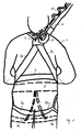
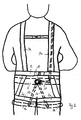
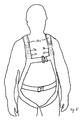
- the Fig. 1 shows first in back view of a person 1 a fall protection with a harness, which is applied in this representation to the person, this harness has a hip belt 2 and two arm loops 3a and 3b, the belt portions of these two arm loops emanating from the hip belt 2, respectively the person's shoulder are guided and returned to the waist belt.
- this representation shown here, the embodiment is such that the arm loops are guided in the upper back or neck area of the person crossing each other and in this crossing region a first securing eye 4 is arranged, in which, for example, with a snap hook 5, a safety rope is attached.
- a first pair of leg loops 7a and 7b is further secured, through which pass the legs of the person.
- the embodiment here additionally comprises, according to the invention, a further harness part shown here in dashed lines, comprising a second hip belt 8 and two further leg loops 9a and 9b.
- This second pair of leg loops 9a, 9b is here spaced from the first pair of leg loops 7a, 7b towards the person's feet.
- the hip belt 8 may be integrally formed with the waist belt 2, or both waist belts 2 and 8 are separately but at least connected, e.g. By intervening straps or hip belt 2 and 8 are formed by a single hip belt simultaneously, in particular, thus combining both functions (fall protection and Hängetraumavermeidung).
- a second securing eye 10 is arranged, on which an additional tether 11, for example, also attached with a snap hook.
- This tether 11 is here, starting from the second securing eye 10 along the extension of one of the two arm loops, here the arm loop 3b to the shoulder and out into the area of the first securing eye 4, as it Fig. 1 again from the back represents.
- the additional tether 11 is fixed in a holding position by means of a retaining element not shown here.
- This retaining element can in a simplest case, for. B. be a thread with which this rope attached to the belt area of the arm loop 3b, which is located in the abdominal / chest area of the person wearing, eg by sewing or looping is, so that upon activation, ie when a force load of this rope ruptures this thread and the tether 11 from the arm loop 3b triggers.
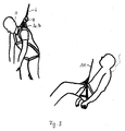
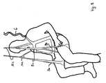
- the Fig. 3 shows the use of the in the Fig. 1 and 2 shown fall protection, namely in the Fig. 3 top left first, the situation in which the person has crashed 1 and hanging on the safety rope 6, which is attached via the first securing eye 4 in the neck area to the arm loops 3a and 3b.
- Fig. 3 bottom right shows that the crashed person is transferred by the rearrangement of the weight of the safety rope 6 on the tether 11 in an anatomically favorable sitting position in which a suspended trauma is avoided.
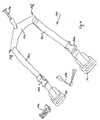
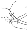
- FIG. 4 is essentially the lower cable section 11 b of a multi-part tether 11 according to the invention shown. Upwards to the right, the upper tether portion 11a leads away from the person. This upper section is essentially a simple rope.
- the lower portion comprises a bracket 11d, at the center of the upper cable section 11a is fixed and at the two outer ends 11f each one down to the harness of the person leading rope piece 11c is attached.
- This rope piece 11c may preferably be elastic in each case, e.g. include an elastic band or be formed from this. Of course, a non-stretchable design of the pieces of rope is possible.
- the second mentioned safety eyes 10 are respectively formed, through which the straps of arm loops of a harness can be passed in a loop and secured against retraction with the crossbars 10 a.
- the type of attachment between the pieces of rope and the arm loops is not limited to this type shown, but can also be done by other types of safety lugs.
- the connectors 11 e are provided to secure separate leg loops thereto.
- FIG. 5 visualized the lower cable section 11 b in dashed lines after attachment to the harness, or here specifically to the two arm loops 3a, 3b.
- the pieces of rope 11 c are placed on the front portion to over the shoulder back to the neck area, where according to FIG. 6 the bracket 11d is arranged, which connects the cable pieces 11c with the upper cable section 11a, in particular in this case also defines a distance between the cable pieces.
- This guide takes place at least in the front region of the arm loop by a holding element, not shown here, with which the cable pieces 11 c are held close to the body when not in use, in particular in contact with the respective Armschlaufe3a, 3b.
- a holding element may be formed by a tubular or sleeve-like preferably textile element, which can be wrapped around an arm loop and the respective rope piece and closed, for example with a hook-and-loop fastener.
- the upper cable section 11a of the multi-part tether 11 according to the invention extends upwards away.
- the safety rope is not shown here for reasons of clarity. It would be attached to the securing eye 4.
- FIG. 7 Visualizes the situation after a person crashes. This first depends on the safety rope 6, which is connected via the eyelet 4 with the harness.
- the person 1 himself pulls on the upper tether portion 11a returned to the person and thereby expands the elastic rope pieces 11c, so that the temples 11d are guided to a position above the head.
- the head can in this case be passed through the distance between the cable sections 11c, so that the bracket reaches a position above and preferably in front of the head.
- By acting on the pieces of rope 11 c forces they are pulled out of the holder on the arm loops 3a, 3b, for example, because their hook and loop fasteners rupture.
- FIG. 8 shows the situation in the relocated position.
- the person now hangs only on tether 11 on the rope pieces 11 c, the safety cable 6 is relieved.
- the connectors 11e which are arranged on the cable pieces 11c, separate leg loops 9a, 9b are fastened, which the person himself may have made.
- the person can first run the loops over the legs, eg, open the loops therefor and close them again and then attach them to the connectors 11e via the belt elements 9c. This puts the person in a sitting position without the risk of trauma.
Landscapes
- Health & Medical Sciences (AREA)
- General Health & Medical Sciences (AREA)
- Business, Economics & Management (AREA)
- Emergency Management (AREA)
- Emergency Lowering Means (AREA)
Applications Claiming Priority (1)
| Application Number | Priority Date | Filing Date | Title |
|---|---|---|---|
| DE102015000078.0A DE102015000078A1 (de) | 2015-01-12 | 2015-01-12 | Vorrichtung zur Absturzsicherung und Verfahren zur Vermeidung eines Hängetraumas |
Publications (3)
| Publication Number | Publication Date |
|---|---|
| EP3045209A2 true EP3045209A2 (fr) | 2016-07-20 |
| EP3045209A3 EP3045209A3 (fr) | 2016-10-19 |
| EP3045209B1 EP3045209B1 (fr) | 2019-06-19 |
Family
ID=55085536
Family Applications (1)
| Application Number | Title | Priority Date | Filing Date |
|---|---|---|---|
| EP16000028.7A Active EP3045209B1 (fr) | 2015-01-12 | 2016-01-11 | Dispositif de protection contre les chutes destine a eviter un traumatisme provoque par la suspension |
Country Status (2)
| Country | Link |
|---|---|
| EP (1) | EP3045209B1 (fr) |
| DE (1) | DE102015000078A1 (fr) |
Cited By (6)
| Publication number | Priority date | Publication date | Assignee | Title |
|---|---|---|---|---|
| CN107185126A (zh) * | 2017-06-30 | 2017-09-22 | 海南电网有限责任公司临高供电局 | 预紧式二次保险绳 |
| WO2018227226A1 (fr) * | 2017-06-14 | 2018-12-20 | Dzugan Hans Julian | Harnais de sécurité |
| CN109487988A (zh) * | 2018-11-22 | 2019-03-19 | 中国矿业大学 | 一种中高层建筑逃生与生活服务系统、便民生活方法 |
| CN112770816A (zh) * | 2018-09-26 | 2021-05-07 | 特里麦吉尼尔斯有限公司 | 用于支撑位于高空的人的设备 |
| CN113616952A (zh) * | 2021-08-20 | 2021-11-09 | 昆明飞翔材料技术有限公司 | 一种高空作业悬挂装置 |
| CN114906778A (zh) * | 2022-04-26 | 2022-08-16 | 林锡辉 | 一种电力施工安全监控设备 |
Families Citing this family (5)
| Publication number | Priority date | Publication date | Assignee | Title |
|---|---|---|---|---|
| CN113244545A (zh) * | 2021-05-19 | 2021-08-13 | 广东电网有限责任公司 | 一种安全带悬挂装置 |
| WO2022243717A1 (fr) | 2021-05-21 | 2022-11-24 | Linxens Holding | Module destiné à être intégré dans un corps de carte d'une carte à puce, carte à puce et procédé d'implantation d'un module dans un corps de carte d'une carte à puce |
| CN113904264B (zh) * | 2021-11-05 | 2023-07-11 | 国网辽宁省电力有限公司铁岭供电公司 | 基于大数据的等电位人员进出安全防护设备及进出保护流程 |
| US20230330456A1 (en) * | 2022-04-19 | 2023-10-19 | Werner Co. | Harness for fall protection system |
| CN115253110A (zh) * | 2022-07-28 | 2022-11-01 | 广东电网有限责任公司江门供电局 | 一种绝缘安全带防坠落保护平安环 |
Family Cites Families (5)
| Publication number | Priority date | Publication date | Assignee | Title |
|---|---|---|---|---|
| FR2796297B1 (fr) * | 1999-07-16 | 2001-10-26 | Zedel | Harnais d'encordement a longe d'accrochage deportee |
| US7047567B2 (en) * | 2002-03-14 | 2006-05-23 | Allen Douglas L | Turnout coat and pants with built-in harness |
| GB0525386D0 (en) * | 2005-12-13 | 2006-01-18 | Dawson Brian | Safety harness |
| US20070272484A1 (en) * | 2006-05-25 | 2007-11-29 | Helms James K | Safety harness |
| US8292028B2 (en) * | 2006-09-11 | 2012-10-23 | Tech Safety Lines, Inc. | Fall arrest lanyard |
-
2015
- 2015-01-12 DE DE102015000078.0A patent/DE102015000078A1/de not_active Withdrawn
-
2016
- 2016-01-11 EP EP16000028.7A patent/EP3045209B1/fr active Active
Non-Patent Citations (1)
| Title |
|---|
| None |
Cited By (9)
| Publication number | Priority date | Publication date | Assignee | Title |
|---|---|---|---|---|
| WO2018227226A1 (fr) * | 2017-06-14 | 2018-12-20 | Dzugan Hans Julian | Harnais de sécurité |
| CN110740789A (zh) * | 2017-06-14 | 2020-01-31 | 汉斯-朱利安·祖甘 | 安全带装置 |
| CN110740789B (zh) * | 2017-06-14 | 2021-07-06 | 汉斯-朱利安·祖甘 | 安全带装置 |
| US12145010B2 (en) | 2017-06-14 | 2024-11-19 | Hans-Julian DZUGAN | Safety harness device |
| CN107185126A (zh) * | 2017-06-30 | 2017-09-22 | 海南电网有限责任公司临高供电局 | 预紧式二次保险绳 |
| CN112770816A (zh) * | 2018-09-26 | 2021-05-07 | 特里麦吉尼尔斯有限公司 | 用于支撑位于高空的人的设备 |
| CN109487988A (zh) * | 2018-11-22 | 2019-03-19 | 中国矿业大学 | 一种中高层建筑逃生与生活服务系统、便民生活方法 |
| CN113616952A (zh) * | 2021-08-20 | 2021-11-09 | 昆明飞翔材料技术有限公司 | 一种高空作业悬挂装置 |
| CN114906778A (zh) * | 2022-04-26 | 2022-08-16 | 林锡辉 | 一种电力施工安全监控设备 |
Also Published As
| Publication number | Publication date |
|---|---|
| EP3045209B1 (fr) | 2019-06-19 |
| EP3045209A3 (fr) | 2016-10-19 |
| DE102015000078A1 (de) | 2016-07-14 |
Similar Documents
| Publication | Publication Date | Title |
|---|---|---|
| EP3045209B1 (fr) | Dispositif de protection contre les chutes destine a eviter un traumatisme provoque par la suspension | |
| DE69625534T2 (de) | Steiggurtwerk mit einstellbare Beingurt und Höhe | |
| DE60020780T2 (de) | Haltesystem mit ablösbarem Haltegurt | |
| DE1953540A1 (de) | Bahre od.dgl. zum immobilen Lagern einer Person | |
| DE112021003489T5 (de) | Kindertragevorrichtung und Pufferbaugruppe für einen Sicherheitsgurt | |
| AT520047B1 (de) | Auffanggurtvorrichtung | |
| DE102013222372B4 (de) | Beschlagelement für Auffanggurtsystem und Auffanggurtsystem | |
| DE69421825T2 (de) | Persönliche sicherheitsvorrichtung | |
| EP0584521B1 (fr) | Harnais de sécurité pour personne travaillant dans des endroits exposés ou élevés | |
| DE20009346U1 (de) | Auffanggurt, insbesondere für Bergleute | |
| EP2468119A1 (fr) | Veste de protection, notamment veste de protection contre l'incendie, dotée d'une ceinture intégrée | |
| EP2452656B1 (fr) | Bandage fixe pour la fixation d'un patient | |
| EP3704978B1 (fr) | Vêtement de protection | |
| DE3604973C2 (fr) | ||
| DE10343072B4 (de) | Auffanggurt, insbesondere für Feuerwehrleute | |
| DE102022108268A1 (de) | Gurtsystem zur Absturzsicherung | |
| EP2404643A1 (fr) | Ceinture d'encordement | |
| AT383493B (de) | Sicherheitsgeschirr | |
| EP1675801A1 (fr) | Licou pour cheval de selle ou de trait | |
| DE102012109515B3 (de) | Gurtzeug für therapeutische Zwecke | |
| CH705053B1 (de) | Rettungsensemble zur Bergung aus Gletscherspalten. | |
| AT514125A1 (de) | Klettergurt mit Distanzhalter | |
| DE10033884A1 (de) | Auffanggurt und Verschluss- und Haltevorrichtung hierfür | |
| DE10049302B4 (de) | Tragesystem | |
| DE3632537A1 (de) | Verfahren und vorrichtung zur befestigung eines kletterseils an einem kletterguertel |
Legal Events
| Date | Code | Title | Description |
|---|---|---|---|
| PUAI | Public reference made under article 153(3) epc to a published international application that has entered the european phase |
Free format text: ORIGINAL CODE: 0009012 |
|
| AK | Designated contracting states |
Kind code of ref document: A2 Designated state(s): AL AT BE BG CH CY CZ DE DK EE ES FI FR GB GR HR HU IE IS IT LI LT LU LV MC MK MT NL NO PL PT RO RS SE SI SK SM TR |
|
| AX | Request for extension of the european patent |
Extension state: BA ME |
|
| PUAL | Search report despatched |
Free format text: ORIGINAL CODE: 0009013 |
|
| AK | Designated contracting states |
Kind code of ref document: A3 Designated state(s): AL AT BE BG CH CY CZ DE DK EE ES FI FR GB GR HR HU IE IS IT LI LT LU LV MC MK MT NL NO PL PT RO RS SE SI SK SM TR |
|
| AX | Request for extension of the european patent |
Extension state: BA ME |
|
| RIC1 | Information provided on ipc code assigned before grant |
Ipc: A62B 1/16 20060101ALI20160913BHEP Ipc: A62B 35/00 20060101AFI20160913BHEP |
|
| STAA | Information on the status of an ep patent application or granted ep patent |
Free format text: STATUS: REQUEST FOR EXAMINATION WAS MADE |
|
| 17P | Request for examination filed |
Effective date: 20170413 |
|
| RBV | Designated contracting states (corrected) |
Designated state(s): AL AT BE BG CH CY CZ DE DK EE ES FI FR GB GR HR HU IE IS IT LI LT LU LV MC MK MT NL NO PL PT RO RS SE SI SK SM TR |
|
| RAP1 | Party data changed (applicant data changed or rights of an application transferred) |
Owner name: BORNACK GMBH & CO. KG |
|
| RIN1 | Information on inventor provided before grant (corrected) |
Inventor name: BORNACK GMBH & CO. KG |
|
| GRAP | Despatch of communication of intention to grant a patent |
Free format text: ORIGINAL CODE: EPIDOSNIGR1 |
|
| STAA | Information on the status of an ep patent application or granted ep patent |
Free format text: STATUS: GRANT OF PATENT IS INTENDED |
|
| INTG | Intention to grant announced |
Effective date: 20190109 |
|
| RIN1 | Information on inventor provided before grant (corrected) |
Inventor name: TASCI, ENGIN |
|
| GRAS | Grant fee paid |
Free format text: ORIGINAL CODE: EPIDOSNIGR3 |
|
| GRAA | (expected) grant |
Free format text: ORIGINAL CODE: 0009210 |
|
| STAA | Information on the status of an ep patent application or granted ep patent |
Free format text: STATUS: THE PATENT HAS BEEN GRANTED |
|
| AK | Designated contracting states |
Kind code of ref document: B1 Designated state(s): AL AT BE BG CH CY CZ DE DK EE ES FI FR GB GR HR HU IE IS IT LI LT LU LV MC MK MT NL NO PL PT RO RS SE SI SK SM TR |
|
| REG | Reference to a national code |
Ref country code: GB Ref legal event code: FG4D Free format text: NOT ENGLISH |
|
| REG | Reference to a national code |
Ref country code: CH Ref legal event code: EP |
|
| REG | Reference to a national code |
Ref country code: IE Ref legal event code: FG4D Free format text: LANGUAGE OF EP DOCUMENT: GERMAN |
|
| REG | Reference to a national code |
Ref country code: AT Ref legal event code: REF Ref document number: 1144731 Country of ref document: AT Kind code of ref document: T Effective date: 20190715 |
|
| REG | Reference to a national code |
Ref country code: DE Ref legal event code: R096 Ref document number: 502016005096 Country of ref document: DE |
|
| REG | Reference to a national code |
Ref country code: NL Ref legal event code: MP Effective date: 20190619 |
|
| PG25 | Lapsed in a contracting state [announced via postgrant information from national office to epo] |
Ref country code: HR Free format text: LAPSE BECAUSE OF FAILURE TO SUBMIT A TRANSLATION OF THE DESCRIPTION OR TO PAY THE FEE WITHIN THE PRESCRIBED TIME-LIMIT Effective date: 20190619 Ref country code: AL Free format text: LAPSE BECAUSE OF FAILURE TO SUBMIT A TRANSLATION OF THE DESCRIPTION OR TO PAY THE FEE WITHIN THE PRESCRIBED TIME-LIMIT Effective date: 20190619 Ref country code: NO Free format text: LAPSE BECAUSE OF FAILURE TO SUBMIT A TRANSLATION OF THE DESCRIPTION OR TO PAY THE FEE WITHIN THE PRESCRIBED TIME-LIMIT Effective date: 20190919 Ref country code: SE Free format text: LAPSE BECAUSE OF FAILURE TO SUBMIT A TRANSLATION OF THE DESCRIPTION OR TO PAY THE FEE WITHIN THE PRESCRIBED TIME-LIMIT Effective date: 20190619 Ref country code: FI Free format text: LAPSE BECAUSE OF FAILURE TO SUBMIT A TRANSLATION OF THE DESCRIPTION OR TO PAY THE FEE WITHIN THE PRESCRIBED TIME-LIMIT Effective date: 20190619 Ref country code: LT Free format text: LAPSE BECAUSE OF FAILURE TO SUBMIT A TRANSLATION OF THE DESCRIPTION OR TO PAY THE FEE WITHIN THE PRESCRIBED TIME-LIMIT Effective date: 20190619 |
|
| REG | Reference to a national code |
Ref country code: LT Ref legal event code: MG4D |
|
| PG25 | Lapsed in a contracting state [announced via postgrant information from national office to epo] |
Ref country code: RS Free format text: LAPSE BECAUSE OF FAILURE TO SUBMIT A TRANSLATION OF THE DESCRIPTION OR TO PAY THE FEE WITHIN THE PRESCRIBED TIME-LIMIT Effective date: 20190619 Ref country code: BG Free format text: LAPSE BECAUSE OF FAILURE TO SUBMIT A TRANSLATION OF THE DESCRIPTION OR TO PAY THE FEE WITHIN THE PRESCRIBED TIME-LIMIT Effective date: 20190919 Ref country code: GR Free format text: LAPSE BECAUSE OF FAILURE TO SUBMIT A TRANSLATION OF THE DESCRIPTION OR TO PAY THE FEE WITHIN THE PRESCRIBED TIME-LIMIT Effective date: 20190920 Ref country code: LV Free format text: LAPSE BECAUSE OF FAILURE TO SUBMIT A TRANSLATION OF THE DESCRIPTION OR TO PAY THE FEE WITHIN THE PRESCRIBED TIME-LIMIT Effective date: 20190619 |
|
| PG25 | Lapsed in a contracting state [announced via postgrant information from national office to epo] |
Ref country code: NL Free format text: LAPSE BECAUSE OF FAILURE TO SUBMIT A TRANSLATION OF THE DESCRIPTION OR TO PAY THE FEE WITHIN THE PRESCRIBED TIME-LIMIT Effective date: 20190619 Ref country code: PT Free format text: LAPSE BECAUSE OF FAILURE TO SUBMIT A TRANSLATION OF THE DESCRIPTION OR TO PAY THE FEE WITHIN THE PRESCRIBED TIME-LIMIT Effective date: 20191021 Ref country code: EE Free format text: LAPSE BECAUSE OF FAILURE TO SUBMIT A TRANSLATION OF THE DESCRIPTION OR TO PAY THE FEE WITHIN THE PRESCRIBED TIME-LIMIT Effective date: 20190619 Ref country code: RO Free format text: LAPSE BECAUSE OF FAILURE TO SUBMIT A TRANSLATION OF THE DESCRIPTION OR TO PAY THE FEE WITHIN THE PRESCRIBED TIME-LIMIT Effective date: 20190619 Ref country code: CZ Free format text: LAPSE BECAUSE OF FAILURE TO SUBMIT A TRANSLATION OF THE DESCRIPTION OR TO PAY THE FEE WITHIN THE PRESCRIBED TIME-LIMIT Effective date: 20190619 Ref country code: SK Free format text: LAPSE BECAUSE OF FAILURE TO SUBMIT A TRANSLATION OF THE DESCRIPTION OR TO PAY THE FEE WITHIN THE PRESCRIBED TIME-LIMIT Effective date: 20190619 |
|
| PG25 | Lapsed in a contracting state [announced via postgrant information from national office to epo] |
Ref country code: ES Free format text: LAPSE BECAUSE OF FAILURE TO SUBMIT A TRANSLATION OF THE DESCRIPTION OR TO PAY THE FEE WITHIN THE PRESCRIBED TIME-LIMIT Effective date: 20190619 Ref country code: IS Free format text: LAPSE BECAUSE OF FAILURE TO SUBMIT A TRANSLATION OF THE DESCRIPTION OR TO PAY THE FEE WITHIN THE PRESCRIBED TIME-LIMIT Effective date: 20191019 Ref country code: SM Free format text: LAPSE BECAUSE OF FAILURE TO SUBMIT A TRANSLATION OF THE DESCRIPTION OR TO PAY THE FEE WITHIN THE PRESCRIBED TIME-LIMIT Effective date: 20190619 |
|
| PG25 | Lapsed in a contracting state [announced via postgrant information from national office to epo] |
Ref country code: TR Free format text: LAPSE BECAUSE OF FAILURE TO SUBMIT A TRANSLATION OF THE DESCRIPTION OR TO PAY THE FEE WITHIN THE PRESCRIBED TIME-LIMIT Effective date: 20190619 |
|
| PG25 | Lapsed in a contracting state [announced via postgrant information from national office to epo] |
Ref country code: PL Free format text: LAPSE BECAUSE OF FAILURE TO SUBMIT A TRANSLATION OF THE DESCRIPTION OR TO PAY THE FEE WITHIN THE PRESCRIBED TIME-LIMIT Effective date: 20190619 Ref country code: DK Free format text: LAPSE BECAUSE OF FAILURE TO SUBMIT A TRANSLATION OF THE DESCRIPTION OR TO PAY THE FEE WITHIN THE PRESCRIBED TIME-LIMIT Effective date: 20190619 |
|
| PG25 | Lapsed in a contracting state [announced via postgrant information from national office to epo] |
Ref country code: IS Free format text: LAPSE BECAUSE OF FAILURE TO SUBMIT A TRANSLATION OF THE DESCRIPTION OR TO PAY THE FEE WITHIN THE PRESCRIBED TIME-LIMIT Effective date: 20200224 |
|
| REG | Reference to a national code |
Ref country code: DE Ref legal event code: R097 Ref document number: 502016005096 Country of ref document: DE |
|
| PLBE | No opposition filed within time limit |
Free format text: ORIGINAL CODE: 0009261 |
|
| STAA | Information on the status of an ep patent application or granted ep patent |
Free format text: STATUS: NO OPPOSITION FILED WITHIN TIME LIMIT |
|
| PG2D | Information on lapse in contracting state deleted |
Ref country code: IS |
|
| 26N | No opposition filed |
Effective date: 20200603 |
|
| PG25 | Lapsed in a contracting state [announced via postgrant information from national office to epo] |
Ref country code: MC Free format text: LAPSE BECAUSE OF FAILURE TO SUBMIT A TRANSLATION OF THE DESCRIPTION OR TO PAY THE FEE WITHIN THE PRESCRIBED TIME-LIMIT Effective date: 20190619 Ref country code: SI Free format text: LAPSE BECAUSE OF FAILURE TO SUBMIT A TRANSLATION OF THE DESCRIPTION OR TO PAY THE FEE WITHIN THE PRESCRIBED TIME-LIMIT Effective date: 20190619 |
|
| REG | Reference to a national code |
Ref country code: CH Ref legal event code: PL |
|
| REG | Reference to a national code |
Ref country code: BE Ref legal event code: MM Effective date: 20200131 |
|
| PG25 | Lapsed in a contracting state [announced via postgrant information from national office to epo] |
Ref country code: LU Free format text: LAPSE BECAUSE OF NON-PAYMENT OF DUE FEES Effective date: 20200111 |
|
| PG25 | Lapsed in a contracting state [announced via postgrant information from national office to epo] |
Ref country code: BE Free format text: LAPSE BECAUSE OF NON-PAYMENT OF DUE FEES Effective date: 20200131 Ref country code: CH Free format text: LAPSE BECAUSE OF NON-PAYMENT OF DUE FEES Effective date: 20200131 Ref country code: LI Free format text: LAPSE BECAUSE OF NON-PAYMENT OF DUE FEES Effective date: 20200131 |
|
| PG25 | Lapsed in a contracting state [announced via postgrant information from national office to epo] |
Ref country code: IE Free format text: LAPSE BECAUSE OF NON-PAYMENT OF DUE FEES Effective date: 20200111 |
|
| REG | Reference to a national code |
Ref country code: AT Ref legal event code: MM01 Ref document number: 1144731 Country of ref document: AT Kind code of ref document: T Effective date: 20210111 |
|
| PG25 | Lapsed in a contracting state [announced via postgrant information from national office to epo] |
Ref country code: AT Free format text: LAPSE BECAUSE OF NON-PAYMENT OF DUE FEES Effective date: 20210111 |
|
| PG25 | Lapsed in a contracting state [announced via postgrant information from national office to epo] |
Ref country code: MT Free format text: LAPSE BECAUSE OF FAILURE TO SUBMIT A TRANSLATION OF THE DESCRIPTION OR TO PAY THE FEE WITHIN THE PRESCRIBED TIME-LIMIT Effective date: 20190619 Ref country code: CY Free format text: LAPSE BECAUSE OF FAILURE TO SUBMIT A TRANSLATION OF THE DESCRIPTION OR TO PAY THE FEE WITHIN THE PRESCRIBED TIME-LIMIT Effective date: 20190619 |
|
| PG25 | Lapsed in a contracting state [announced via postgrant information from national office to epo] |
Ref country code: MK Free format text: LAPSE BECAUSE OF FAILURE TO SUBMIT A TRANSLATION OF THE DESCRIPTION OR TO PAY THE FEE WITHIN THE PRESCRIBED TIME-LIMIT Effective date: 20190619 |
|
| P01 | Opt-out of the competence of the unified patent court (upc) registered |
Effective date: 20230524 |
|
| PGFP | Annual fee paid to national office [announced via postgrant information from national office to epo] |
Ref country code: DE Payment date: 20240131 Year of fee payment: 9 Ref country code: GB Payment date: 20240131 Year of fee payment: 9 |
|
| PGFP | Annual fee paid to national office [announced via postgrant information from national office to epo] |
Ref country code: IT Payment date: 20240131 Year of fee payment: 9 Ref country code: FR Payment date: 20240131 Year of fee payment: 9 |
|
| REG | Reference to a national code |
Ref country code: DE Ref legal event code: R119 Ref document number: 502016005096 Country of ref document: DE |
|
| GBPC | Gb: european patent ceased through non-payment of renewal fee |
Effective date: 20250111 |
|
| PG25 | Lapsed in a contracting state [announced via postgrant information from national office to epo] |
Ref country code: DE Free format text: LAPSE BECAUSE OF NON-PAYMENT OF DUE FEES Effective date: 20250801 |
|
| PG25 | Lapsed in a contracting state [announced via postgrant information from national office to epo] |
Ref country code: GB Free format text: LAPSE BECAUSE OF NON-PAYMENT OF DUE FEES Effective date: 20250111 |
|
| PG25 | Lapsed in a contracting state [announced via postgrant information from national office to epo] |
Ref country code: FR Free format text: LAPSE BECAUSE OF NON-PAYMENT OF DUE FEES Effective date: 20250131 |