EP3044461B1 - Kolbenverdichter - Google Patents
Kolbenverdichter Download PDFInfo
- Publication number
- EP3044461B1 EP3044461B1 EP14753070.3A EP14753070A EP3044461B1 EP 3044461 B1 EP3044461 B1 EP 3044461B1 EP 14753070 A EP14753070 A EP 14753070A EP 3044461 B1 EP3044461 B1 EP 3044461B1
- Authority
- EP
- European Patent Office
- Prior art keywords
- piston
- piston compressor
- compression
- accordance
- screw drive
- Prior art date
- Legal status (The legal status is an assumption and is not a legal conclusion. Google has not performed a legal analysis and makes no representation as to the accuracy of the status listed.)
- Active
Links
- 238000007906 compression Methods 0.000 claims description 96
- 230000006835 compression Effects 0.000 claims description 94
- 239000012530 fluid Substances 0.000 claims description 52
- 238000001816 cooling Methods 0.000 claims description 24
- 238000000034 method Methods 0.000 claims 1
- 239000002826 coolant Substances 0.000 description 11
- 239000007789 gas Substances 0.000 description 5
- 230000000694 effects Effects 0.000 description 4
- 239000007788 liquid Substances 0.000 description 4
- 238000010276 construction Methods 0.000 description 3
- 239000003380 propellant Substances 0.000 description 3
- 238000007789 sealing Methods 0.000 description 3
- 238000007514 turning Methods 0.000 description 3
- 239000012809 cooling fluid Substances 0.000 description 2
- 238000010438 heat treatment Methods 0.000 description 2
- 230000001050 lubricating effect Effects 0.000 description 2
- 238000003754 machining Methods 0.000 description 2
- 238000000926 separation method Methods 0.000 description 2
- 230000002411 adverse Effects 0.000 description 1
- 238000004891 communication Methods 0.000 description 1
- 238000006073 displacement reaction Methods 0.000 description 1
- 238000005553 drilling Methods 0.000 description 1
- 239000000839 emulsion Substances 0.000 description 1
- 238000001125 extrusion Methods 0.000 description 1
- 238000013012 foaming technology Methods 0.000 description 1
- 230000020169 heat generation Effects 0.000 description 1
- 238000010102 injection blow moulding Methods 0.000 description 1
- 238000001746 injection moulding Methods 0.000 description 1
- 239000000314 lubricant Substances 0.000 description 1
- 239000000463 material Substances 0.000 description 1
- 230000001404 mediated effect Effects 0.000 description 1
- 238000003801 milling Methods 0.000 description 1
- 239000000203 mixture Substances 0.000 description 1
- 239000003921 oil Substances 0.000 description 1
- 239000004033 plastic Substances 0.000 description 1
- 229920003023 plastic Polymers 0.000 description 1
- 230000003134 recirculating effect Effects 0.000 description 1
- 230000001105 regulatory effect Effects 0.000 description 1
- 239000000126 substance Substances 0.000 description 1
- 238000005303 weighing Methods 0.000 description 1
Images

Classifications
-
- F—MECHANICAL ENGINEERING; LIGHTING; HEATING; WEAPONS; BLASTING
- F04—POSITIVE - DISPLACEMENT MACHINES FOR LIQUIDS; PUMPS FOR LIQUIDS OR ELASTIC FLUIDS
- F04B—POSITIVE-DISPLACEMENT MACHINES FOR LIQUIDS; PUMPS
- F04B35/00—Piston pumps specially adapted for elastic fluids and characterised by the driving means to their working members, or by combination with, or adaptation to, specific driving engines or motors, not otherwise provided for
- F04B35/01—Piston pumps specially adapted for elastic fluids and characterised by the driving means to their working members, or by combination with, or adaptation to, specific driving engines or motors, not otherwise provided for the means being mechanical
-
- F—MECHANICAL ENGINEERING; LIGHTING; HEATING; WEAPONS; BLASTING
- F04—POSITIVE - DISPLACEMENT MACHINES FOR LIQUIDS; PUMPS FOR LIQUIDS OR ELASTIC FLUIDS
- F04B—POSITIVE-DISPLACEMENT MACHINES FOR LIQUIDS; PUMPS
- F04B39/00—Component parts, details, or accessories, of pumps or pumping systems specially adapted for elastic fluids, not otherwise provided for in, or of interest apart from, groups F04B25/00 - F04B37/00
- F04B39/06—Cooling; Heating; Prevention of freezing
Definitions
- the present invention relates to a reciprocating compressor for compressing fluids.
- the present invention relates to such a reciprocating compressor which is driven by means of a screw drive.
- Piston compressors for compressing fluids such as gases are well known. Their effect is based on the fact that a piston runs in a cylinder and a space, also known as a compression space, is alternately enlarged and reduced in the cylinder.
- Piston compressors can be used in many ways, for example to generate compressed air (for example DE 44 29 097 A1 ) or cryogenic liquids (for example DE 10 2006 000 835 A1 ).
- the piston of the compressor unit is driven via a crank drive, the piston being connected to a crank via a connecting rod.
- a flexible system would also be desirable in which the working volume, that is to say the volume of the compression space when there is no compression, is variable.
- the compressor unit and piston drive are independent units with a corresponding space requirement.
- a piston compressor with a compact design that saves space would therefore be desirable.
- Another problem is the cooling of the device in order to be able to dissipate the heat formed as a result of the compression of the fluids, which adds to the complexity of the device.
- U.S. Patent 6,068,448 relates to a piston compressor with a ball screw drive for compressing compressible fluids, the ball screw drive having a cylindrical ball screw and a ball nut for the linear movement of the ball screw. Both ends of the ball screw are each connected to a piston, so that the piston can be moved back and forth in an oppositely arranged compression chamber by the linear movement of the ball screw.
- U.S. Patent 6,398,514 B1 describes a reciprocating compressor with ball screw drive for compressing compressible fluids.
- the reciprocating compressor has a component that consists of two cylindrical components, one cylindrical component being designed as a ball screw and the other cylindrical component having an opening at one end which is provided with a compression chamber.
- the ball screw is the rotating part through which the ball nut is set in linear up and down movement.
- the Belgian patent BE 719392 describes a drive system with a crankshaft, wherein the crankshaft is surrounded by two different motors that drive the crankshaft.
- One of these motors is designed as a ball screw drive, the part of the crankshaft that is surrounded by this motor being designed as a ball screw. This is a drive for a vehicle, compression of fluids and in particular metering of fluids is not provided.
- the object of the present invention was to provide a reciprocating compressor for compressing fluids, which allows an exact determination of the output volume of compressed medium, which has a compression chamber, the working volume of which can be designed variably, and which can be cooled in a simple manner can.
- the present invention relates to a reciprocating compressor which has a compact, space-saving construction.
- a piston compressor for compressing fluids with a compression chamber for compression and a compression piston
- a screw drive with a cylindrical component designed as a threaded spindle and a threaded nut for converting a rotary movement being provided for driving the piston compressor a linear movement
- an opening with a compression chamber being provided in the cylindrical component at at least one end
- a piston being arranged opposite the opening, the compression chamber being able to be pushed onto the piston by the linear movement of the cylindrical component designed as a threaded spindle.
- any fluids such as gases or liquids, such as cryogenic liquids, can be compressed.
- At least one compression space is provided in the cylindrical component, which is open towards one end of the component.
- a piston is arranged opposite this opening. During operation, the cylindrical component is moved towards the piston and the compression chamber is moved back and forth around the piston, so to speak.
- Two compression spaces can be provided in the cylindrical component, which are arranged bottom to bottom and are each open towards one end of the cylindrical component.
- a piston can be arranged opposite the two ends or openings of the cylindrical component.
- piston or pistons themselves are stationary and do not move relative to the cylindrical component.
- a screw drive is used as the drive for the piston compressor.
- Screw drives consist of a cylindrical threaded spindle with a thread on the outer surface and a threaded nut that is threaded onto the threaded spindle and are used to convert a rotary movement into a longitudinal movement.
- the nut is set in a rotary movement which - mediated via the thread - is converted into a linear movement of the counterpart.
- the rotating part is supported in such a way that it is prevented from moving linearly itself.
- the linearly moving part of the screw drive is secured against rotation.
- the linearly moving part of the screw drive is firmly connected to a construction that can be moved linearly, according to the invention the cylindrical component of the piston compressor, and carries it along in the linear movement.
- Screw drives are known per se. Examples of known screw drives, as they can also be used according to the invention, are ball screws, roller screw drives, planetary roller screw drives and trapezoidal drives.
- the rotating part of the screw drive can be driven by any motor either directly or via gear and belt drives.
- Screw drives enable high positioning accuracy between the piston and the compression chamber. Because of this high positioning accuracy, the compression volume, that is to say the volume to which the fluid is compressed, can be determined and set very precisely. This makes it possible to provide output volumes of compressed fluid which can be reproduced and which can be set very well.
- the present invention also enables a very precise, mass-controlled metering of compressed fluid to a consumer, such as a machine.
- Ball screws are preferred according to the invention due to the possible very precise positioning accuracy and the lower wear due to reduced friction.
- Ball screws are well known.
- the cylindrical component itself is the threaded spindle.
- a corresponding thread is applied to the outer surface of the cylindrical component and an associated threaded nut is threaded onto the cylindrical component.
- the threaded nut is the rotating part of the screw drive, which is set in rotation in any way via a drive.
- the rotational movement of the threaded nut is converted into a linear movement of the cylindrical component with a thread.
- the threaded nut itself is mounted in such a way that it is prevented from linear movement.
- This embodiment is particularly advantageous because the piston compressor and screw drive form a compact, so to speak, integral unit that is particularly space-saving.
- the thread can extend over the entire length of the cylindrical component or only over part of it.
- one or both end regions of the cylindrical component can have no thread.
- the nut itself can be driven in any way.
- the drive can be electric, hydraulic or mechanical.
- the drive can be arranged around the threaded nut.
- the drive can be a separate component that is outside, for. B. is arranged next to the screw drive.
- the drive can be a laterally flanged motor.
- the rotary movement of the mother can be conveyed in any way, e.g. B. by means of belts, chains, sprockets, etc.
- the cylindrical component that forms the threaded spindle moves back and forth between two reversal points that correlate with the initial or final volume of the compression chamber.
- the compression space In the state of the initial volume, the compression space has its largest volume and in the state of the final volume its smallest volume. Accordingly, one turning point is the starting point and the other turning point is the end point.
- the piston head At the starting point, the piston head typically protrudes somewhat into the compression space and seals it off from the environment.
- the initial volume results from the cross-sectional area of the compression space and the distance between the bottom of the compression space and the end face of the piston at the starting point.
- the distance between the bottom of the working space and the face of the piston at the starting point is also referred to as the effective axial cylinder height.
- the working volume of the piston compressor according to the invention can thus be varied in a simple manner by changing the position of the bottom and thus the distance between the bottom and the end face of the piston and / or by changing the diameter of the compression chamber.
- the compression space can be a sleeve which is introduced into the interior of the cylindrical component.
- the sleeve is preferably exchangeable.
- the outer diameter of the sleeve is adapted to the inner diameter of the corresponding cavity in the cylindrical component. Since the inner diameter and the length of the sleeve can vary, this embodiment allows the working volume of the compression spaces to be varied in a simple manner.
- one or more longitudinal bores can be provided in the cylinder jacket, which extend from one end of the cylindrical component in the longitudinal direction.
- This longitudinal bore serves to accommodate a cooling pipe through which the coolant can be introduced. Since the diameter of the cooling tube is chosen to be smaller than the diameter of the longitudinal bore, the back and forth movement of the cylindrical component is not hindered.
- the longitudinal bore can extend over the entire length of the cylindrical component, and a cooling tube can be provided at both ends.
- the cooling tubes themselves are stationary and connected to an inlet or outlet for the coolant.
- the cooling tubes preferably have a length which essentially corresponds to the depth of the adjacent compression space.
- the compression space can be surrounded by channels that are connected to the cooling pipe so that coolant can be guided around the compression space. If the compression chamber is designed as an insertable sleeve, a spiral groove can be provided in the outer wall of the sleeve, which, when inserted into the cylinder tube, acts as a coolant channel.
- the at least one longitudinal bore is provided here between the cylinder cavity and the cylinder outer surface. The back and forth movement of the cylindrical component causes the cooling tube or tubes to be extended or retracted.
- seals can be provided for sealing against the surroundings, which are preferably located in the area of the entry point of the cooling tube into the longitudinal bore.
- a cooling hose can also be used instead of a cooling tube.
- the compression piston is arranged opposite the free end of the cylindrical component with compression space and is not movable relative to the threaded spindle. At the starting point of the device, the piston head should protrude, at least partially, into the open end of the threaded spindle and seal the compression chamber from the environment.
- the piston is preferably also equipped with a cooling system.
- corresponding supply and discharge lines can be provided in the piston. These lines preferably open into the compression chamber at the end face of the piston head. Valves or similar closures can be provided at the mouths in order to prevent the fluid from flowing back or the compressed fluid from escaping prematurely.
- sensors for measuring the pressure and / or temperature of the compressed fluid can be provided.
- the compression unit according to the invention can be surrounded by a housing or a similar device.
- the housing can be completely or partially closed.
- the threaded nut can expediently be fastened to the housing wall, which extends along the longitudinal axis of the cylindrical component with a thread.
- the piston can be fastened to a housing wall which is opposite the open end of the cylindrical component with a thread with a compression space.
- connection lines can be provided which connect the supply and discharge lines, which run in the piston, to the environment.
- the housing part to which the piston is attached is preferably detachably connected to the rest of the housing. This enables the piston to be easily exchanged and the piston dimension to be adapted to a possibly changed working volume of the associated compression chamber.
- the piston compressor according to the invention has a piston at both ends of the cylindrical component and the cylindrical component is divided into two compression chambers, which can be separated from one another by a separating surface in the interior of the cylindrical component. If the cylindrical component is moved back and forth, the compression space is reduced at one end and the compression space is enlarged at the other end or vice versa.
- This embodiment allows a two-stage mode of operation of the piston compressor in that the output volume of one compression chamber is selected to be smaller than the output volume of the second working chamber.
- the fluid pre-compressed in the compression space with a larger initial volume can be fed to the compression space with a smaller initial volume via a connection in the separating surface for further compression.
- a backflow of the compressed fluid can be prevented by a closure in the connection.
- Suitable closures are valves such as check valves and the like as they are also used and known in conventional reciprocating compressors.
- the piston head at the starting point should protrude at least so far into the opening of the compression space or adjoin it, so that the compression space is sealed off from the environment.
- the compression space can be provided with supply or discharge lines for the supply of fluid that is to be compressed or for the discharge of the compressed fluid. Valves or similar closures are provided at the openings of these lines into the compression chamber in order to prevent the fluid from flowing back or the compressed fluid from escaping prematurely.
- the piston compressor according to the invention enables a great variability of the working volume with effective cooling.
- the end faces of the pistons and the bottoms of the compression chambers which are the zones or areas of a piston compressor, with the highest heat generation, can be effectively cooled.
- a major advantage of the piston compressor according to the invention is that the linear movement of the threaded spindle or the threaded nut and the path they cover can be precisely determined and adjusted without further ado, so that the compression volume can be calculated very precisely.
- the linear movement of the linearly moving part can be determined by measuring the rotation of the rotating part, since these correlate.
- the linear movement of the linearly moving part can be measured directly.
- so-called incremental displacement sensors can be used for the direct determination of the linear movement.
- a precisely mass-controlled metering of compressed fluid is also possible by determining the temperature and the pressure of the compressed fluid.
- temperature and pressure sensors can be provided at the starting point, that is to say at the point at which the compressed fluid leaves the compression space.
- the piston compressor according to the invention can be operated under pressure control.
- the pressure of the compressed fluid is measured at the starting point and the operation of the reciprocating compressor is controlled via the pressure by comparing the determined pressure with a target value.
- the piston compressor according to the invention can be used for a compressor or a pump.
- the piston compressor according to the invention can be used in an advantageous manner for numerous applications in which it is particularly important to add defined volumes or masses of fluid, for example machine systems, tools, etc.
- propellant fluids for foaming technology such as injection molding, blow molding and extrusion can be added, as well as cooling fluids and lubricating fluids.
- two or more piston compressor units can be operated in parallel for the combined metering of different fluids, such as, for example, the combined metering of chemical propellant fluid and physical propellant fluid or the combined metering of cooling fluid and lubricating fluid.
- An example of a specific application is the cooling with CO 2 of cutting tools and cutting during machining, such as drilling, milling, turning, etc.
- CO 2 as a coolant
- an exact and even metering of CO 2 as a coolant is possible, so that the cutting tool and chip are prevented from heating up.
- This makes it possible to increase the feed rate of the cutting tool and increase the amount of material removed. Due to the reduced wear and tear on the cutting tool, its service life can be extended.
- the quality of the surface of the workpiece is improved, since the surface of the workpiece cannot be adversely affected due to excessive heating during machining. This is an advantage in particular with plastics, since they become soft when heated. It was also observed that the surface tension in the workpiece is drastically reduced.
- coolants such as CO 2
- a lubricant such as oils, emulsions, etc.
- the metered addition of fluid can take place in a power-controlled manner.
- a higher power that a machine tool has to generate generally also requires an increased cooling requirement and an increased coolant supply.
- the coolant requirement is determined by measuring the power consumption and regulated accordingly.
- Another possible application is the filling of airbag cartridges with gas.
- the filling level had to be determined by weighing in order to be able to determine whether the cartridge is full.
- the device according to the invention it is possible to meter in the gas volume required for filling in a defined manner by setting the piston compressor accordingly.
- two or more cylindrical components can be connected to a drive. This makes it possible to dose and administer fluid volumes simultaneously or at different times, depending on the requirements. For example, 100 or more cylindrical components can be operated at the same time in order to achieve such a To effect administration of one or more fluids over a larger area, for example.
- two or more different fluids can be dosed simultaneously.
- two or a corresponding number of apparatuses according to the invention can be switched synchronously so that a corresponding fluid mixture can be dosed for an application.
- the device according to the invention enables numerous variants.
- Figure 1 shows an example of an embodiment of the piston compressor according to the invention with a cylindrical component 1 and a first compression chamber 2 and a second compression chamber 3, which are provided in the interior of the cylindrical component 1, with openings at the ends of the cylindrical component.
- a first piston 4 and a second piston 5 are arranged opposite the ends of the cylindrical component 1, corresponding to the first and second compression chambers 2, 3.
- the compression spaces 2, 3 are separated from one another by a separation area 6 which extends over the cross-sectional area of the cylindrical component 1, whereby the compression spaces 2, 3 are separated from one another and from one another.
- the piston 5 protrudes at least partially into the compression chamber 3 and thereby seals the compression chamber 3 from the environment.
- the compression chamber 3 has its maximum effective axial cylinder height in this position.
- circumferential grooves with seals can be provided in the circumferential surfaces of the piston heads
- the reciprocating compressor is surrounded by a housing 7.
- the pistons 4, 5 are each fixed in place with one end on the end faces 8, 9 of the housing 7 opposite the open ends of the cylindrical component 1. With their other end they extend into the open end of the cylindrical component 1 opposite the respective end surface 8, 9.
- the pistons 4, 5 preferably have a length which is selected such that, in their starting position, they can effect the sealing of the associated compression chamber.
- the cylindrical component 1 is moved linearly back and forth in the axial direction via the ball nut 10.
- the cylindrical component 1 has a running channel 11 for the balls in its outer circumferential surface. In the embodiment shown in the figure, the channel 11 extends over the entire length of the cylindrical component 1.
- the ball nut 10, which surrounds the cylindrical component 1, is here fixedly attached to the side walls of the housing 7.
- a drive 18 surrounds the ball nut and sets it in rotation.
- An electric motor is shown schematically as the drive.
- the drive 18 is advantageously integrated into the housing.
- the cylindrical component 1 is set in a linear, here up and down movement.
- Lines (12, 13) which open into the end face of the pistons (4, 5) are provided in the pistons (4, 5) for supplying and removing the compressed fluid.
- corresponding valves such as an inlet valve or an outlet valve, are provided at the mouth ends of the lines.
- a check valve or the like can be used as the outlet valve.
- the inlet valve can be, for example, a ball check valve, a plate spring valve, a conical seat valve or a lamellar valve.
- inlet and outlet valves can be used as they are used and known for commercially available piston compressors.
- Two longitudinal bores 14, 15 are provided for cooling, each extending over the entire length of the cylindrical component 1.
- a cooling tube is located at both ends of a longitudinal bore 14, 15.
- the cooling tubes here preferably have a length which is dimensioned such that at the point in time at which the piston maximally engages the adjacent compression chamber, they are in a position which corresponds approximately to the depth of engagement of the piston.
- the cooling tubes are indicated in the figure by cross lines which are intended to indicate the end of the corresponding cooling tube which extends into the longitudinal bore 14, 15. Hoses can also be used instead of the cooling tubes.
- Channels which are in communication with the cooling tubes can run around the compression spaces 2, 3 in order to allow the coolant to circulate around the compression spaces.
- the compression chamber or chambers 2, 3 can be an integral part of the cylindrical component 1 and be worked into its body.
- the compression spaces 2, 3 can be sleeves which can be inserted and preferably exchanged as inner tubes in corresponding cavities in the cylindrical component 1.
- the cylindrical component 1 can be a hollow cylinder into which the sleeves can be inserted.
- the working volume of the compression spaces 2, 3 in the sleeves can be varied in a simple manner.
- the pistons can be exchanged and pistons with different diameters and / or lengths can be used.
- end surfaces 8, 9 with pistons 4, 5 and connecting lines located therein can be exchanged.
- the available working volume of the piston compressor according to the invention can be varied in a simple manner in one and the same piston compressor by exchanging the inner sleeves and / or the end surfaces without having to replace the complete piston compressor.
- the compression chambers 2, 3 can have working volumes of different sizes and can be connected via one or more connecting lines that are equipped, for example, with inlet or outlet valves. A fluid pre-compressed in the compression space with the larger working volume is then fed into the compression space with the smaller volume for further compression via the connecting line.
- the position of the ball nut relative to the cylindrical component 1 and the stroke of the cylindrical component 1 as a ball spindle depend on the respective requirements of the specific device.
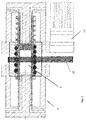
- FIG. 2 a reciprocating compressor according to the invention is shown, the structure of which is essentially the embodiment of Figure 1 corresponds to.
- the drive 18 is arranged outside the housing 7 with the ball screw drive and flanged to it.
- the rotary movement of the ball nut 10 is conveyed via a belt 19.
- the piston compressor according to the invention allows numerous variations.
- One side of the piston can be designed as a low-pressure system and the other side of the piston as a high-pressure system.
- Different media can be compressed at the same time in the compression rooms. For example, a liquid can be compressed on one side and a gas on the other.
- the piston compressor according to the invention enables the available working volume to be varied for one and the same device. It is not necessary to replace the entire device.
Priority Applications (1)
| Application Number | Priority Date | Filing Date | Title |
|---|---|---|---|
| PL14753070T PL3044461T3 (pl) | 2013-09-13 | 2014-08-19 | Sprężarka tłokowa |
Applications Claiming Priority (2)
| Application Number | Priority Date | Filing Date | Title |
|---|---|---|---|
| DE102013015142 | 2013-09-13 | ||
| PCT/EP2014/067652 WO2015036206A1 (de) | 2013-09-13 | 2014-08-19 | Kolbenverdichter |
Publications (2)
| Publication Number | Publication Date |
|---|---|
| EP3044461A1 EP3044461A1 (de) | 2016-07-20 |
| EP3044461B1 true EP3044461B1 (de) | 2021-04-21 |
Family
ID=51383723
Family Applications (1)
| Application Number | Title | Priority Date | Filing Date |
|---|---|---|---|
| EP14753070.3A Active EP3044461B1 (de) | 2013-09-13 | 2014-08-19 | Kolbenverdichter |
Country Status (5)
| Country | Link |
|---|---|
| EP (1) | EP3044461B1 (da) |
| DK (1) | DK3044461T3 (da) |
| ES (1) | ES2871415T3 (da) |
| PL (1) | PL3044461T3 (da) |
| WO (1) | WO2015036206A1 (da) |
Family Cites Families (4)
| Publication number | Priority date | Publication date | Assignee | Title |
|---|---|---|---|---|
| BE719392A (da) * | 1968-08-12 | 1969-02-12 | ||
| US6068448A (en) * | 1996-12-09 | 2000-05-30 | Sugino Machine Limited | Pressure hydraulic pump having first and second synchronously driven reciprocating pistons with a pressure control structure |
| US6398514B1 (en) * | 2000-11-22 | 2002-06-04 | Steve C. Smith | Double-acting rod pump |
| CA2514817A1 (en) * | 2005-08-11 | 2007-02-11 | Afif Abou-Raphael | Reciprocating double acting pump |
-
2014
- 2014-08-19 PL PL14753070T patent/PL3044461T3/pl unknown
- 2014-08-19 WO PCT/EP2014/067652 patent/WO2015036206A1/de active Application Filing
- 2014-08-19 DK DK14753070.3T patent/DK3044461T3/da active
- 2014-08-19 EP EP14753070.3A patent/EP3044461B1/de active Active
- 2014-08-19 ES ES14753070T patent/ES2871415T3/es active Active
Non-Patent Citations (1)
| Title |
|---|
| None * |
Also Published As
| Publication number | Publication date |
|---|---|
| WO2015036206A1 (de) | 2015-03-19 |
| PL3044461T3 (pl) | 2021-10-25 |
| DK3044461T3 (da) | 2021-07-12 |
| ES2871415T3 (es) | 2021-10-28 |
| EP3044461A1 (de) | 2016-07-20 |
Similar Documents
| Publication | Publication Date | Title |
|---|---|---|
| DE2529331C2 (de) | Schraubenkompressor | |
| DE2255866C3 (de) | Strangpresse | |
| DE2632748A1 (de) | Druckmittelbetaetigte schiebevorrichtung | |
| DE2645213B2 (de) | Schlagwerkzeug, insbesondere für Gesteinsbohrmaschinen | |
| EP0139709B1 (de) | Doppelwirkende hin-und hergehende kolbenpumpe | |
| DE1947641B2 (de) | Als Pumpe oder Motor ausgebildete Maschine veränderlicher Verdrängung | |
| DE1403973A1 (de) | Dosierungspumpe | |
| EP3044461B1 (de) | Kolbenverdichter | |
| EP0618025B1 (de) | Einpressaggregat | |
| DE2058278A1 (de) | Druckmittelbetaetigter Motor | |
| WO2002011969A1 (de) | Einspritzaggregat für eine kunststoffspritzgiessmaschine | |
| EP1526930A1 (de) | Haupt- bzw. presszylinder einer rohr- und strangpresse | |
| DE4326407C2 (de) | Hubkolben-Kältemittelverdichter mit ansaugseitigem Drehschieber | |
| DE1917116C3 (de) | Hydraulikzylinder mit Eilgang und Krafthub | |
| AT400941B (de) | Einrichtung zur versorgung von hydraulischen verbrauchern einer spritzgiessmaschine mit einer unter druck stehenden hydraulikflüssigkeit | |
| EP0536365B1 (de) | Pastenextruder | |
| EP3746637B1 (de) | Lamellenmotor | |
| DE2121006A1 (de) | Verfahren und Vorrichtung zum Portionieren, Einfüllen und Abdrehen einer pastenförmigen Masse in eine schlauchförmige Hülle | |
| DE2900281A1 (de) | Druckluftzylinder mit einer daempfungsvorrichtung | |
| AT526153B1 (de) | Antriebseinheit für eine Formgebungsmaschine | |
| DE1301252B (de) | Zylindereinheit mit Druckuebersetzung | |
| DE2434783A1 (de) | Schraubenverdichter sowie verfahren zum einspritzen einer fluessigkeit in denselben | |
| DE10051101B4 (de) | Einspritzschneckenantrieb für eine Kunststoffspritzgiessmaschine | |
| EP1379866A2 (de) | Prüfvorrichtung für die ultraschallprüfung von stangenmaterial | |
| DE1628382C3 (de) | AuBenachsiger Drehkolbenverdichter mit schraubverzahnten Rotoren und verstellbarem Abdeckschieber |
Legal Events
| Date | Code | Title | Description |
|---|---|---|---|
| PUAI | Public reference made under article 153(3) epc to a published international application that has entered the european phase |
Free format text: ORIGINAL CODE: 0009012 |
|
| 17P | Request for examination filed |
Effective date: 20160226 |
|
| AK | Designated contracting states |
Kind code of ref document: A1 Designated state(s): AL AT BE BG CH CY CZ DE DK EE ES FI FR GB GR HR HU IE IS IT LI LT LU LV MC MK MT NL NO PL PT RO RS SE SI SK SM TR |
|
| AX | Request for extension of the european patent |
Extension state: BA ME |
|
| DAX | Request for extension of the european patent (deleted) | ||
| STAA | Information on the status of an ep patent application or granted ep patent |
Free format text: STATUS: EXAMINATION IS IN PROGRESS |
|
| 17Q | First examination report despatched |
Effective date: 20171016 |
|
| REG | Reference to a national code |
Ref country code: DE Ref legal event code: R079 Ref document number: 502014015504 Country of ref document: DE Free format text: PREVIOUS MAIN CLASS: F04B0009020000 Ipc: F04B0035010000 |
|
| GRAP | Despatch of communication of intention to grant a patent |
Free format text: ORIGINAL CODE: EPIDOSNIGR1 |
|
| STAA | Information on the status of an ep patent application or granted ep patent |
Free format text: STATUS: GRANT OF PATENT IS INTENDED |
|
| RIC1 | Information provided on ipc code assigned before grant |
Ipc: F04B 35/01 20060101AFI20201126BHEP Ipc: F04B 39/06 20060101ALI20201126BHEP |
|
| INTG | Intention to grant announced |
Effective date: 20201211 |
|
| GRAS | Grant fee paid |
Free format text: ORIGINAL CODE: EPIDOSNIGR3 |
|
| GRAA | (expected) grant |
Free format text: ORIGINAL CODE: 0009210 |
|
| STAA | Information on the status of an ep patent application or granted ep patent |
Free format text: STATUS: THE PATENT HAS BEEN GRANTED |
|
| AK | Designated contracting states |
Kind code of ref document: B1 Designated state(s): AL AT BE BG CH CY CZ DE DK EE ES FI FR GB GR HR HU IE IS IT LI LT LU LV MC MK MT NL NO PL PT RO RS SE SI SK SM TR |
|
| REG | Reference to a national code |
Ref country code: GB Ref legal event code: FG4D Free format text: NOT ENGLISH |
|
| REG | Reference to a national code |
Ref country code: CH Ref legal event code: EP Ref country code: CH Ref legal event code: NV Representative=s name: KELLER SCHNEIDER PATENT- UND MARKENANWAELTE AG, CH |
|
| REG | Reference to a national code |
Ref country code: DE Ref legal event code: R096 Ref document number: 502014015504 Country of ref document: DE Ref country code: IE Ref legal event code: FG4D Free format text: LANGUAGE OF EP DOCUMENT: GERMAN Ref country code: NL Ref legal event code: FP |
|
| REG | Reference to a national code |
Ref country code: AT Ref legal event code: REF Ref document number: 1384908 Country of ref document: AT Kind code of ref document: T Effective date: 20210515 |
|
| REG | Reference to a national code |
Ref country code: DK Ref legal event code: T3 Effective date: 20210706 |
|
| REG | Reference to a national code |
Ref country code: LT Ref legal event code: MG9D |
|
| REG | Reference to a national code |
Ref country code: ES Ref legal event code: FG2A Ref document number: 2871415 Country of ref document: ES Kind code of ref document: T3 Effective date: 20211028 |
|
| PG25 | Lapsed in a contracting state [announced via postgrant information from national office to epo] |
Ref country code: LT Free format text: LAPSE BECAUSE OF FAILURE TO SUBMIT A TRANSLATION OF THE DESCRIPTION OR TO PAY THE FEE WITHIN THE PRESCRIBED TIME-LIMIT Effective date: 20210421 Ref country code: FI Free format text: LAPSE BECAUSE OF FAILURE TO SUBMIT A TRANSLATION OF THE DESCRIPTION OR TO PAY THE FEE WITHIN THE PRESCRIBED TIME-LIMIT Effective date: 20210421 Ref country code: BG Free format text: LAPSE BECAUSE OF FAILURE TO SUBMIT A TRANSLATION OF THE DESCRIPTION OR TO PAY THE FEE WITHIN THE PRESCRIBED TIME-LIMIT Effective date: 20210721 Ref country code: HR Free format text: LAPSE BECAUSE OF FAILURE TO SUBMIT A TRANSLATION OF THE DESCRIPTION OR TO PAY THE FEE WITHIN THE PRESCRIBED TIME-LIMIT Effective date: 20210421 |
|
| PG25 | Lapsed in a contracting state [announced via postgrant information from national office to epo] |
Ref country code: GR Free format text: LAPSE BECAUSE OF FAILURE TO SUBMIT A TRANSLATION OF THE DESCRIPTION OR TO PAY THE FEE WITHIN THE PRESCRIBED TIME-LIMIT Effective date: 20210722 Ref country code: LV Free format text: LAPSE BECAUSE OF FAILURE TO SUBMIT A TRANSLATION OF THE DESCRIPTION OR TO PAY THE FEE WITHIN THE PRESCRIBED TIME-LIMIT Effective date: 20210421 Ref country code: IS Free format text: LAPSE BECAUSE OF FAILURE TO SUBMIT A TRANSLATION OF THE DESCRIPTION OR TO PAY THE FEE WITHIN THE PRESCRIBED TIME-LIMIT Effective date: 20210821 Ref country code: PT Free format text: LAPSE BECAUSE OF FAILURE TO SUBMIT A TRANSLATION OF THE DESCRIPTION OR TO PAY THE FEE WITHIN THE PRESCRIBED TIME-LIMIT Effective date: 20210823 Ref country code: NO Free format text: LAPSE BECAUSE OF FAILURE TO SUBMIT A TRANSLATION OF THE DESCRIPTION OR TO PAY THE FEE WITHIN THE PRESCRIBED TIME-LIMIT Effective date: 20210721 Ref country code: RS Free format text: LAPSE BECAUSE OF FAILURE TO SUBMIT A TRANSLATION OF THE DESCRIPTION OR TO PAY THE FEE WITHIN THE PRESCRIBED TIME-LIMIT Effective date: 20210421 Ref country code: SE Free format text: LAPSE BECAUSE OF FAILURE TO SUBMIT A TRANSLATION OF THE DESCRIPTION OR TO PAY THE FEE WITHIN THE PRESCRIBED TIME-LIMIT Effective date: 20210421 |
|
| REG | Reference to a national code |
Ref country code: DE Ref legal event code: R097 Ref document number: 502014015504 Country of ref document: DE |
|
| PG25 | Lapsed in a contracting state [announced via postgrant information from national office to epo] |
Ref country code: RO Free format text: LAPSE BECAUSE OF FAILURE TO SUBMIT A TRANSLATION OF THE DESCRIPTION OR TO PAY THE FEE WITHIN THE PRESCRIBED TIME-LIMIT Effective date: 20210421 Ref country code: SK Free format text: LAPSE BECAUSE OF FAILURE TO SUBMIT A TRANSLATION OF THE DESCRIPTION OR TO PAY THE FEE WITHIN THE PRESCRIBED TIME-LIMIT Effective date: 20210421 Ref country code: SM Free format text: LAPSE BECAUSE OF FAILURE TO SUBMIT A TRANSLATION OF THE DESCRIPTION OR TO PAY THE FEE WITHIN THE PRESCRIBED TIME-LIMIT Effective date: 20210421 Ref country code: EE Free format text: LAPSE BECAUSE OF FAILURE TO SUBMIT A TRANSLATION OF THE DESCRIPTION OR TO PAY THE FEE WITHIN THE PRESCRIBED TIME-LIMIT Effective date: 20210421 |
|
| PLBE | No opposition filed within time limit |
Free format text: ORIGINAL CODE: 0009261 |
|
| STAA | Information on the status of an ep patent application or granted ep patent |
Free format text: STATUS: NO OPPOSITION FILED WITHIN TIME LIMIT |
|
| 26N | No opposition filed |
Effective date: 20220124 |
|
| PG25 | Lapsed in a contracting state [announced via postgrant information from national office to epo] |
Ref country code: MC Free format text: LAPSE BECAUSE OF FAILURE TO SUBMIT A TRANSLATION OF THE DESCRIPTION OR TO PAY THE FEE WITHIN THE PRESCRIBED TIME-LIMIT Effective date: 20210421 |
|
| REG | Reference to a national code |
Ref country code: BE Ref legal event code: MM Effective date: 20210831 |
|
| PG25 | Lapsed in a contracting state [announced via postgrant information from national office to epo] |
Ref country code: IS Free format text: LAPSE BECAUSE OF FAILURE TO SUBMIT A TRANSLATION OF THE DESCRIPTION OR TO PAY THE FEE WITHIN THE PRESCRIBED TIME-LIMIT Effective date: 20210821 Ref country code: LU Free format text: LAPSE BECAUSE OF NON-PAYMENT OF DUE FEES Effective date: 20210819 Ref country code: AL Free format text: LAPSE BECAUSE OF FAILURE TO SUBMIT A TRANSLATION OF THE DESCRIPTION OR TO PAY THE FEE WITHIN THE PRESCRIBED TIME-LIMIT Effective date: 20210421 |
|
| PG25 | Lapsed in a contracting state [announced via postgrant information from national office to epo] |
Ref country code: IE Free format text: LAPSE BECAUSE OF NON-PAYMENT OF DUE FEES Effective date: 20210819 Ref country code: BE Free format text: LAPSE BECAUSE OF NON-PAYMENT OF DUE FEES Effective date: 20210831 |
|
| PG25 | Lapsed in a contracting state [announced via postgrant information from national office to epo] |
Ref country code: HU Free format text: LAPSE BECAUSE OF FAILURE TO SUBMIT A TRANSLATION OF THE DESCRIPTION OR TO PAY THE FEE WITHIN THE PRESCRIBED TIME-LIMIT; INVALID AB INITIO Effective date: 20140819 |
|
| PG25 | Lapsed in a contracting state [announced via postgrant information from national office to epo] |
Ref country code: CY Free format text: LAPSE BECAUSE OF FAILURE TO SUBMIT A TRANSLATION OF THE DESCRIPTION OR TO PAY THE FEE WITHIN THE PRESCRIBED TIME-LIMIT Effective date: 20210421 |
|
| P01 | Opt-out of the competence of the unified patent court (upc) registered |
Effective date: 20230525 |
|
| PGFP | Annual fee paid to national office [announced via postgrant information from national office to epo] |
Ref country code: NL Payment date: 20230620 Year of fee payment: 10 Ref country code: FR Payment date: 20230525 Year of fee payment: 10 Ref country code: CZ Payment date: 20230529 Year of fee payment: 10 |
|
| PGFP | Annual fee paid to national office [announced via postgrant information from national office to epo] |
Ref country code: PL Payment date: 20230525 Year of fee payment: 10 |
|
| PGFP | Annual fee paid to national office [announced via postgrant information from national office to epo] |
Ref country code: IT Payment date: 20230823 Year of fee payment: 10 Ref country code: GB Payment date: 20230705 Year of fee payment: 10 Ref country code: ES Payment date: 20230906 Year of fee payment: 10 Ref country code: CH Payment date: 20230902 Year of fee payment: 10 Ref country code: AT Payment date: 20230831 Year of fee payment: 10 |
|
| PGFP | Annual fee paid to national office [announced via postgrant information from national office to epo] |
Ref country code: DK Payment date: 20230713 Year of fee payment: 10 Ref country code: DE Payment date: 20230830 Year of fee payment: 10 |
|
| PG25 | Lapsed in a contracting state [announced via postgrant information from national office to epo] |
Ref country code: MK Free format text: LAPSE BECAUSE OF FAILURE TO SUBMIT A TRANSLATION OF THE DESCRIPTION OR TO PAY THE FEE WITHIN THE PRESCRIBED TIME-LIMIT Effective date: 20210421 |