EP3044389B1 - Pfosten-riegel-konstruktion - Google Patents
Pfosten-riegel-konstruktion Download PDFInfo
- Publication number
- EP3044389B1 EP3044389B1 EP14771242.6A EP14771242A EP3044389B1 EP 3044389 B1 EP3044389 B1 EP 3044389B1 EP 14771242 A EP14771242 A EP 14771242A EP 3044389 B1 EP3044389 B1 EP 3044389B1
- Authority
- EP
- European Patent Office
- Prior art keywords
- insulating strip
- strip
- mullion
- insulating
- hollow chamber
- Prior art date
- Legal status (The legal status is an assumption and is not a legal conclusion. Google has not performed a legal analysis and makes no representation as to the accuracy of the status listed.)
- Active
Links
Images




Classifications
-
- E—FIXED CONSTRUCTIONS
- E04—BUILDING
- E04B—GENERAL BUILDING CONSTRUCTIONS; WALLS, e.g. PARTITIONS; ROOFS; FLOORS; CEILINGS; INSULATION OR OTHER PROTECTION OF BUILDINGS
- E04B2/00—Walls, e.g. partitions, for buildings; Wall construction with regard to insulation; Connections specially adapted to walls
- E04B2/88—Curtain walls
- E04B2/96—Curtain walls comprising panels attached to the structure through mullions or transoms
- E04B2/965—Connections of mullions and transoms
-
- E—FIXED CONSTRUCTIONS
- E04—BUILDING
- E04B—GENERAL BUILDING CONSTRUCTIONS; WALLS, e.g. PARTITIONS; ROOFS; FLOORS; CEILINGS; INSULATION OR OTHER PROTECTION OF BUILDINGS
- E04B1/00—Constructions in general; Structures which are not restricted either to walls, e.g. partitions, or floors or ceilings or roofs
- E04B1/62—Insulation or other protection; Elements or use of specified material therefor
- E04B1/74—Heat, sound or noise insulation, absorption, or reflection; Other building methods affording favourable thermal or acoustical conditions, e.g. accumulating of heat within walls
- E04B1/76—Heat, sound or noise insulation, absorption, or reflection; Other building methods affording favourable thermal or acoustical conditions, e.g. accumulating of heat within walls specifically with respect to heat only
- E04B1/7608—Heat, sound or noise insulation, absorption, or reflection; Other building methods affording favourable thermal or acoustical conditions, e.g. accumulating of heat within walls specifically with respect to heat only comprising a prefabricated insulating layer, disposed between two other layers or panels
- E04B1/7612—Heat, sound or noise insulation, absorption, or reflection; Other building methods affording favourable thermal or acoustical conditions, e.g. accumulating of heat within walls specifically with respect to heat only comprising a prefabricated insulating layer, disposed between two other layers or panels in combination with an air space
-
- E—FIXED CONSTRUCTIONS
- E04—BUILDING
- E04B—GENERAL BUILDING CONSTRUCTIONS; WALLS, e.g. PARTITIONS; ROOFS; FLOORS; CEILINGS; INSULATION OR OTHER PROTECTION OF BUILDINGS
- E04B2/00—Walls, e.g. partitions, for buildings; Wall construction with regard to insulation; Connections specially adapted to walls
- E04B2/88—Curtain walls
- E04B2/96—Curtain walls comprising panels attached to the structure through mullions or transoms
- E04B2/967—Details of the cross-section of the mullions or transoms
-
- E—FIXED CONSTRUCTIONS
- E04—BUILDING
- E04D—ROOF COVERINGS; SKY-LIGHTS; GUTTERS; ROOF-WORKING TOOLS
- E04D13/00—Special arrangements or devices in connection with roof coverings; Protection against birds; Roof drainage ; Sky-lights
- E04D13/03—Sky-lights; Domes; Ventilating sky-lights
- E04D13/0305—Supports or connecting means for sky-lights of flat or domed shape
Definitions
- the present invention relates to a mullion and transom construction, in particular for facades or light roofs, according to the preamble of claim 1.
- the EP 1 352 134 discloses a mullion and transom construction in which a screw groove is formed on the mullion between two panes of glass.
- a screw groove is formed on the mullion between two panes of glass.
- an insulating profile is inserted, which has a hollow chamber.
- several screws for fixing the glass panes can be mounted on a pressure bar.
- the arrangement of such an insulating profile on the screw has proven itself, but the thermal insulation is limited, because the insulating usually consists of a harder plastic, which has a comparatively high heat conduction.
- the thermal insulation due to the closed design of the hollow chamber of the insulating profile can not be adjusted.
- the EP 1 596 022 A2 discloses a pressure strip for a post or latch, in which an insulating strip and a sealing strip are formed integrally with the pressure strip.
- the mullion-transom construction of EP 1 596 022 A2 discloses all features of the preamble of claim 1.
- the DE 203 19 978 U1 discloses a facade in which an insulating block is provided with a filled hollow chamber between two filling elements.
- the insulating strip comprises at one end face of a filling element a hollow chamber, which can be closed by at least one movable cover, so that access to the hollow chamber is made possible via the cover.
- a hollow chamber which can be closed by at least one movable cover, so that access to the hollow chamber is made possible via the cover.
- the hollow chamber can then be inserted as needed Dämm advisorn or other elements, which allows flexible adaptation of the insulating strip.
- cover is intended to include any element that can provide access to the hollow chamber, regardless whether the cover is pivotable or displaceable or otherwise provides access.
- the cover is latched to the insulating strip.
- the insulating strip comprises at least one film hinge, on which the cover is pivotally mounted. It is possible that the insulating strip is formed of two parts, in which case a part forms the cover and is pivotally supported by the film hinge. It is also possible to pivotally hold the cover over two or more juxtaposed film hinges so that particularly wide opening angles can be realized.
- a material is at least partially inserted into the hollow chamber, which has a higher thermal insulation than a molded body of the insulating strip.
- the materials may in particular be formed from an insulating foam or other insulating material, which is formed for example from polyethylene, polypropylene, polyurethane, polyisocyanurate, polystyrene, phenolic resin and / or mineral wool.
- insulating materials it is possible to use all materials which have an effect with regard to heat insulation, sound insulation, fire protection or combinations of these functions.
- the insulating strip has a molded body, on the outside at least partially an insulating strip is set with higher thermal insulation than the molded body.
- the above-mentioned insulating materials in particular of an insulating foam, can be used.
- the insulating strip may have a shaped body having a plurality of openings in the longitudinal direction.
- the molded body of the insulating strip usually consists of a dimensionally stable plastic body, which has a comparatively high thermal conductivity.
- the molding made of plastic molding of the insulating strip may preferably be formed thin-walled to ensure good thermal insulation.
- the wall thickness of the shaped body can be in a range between 0.3 mm to 1.6 mm, in particular 0.5 mm to 1.3 mm.
- the hollow chamber of the insulating strip can be divided by at least one partition. Through the partition wall and the stability of the molding can be increased.
- an insulating element is inserted as a molded body in the hollow chamber.
- the insulating element can be inserted as a loose strip. It is also possible to foam a Dämmst adopted in the hollow chamber, for example by coextrusion.
- a bottom of a groove of the insulating strip on a film hinge by means of which the insulating strip is pivotable in two halves.
- the insulating strip is formed closed in the assembled state on the outside, so that when screwing a screw into the groove and a screw groove arranged behind the insulating strip is not accidentally opened.
- a post-and-beam construction comprises a support profile 1, which may be designed as a post or bolt, wherein a screw groove 2 is provided on an outer side. On both sides of the screw 2 holder 3 are formed for sealing strips 4, the edge of a filling element 5, in particular an insulating glass, abut.
- a pressure strip 7 is provided, which is arranged with seals 8 on an outer side of the filling elements 5.
- the filling elements 5 are each clamped edge between the seals 8 and 4 sealing strips.
- the pressure bar 7 is fixed by a plurality of screws 11 which are arranged in a gap 6 between the end faces of the filling elements 5 and engage in the screw groove 2.
- an insulating strip 10 is further provided, which is penetrated by the screw 11 and has a shaped body 12, on the outside of an insulating strip 13 made of a material with high thermal insulation; for example, a foamed DämmstMail arranged.
- the insulating strip 13 has a plurality of sealing lips 14 which abut against an end face of the filling elements 5.
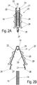
- an insulating profile 20 which has a shaped body 21 made of a harder plastic, for example PVC, which encloses a hollow chamber 22.
- a groove 23 is formed which is surrounded by lateral webs 24 and serves for example for fixing a seal or another component.
- the bottom of the groove 23 is formed as a V-shaped film hinge 25, so that the two halves of the shaped body 21 can be pivoted about the film hinge 25 to provide access to the hollow chamber 22.
- insulating strips 28 are provided which have a plurality of outwardly projecting sealing projections 29 and sealing lips.
- the material of the insulating strips 28 consists of a material of higher thermal insulation than the molded body 21, for example, an insulating foam.
- a male member 26 is formed on the molded body 21, on which a latching device 27 is provided.
- the two halves of the molded body 21 can be pivoted about the film hinge 25, so that the hollow chamber 22 can be opened on the male member 26.
- a molded part 15 are inserted with high thermal insulation, for example of a foamed material, in particular a damping material of polyethylene, polypropylene, polyurethane, polyisocyanurate, polystyrene, phenolic resin or mineral wool.
- This molding 15 of insulating material can take over functions in terms of heat protection, sound insulation and fire protection.
- the molded part 15 has in the middle region two grooves 16, engage in the webs 32 on the mold part 21, so that the molded part is fixed within the hollow chamber 22.
- a molded part 15 is inserted into the hollow chamber 22 for a higher thermal insulation and from which material the molded part 15 is selected. This results in a high degree of flexibility with regard to the intended use of the insulating strip 20.
- the molded body 21 of the insulating strip 20 can be pivoted about the film hinge 25 until the latching device 27 latches and the insulating strip 20 now
- the post-and-beam construction can be mounted as shown in, for example FIG. 1 is shown.
- FIGS. 3A to 3C a modified embodiment of an insulating strip is shown, in which not only a single molded part 15 can be inserted into the hollow chamber 22 of the molded body 21, but two mold parts 17 and 18.
- the mold parts 17 and 18 may be made of the same or a different material. In this case, each mold part 17 or 18 may be loosely inserted or glued into the hollow chamber 22. Between the mold parts 17 and 18, the webs 32 can be used as a spacer.
- the insulating strip as in the previous embodiment of FIG. 2 educated.
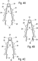
- FIGS. 4A to 4C is the insulating strip of FIG. 2 shown with modified locking mechanisms.
- FIG. 4A is on the male member 26 a Druccknopf 34 is formed, which locks when squeezing the snap fastener parts.
- FIG. 4B is on the male member 26, a latching device with locking recesses 35 and locking webs 36 are provided, which are each arranged on the inside of the male member 26 and lock together upon compression of the male member.
- a latching device with locking recesses 35 and locking webs 36 are provided, which are each arranged on the inside of the male member 26 and lock together upon compression of the male member.
- three locking receptacles 35 and three locking webs 36 are provided, so that when damaging a latching connection, the remaining latching connections keep the shaped body 21 in the latched position.
- FIG. 4C a latching device with a latching receptacle 37 and a latching web 38 is formed.
- integrally formed latching devices can be provided, which can be designed as pushbuttons, undercut contours, snap-in webs, snap connections or other types of snap connections.
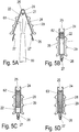
- FIGS. 5A to 5D a further embodiment of an insulating strip is shown according to FIG. 5A initially shown in an open position.
- the insulating strip corresponds to the embodiment of the FIG. 2B
- a foaming material 61 is injected into the hollow chamber 22.
- the insulating strip is closed, as in FIG. 5B is shown, wherein the latching device 27 provides on the male member 26 for fixing the insulating member in the closed position.
- the foamed material 62 can now fill the hollow chamber 22 in whole or in part, if necessary, wherein in FIG.
- FIG. 5B only a slight expansion of the foaming material 62 is present.
- the material can also foam further and occupy a larger volume, as in FIG. 5C is shown, in which the material 62 'already extends over more than 2/3 of the volume of the hollow chamber 22. Further, it is possible to add the intumescent material with a volume that completely fills the hollow chamber 22, as shown in FIG. 5D is shown.
- FIG. 6 is a further embodiment of an insulating strip shown in the structure of in FIG. 2 shown insulating strip, however, two strips with circular openings 80 are additionally provided in the side walls of the insulating strip.
- the openings 80 may also have a geometry other than circular, for example, square, rectangular, triangular or another contour.
- the apertures 80 are arranged in strips in the longitudinal direction of the insulating strip, wherein the surface of the apertures 80 based on the surface of the strip at least 50%, preferably about 70%, in particular more than 80%, occupies, wherein the corresponding geometric strip has a width, which corresponds to the width of the openings 80.
- FIG. 6 are two strips provided with openings 80, which are arranged on opposite sides of the insulating strip. It is also possible to provide only one strip with openings 80 or more than two strips with openings 80.
- the material of the molded body 21 is recessed, so that the heat conduction is reduced, because by reducing the cross-section of the shaped body 21 of the male member 26 to the groove 23 toward is in the mullion-transom construction of FIG. 1 from outside to inside reduces the heat conduction.
- FIG. 7A is a section through the insulating strip of FIG. 6 shown, wherein it can be seen that the inserted into the hollow chamber 22 molded part 15 is not formed broken through, but the hollow chamber 22 is filled.
- the openings 80 extend only through the outer DämmstMail 28 and the molded body 21st
- FIG. 7B It is also possible to provide the perforations 80 in such a way that the complete insulating strip is broken, that is to say both in the region of the insulating strip 28, in the region of the molded article 21 and in the region of the molded article 15 of heat-insulating material. This facilitates the production of the insulating strip, even if the thermal insulation is slightly deteriorated.
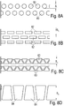
- FIG. 8A are the openings 80 in the mold body 21 according to FIG. 6 shown schematically.
- the openings 80 are arranged in the longitudinal direction of the insulating strip at regular intervals and extend parallel to the longitudinal direction strip-shaped.
- the width of a strip S 1 corresponds to the width of the openings 80. Based on the width of the strip S 1 , the openings 80 occupy an area of at least 50%, preferably at least 70%.
- Openings 82 are shown in a rectangular shape, which have a smaller width S 2 than the circular openings 80. Instead of two strips three parallel strips with openings 82 are provided.
- triangular openings 83 are provided, so that a truss-like structure is provided in the profile body 21.
- the triangles are alternately aligned with a tip up or a tip down, so that obliquely extending webs are formed therebetween.
- the openings 83 in triangular shape are aligned in a strip parallel to the longitudinal direction, wherein based on the width of the strip S 3, the area of the openings occupies at least 80% of the surface of the strip.
- the openings 84 are trapezoidal and have a parallel to the longitudinal direction of the insulating strip extending longer base edge and shorter end edge.
- the trapezoidal openings 84 are each arranged alternately rotated by 180 °, so that seen in the longitudinal direction alternately a longer base edge to a shorter end edge is present. Based on the width S 4 of the strip with the openings 84, the apertures occupy at least 85% of the area.
- the apertures 80, 82, 83, and 84 may also have other geometric shapes, and the number of strips with openings can be chosen freely depending on the size of the profile body 21 and the openings.
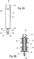
- FIG 9A a further embodiment of a molded body made of a plastic for an insulating strip is shown.
- the molded body comprises a hollow chamber 22 of substantially rectangular design in cross-section for the optional insertion of an insulating material.
- a groove 23 is formed, which is surrounded by lateral webs 24, which have inwardly directed projections and can be used to define a seal or other component.
- the bottom of the groove 23 is formed as a V-shaped film hinge 25, so that the two halves of the shaped body 21 can be pivoted about the film hinge 25 to provide access to the hollow chamber 22.
- a male member 26 is formed, which is formed of two spaced wall portions surrounding the hollow chambers 94 and 95.
- the wall portions of the male member 26 are fixed via locking webs 90, 91 and 92, 93, which are hook-shaped and fix the closed position of the molding.
- the two halves of the shaped body 21 can be pivoted about the film hinge 25. It is additionally or alternatively possible to open the hollow chamber 22, in which one side of the molded body 21 is pivoted about a further film hinge 96 which is formed on a side wall of the hollow chamber 22 adjacent to the groove 23.
- a further film hinge 96 which is formed on a side wall of the hollow chamber 22 adjacent to the groove 23.
- the film hinge 96 can also be provided on opposite sides of the hollow chamber 22, instead of only on one side.
- FIG. 9B the insulating strip is shown with the molding of Figure 14A, in which in the hollow chamber 22 in which a strip-shaped molding 15 is inserted loosely with high thermal insulation.
- insulating strips 97 are fixed, in particular by gluing.
- the described embodiments can be combined with each other arbitrarily, for example, instead of a single hollow chamber, a plurality of hollow chambers can be provided on the insulating strip.
- you can one or more of the hollow chambers are filled with moldings of heat-insulating material, wherein the material of the moldings can be used depending on the desired function. Insbesondre it may be necessary for reasons of fire protection, use only certain insulation materials, while for optimal thermal insulation other materials are preferred.
- the mold parts 15 may be mechanically fixed in the hollow chamber as well as glued or foamed.
Landscapes
- Engineering & Computer Science (AREA)
- Architecture (AREA)
- Physics & Mathematics (AREA)
- Civil Engineering (AREA)
- Structural Engineering (AREA)
- Electromagnetism (AREA)
- Acoustics & Sound (AREA)
- Building Environments (AREA)
Description
- Die vorliegende Erfindung betrifft eine Pfosten-Riegel-Konstruktion, insbesondere für Fassaden oder Lichtdächer,nach dem Oberbegriff des Anspruches 1.
- Die
EP 1 352 134 offenbart eine Pfosten-Riegel-Konstruktion, bei der zwischen zwei Glasscheiben eine Schraubnut an dem Pfostenprofil ausgebildet ist. In die Schraubnut ist ein Isolierprofil eingesteckt, das eine Hohlkammer aufweist. In das Isolierprofil und die Schraubnut können mehrere Schrauben zur Festlegung der Glasscheiben über eine Andruckleiste montiert werden. Die Anordnung eines solchen Isolierprofils an der Schraubnut hat sich an sich bewährt, allerdings ist die Wärmedämmung begrenzt, denn das Isolierprofil besteht meist aus einem härteren Kunststoff, der eine vergleichsweise hohe Wärmeleitung besitzt. Zudem kann die Wärmedämmung aufgrund der geschlossenen Ausbildung der Hohlkammer des Isolierprofils nicht angepasst werden. - Die
EP 1 596 022 A2 offenbart eine Andruckleiste für einen Pfosten oder Riegel, bei der eine Dämmleiste und eine Dichtleiste einstückig mit der Andruckleiste ausgebildet sind. Die Pfosten-Riegel-Konstruktion vonEP 1 596 022 A2 offenbart alle Merkmale des Oberbegriffs des Anspruchs 1. - Die
DE 203 19 978 U1 offenbart eine Fassade, bei der zwischen zwei Füllungselementen ein Dämmblock mit einer gefüllten Hohlkammer vorgesehen ist. - Es ist daher Aufgabe der vorliegenden Erfindung, eine Pfosten-Riegel-Konstruktion zu schaffen, die eine verbesserte Wärmedämmung aufweist und eine flexible Anpassung der Dämmeigenschaften ermöglicht.
- Diese Aufgabe wird mit einer Pfosten-Riegel-Konstruktion mit den Merkmalen des Anspruches 1 gelöst.
- Erfindungsgemäß umfasst die Isolierleiste an einer Stirnseite eines Füllungselementes eine Hohlkammer, die über mindestens eine bewegbare Abdeckung verschließbar ist, so dass über die Abdeckung ein Zugang zu der Hohlkammer ermöglicht wird. In die Hohlkammer können dann je nach Bedarf Dämmleisten oder andere Elemente eingefügt werden, was eine flexible Anpassung der Isolierleiste ermöglicht. Der Begriff der "Abdeckung" soll dabei jedes Element umfassen, das einen Zugang zu der Hohlkammer möglichen kann, unabhängig davon, ob die Abdeckung verschwenkbar oder verschiebbar ist oder auf sonstige Weise einen Zugang schafft.
- Die Abdeckung ist an der Isolierleiste verrastet. Vorzugsweise umfasst die Isolierleiste mindestens ein Filmscharnier, an dem die Abdeckung verschwenkbar gelagert ist. Es ist dabei möglich, dass die Isolierleiste aus zwei Teilen gebildet ist, wobei dann ein Teil die Abdeckung bildet und über das Filmscharnier verschwenkbar gehalten ist. Es ist auch möglich, die Abdeckung über zwei oder mehr benachbart angeordnete Filmscharniere verschwenkbar zu halten, so dass besonders weite Öffnungswinkel realisiert werden können.
- Erfindungsgemäß ist in die Hohlkammer zumindest teilweise ein Material eingefügt, das eine höhere Wärmedämmung besitzt als ein Formkörper der Isolierleiste. Die Materialien können insbesondere aus einem Dämmschaum oder einem andere Dämmmaterial gebildet sein, das beispielsweise aus Polyethylen, Polypropylen, Polyurethan, Polyisocyanurat, Polystyrol, Phenolharz und/oder Mineralwolle gebildet ist. Als Dämmmaterialien können sämtliche Materialien eingesetzt werden, die eine Wirkung im Hinblick auf einen Wärmeschutz, Schallschutz, Brandschutz oder Kombinationen dieser Funktionen aufweisen.
- Zusätzlich ist es möglich, dass die Isolierleiste einen Formkörper aufweist, an dessen Außenseite zumindest bereichsweise eine Dämmleiste mit höherer Wärmedämmung als der Formkörper festgelegt ist. Auch für die an der Außenseite angeordneten Dämmleisten an den Isolierleisten können die oben genannten Dämmmaterialien, insbesondere aus einem Dämmschaum, eingesetzt werden.
- Für eine besonders hohe Wärmedämmung kann die Isolierleiste einen Formkörper aufweisen, der in Längsrichtung eine Vielzahl von Durchbrechungen aufweist. Der Formkörper der Isolierleiste besteht meist aus einem formstabilen Kunststoffkörper, der eine vergleichsweise hohe Wärmeleitfähigkeit besitzt. Durch Reduzierung der Querschnittsfläche des Formkörpers durch die Durchbrechungen wird der Wärmefluss reduziert, wobei die Durchbrechungen hierfür in mindestens einem Streifen in Längsrichtung angeordnet sein können. An diesem Streifen kann die Fläche der Durchbrechungen mehr als 50 %, insbesondere mehr als 70 %, einnehmen.
- Der aus Kunststoff hergestellte Formkörper der Isolierleiste kann vorzugsweise dünnwandig ausgebildet sein, um eine gute Wärmeisolierung zu gewährleisten. Die Wandstärke des Formkörpers kann in einem Bereich zwischen 0,3mm bis 1,6mm, insbesondere 0,5mm bis 1,3mm liegen.
- Für eine weitere Erhöhung der Dämmung kann die Hohlkammer der Isolierleiste durch mindestens eine Trennwand unterteilt sein. Durch die Trennwand kann auch die Stabilität des Formkörpers erhöht werden.
- Vorzugsweise ist in die Hohlkammer ein Dämmelement als Formkörper eingefügt. Das Dämmelement kann als loser Streifen eingelegt sein. Es ist auch möglich, einen Dämmstreifen in die Hohlkammer einzuschäumen, beispielsweise durch Koextrusion.
- In einer bevorzugten Ausgestaltung weist ein Boden einer Nut der Isolierleiste ein Filmscharnier auf, mittels dem die Isolierleiste in zwei Hälften verschwenkbar ist. Dadurch ist die Isolierleiste im montierten Zustand an der Außenseite geschlossen ausgebildet, so dass beim Eindrehen einer Schraube in die Nut und eine dahinter angeordnete Schraubnut die die Isolierleiste nicht versehentlich geöffnet wird. Es sind daher Rastmittel zum Fixieren des Formkörpers in der geschlossenen Position an einem Einsteckteil ausgebildet, das in eine Schraubnut eingesteckt wird.
- Die Erfindung wird nachfolgend anhand mehrerer Ausführungsbeispiele mit Bezug auf die beigefügten Zeichnungen näher erläutert. Es zeigen:
- Figur 1
- eine Schnittansicht durch eine erfindungsgemäße Pfosten-Riegel-Konstruktion mit einer Isolierleiste;
- Figuren 2A und 2B
- zwei Ansichten einer Isolierleiste für eine erfindungsgemäße Pfosten-Riegel-Konstruktion;
- Figuren 3A bis 3C
- mehrere Ansichten einer zweiten isolierleiste;
- Figuren 4A bis 4C
- mehrere Ausführungsformen eines Rastmechanismus für eine Isolierleiste;
- Figuren 5A bis 5D
- mehrere Ansichten einer weiteren Isolierleiste mit einem eingeschäumten Dämmelement bei der Herstellung;
- Figur 6
- eine perspektivische Ansicht einer weiteren Ausführungsform einer Isolierleiste;
- Figuren 7A und 7B
- zwei Ansichten der Isolierleiste der
Figur 6 mit unterschiedlichen Durchbrechungen; - Figuren 8A bis 8D
- mehrere Ansichten von Durchbrechungen mit unterschiedlichen Geometrien, und
- Figur 9
- zwei Ansichten einer weiteren Ausführungsform einer Isolierleiste.
- Eine Pfosten-Riegel-Konstruktion umfasst ein Tragprofil 1, das als Pfosten oder Riegel ausgebildet sein kann, wobei an einer Außenseite eine Schraubnut 2 vorgesehen ist. Auf beiden Seiten der Schraubnut 2 sind Halter 3 für Dichtleisten 4 ausgebildet, die randseitig an einem Füllungselement 5, insbesondere einer Isolierglasscheibe, anliegen. Um das Füllungselement 5 festzulegen, ist eine Andruckleiste 7 vorgesehen, die mit Dichtungen 8 an einer Außenseite der Füllungselemente 5 angeordnet ist. Die Füllungselemente 5 werden jeweils zwischen den Dichtungen 8 und Dichtleisten 4 randseitig eingeklemmt. Die Andruckleiste 7 ist dabei über mehrere Schrauben 11 fixiert, die in einen Zwischenraum 6 zwischen den Stirnseiten der Füllungselemente 5 angeordnet sind und in die Schraubnut 2 eingreifen.
- An der Stirnseite eines Füllungselementes 5 ist ferner eine Isolierleiste 10 vorgesehen, die von der Schraube 11 durchgriffen ist und einen Formkörper 12 aufweist, an dessen Außenseite ein Dämmstreifen 13 aus einem Material mit hoher Wärmedämmung; beispielsweise einem geschäumten Dämmstreifen, angeordnet ist. Der Dämmstreifen 13 weist mehrere Dichtlippen 14 auf, die an einer Stirnseite der Füllungselemente 5 anliegen.
- Nachfolgend sollen unterschiedliche Ausgestaltungen einer solchen Isolierleiste 10 näher beschrieben werden, wobei gleiche Bauteile mit den gleichen Bezugszeichen versehen sind.
- In den
Figuren 2A und 2B ist ein Isolierprofil 20 gezeigt, das einen Formkörper 21 aus einem härteren Kunststoff, beispielsweise PVC, aufweist, der eine Hohlkammer 22 umschließt. Auf einer Seite des Isolierprofils 20 ist eine Nut 23 ausgebildet, die von seitlichen Stegen 24 umgeben ist und beispielsweise zur Festlegung einer Dichtung oder eines anderen Bauteils dient. Der Boden der Nut 23 ist als V-förmiges Filmscharnier 25 ausgebildet, so dass die beiden Hälften des Formkörpers 21 um das Filmscharnier 25 geschwenkt werden können, um einen Zugang zu der Hohlkammer 22 zu schaffen. - An zwei gegenüberliegenden Seitenflächen des Formkörpers 21 sind Dämmstreifen 28 vorgesehen, die mehrere nach außen hervorstehende Dichtvorsprünge 29 bzw. Dichtlippen aufweisen. Das Material der Dämmstreifen 28 besteht aus einem Material höherer Wärmedämmung als der Formkörper 21, beispielsweise aus einem Dämmschaum.
- Auf der zu der Nut 23 gegenüberliegenden Seite ist ein Einsteckelement 26 an dem Formkörper 21 ausgebildet, an dem eine Rasteinrichtung 27 vorgesehen ist. Wie in
Figur 2B gezeigt ist, können die zwei Hälften des Formkörpers 21 um das Filmscharnier 25 geschwenkt werden, so dass die Hohlkammer 22 an dem Einsteckelement 26 geöffnet werden kann. In dieser Position kann in die Hohlkammer 22 ein Formteil 15 mit hoher Wärmedämmung eingefügt werden, beispielsweise aus einem geschäumten Material, insbesondere einem Dämmmaterial aus Polyethylen, Polypropylen, Polyurethan, Polyisocyanurat, Polystyrol, Phenolharz oder Mineralwolle. Dieses Formteil 15 aus Dämmmaterial kann Funktionen hinsichtlich des Wärmeschutzes, des Schallschutzes und auch des Brandschutzes übernehmen. Das Formteil 15 weist im mittleren Bereich zwei Nuten 16 auf, in die Stege 32 an dem Formteil 21 eingreifen, so dass das Formteil innerhalb der Hohlkammer 22 fixiert ist. - Bei der Montage kann daher entschieden werden, ob ein Formteil 15 in die Hohlkammer 22 für eine höhere Wärmedämmung eingefügt wird und aus welchem Material das Formteil 15 ausgewählt wird. Dadurch ergibt sich ein hohes Maß an Flexibilität hinsichtlich des Einsatzzweckes der Isolierleiste 20. Nach dem Einfügen des Formteils 15 in die Hohlkammer 22 kann der Formkörper 21 der Isolierleiste 20 um das Filmscharnier 25 geschwenkt werden, bis die Rasteinrichtung 27 verrastet und die Isolierleiste 20 nun an der Pfosten-Riegel-Konstruktion montiert werden kann, wie sie beispielsweise in
Figur 1 gezeigt ist. - In den
Figuren 3A bis 3C ist eine modifizierte Ausgestaltung einer Isolierleiste gezeigt, bei der in die Hohlkammer 22 des Formkörpers 21 nicht nur ein einziges Formteil 15 eingefügt werden kann, sondern zwei Formteile 17 und 18. Die Formteile 17 und 18 können aus dem gleichen oder einem unterschiedlichen Material hergestellt sein. Dabei kann jedes Formteil 17 bzw. 18 in die Hohlkammer 22 lose eingefügt oder eingeklebt sein. Zwischen den Formteilen 17 und 18 können die Stege 32 als Abstandshalter genutzt werden. Im Übrigen ist die Isolierleiste wie bei dem vorangegangenen Ausführungsbeispiel derFigur 2 ausgebildet. - In den
Figuren 4A bis 4C ist die Isolierleiste derFigur 2 mit modifizierten Rastmechanismen gezeigt. InFigur 4A ist an dem Einsteckelement 26 ein Druccknopf 34 ausgebildet, der beim Zusammendrücken der Druckknopfteile verrastet. - In
Figur 4B ist an dem Einsteckelement 26 eine Rasteinrichtung mit Rastaufnahmen 35 und Raststegen 36 vorgesehen, die jeweils an der Innenseite des Einsteckelementes 26 angeordnet sind und beim Zusammendrücken des Einsteckelementes aneinander verrasten. Dabei sind drei Rastaufnahmen 35 und drei Raststege 36 vorgesehen, so dass bei Beschädigung einer Rastverbindung die übrigen Rastverbindungen den Formkörper 21 in der verrasteten Position halten. - In
Figur 4C ist eine Rasteinrichtung mit einer Rastaufnahme 37 und einem Raststeg 38 ausgebildet. - Für das Verrasten des Formkörpers 21 können integral ausgebildete Rasteinrichtungen vorgesehen sein, die als Druckknöpfe, Hinterschnittkonturen, Raststege, Schnappverbindungen oder andere Arten von Schnappverbindungen ausgebildet sein können.
- In den
Figuren 5A bis 5D ist eine weitere Ausführungsform einer Isolierleiste gezeigt, die entsprechendFigur 5A zunächst in einer geöffneten Position dargestellt ist. Die Isolierleiste entspricht dabei der Ausführungsform derFigur 2B , allerdings wird kein loses Formteil aus einem Dämmmaterial in die Hohlkammer 22 eingefügt, sondern über eine Düse 60 wird ein aufschäumendes Material 61 in die Hohlkammer 22 eingespritzt. Nach dem Einfügen des aufschäumenden Materials 61 wird die Isolierleiste geschlossen, wie dies inFigur 5B dargestellt ist, wobei die Rasteinrichtung 27 an dem Einsteckelement 26 für eine Fixierung des Isolierelementes in der geschlossenen Position sorgt. In dieser Position kann nun das eingeschäumte Material 62 bei Bedarf die Hohlkammer 22 ganz oder teilweise ausfüllen, wobei inFigur 5B nur eine geringfügige Ausdehnung des aufschäumenden Materials 62 vorhanden ist. Das Material kann auch noch weiter aufschäumen und ein größeres Volumen einnehmen, wie dies inFigur 5C gezeigt ist, bei dem sich das Material 62' schon über mehr als 2/3 des Volumens der Hohlkammer 22 erstreckt. Ferner ist es möglich, das aufschäumende Material mit einem Volumen hinzuzugeben, das die Hohlkammer 22 vollständig ausfüllt, wie dies inFigur 5D dargestellt ist. - In
Figur 6 ist ein weiteres Ausführungsbeispiel einer Isolierleiste gezeigt, die im Aufbau der inFigur 2 gezeigten Isolierleiste entspricht, allerdings sind zusätzlich in die Seitenwände der Isolierleiste zwei Streifen mit kreisförmigen Durchbrechungen 80 vorgesehen. Die Durchbrechungen 80 können auch eine andere Geometrie als kreisförmig besitzen, beispielsweise quadratisch, rechteckförmig, dreieckförmig oder eine andere Kontur. Die Durchbrechungen 80 sind in Streifen in Längsrichtung der Isolierleiste angeordnet, wobei die Fläche der Durchbrechungen 80 bezogen auf die Fläche des Streifens mindestens 50 %, vorzugsweise etwa 70 %, insbesondere mehr als 80 %, einnimmt, wobei der entsprechende geometrische Streifen eine Breite besitzt, die der Breite der Durchbrechungen 80 entspricht. InFigur 6 sind dabei zwei Streifen mit Durchbrechungen 80 vorgesehen, die an gegenüberliegenden Seiten der Isolierleiste angeordnet sind. Es ist auch möglich, nur einen Streifen mit Durchbrechungen 80 oder mehr als zwei Streifen mit Durchbrechungen 80 vorzusehen. - Durch die Durchbrechungen 80 wird das Material des Formkörpers 21 ausgespart, so dass die Wärmeleitung herabgesetzt wird, denn durch die Verminderung des Querschnittes des Formkörpers 21 von dem Einsteckelement 26 zu der Nut 23 hin wird bei der Pfosten-Riegel-Konstruktion der
Figur 1 von außen nach innen die Wärmeleitung vermindert. - In
Figur 7A ist ein Schnitt durch die Isolierleiste derFigur 6 gezeigt, wobei erkennbar ist, dass das in die Hohlkammer 22 eingefügte Formteil 15 nicht durchbrochen ausgebildet ist, sondern die Hohlkammer 22 ausgefüllt ist. Die Durchbrechungen 80 erstrecken sich lediglich durch den äußeren Dämmstreifen 28 und den Formkörper 21. - Alternativ ist es entsprechend
Figur 7B auch möglich, die Durchbrechungen 80 so vorzusehen, dass die komplette Isolierleiste durchbrochen wird, also sowohl im Bereich des Dämmstreifens 28, im Bereich des Formkörpers 21 und im Bereich des Formteils 15 aus wärmedämmendem Material. Dies erleichtert die Herstellung der Isolierleiste, auch wenn die Wärmedämmung geringfügig verschlechtert wird. - In
Figur 8A sind die Durchbrechungen 80 in dem Formkörper 21 gemäßFigur 6 schematisch dargestellt. Die Durchbrechungen 80 sind in Längsrichtung der Isolierleiste in regelmäßigen Abständen angeordnet und verlaufen parallel zur Längsrichtung streifenförmig. Die Breite eines Streifens S1 entspricht dabei der Breite der Durchbrechungen 80. Bezogen auf die Breite des Streifens S1 nehmen die Durchbrechungen 80 eine Fläche von mindestens 50 % ein, vorzugsweise mindestens 70 %. - In
Figur 8B sind Durchbrechungen 82 in Rechteckform gezeigt, die eine geringere Breite S2 besitzen als die kreisförmigen Durchbrechungen 80. Dafür sind statt zwei Streifen drei parallele Streifen mit Durchbrechungen 82 vorgesehen. - In
Figur 8C sind dreieckförmige Durchbrechungen 83 vorgesehen, so dass eine fachwerkartige Struktur in dem Profilkörper 21 vorgesehen wird. Die Dreiecke sind dabei abwechselnd mit einer Spitze nach oben oder einer Spitze nach unten ausgerichtet, so dass schräg verlaufende Stege dazwischen ausgebildet werden. Die Durchbrechungen 83 in Dreieckform sind streifenförmig parallel zur Längsrichtung ausgerichtet, wobei bezogen auf die Breite des Streifens S3 die Fläche der Durchbrechungen mindestens 80 % der Fläche des Streifens einnimmt. - Bei dem in
Figur 8D gezeigten Ausführungsbeispiel sind die Durchbrechungen 84 trapezförmig ausgebildet und weisen eine parallel zur Längsrichtung der Isolierleiste verlaufende längere Basiskante und kürzere Stirnkante auf. Die trapezförmigen Durchbrechungen 84 sind jeweils abwechselnd um 180° gedreht angeordnet, so dass in Längsrichtung gesehen abwechselnd eine längere Basiskante zu einer kürzeren Stirnkante vorhanden ist. Bezogen auf die Breite S4 des Streifens mit den Durchbrechungen 84 nehmen die Durchbrechungen mindestens 85 % der Fläche ein. - Die Durchbrechungen 80, 82, 83, und 84 können auch andere geometrische Formen haben, und die Anzahl der Streifen mit Durchbrechungen kann je nach Größe des Profilkörpers 21 und der Durchbrechungen frei gewählt werden.
- In
Figur 9A ist ein weiteres Ausführungsbeispiel eines Formkörpers aus einem Kunststoff für eine Isolierleiste gezeigt. Der Formkörper umfasst eine im Querschnitt im Wesentlichen rechteckförmig ausgebildete Hohlkammer 22 zum optionalen Einfügen eines Dämmmaterials. An einer Stirnseite des Formkörpers ist eine Nut 23 ausgebildet, die von seitlichen Stegen 24 umgeben ist, die nach innen gerichtete Vorsprünge aufweisen und zur Festlegung einer Dichtung oder eines anderen Bauteils eingesetzt werden können. Der Boden der Nut 23 ist als V-förmiges Filmscharnier 25 ausgebildet, so dass die beiden Hälften des Formkörpers 21 um das Filmscharnier 25 geschwenkt werden können, um einen Zugang zu der Hohlkammer 22 zu schaffen. - Auf der zu der Nut 23 gegenüberliegenden Seite ist ein Einsteckelement 26 ausgeformt, das aus zwei beabstandeten Wandabschnitten gebildet ist, die Hohlkammern 94 und 95 umgeben. Die Wandabschnitte des Einsteckelementes 26 sind über Raststege 90, 91 und 92, 93 fixierbar, die hakenförmig ausgebildet sind und die geschlossene Position des Formkörpers fixieren.
- Um den Zugang zu der Hohlkammer 22 zu erhalten, können die zwei Hälften des Formkörpers 21 um das Filmscharnier 25 geschwenkt werden. Es ist zusätzlich oder alternativ möglich, die Hohlkammer 22 zu öffnen, in dem eine Seite des Formkörpers 21 um ein weiteres Filmscharnier 96 verschwenkt wird, das an einer Seitenwand der Hohlkammer 22 benachbart zu der Nut 23 ausgebildet ist. Bei Verwendung der beiden Filmscharniere 25 und 96 lassen sich besonders große Öffnungswinkel erhalten. Das Filmscharnier 96 kann auch auf gegenüberliegenden Seiten der Hohlkammer 22 vorgesehen werden, statt nur auf einer Seite.
- In
Figur 9B ist die Isolierleiste mit dem Formkörper der Figur 14A gezeigt, bei dem in die Hohlkammer 22 in den ein streifenförmiges Formteil 15 mit hoher Wärmedämmung lose eingelegt ist. An der Außenseite der Seitenwände der Hohlkammer 22 sind Dämmstreifen 97 festgelegt, insbesondere durch Kleben. - Die beschriebenen Ausführungsbeispiele können beliebig miteinander kombiniert werden, beispielsweise können statt einer einzigen Hohlkammer auch mehrere Hohlkammern an der Isolierleiste vorgesehen werden. Zudem können eine oder mehrere der Hohlkammern mit Formkörpern aus wärmedämmendem Material gefüllt werden, wobei das Material der Formteile je nach der gewünschten Funktion eingesetzt werden kann. Insbesondre kann es aus Gründen des Brandschutzes notwendig sein, nur bestimmte Dämmmaterialien einzusetzen, während für eine optimale Wärmedämmung andere Materialien bevorzugt sind. Die Formteile 15 können in der Hohlkammer sowohl mechanisch fixiert als auch eingeklebt oder eingeschäumt sein.
-
- 1
- Tragprofil
- 2
- Schraubnut
- 3
- Halter
- 4
- Dichtleiste
- 5
- Füllungselement
- 6
- Zwischenraum
- 7
- Andruckleiste
- 8
- Dichtung
- 10
- Isolierleiste
- 11
- Schraube
- 12
- Formkörper
- 13
- Dämmstreifen
- 14
- Dichtlippe
- 15
- Formteil
- 16
- Nut
- 17
- Formteil
- 18
- Formteil
- 20
- Isolierleiste
- 21
- Formkörper
- 22
- Hohlkammer
- 23
- Nut
- 24
- Steg
- 25
- Filmscharnier
- 26
- Einsteckelement
- 27
- Rasteinrichtung
- 28
- Dämmstreifen
- 29
- Dichtvorsprung
- 30
- Filmscharnier
- 31
- Steg
- 32
- Steg
- 33
- Trennwand
- 34
- Druckknopf
- 35
- Rastaufnahme
- 36
- Raststeg
- 37
- Rastaufnahme
- 38
- Raststeg
- 60
- Düse
- 61
- Material
- 62, 62'
- Material
- 80
- Durchbrechung
- 82
- Durchbrechung
- 83
- Durchbrechung
- 84
- Durchbrechung
- 90
- Raststeg
- 91
- Raststeg
- 92
- Raststeg
- 93
- Raststeg
- 94
- Hohlkammer
- 95
- Hohlkammer
- 96
- Filmscharnier
- 97
- Dämmstreifen
Claims (9)
- Pfosten-Riegel-Konstruktion, insbesondere für Fassaden oder Lichtdächer, mit einem Tragprofil (1), an dem mindestens ein Füllungselement (5) festgelegt ist, wobei an einer Stirnseite des Füllungselementes (5) eine Isolierleiste (10, 20) angeordnet ist, die an dem Tragprofil (1) gehalten ist und mindestens eine Hohlkammer (22) aufweist, wobei an einer Außenseite des Tragprofils eine Schraubnut (2) vorgesehen ist, wobei die Isolierleiste (10, 20) mindestens eine bewegbare Abdeckung aufweist, mittels der die Hohlkammer (22) der Isolierleiste (10, 20) verschließbar ist und die Abdeckung an der Isolierleiste (10, 20) verrastbar ist, dadurch gekennzeichnet, dass in die Hohlkammer (22) zumindest teilweise ein Material (15, 17, 63) eingefügt ist, das eine höhere Wärmedämmung besitzt als ein Formkörper (21) der Isolierleiste (10, 20) und Rastmittel (27, 34, 35, 36, 37, 38, 90, 91) zum Fixieren des Formkörpers in der geschlossenen Position an einem Einsteckteil (26) ausgebildet sind, das in der Schraubnut (2) des Tragprofils gehalten ist.
- Pfosten-Riegel-Konstruktion nach Anspruch 1, dadurch gekennzeichnet, dass die Isolierleiste (10, 20) ein Filmscharnier (25, 96) aufweist und die Abdeckung über das Filmscharnier (25, 96) verschwenkbar ausgebildet ist.
- Pfosten-Riegel-Konstruktion nach Anspruch 1 oder 2, dadurch gekennzeichnet, dass die Isolierleiste (10, 20) einen Formkörper (21) aufweist, an dessen Außenseite zumindest bereichsweise eine Dämmleiste (28, 97) mit höherer Wärmedämmung als der Formkörper (21) festgelegt ist.
- Pfosten-Riegel-Konstruktion nach einem der vorhergehenden Ansprüche, dadurch gekennzeichnet, dass die Isolierleiste einen Formkörper (70) aufweist, der in Längsrichtung eine Vielzahl von Durchbrechungen (80, 82, 83, 84) aufweist.
- Pfosten-Riegel-Konstruktion nach Anspruch 4, dadurch gekennzeichnet, dass die Durchbrechungen (80, 82, 83, 84) in Längsrichtung der Isolierleiste streifenförmig angeordnet sind und die Fläche der Durchbrechungen (80, 82, 83, 84) bezogen auf die Fläche des Streifens mindestens 50 %, vorzugsweise mindestens 70 %, einnimmt, wobei Breite des Streifens die gleiche Breite wie die Durchbrechungen (80, 82, 83, 84) besitzt.
- Pfosten-Riegel-Konstruktion nach einem der vorhergehenden Ansprüche, dadurch gekennzeichnet, dass die Hohlkammer (22) der Isolierleiste durch mindestens eine Trennwand unterteilt ist.
- Pfosten-Riegel-Konstruktion nach einem der vorhergehenden Ansprüche, dadurch gekennzeichnet, dass ein Dämmstreifen (63) in die Hohlkammer (22) der Isolierleiste eingeschäumt ist.
- Pfosten-Riegel-Konstruktion nach einem der vorhergehenden Ansprüche, dadurch gekennzeichnet, dass ein Boden einer Nut (23) der Isolierleiste (10, 20) ein Filmscharnier (25) aufweist, mittels dem die Isolierleiste in zwei Hälften verschwenkbar ist.
- Pfosten-Riegel-Konstruktion nach einem der vorhergehenden Ansprüche, dadurch gekennzeichnet, dass die Isolierleiste einen Formkörper aus Kunststoff aufweist, wobei die Wandstärke des Formkörpers in einem Bereich zwischen 0,3mm bis 1,6mm, insbesondere 0,5mm bis 1,3mm liegt.
Priority Applications (1)
| Application Number | Priority Date | Filing Date | Title |
|---|---|---|---|
| PL14771242T PL3044389T3 (pl) | 2013-09-13 | 2014-09-12 | Konstrukcja słupkowo-ryglowa |
Applications Claiming Priority (2)
| Application Number | Priority Date | Filing Date | Title |
|---|---|---|---|
| DE201320104191 DE202013104191U1 (de) | 2013-09-13 | 2013-09-13 | Pfosten-Riegel-Konstruktion |
| PCT/EP2014/069502 WO2015036544A1 (de) | 2013-09-13 | 2014-09-12 | Pfosten-riegel-konstruktion |
Publications (2)
| Publication Number | Publication Date |
|---|---|
| EP3044389A1 EP3044389A1 (de) | 2016-07-20 |
| EP3044389B1 true EP3044389B1 (de) | 2019-04-24 |
Family
ID=51582366
Family Applications (1)
| Application Number | Title | Priority Date | Filing Date |
|---|---|---|---|
| EP14771242.6A Active EP3044389B1 (de) | 2013-09-13 | 2014-09-12 | Pfosten-riegel-konstruktion |
Country Status (7)
| Country | Link |
|---|---|
| US (1) | US20160222653A1 (de) |
| EP (1) | EP3044389B1 (de) |
| CN (1) | CN105531429B (de) |
| DE (1) | DE202013104191U1 (de) |
| DK (1) | DK3044389T3 (de) |
| PL (1) | PL3044389T3 (de) |
| WO (1) | WO2015036544A1 (de) |
Families Citing this family (10)
| Publication number | Priority date | Publication date | Assignee | Title |
|---|---|---|---|---|
| US10202759B2 (en) * | 2017-05-19 | 2019-02-12 | Hilti Aktiengesellschaft | Dynamic, fire-resistance-rated thermally insulating and sealing system having a F-rating of 120 min for use with curtain wall structures |
| US11713572B2 (en) * | 2017-05-19 | 2023-08-01 | Hilti Aktiengesellschaft | Process for assembling a unitized panel for use within an exterior dynamic curtain wall assembly |
| US10533317B2 (en) * | 2018-04-25 | 2020-01-14 | Arconic Inc. | Curtain wall expansion joint |
| DE202018105465U1 (de) * | 2018-09-24 | 2020-01-03 | Raico Bautechnik Gmbh | Dämmelement für eine Fassaden-, Fenster- oder Türkonstruktion und Fassadenkonstruktion mit einem derartigen Dämmelement |
| CN110410140B (zh) * | 2019-07-26 | 2020-11-10 | 内蒙古工业大学 | 一种大跨度人工假底及其制作方法 |
| US11808078B2 (en) * | 2020-09-01 | 2023-11-07 | Visionwall International, Inc. | Retrofit adaptor for glazing structures and method therefor |
| EP4159947A1 (de) * | 2021-10-04 | 2023-04-05 | Claeys, Stephanie Catharina R. | Vorhangfassade |
| CN114182957B (zh) * | 2021-12-29 | 2022-09-09 | 新疆维泰开发建设(集团)股份有限公司 | 一种梁柱节高低标号混凝土气囊拦茬的装置及其施工方法 |
| US12571208B2 (en) | 2024-02-21 | 2026-03-10 | Innovation Glass, LLC | System and method for sectional construction assembly |
| WO2025207509A1 (en) * | 2024-03-25 | 2025-10-02 | Innovation Glass, LLC | System and method for castellated extruded mullion |
Family Cites Families (25)
| Publication number | Priority date | Publication date | Assignee | Title |
|---|---|---|---|---|
| US3978629A (en) * | 1975-04-16 | 1976-09-07 | The William L. Bonnell Company | Thermal barrier curtain wall |
| US4251964A (en) * | 1978-05-16 | 1981-02-24 | Francis Geoffrey V | Glazing system |
| US4184297A (en) * | 1978-06-05 | 1980-01-22 | Plaskolite, Inc. | Extruded plastic panel holding and jointing strips and window assemblies therewith |
| BE896466A (fr) * | 1983-04-14 | 1983-08-01 | Applic De La Chemie De L Elect | Dispositif permettant de solidariser entre eux deux chassis metalliques contigus appartenant a des niveaux differents |
| DE3631566A1 (de) * | 1986-09-17 | 1988-04-14 | Eltreva Ag | Fassadenkonstruktion |
| GB8719178D0 (en) * | 1987-08-13 | 1987-09-23 | Rose S L | Building cladding system |
| US4987699A (en) * | 1989-08-24 | 1991-01-29 | Gold Peter N | Mounting for an automotive window panel |
| DE4212587A1 (de) * | 1992-04-15 | 1993-10-21 | Wicona Bausysteme | Wärmegedämmtes Verglasungssystem o. dgl. |
| SE501974C2 (sv) * | 1993-11-10 | 1995-07-03 | Scandinavian Licence Ab | Glasningssystem för byggnader |
| DE19624629C1 (de) * | 1996-06-20 | 1997-12-11 | Neu Gmbh Geb | Abdichtsystem für Glasdächer und Glaswände |
| DE19700696B4 (de) * | 1997-01-13 | 2008-07-31 | SCHÜCO International KG | Fassade oder Glasdach in Brandschutzausführung |
| DE29900765U1 (de) * | 1999-01-18 | 1999-04-29 | Schüco International KG, 33609 Bielefeld | Isolierelement, das im Spaltraum zwischen zwei benachbarten Glasscheiben oder Füllungsplatten einer Fassade oder eines Lichtdachs angeordnet ist |
| DE10035772A1 (de) * | 2000-07-22 | 2002-01-31 | Schueco Int Kg | Aufsatzdichtung für eine Pfosten-/Riegel-Konstruktion |
| DE10101720A1 (de) | 2001-01-15 | 2002-07-18 | Schueco Int Kg | Riegel-Pfosten-Konstruktion |
| DE20202714U1 (de) * | 2002-02-21 | 2002-05-02 | Schüco International KG, 33609 Bielefeld | Fassaden- oder Lichtdachkonstruktion und Halteprofil |
| DE20319978U1 (de) * | 2003-02-28 | 2004-07-08 | Raico Bautechnik Gmbh | Fassade |
| DE202004006987U1 (de) * | 2004-05-03 | 2004-08-05 | Hydro Building Systems Gmbh | Andruckleiste für eine Gebäudefassade oder ein Dach |
| US8225561B2 (en) * | 2009-02-23 | 2012-07-24 | Extech/Exterior Technologies, Inc. | Hybrid skylight and wall panel system |
| DE102009023883B4 (de) * | 2009-06-04 | 2019-01-24 | Schindler Fenster + Fassaden Gmbh | Fassadenelement |
| DE102009037851A1 (de) * | 2009-08-18 | 2011-02-24 | Technoform Caprano Und Brunnhofer Gmbh & Co. Kg | Mehrteiliger Isolierkörper zur thermischen Trennung in Profilen für Fenster-, Türen- und Fassadenelemente, Profil für Fenster-, Türen- und Fassadenelemente sowie Herstellungsverfahren für den Isolierkörper und das Profil |
| CN201649984U (zh) * | 2009-12-29 | 2010-11-24 | 北京建筑技术发展有限责任公司 | 一种高效断热铝合金型材结构 |
| US8220211B2 (en) * | 2010-06-04 | 2012-07-17 | Alcoa Inc. | Toggle assembly for retaining a panel member |
| CN202596520U (zh) * | 2011-12-28 | 2012-12-12 | 北京卓越中空玻璃有限公司 | 一种复合中空玻璃密封胶条 |
| DE202012006555U1 (de) * | 2012-07-06 | 2012-08-09 | Technoform Bautec Holding Gmbh | Isoliersteg für ein Verbundprofil für Fenster-, Türen- oder Fassadenelemente und Verbundprofil für Fenster-, Türen- oder Fassadenelemente mit Isoliersteg |
| DE202012010135U1 (de) * | 2012-10-23 | 2012-11-22 | Technoform Bautec Holding Gmbh | Isoliersteg für ein Verbundprofil für Fenster-, Türen- oder Fasadenelemente und Verbundprofil für Fenster-, Türen- oder Fassadenelemente mit Isoliersteg |
-
2013
- 2013-09-13 DE DE201320104191 patent/DE202013104191U1/de not_active Expired - Lifetime
-
2014
- 2014-09-12 PL PL14771242T patent/PL3044389T3/pl unknown
- 2014-09-12 CN CN201480050058.5A patent/CN105531429B/zh active Active
- 2014-09-12 EP EP14771242.6A patent/EP3044389B1/de active Active
- 2014-09-12 DK DK14771242.6T patent/DK3044389T3/da active
- 2014-09-12 WO PCT/EP2014/069502 patent/WO2015036544A1/de not_active Ceased
- 2014-09-12 US US15/021,468 patent/US20160222653A1/en not_active Abandoned
Non-Patent Citations (1)
| Title |
|---|
| None * |
Also Published As
| Publication number | Publication date |
|---|---|
| CN105531429B (zh) | 2018-09-18 |
| EP3044389A1 (de) | 2016-07-20 |
| PL3044389T3 (pl) | 2019-10-31 |
| DK3044389T3 (da) | 2019-07-22 |
| CN105531429A (zh) | 2016-04-27 |
| DE202013104191U1 (de) | 2014-12-16 |
| US20160222653A1 (en) | 2016-08-04 |
| WO2015036544A1 (de) | 2015-03-19 |
Similar Documents
| Publication | Publication Date | Title |
|---|---|---|
| WO2015036544A1 (de) | Pfosten-riegel-konstruktion | |
| DE2828769A1 (de) | Kastenfoermige bautafel aus extrudiertem kunststoff | |
| EP3155187B1 (de) | Wärmeisolierendes abstandhalterprofil | |
| DE19528498C1 (de) | Isolierkern für Verbundprofil, insbesondere für Fenster, Türen und Fassadenkonstruktionen | |
| EP4200493B1 (de) | Dichtvorrichtung für doppelte randfuge sowie trockenbauwand | |
| DE19934310A1 (de) | Als Leichtbauprofil ausgebildetes Ständerprofil | |
| EP2920392A1 (de) | Isoliersteg für ein verbundprofil für fenster-, türen- oder fassadenelemente und verbundprofil für fenster-, türen- oder fassadenelemente mit isoliersteg | |
| EP2864567B2 (de) | Isoliersteg für ein verbundprofil für fenster-, türen- oder fassadenelemente und verfahren zum herstellen eines solchen isolierstegs und verbundprofil mit einem solchen isoliersteg | |
| EP0978619B9 (de) | Dämmleiste | |
| EP2760654B1 (de) | Verfahren zum ausschäumen von hohlkammerprofilen zur herstellung von fenstern und/oder türen | |
| EP2754842B1 (de) | Dichtungsprofil für ein Rahmenprofil und Rahmenprofil | |
| EP3423662B1 (de) | Blendrahmenholm und/oder flügelrahmenholm sowie tür, fenster oder fassadenelement | |
| EP0671536B1 (de) | Rolladen-Profil, insbesondere für Garagen- oder Rolltore | |
| AT9079U1 (de) | Bauelement und verwendung eines trägers sowie verfahren zur herstellung eines fassadenelementes | |
| EP1182317B1 (de) | Wärmedämmprofil für Brandschutzkonstruktionen | |
| CH663079A5 (de) | Lueftungsvorrichtung fuer den einbau in eine fenster-, tuer- oder andere wandoeffnung eines gebaeudes. | |
| EP3045601B1 (de) | Pfosten-riegel-konstruktion | |
| EP3029211B1 (de) | Isolierleiste für ein tragprofil | |
| EP3018281B1 (de) | Rollladenkastendämmmittel und verfahren zum herstellen eines rollladenkastendämmmittels | |
| EP3626900B1 (de) | Dämmelement für eine fassaden-, fenster- oder türkonstruktion und fassadenkonstruktion mit einem derartigen dämmelement | |
| EP3656951B1 (de) | Verschlussanordnung zum abdecken von offenen behältern mit einer darin befindlichen flüssigkeit | |
| DE19651376C2 (de) | Brandgeschütztes Mehrkammer-Hohlprofil aus Aluminium oder dergleichen | |
| DE202004004184U1 (de) | Profil mit verbesserten Wärmedämmwerten | |
| DE29713820U1 (de) | Fenster mit Blendrahmen und Flügelrahmen mit Zwangsbelüftung | |
| WO2018178191A2 (de) | Druckbelastbare, wärmedämmende baukonstruktionsplatte |
Legal Events
| Date | Code | Title | Description |
|---|---|---|---|
| PUAI | Public reference made under article 153(3) epc to a published international application that has entered the european phase |
Free format text: ORIGINAL CODE: 0009012 |
|
| 17P | Request for examination filed |
Effective date: 20160128 |
|
| AK | Designated contracting states |
Kind code of ref document: A1 Designated state(s): AL AT BE BG CH CY CZ DE DK EE ES FI FR GB GR HR HU IE IS IT LI LT LU LV MC MK MT NL NO PL PT RO RS SE SI SK SM TR |
|
| AX | Request for extension of the european patent |
Extension state: BA ME |
|
| DAX | Request for extension of the european patent (deleted) | ||
| STAA | Information on the status of an ep patent application or granted ep patent |
Free format text: STATUS: EXAMINATION IS IN PROGRESS |
|
| 17Q | First examination report despatched |
Effective date: 20170504 |
|
| REG | Reference to a national code |
Ref country code: DE Ref legal event code: R079 Ref document number: 502014011524 Country of ref document: DE Free format text: PREVIOUS MAIN CLASS: E04B0002960000 Ipc: E04B0001760000 |
|
| GRAP | Despatch of communication of intention to grant a patent |
Free format text: ORIGINAL CODE: EPIDOSNIGR1 |
|
| STAA | Information on the status of an ep patent application or granted ep patent |
Free format text: STATUS: GRANT OF PATENT IS INTENDED |
|
| RIC1 | Information provided on ipc code assigned before grant |
Ipc: E04B 2/96 20060101ALI20190107BHEP Ipc: E04D 13/03 20060101ALI20190107BHEP Ipc: E04B 1/76 20060101AFI20190107BHEP |
|
| INTG | Intention to grant announced |
Effective date: 20190201 |
|
| GRAS | Grant fee paid |
Free format text: ORIGINAL CODE: EPIDOSNIGR3 |
|
| GRAA | (expected) grant |
Free format text: ORIGINAL CODE: 0009210 |
|
| STAA | Information on the status of an ep patent application or granted ep patent |
Free format text: STATUS: THE PATENT HAS BEEN GRANTED |
|
| AK | Designated contracting states |
Kind code of ref document: B1 Designated state(s): AL AT BE BG CH CY CZ DE DK EE ES FI FR GB GR HR HU IE IS IT LI LT LU LV MC MK MT NL NO PL PT RO RS SE SI SK SM TR |
|
| REG | Reference to a national code |
Ref country code: GB Ref legal event code: FG4D Free format text: NOT ENGLISH |
|
| REG | Reference to a national code |
Ref country code: CH Ref legal event code: EP |
|
| REG | Reference to a national code |
Ref country code: DE Ref legal event code: R096 Ref document number: 502014011524 Country of ref document: DE |
|
| REG | Reference to a national code |
Ref country code: AT Ref legal event code: REF Ref document number: 1124329 Country of ref document: AT Kind code of ref document: T Effective date: 20190515 Ref country code: IE Ref legal event code: FG4D Free format text: LANGUAGE OF EP DOCUMENT: GERMAN |
|
| REG | Reference to a national code |
Ref country code: DK Ref legal event code: T3 Effective date: 20190717 |
|
| REG | Reference to a national code |
Ref country code: NL Ref legal event code: MP Effective date: 20190424 |
|
| REG | Reference to a national code |
Ref country code: LT Ref legal event code: MG4D |
|
| REG | Reference to a national code |
Ref country code: NO Ref legal event code: T2 Effective date: 20190424 |
|
| PG25 | Lapsed in a contracting state [announced via postgrant information from national office to epo] |
Ref country code: NL Free format text: LAPSE BECAUSE OF FAILURE TO SUBMIT A TRANSLATION OF THE DESCRIPTION OR TO PAY THE FEE WITHIN THE PRESCRIBED TIME-LIMIT Effective date: 20190424 |
|
| PG25 | Lapsed in a contracting state [announced via postgrant information from national office to epo] |
Ref country code: AL Free format text: LAPSE BECAUSE OF FAILURE TO SUBMIT A TRANSLATION OF THE DESCRIPTION OR TO PAY THE FEE WITHIN THE PRESCRIBED TIME-LIMIT Effective date: 20190424 Ref country code: FI Free format text: LAPSE BECAUSE OF FAILURE TO SUBMIT A TRANSLATION OF THE DESCRIPTION OR TO PAY THE FEE WITHIN THE PRESCRIBED TIME-LIMIT Effective date: 20190424 Ref country code: HR Free format text: LAPSE BECAUSE OF FAILURE TO SUBMIT A TRANSLATION OF THE DESCRIPTION OR TO PAY THE FEE WITHIN THE PRESCRIBED TIME-LIMIT Effective date: 20190424 Ref country code: LT Free format text: LAPSE BECAUSE OF FAILURE TO SUBMIT A TRANSLATION OF THE DESCRIPTION OR TO PAY THE FEE WITHIN THE PRESCRIBED TIME-LIMIT Effective date: 20190424 Ref country code: SE Free format text: LAPSE BECAUSE OF FAILURE TO SUBMIT A TRANSLATION OF THE DESCRIPTION OR TO PAY THE FEE WITHIN THE PRESCRIBED TIME-LIMIT Effective date: 20190424 Ref country code: PT Free format text: LAPSE BECAUSE OF FAILURE TO SUBMIT A TRANSLATION OF THE DESCRIPTION OR TO PAY THE FEE WITHIN THE PRESCRIBED TIME-LIMIT Effective date: 20190824 Ref country code: ES Free format text: LAPSE BECAUSE OF FAILURE TO SUBMIT A TRANSLATION OF THE DESCRIPTION OR TO PAY THE FEE WITHIN THE PRESCRIBED TIME-LIMIT Effective date: 20190424 |
|
| PG25 | Lapsed in a contracting state [announced via postgrant information from national office to epo] |
Ref country code: GR Free format text: LAPSE BECAUSE OF FAILURE TO SUBMIT A TRANSLATION OF THE DESCRIPTION OR TO PAY THE FEE WITHIN THE PRESCRIBED TIME-LIMIT Effective date: 20190725 Ref country code: BG Free format text: LAPSE BECAUSE OF FAILURE TO SUBMIT A TRANSLATION OF THE DESCRIPTION OR TO PAY THE FEE WITHIN THE PRESCRIBED TIME-LIMIT Effective date: 20190724 Ref country code: RS Free format text: LAPSE BECAUSE OF FAILURE TO SUBMIT A TRANSLATION OF THE DESCRIPTION OR TO PAY THE FEE WITHIN THE PRESCRIBED TIME-LIMIT Effective date: 20190424 Ref country code: LV Free format text: LAPSE BECAUSE OF FAILURE TO SUBMIT A TRANSLATION OF THE DESCRIPTION OR TO PAY THE FEE WITHIN THE PRESCRIBED TIME-LIMIT Effective date: 20190424 |
|
| PG25 | Lapsed in a contracting state [announced via postgrant information from national office to epo] |
Ref country code: IS Free format text: LAPSE BECAUSE OF FAILURE TO SUBMIT A TRANSLATION OF THE DESCRIPTION OR TO PAY THE FEE WITHIN THE PRESCRIBED TIME-LIMIT Effective date: 20190824 |
|
| REG | Reference to a national code |
Ref country code: DE Ref legal event code: R097 Ref document number: 502014011524 Country of ref document: DE |
|
| PG25 | Lapsed in a contracting state [announced via postgrant information from national office to epo] |
Ref country code: CZ Free format text: LAPSE BECAUSE OF FAILURE TO SUBMIT A TRANSLATION OF THE DESCRIPTION OR TO PAY THE FEE WITHIN THE PRESCRIBED TIME-LIMIT Effective date: 20190424 Ref country code: RO Free format text: LAPSE BECAUSE OF FAILURE TO SUBMIT A TRANSLATION OF THE DESCRIPTION OR TO PAY THE FEE WITHIN THE PRESCRIBED TIME-LIMIT Effective date: 20190424 Ref country code: EE Free format text: LAPSE BECAUSE OF FAILURE TO SUBMIT A TRANSLATION OF THE DESCRIPTION OR TO PAY THE FEE WITHIN THE PRESCRIBED TIME-LIMIT Effective date: 20190424 Ref country code: SK Free format text: LAPSE BECAUSE OF FAILURE TO SUBMIT A TRANSLATION OF THE DESCRIPTION OR TO PAY THE FEE WITHIN THE PRESCRIBED TIME-LIMIT Effective date: 20190424 |
|
| PG25 | Lapsed in a contracting state [announced via postgrant information from national office to epo] |
Ref country code: SM Free format text: LAPSE BECAUSE OF FAILURE TO SUBMIT A TRANSLATION OF THE DESCRIPTION OR TO PAY THE FEE WITHIN THE PRESCRIBED TIME-LIMIT Effective date: 20190424 |
|
| PLBE | No opposition filed within time limit |
Free format text: ORIGINAL CODE: 0009261 |
|
| STAA | Information on the status of an ep patent application or granted ep patent |
Free format text: STATUS: NO OPPOSITION FILED WITHIN TIME LIMIT |
|
| PG25 | Lapsed in a contracting state [announced via postgrant information from national office to epo] |
Ref country code: TR Free format text: LAPSE BECAUSE OF FAILURE TO SUBMIT A TRANSLATION OF THE DESCRIPTION OR TO PAY THE FEE WITHIN THE PRESCRIBED TIME-LIMIT Effective date: 20190424 |
|
| 26N | No opposition filed |
Effective date: 20200127 |
|
| PG25 | Lapsed in a contracting state [announced via postgrant information from national office to epo] |
Ref country code: SI Free format text: LAPSE BECAUSE OF FAILURE TO SUBMIT A TRANSLATION OF THE DESCRIPTION OR TO PAY THE FEE WITHIN THE PRESCRIBED TIME-LIMIT Effective date: 20190424 Ref country code: MC Free format text: LAPSE BECAUSE OF FAILURE TO SUBMIT A TRANSLATION OF THE DESCRIPTION OR TO PAY THE FEE WITHIN THE PRESCRIBED TIME-LIMIT Effective date: 20190424 |
|
| REG | Reference to a national code |
Ref country code: CH Ref legal event code: PL |
|
| PG25 | Lapsed in a contracting state [announced via postgrant information from national office to epo] |
Ref country code: CH Free format text: LAPSE BECAUSE OF NON-PAYMENT OF DUE FEES Effective date: 20190930 Ref country code: LI Free format text: LAPSE BECAUSE OF NON-PAYMENT OF DUE FEES Effective date: 20190930 Ref country code: LU Free format text: LAPSE BECAUSE OF NON-PAYMENT OF DUE FEES Effective date: 20190912 Ref country code: IE Free format text: LAPSE BECAUSE OF NON-PAYMENT OF DUE FEES Effective date: 20190912 |
|
| PGFP | Annual fee paid to national office [announced via postgrant information from national office to epo] |
Ref country code: DK Payment date: 20200827 Year of fee payment: 7 Ref country code: NO Payment date: 20200901 Year of fee payment: 7 |
|
| REG | Reference to a national code |
Ref country code: AT Ref legal event code: MM01 Ref document number: 1124329 Country of ref document: AT Kind code of ref document: T Effective date: 20190912 |
|
| PG25 | Lapsed in a contracting state [announced via postgrant information from national office to epo] |
Ref country code: AT Free format text: LAPSE BECAUSE OF NON-PAYMENT OF DUE FEES Effective date: 20190912 |
|
| PG25 | Lapsed in a contracting state [announced via postgrant information from national office to epo] |
Ref country code: CY Free format text: LAPSE BECAUSE OF FAILURE TO SUBMIT A TRANSLATION OF THE DESCRIPTION OR TO PAY THE FEE WITHIN THE PRESCRIBED TIME-LIMIT Effective date: 20190424 |
|
| PG25 | Lapsed in a contracting state [announced via postgrant information from national office to epo] |
Ref country code: HU Free format text: LAPSE BECAUSE OF FAILURE TO SUBMIT A TRANSLATION OF THE DESCRIPTION OR TO PAY THE FEE WITHIN THE PRESCRIBED TIME-LIMIT; INVALID AB INITIO Effective date: 20140912 Ref country code: MT Free format text: LAPSE BECAUSE OF FAILURE TO SUBMIT A TRANSLATION OF THE DESCRIPTION OR TO PAY THE FEE WITHIN THE PRESCRIBED TIME-LIMIT Effective date: 20190424 |
|
| REG | Reference to a national code |
Ref country code: NO Ref legal event code: MMEP |
|
| REG | Reference to a national code |
Ref country code: DK Ref legal event code: EBP Effective date: 20210930 |
|
| PG25 | Lapsed in a contracting state [announced via postgrant information from national office to epo] |
Ref country code: MK Free format text: LAPSE BECAUSE OF FAILURE TO SUBMIT A TRANSLATION OF THE DESCRIPTION OR TO PAY THE FEE WITHIN THE PRESCRIBED TIME-LIMIT Effective date: 20190424 |
|
| PG25 | Lapsed in a contracting state [announced via postgrant information from national office to epo] |
Ref country code: NO Free format text: LAPSE BECAUSE OF NON-PAYMENT OF DUE FEES Effective date: 20210930 |
|
| PG25 | Lapsed in a contracting state [announced via postgrant information from national office to epo] |
Ref country code: DK Free format text: LAPSE BECAUSE OF NON-PAYMENT OF DUE FEES Effective date: 20210930 |
|
| P01 | Opt-out of the competence of the unified patent court (upc) registered |
Effective date: 20230814 |
|
| PGFP | Annual fee paid to national office [announced via postgrant information from national office to epo] |
Ref country code: DE Payment date: 20250815 Year of fee payment: 12 |
|
| PGFP | Annual fee paid to national office [announced via postgrant information from national office to epo] |
Ref country code: PL Payment date: 20250814 Year of fee payment: 12 |
|
| PGFP | Annual fee paid to national office [announced via postgrant information from national office to epo] |
Ref country code: BE Payment date: 20250924 Year of fee payment: 12 Ref country code: GB Payment date: 20250923 Year of fee payment: 12 |
|
| PGFP | Annual fee paid to national office [announced via postgrant information from national office to epo] |
Ref country code: FR Payment date: 20250923 Year of fee payment: 12 |
|
| PGFP | Annual fee paid to national office [announced via postgrant information from national office to epo] |
Ref country code: IT Payment date: 20250930 Year of fee payment: 12 |