EP3043465B1 - Dispositif de commande et système de moteur électrique en ca l'utilisant - Google Patents
Dispositif de commande et système de moteur électrique en ca l'utilisant Download PDFInfo
- Publication number
- EP3043465B1 EP3043465B1 EP14842384.1A EP14842384A EP3043465B1 EP 3043465 B1 EP3043465 B1 EP 3043465B1 EP 14842384 A EP14842384 A EP 14842384A EP 3043465 B1 EP3043465 B1 EP 3043465B1
- Authority
- EP
- European Patent Office
- Prior art keywords
- electric motor
- threshold value
- current
- phase
- voltage
- Prior art date
- Legal status (The legal status is an assumption and is not a legal conclusion. Google has not performed a legal analysis and makes no representation as to the accuracy of the status listed.)
- Active
Links
- 238000001514 detection method Methods 0.000 claims description 32
- 238000005070 sampling Methods 0.000 claims description 12
- 230000004913 activation Effects 0.000 claims description 9
- 238000010586 diagram Methods 0.000 description 35
- 230000002441 reversible effect Effects 0.000 description 14
- 230000004044 response Effects 0.000 description 8
- 238000000034 method Methods 0.000 description 7
- 230000004907 flux Effects 0.000 description 5
- 230000008859 change Effects 0.000 description 4
- 239000013598 vector Substances 0.000 description 4
- 230000003247 decreasing effect Effects 0.000 description 3
- 230000003111 delayed effect Effects 0.000 description 3
- 238000005516 engineering process Methods 0.000 description 3
- 238000004519 manufacturing process Methods 0.000 description 3
- 238000005259 measurement Methods 0.000 description 3
- 239000000696 magnetic material Substances 0.000 description 2
- 230000008569 process Effects 0.000 description 2
- 230000001360 synchronised effect Effects 0.000 description 2
- 230000001133 acceleration Effects 0.000 description 1
- 238000004378 air conditioning Methods 0.000 description 1
- 230000009286 beneficial effect Effects 0.000 description 1
- 238000001816 cooling Methods 0.000 description 1
- 230000001419 dependent effect Effects 0.000 description 1
- 230000000694 effects Effects 0.000 description 1
- 238000000605 extraction Methods 0.000 description 1
- 238000009499 grossing Methods 0.000 description 1
- 238000009434 installation Methods 0.000 description 1
- 238000013178 mathematical model Methods 0.000 description 1
- 230000035939 shock Effects 0.000 description 1
- 230000001052 transient effect Effects 0.000 description 1
- XLYOFNOQVPJJNP-UHFFFAOYSA-N water Substances O XLYOFNOQVPJJNP-UHFFFAOYSA-N 0.000 description 1
Images


Classifications
-
- H—ELECTRICITY
- H02—GENERATION; CONVERSION OR DISTRIBUTION OF ELECTRIC POWER
- H02P—CONTROL OR REGULATION OF ELECTRIC MOTORS, ELECTRIC GENERATORS OR DYNAMO-ELECTRIC CONVERTERS; CONTROLLING TRANSFORMERS, REACTORS OR CHOKE COILS
- H02P23/00—Arrangements or methods for the control of AC motors characterised by a control method other than vector control
- H02P23/03—Arrangements or methods for the control of AC motors characterised by a control method other than vector control specially adapted for very low speeds
-
- H—ELECTRICITY
- H02—GENERATION; CONVERSION OR DISTRIBUTION OF ELECTRIC POWER
- H02P—CONTROL OR REGULATION OF ELECTRIC MOTORS, ELECTRIC GENERATORS OR DYNAMO-ELECTRIC CONVERTERS; CONTROLLING TRANSFORMERS, REACTORS OR CHOKE COILS
- H02P6/00—Arrangements for controlling synchronous motors or other dynamo-electric motors using electronic commutation dependent on the rotor position; Electronic commutators therefor
- H02P6/14—Electronic commutators
- H02P6/16—Circuit arrangements for detecting position
- H02P6/18—Circuit arrangements for detecting position without separate position detecting elements
- H02P6/185—Circuit arrangements for detecting position without separate position detecting elements using inductance sensing, e.g. pulse excitation
Definitions
- the present invention relates to a technology for driving an electric motor used for an alternating current (AC) electric motor system.
- AC alternating current
- a motor driving apparatus has been used for rotation speed control of, for example, a fan, a pump, and a compressor, a torque assist apparatus of an electric power steering, and a conveyor, an elevator, positioning control in manufacturing equipment in fields such as consumer electronics, industries, and automobiles.
- a permanent-magnet synchronous motor hereinafter referred to as a "PM motor" corresponding to a small-sized and high efficient alternating current (AC) electric motor has been widely used for the motor driving apparatus in the fields.
- PM motor permanent-magnet synchronous motor
- AC alternating current
- information about a magnetic pole position of a motor rotor is necessary to drive the PM motor, and a position sensor therefor such as a resolver, a hall integrated circuit (IC) is essential.
- sensorless control has come into use to control revolutions per minute (RPM) and a torque of the PM motor without using the position sensor.
- sensorless control of the PM motor has been employing a scheme in which an induced voltage (speed induced voltage) generated due to rotation of a rotor is directly detected and used as position information of the rotor to drive the PM motor, a position estimation technology for estimating and calculating a rotor position from a mathematical model of the PM motor, and the like.
- Examples of a sensorless scheme of the PM motor based on a generated induced voltage include a scheme based on zero-crossing of the induced voltage.
- the PM motor is driven using 120° conduction, a voltage of a non-conducting phase is detected, timing corresponding to zero-crossing of the voltage is obtained by a comparator, and phase information is obtained.
- this scheme is a scheme based on a speed induced voltage, and thus the PM motor cannot be driven in a stop/low-speed region.
- Patent Document 1 JP 2009-189176 A
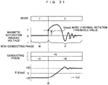
- Patent Document 1 when pulse voltages are applied to two phases of a PM motor, an induced voltage corresponding to a position of a rotor of the PM motor is generated in a non-conducting phase. Therefore, when the induced voltage (magnetic saturation induced voltage) is observed, a dependence on a position (angle) of the rotor is observed, and position sensorless driving in a low-speed region can be performed.
- the magnetic saturation induced voltage is a voltage generated in the non-conducting phase, and thus a control side needs to select a detection phase to read the voltage. Therefore, when conducting phases are switched at a time point at which a level of the magnetic saturation induced voltage of the non-conducting phase reaches a preset threshold value while the level is observed, position sensorless driving can be implemented. Here, accuracy of setting of the "threshold value" is important in switching between conducting phases.
- Patent Document 2 JP 2012-10477 A discloses an automatic adjustment function related to the threshold value.
- automatic adjustment of the threshold value is performed in the following procedure. First, for example, a direct current is allowed to flow in mode 1, and a rotor is attracted to a position of the conduction mode. Next, the mode proceeds to a next one, and a direct current is conducted in a similar manner. In this instance, immediately after the modes are switched, a voltage of a non-conducting phase is identical to a threshold voltage. Thereafter, a level of the threshold value, which is important in Patent Document 1, may be obtained from actual equipment by repetition thereof.
- US 2011/234133 A1 describes a drive apparatus and drive method for switching an energization mode when a voltage of a non-energized phase of a brushless motor crosses a threshold.
- the motor may generate a driving force without step out in a stop/low-speed state.
- a threshold value which is an important set constant in sensorless driving.
- Patent Document 2 includes a description on the above-described automatic adjustment of the threshold value. However, Patent Document 2 has the following problems.
- a rotor is once fixed by applying a direct current in a certain conduction mode. Thereafter, the mode is switched to a subsequent conduction mode to conduct a direct current, and an induced voltage obtained immediately after the switching is collected. Therefore, when inertia of a PM motor is small, the rotor moves simultaneously with the switching, and thus an accurate threshold value cannot be collected.
- a PM motor of a 200 V class is designed by optimizing (minimizing) the amount of a magnet of a rotor.
- the PM motor is designed such that a rotating torque is obtained by increasing the number of turns of a stator in many cases.
- the amount of magnetic flux of the PM motor greatly varies due to a current value of the stator.
- an accurate level of the threshold value varies.
- the threshold value needs to be set to an optimum value according to the current value or the rotating torque of the PM motor. Otherwise, sufficient torque that satisfies a specification of the PM motor cannot be obtained, and also there is a possibility that step out or unstable vibration is incurred.
- An object of the invention is to achieve high torque without using a rotor position sensor around a zero speed and provide a highly stable AC electric motor driving control device and an AC electric motor system using the same.
- the invention includes a plurality of means for solving the above-mentioned problem.
- Examples thereof include an AC electric motor control device for selecting and conducting two phases of a three-phase AC electric motor, switching conducting phases based on a comparison between a voltage value of a remaining non-conducting phase and a threshold value for the voltage value, and rotatably driving the three-phase AC electric motor, in which setting of the threshold value is provided with a threshold value detection mode for detecting the threshold value, a rotor of the three-phase AC electric motor is once fixed by direct current (DC) conduction in the threshold value detection mode, and then an AC current is conducted between two phases to obtain the threshold value.
- DC direct current
- a phase U corresponds to the non-conducting phase.
- the induced voltage is a voltage generated when an inductance in the motor minutely changes due to a relation between a flowing current and a magnetic flux of a permanent magnet attached to the rotor of the PM motor, and may be observed in a stopped state. Therefore, when a magnetic saturation induced voltage is observed, a dependence on a position (angle) of the rotor as illustrated in Fig.
- the induced voltage is referred to as the magnetic saturation induced voltage to distinguish the induced voltage from a speed induced voltage which is generated when the rotor rotates.
- the magnetic saturation induced voltage is a voltage generated in the non-conducting phase, and thus a control side needs to select a detection phase to read the voltage.
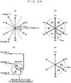
- Fig. 29 illustrates a relation of a conducting phase, a non-conducting phase and a magnetic saturation induced voltage with respect to a position ⁇ d of a rotor.
- Two phases in which a turning force reaches a greatest value are selected as the conducting phase according to ⁇ d.
- the conducting phases are switched at a time point at which a level of the magnetic saturation induced voltage of the non-conducting phase reaches a preset threshold value, that is, Vshp1 to Vshp6 of Fig. 29 while the level is observed, position sensorless driving can be implemented.
- Patent Document 2 discloses an automatic adjustment function related to the threshold value.
- the threshold value is basically determined according to a magnetic circuit characteristic of the motor. However, the threshold value varies depending on a variation in magnetic materials, a manufacturing error, or accuracy of a voltage detection circuit. Therefore, the automatic adjustment function is desired to correct an individual variation of the PM motor or an inverter that drives the PM motor.
- a direct current is allowed to flow in mode 1, and a rotor is attracted to a position of the conduction mode.
- the mode proceeds to a next one, and a direct current is conducted in a similar manner.
- a voltage of a non-conducting phase is identical to a threshold voltage.
- Fig. 30(a) illustrates conducting vectors V1 to V6 of modes 1 to 6.
- V1 is a voltage vector at the time of selecting mode 1 (that is, voltage vector at the time of conducting from the phase U to the phase V).
- Mode 1 is selected when a magnetic flux ⁇ m of the rotor is present in a region M1 of Fig. 30(b) .
- a direct current is allowed to flow in, a magnetic flux due to the current as illustrated in Fig. 30(c) is generated in the motor, and the rotor is attracted thereto to stop.
- a fixed state due to the direct current of V1 corresponds to Fig. 30(d) .
- a position of ⁇ m of Fig. 30(d) is present at a boundary of mode 2 and mode 3. In other words, when an induced voltage of a non-conducting phase at the position is observed, it is possible to obtain a threshold value for proceeding from mode 2 to mode 3.
- a phase of the rotor at the time is 30 [deg].
- a conducting phase is switched to mode 2
- an induced voltage of a phase V of a non-conducting phase is sampled immediately after switching, the sampled voltage corresponds to a threshold value of switching from mode 2 to mode 3.
- Patent Document 2 has a problem in that the rotor moves when an induced voltage is collected immediately after switching, and thus an accurate threshold value cannot be collected, a problem in that a threshold value needs to be set to an optimum value according to a current value or a rotating torque of the PM motor, and the like.
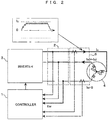
- An object of the control device is to drive a three-phase AC electric motor 4.
- the control device is largely divided into a controller 1, a voltage detector 2, an inverter 3 which includes a DC power source 31, a main inverter circuit 32, and a gate driver 33, and a current sensor 5.
- the three-phase AC electric motor (PM motor) 4 corresponding to an object to be driven and the control device are included in an AC electric motor system.
- the PM motor is given as an example of the object to be driven.
- another type of AC electric motor may be applied if the AC electric motor is an electric motor, a magnetic saturation characteristic of which can be obtained with respect to a rotor position.
- the controller 1 includes a multiplexer 11 for selecting an induced voltage of a non-conducting phase from three phases, a threshold value detector 12 which is a control block for detecting a threshold value, a speed/current controller 13 which functions at the time of conduction driving, a switcher 14 for switching between a conduction driving time and a threshold value detection mode, and a pulse width modulation (PWM) generator 15 for pulse width modulation of a voltage instruction.
- PWM pulse width modulation
- the switcher 14 In conduction driving, the switcher 14 is switched to a side "A", and conducting phases are switched while an induced voltage of a non-conducting phase, which is detected each time sampling is performed, is compared with a preset threshold value. In this instance, a torque and an RPM of the PM motor are controlled in this block.
- An operation of the speed/current controller 13 basically uses a known technology without change.
- the switcher 14 is switched to a side "B", and conducting to the PM motor is performed according to a preset flow to accurately obtain a "threshold value", which is important at the time of conduction driving.
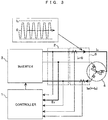
- a direct current is conducted from a phase U to a phase V.
- a magnetic flux due to the direct current is generated inside the PM motor 4, and a rotor is moved and fixed thereto such that the rotor is attracted thereto.
- a phase U is a positive phase
- a phase V is a negative phase, which corresponds to conduction of mode 1.
- conducting phases are switched, and conducting from the phase U to a phase W is performed as illustrated in Fig. 3 .
- an alternating current an average of which is zero
- Conducting from the phase U to the phase W corresponds to mode 2.
- a threshold voltage may be obtained by conduction of this AC current.
- a frequency corresponding to a carrier frequency at the time of performing PWM is considered suitable for a frequency of an alternating current flowing for measurement of a threshold value.
- another frequency has no problem when an induced voltage is sufficiently obtained at the frequency.
- vibrations may be generated in the rotor, and thus it is not preferable.
- a frequency depends on a structure of the rotor, a frequency of hundreds of Hz or more has no problem when a mechanical time constant is considered.
- the condition may be satisfied by changing an amplitude of an AC current such that an alternating current corresponding to an actual driving current flows.
- a flowchart illustrating this operation corresponds to Fig. 4 .
- a direct current is conducted in A01.
- the rotor is fixed, and then conduction modes are switched to conduct an alternating current in A02.
- An induced voltage of a non-conducting phase (phase W) obtained in this state corresponds to a threshold value of switching from mode 2 to mode 3.
- phase W an induced voltage of a non-conducting phase obtained in this state
- all threshold values of the PM motor are targets in principle.
- switching threshold values of six respective modes are obtained from one threshold value.
- the rotor of the three-phase AC electric motor is once fixed by DC conduction, and then an AC current is conducted between two phases to obtain a threshold value.
- the AC electric motor control device when used, it is possible to accurately obtain a threshold value, which is important in sensorless driving. When conducting phases are successively switched using the obtained threshold, it is possible to achieve a position sensorless driving system from a low speed capable of performing high-torque driving.
- a threshold value is obtained only once, and threshold values of six respective modes are determined based on a level of the obtained threshold value.
- an induced voltage is likely to be different among respective phases due to a manufacturing error or a variation in a magnetic material of the motor.
- a detection circuit for detecting an induced voltage is different among respective phases.
- threshold values are obtained with respect to all conduction modes.
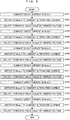
- a direct current is conducted in mode 1 in A01.
- the mode is switched to mode 2 to apply an alternating current in A02, and Vshp2 corresponding to an induced voltage at this time is obtained in A03.
- a direct current is conducted in mode 2 in A04.
- the mode is switched to mode 3 to apply an alternating current in S05, and Vshp3 corresponding to an induced voltage at this time is obtained in A06.
- an operation of conducting a direct current, switching modes to apply an alternating current, and collecting a threshold value is repeated. In this way, when DC conduction and AC conduction are performed while conduction modes are switched, correct switching threshold values may be obtained in all modes.
- the rotor is once fixed by conducting a direct current between two phases of the three-phase AC electric motor. Thereafter, a threshold voltage is obtained by conducting an AC current between two phases corresponding to a different combination from the phases between which the direct current is conducted. A threshold value is detected through at least one combination of the DC conduction and the AC conduction.
- Embodiment 3 of the invention uses Figs. 6, 7 , and 8 .
- the present embodiment proposes a method of setting a threshold value in consideration of a reverse rotation.
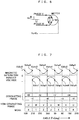
- Bipolar PWM illustrated in Fig. 6 is adopted to implement normal rotation and reverse rotation.
- Bipolar refers to a PWM scheme in which pulses are formed without fail both on a positive side and a negative side.
- a relation of Fig. 7 is obtained.
- Fig. 8 ( Fig. 8A and Fig. 8B ) is a flowchart for automatically measuring the threshold values. Similarly to Fig. 5 , the threshold values are obtained with respect to all conduction modes.
- a direct current is conducted in mode 1 in B01.
- an alternating current is conducted in mode 2 in B02, and a threshold value from mode 2 to mode 3 is set.
- the mode is switched to mode 3, and an alternating current is conducted again in B03.
- a threshold value of reverse rotation from mode 3 to mode 2 is obtained. Since a position of the rotor fixed in mode 1 is present on a boundary line of modes 2 and 3 as illustrated in Fig. 30(d) , it is possible to obtain both a threshold value in the normal rotation direction from mode 2 to mode 3 and a threshold value in the reverse rotation direction from mode 3 to mode 2 at a time.
- the rotor is once fixed by conducting a direct current between two phases of the three-phase AC electric motor. Thereafter, threshold voltages are obtained by conducting AC currents between two types of two phases, respectively, corresponding to different combinations from the phases between which the direct current is conducted. The threshold values are detected through at least one combination of the DC conduction and the AC conduction.
- a current having a strength equivalent to a strength obtained at the time of actual driving of a PM motor may flow, and a more accurate threshold value may be obtained.
- An AC current does not generate an average turning force since an average value thereof is zero.
- a rotor may instantaneously move. In this instance, the rotor may move in various manners depending on inertia or friction of the rotor. However, it is desirable that a steep variation be avoided as possible by implementing soft start.
- the present embodiment provides an operation for gradually increasing amplitude of an AC current such that a shock is not delivered to the rotor as possible when an alternating current starts to be applied.
- Fig. 9 is a block diagram of a controller 1B corresponding to a particular part of the present embodiment. When this block is used instead of the controller 1 of Fig. 1 , the fourth embodiment may be implemented.
- a voltage limiter 16 is newly applied in Fig. 9 . However, other blocks are the same as those of Fig. 1 .
- the voltage limiter 16 limits a rate of change of amplitude of an AC voltage applied to the PM motor when a threshold voltage is obtained.
- a current waveform gradually increases in a form of a lamp as in Fig. 10 , and an impact on the rotor may be removed.
- a current having a strength equivalent to a strength obtained at the time of actual driving of a PM motor may flow, and a more accurate threshold value may be obtained.
- a current, which is obtained when an alternating current is applied has a dependence on a frequency in addition to amplitude of the alternating current. Thus, a sufficient AC current may not be allowed to flow depending on conditions.
- Figs. 12 to 14 This phenomenon will be described using Figs. 12 to 14 .
- a pulse-like AC voltage is applied between lines of a phase V and a phase W as in Fig. 12 (a condition of conduction mode 3)
- a phase current Iv is generated, but a maximum value (peak value) Ip thereof does not reach a predetermined value 10. Therefore, a pulse width is increased up to a maximum as in Fig. 13 .
- the value 10 is not reached.
- a maximum current up to a desired value may flow when a frequency of an alternating current is decreased as in Fig. 14 .
- Fig. 11 is a block diagram of a controller 1C corresponding to a particular part of the present embodiment. When this block is used instead of the controller 1 of Fig. 1 , Embodiment 5 may be implemented.
- An AC frequency setting unit 17 and a current setting unit 18 are newly applied in Fig. 11 .
- other blocks are the same as those of Fig. 1 .
- the AC frequency setting unit 17 verifies whether a peak value of a phase current is identical to a value 10 set by the current setting unit 18, and performs an operation such that an AC frequency is decreased when the values are not identical to each other. As a result of this operation, an AC current having strength required for acquisition of a threshold value may be applied to a PM motor, and detection accuracy of a threshold value may be ensured.
- the controller includes a means having a function of presetting amplitude of an AC current to adjust a frequency of the AC current such that a set value of the amplitude of the AC current is reached.
- the above embodiments describe a means for obtaining a highly precise threshold value.
- the present embodiment describes an algorithm corresponding to a case in which a PM motor is driven actually using the obtained threshold value.
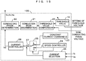
- Fig. 15 is a block diagram of a speed/current controller 13D corresponding to a particular part of the present embodiment.
- this block is used instead of the speed/current controller 13 of Fig. 1 , Embodiment 6 may be implemented.
- the speed/current controller 13D includes a threshold value setting unit 19 for setting a threshold value, a threshold value comparator 20 for comparing a detection value of an induced voltage of a non-conducting phase with the threshold value, a conduction mode discrimination unit 21 for determining a mode of conduction to the PM motor based on an output of the threshold value comparator, a conducting phase determination unit 22 for determining a voltage instruction V0 and a three-phase voltage instruction to perform a conduction operation designated by the conduction mode discrimination unit 21, a constant current instruction 10 setting unit 23 for setting a current during activation, a speed controller 24 for outputting a current instruction to control RPM of a PM motor 4, a switcher 25 for switching the current instruction for the PM motor to a constant current instruction or the output of the threshold value comparator, a current selector 26 for selecting a controlled phase current, a subtracter 27 for calculating a deviation between the current instruction and an actual current value, and a current controller 28 for calculating a
- a threshold value is detected as an optimum value with respect to a predetermined current value, and the value is stored in the threshold value setting unit 19. Therefore, when an induced voltage of a non-conducting phase is compared with the threshold value, conduction modes may be ideally switched. However, when a current value obtained when the threshold value is measured is different from an actually flowing current value, ideal switching cannot be achieved. Therefore, the present embodiment is characterized in that the PM motor is driven by a constant current such that the threshold value is identical to an acquired current.
- a current equivalent to a current value used for measurement of a threshold value is set in the constant current instruction 10 setting unit 23.
- the switcher 25 is switched to a side "L", and a current instruction of a constant value 10 is constantly supplied to the current controller 28.
- a driving current corresponds to a condition of a set threshold value, and thus ideal torque driving may be implemented at all the times.
- the switcher 25 is switched to a side "H” such that driving is switched to sensorless driving by a speed induced voltage when RPM increases, and the speed induced voltage becomes great, speed control may be implemented as in the past.
- a switching speed ⁇ r0 depends on a characteristic of the PM motor, and is in a range of about 5% to 15%.
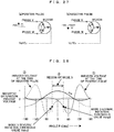
- Fig. 16 illustrates activation waveforms when the present embodiment is used.
- Fig. 16(a) corresponds to an activation waveform from zero when inertia of a mechanical system including a rotor is small.
- a speed is increased by performing a control operation such that a current has a constant value 10 from an activation start time t0 to a time t1 at which a speed ⁇ r0 is reached.
- current instructions are switched by the switcher 25, and the speed controller 24 starts to operate.
- a rotation speed increases according to a setting response of the speed controller, and reaches a speed instruction ⁇ r*.
- a speed instantaneously increases at a constant current, and a low-speed region is passed in an instant.
- a speed is increased by performing a control operation such that a current is identical to a preset value, and then a speed control function is operated to control rotation.
- Embodiment 6 relates to an algorithm corresponding to a case in which a PM motor is driven actually using an obtained threshold value, and may implement unprecedented high-torque driving.
- a speed cannot be controlled since a low-speed region corresponds to constant current driving.
- the present embodiment shows an example that solves this problem.
- Fig. 17 is a block diagram of a speed/current controller 13E corresponding to a particular part of the present embodiment.
- this block is used instead of the speed/current controller 13 of Fig. 1 , Embodiment 7 may be implemented.
- the speed/current controller 13E when compared to the speed/current controller 13D described above, the speed/current controller 13E newly provides a harmonic generator 29, and further includes an adder 30 for adding an output of the harmonic generator 29 to a voltage instruction V0. Furthermore, the constant current instruction 10 setting unit 23 and the switcher 25 of Fig. 15 are removed.
- the threshold value setting unit 19, the threshold value comparator 20, the conduction mode discrimination unit 21, the conducting phase determination unit 22, the speed controller 24, the subtracter 27, and the current controller 28 corresponding to the other components are the same as those in Embodiment 6.
- driving by a constant current is not implemented particularly in a low-speed region.
- a current is controlled based on the speed controller 24 from the time of activation.
- current strength is determined by the speed controller, and thus may become an arbitrary value.
- the current strength may be different from a value set to a threshold value. Therefore, the harmonic generator 29 is introduced to control a ripple component contained in a current and intentionally apply harmonics such that a current peak corresponding to a condition at which the threshold value is obtained is maintained at all the times.
- Fig. 18 This state is illustrated in Fig. 18 .
- a current is set to 10 at the time of acquisition of a threshold value, and current strength is set to a 100% current, the amount of harmonics is increased by the harmonic generator 29 at the time of no load, and a peak value is adjusted to reach 10 ( Fig. 18(a) ).
- current strength is set to a 50% current
- the amount of harmonics is adjusted such that a peak value reaches 10 ( Fig. 18(b) ).
- a current corresponding to 10 is obtained only by a fundamental harmonic, and thus harmonics become unnecessary ( Fig. 18(c) ).
- a control operation is performed by adding a harmonic component to a voltage such that a peak value of a current flowing through a conducting phase is identical to a preset value at the time of conduction driving of an AC electric motor.
- Embodiment 7 the amount of harmonics is controlled such that an obtained threshold value is identical to a peak value of an actual current, thereby implementing stable speed control from a low-speed region. Even though this scheme is convenient, harmonics need to be applied. Thus, this scheme does not consider an increase in unnecessary electromagnetic noise or harmonic loss.
- the present embodiment shows an example that solves this problem.
- Fig. 19 is a block diagram of a speed/current controller 13F corresponding to a particular part of the present embodiment.
- this block is used instead of the speed/current controller 13 of Fig. 1 , Embodiment 8 can be implemented.
- the speed/current controller 13F when compared to the above-described speed/current controller 13E, the speed/current controller 13F is mainly characterized in that a threshold value setting unit 19F is newly provided, and the harmonic generator 29 and the adder 30 are removed.
- the threshold value setting unit 19F stores a threshold value in each conduction mode. However, herein, a threshold value appropriate for a current value is mapped and maintained. As illustrated in Fig. 20 , an appropriate value of a threshold value may be changed according to a conducted current, and a threshold value with respect to this current is obtained in the above-described threshold value detection mode. For example, when a voltage of a non-conducting phase is obtained in a process of gradually increasing an AC current value, and this value is maintained as in Embodiment 4, a threshold value appropriate for a current may be easily obtained.
- table data is stored in the threshold value setting unit 19F based on threshold value information with respect to a current value obtained in this way, and a threshold value is appropriately changed according to a current, conduction modes may be switched in an optimum state at all the times.
- a relation between a threshold value and a current value obtained in a threshold value detection mode at the time of conduction driving of an AC electric motor is incorporated as a data map or a function, and a threshold value with respect to a driving current is calculated based on the data map or the function to drive the AC electric motor.
- Embodiment 9 of the invention uses Figs. 21 to 23 .
- the present embodiment describes an example related to pre-adjustment for detecting an induced voltage of a non-conducting phase including threshold value detection.
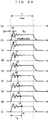
- a pulse-like AC voltage Vvw is applied as illustrated in Fig. 21(a)
- a current as in Fig. 21(b) is generated, and an induced voltage Eu of a non-conducting phase is generated.
- Fig. 21(c) ringing associated with switching is generated in an actual induced voltage. Therefore, in order to avoid this ringing, the induced voltage needs to be sampled in a predetermined time T after switching ( Fig. 21(d) ).
- the predetermined time T is sufficiently short, a voltage in ringing is sampled as in Fig. 21(e) , and a correct non-conducting phase voltage cannot be detected.
- a ringing frequency is in a region of several tens of kHz to several MHz. Detection cannot be performed in an operation period of motor control in which a sampling period is several hundreds of ⁇ s .
- sampling timing of the non-conducting phase voltage Eu is delayed in each arithmetic processing period, and a period in which ringing is generated is detected.
- Fig. 22(a) illustrates a state in which a line voltage Vvw is applied for a period T0 at a time t0.
- This voltage is not repeatedly applied to a motor, and thus an induced voltage associated with the same ringing is generated in the non-conducting phase each time.
- the voltage Eu is sampled at a time t1 delayed from the time t0 by a minute time ⁇ t.
- sampling is performed at a time t2 further delayed by ⁇ t.
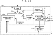
- Fig. 23 is a block diagram of a controller 1G corresponding to a particular part of the present embodiment. When this block is used instead of the controller 1 of Fig. 1 , Embodiment 9 may be implemented.
- the controller 1G when compared to the controller 1C of Fig. 11 , the controller 1G is mainly characterized in that a ringing extractor 41 and a switcher 14g are newly provided.
- this block An operation of this block is as below.
- the switcher 14g is switched to a side "D" to extract a ringing time.
- the ringing extractor 41 repeatedly applies a pulse as described above.
- a non-conducting phase voltage is obtained by changing sampling timing.
- a convergence time T of ringing is acquired, and a minimum pulse width or a harmonic frequency is set according to the acquired convergence time T.
- a voltage waveform of a non-conducting phase is sampled a plural number of times, a vibration range at the time of a rise in the voltage waveform is detected, and voltage detection timing is set to avoid the detected range.
- the sampling performed the plural number of times is presumed to be performed in each arithmetic processing period, and may be implemented by gradually delaying sampling timing.
- Embodiment 10 of the invention uses Figs. 24 and 25 .
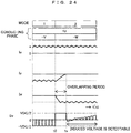
- the present embodiment describes an example related to a method of obtaining an overlapping period which is an adjustment element peculiar to 120° conduction driving.
- a conduction mode when a conduction mode is switched from mode 1 to mode 2 at a time t0, a current of a phase U continuously flows, but a current is switched from a phase V to a phase W.
- the current of the phase V does not instantly become zero, and is gradually decreased via a free wheel diode.
- the current of the phase W rises at the same time, and thus the currents simultaneously flow in the three phases in an instant.
- This period (a period between a time t0 to a time ts of Fig. 24 ) is referred to as an overlapping period.
- This period corresponds to a decay time of a current when a conducting phase is changed, and corresponds to a period in which an induced voltage of a non-conducting phase cannot be detected since the phase V, which originally needs to be a non-conducting phase, is conducted.
- this period becomes a "standby" period. Since the induced voltage of the non-conducting phase needs to be sampled while avoiding this period, this period needs to be set in advance. As it is understood from Fig. 24 , during the overlapping period, since the induced voltage of the non-conducting phase is inevitably clamped to a positive or a negative of a DC voltage, the overlapping period can be confirmed. This period is counted and set as the overlapping period with a margin corresponding to 1 and 2 samples by further taking a transient variation into consideration, and the non-conducting phase is detected.
- Fig. 25 is a block diagram of a controller 1H corresponding to a particular part of the present embodiment. When this block is used instead of the controller 1 of Fig. 1 , Embodiment 10 may be implemented.
- the controller 1H when compared to the controller 1G of Fig. 23 , the controller 1H is mainly characterized in that an overlapping period extractor 42 and a switcher 14h are newly provided.
- this block Before implementing a threshold value detection mode or a ringing extraction mode, the switcher 14h is switched to a side "E" to extract an overlapping period.
- the overlapping period extractor 42 changes a mode in a conducting state as described above to sample a non-conducting phase voltage.
- a period in which a result of sampling is clamped to a DC voltage of an inverter corresponds to the overlapping period, and thus the period is counted and set as the overlapping period by adding a margin corresponding to 1 and 2 samples from when clamping is released.
- a voltage of a non-conducting phase obtained when a conducting phase is changed is sampled to measure a decay time of a current obtained when the conducting phase is changed, and the overlapping period, in which comparison between a voltage value of the non-conducting phase and a threshold value with respect to the voltage value is not performed, is extracted.
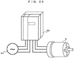
- Fig. 26 illustrates an AC electric motor system which uses the general-purpose inverter and includes a three-phase AC power supply 44, the general-purpose inverter 45, and a PM motor 4.
- the general-purpose inverter 45 operates as a controller of the PM motor 4 (AC electric motor) corresponding to an object to be driven.
- the controller 1, the voltage detector 2, the inverter 3, and the current sensor 5 described in the above embodiments are included inside the general-purpose inverter 45.
- the DC power source 31 inside the inverter 3 of Fig. 1 obtains a DC source by rectifying and smoothing the three-phase AC power supply 44.
- the controller 1 included in the general-purpose inverter 45 is equipped with a means of the above-described embodiments.
- the above-described embodiments may accurately extract a threshold value of the PM motor 4, and perform high-response and high-torque driving from a low speed. Therefore, the above-described embodiments of the invention are particularly suitable for an apparatus such as the general-purpose inverter that presumes connection of various motors. In other words, it is possible to implement high-torque and high-response sensorless driving by connecting an arbitrary motor and extracting a threshold value.
- the above-described embodiments are not limited to the general-purpose inverter, and are applicable to a conveyor, an elevator, an extruding machine, a machine tool, and the like in addition to control of a rotation speed of a compressor (for air conditioning or for a refrigerator), a fan, a pump (a water pump or an oil pump), a spindle motor, a heating-cooling combination appliance, and the like.
- Embodiments have been described. However, the invention is not restricted to the above-described embodiments and includes various modified examples. For example, the above-described embodiments are described in detail to facilitate the understanding of the invention, and the invention is not restricted to including all described components. Further, a part of a component of an embodiment may be replaced by a component of another embodiment, and a component of an embodiment may be added to a component of another embodiment. Furthermore, with respect to a portion of a component of each embodiment, another component may be added, removed, and replaced.
Landscapes
- Engineering & Computer Science (AREA)
- Power Engineering (AREA)
- Control Of Motors That Do Not Use Commutators (AREA)
- Control Of Ac Motors In General (AREA)
Claims (12)
- Dispositif de commande de moteur électrique à courant alternatif (AC) pour sélectionner et conduire deux phases d'un moteur électrique à courant alternatif triphasé (4), commuter des phases conductrices sur la base d'une comparaison entre une valeur de tension d'une phase non conductrice restante et une valeur de seuil pour la valeur de tension, et actionner la rotation du moteur électrique à courant alternatif triphasé (4),
caractérisé en ce que :le réglage de la valeur de seuil est pourvu d'un mode de détection de valeur de seuil, un rotor du moteur électrique à courant alternatif triphasé (4) est fixé, une fois, par conduction de courant continu (DC) dans le mode de détection de valeur de seuil, et ensuite un courant alternatif, dont une moyenne est nulle, est conduit entre deux phases (U, V, W) en vue d'obtenir la valeur de seuil ; eten ce qu'une fonction d'échantillonnage d'une forme d'onde de tension de la phase non conductrice, à plusieurs reprises, de détection d'une plage de vibration au moment d'une élévation de la forme d'onde de tension, et de réglage d'une temporisation de détection de tension pour éviter la plage détectée, est fournie en tant qu'une opération à un instant de démarrage du mode de détection de valeur de seuil pour détecter une tension induite d'une phase non conductrice incluant une détection de valeur de seuil. - Dispositif de commande de moteur électrique à courant alternatif selon la revendication 1, dans lequel, dans le mode de détection de valeur de seuil, après que le rotor a été fixé une fois en conduisant un courant continu entre les deux phases du moteur électrique à courant alternatif triphasé (4), un courant alternatif est conduit entre deux phases (U, V, W) correspondant à une combinaison différente des deux phases (U, V, W) entre lesquelles le courant continu est conduit, pour obtenir la valeur de seuil, et la valeur de seuil est détectée en mettant en œuvre au moins une combinaison de la conduction de courant continu et de la conduction de courant alternatif.
- Dispositif de commande de moteur électrique à courant alternatif selon la revendication 1, dans lequel, dans le mode de détection de valeur de seuil, après que le rotor a été fixé une fois en conduisant un courant continu entre les deux phases du moteur électrique à courant alternatif triphasé (4), des tensions de seuil sont obtenues en conduisant des courants alternatifs entre deux types de deux phases (U, V, W), respectivement, correspondant à des combinaisons différentes des deux phases (U, V, W) entre lesquelles le courant continu est conduit, et les valeurs de seuil sont détectées en mettant en œuvre au moins une combinaison de la conduction de courant continu et de la conduction de courant alternatif.
- Dispositif de commande de moteur électrique à courant alternatif selon l'une quelconque des revendications 1 à 3, dans lequel l'amplitude du courant alternatif conduit est progressivement augmentée à partir d'un début de conduction dans le mode de détection de valeur de seuil.
- Dispositif de commande de moteur électrique à courant alternatif selon l'une quelconque des revendications 1 à 4, comprenant :
un moyen présentant une fonction de préréglage d'amplitude d'un courant alternatif dans le mode de détection de valeur de seuil pour ajuster une fréquence du courant alternatif, de sorte qu'une valeur de consigne de l'amplitude du courant alternatif est atteinte. - Dispositif de commande de moteur électrique à courant alternatif selon l'une quelconque des revendications 1 à 5, dans lequel une vitesse est augmentée en mettant en œuvre une opération de commande, de sorte qu'un courant est identique à une valeur préréglée à un instant d'activation au cours d'un actionnement de conduction du moteur électrique à courant alternatif (4), et ensuite une fonction de commande de vitesse est actionnée en vue de commander la rotation.
- Dispositif de commande de moteur électrique à courant alternatif selon l'une quelconque des revendications 1 à 5, dans lequel une opération de commande est mise en œuvre en ajoutant une composante harmonique à une tension, de sorte qu'une valeur de crête d'un courant circulant à travers la phase conductrice est identique à une valeur préréglée à un instant d'actionnement de conduction du moteur électrique à courant alternatif.
- Dispositif de commande de moteur électrique à courant alternatif selon l'une quelconque des revendications 1 à 5, dans lequel une relation entre la valeur de seuil et une valeur de courant obtenue dans le mode de détection de valeur de seuil, à un instant d'actionnement de conduction du moteur électrique à courant alternatif (4), est incorporée sous la forme d'une carte de données ou d'une fonction, et une valeur de seuil relativement à un courant d'actionnement est calculée sur la base de la carte de données ou de la fonction pour actionner le moteur électrique à courant alternatif (4).
- Dispositif de commande de moteur électrique à courant alternatif selon la revendication 1, dans lequel l'échantillonnage mis en œuvre à plusieurs reprises est présumé être mis en œuvre à chaque période de traitement arithmétique, et est mis en œuvre en retardant progressivement la temporisation d'échantillonnage.
- Dispositif de commande de moteur électrique à courant alternatif selon l'une quelconque des revendications 1 à 9, dans lequel,
avant que le mode de détection de valeur de seuil ne soit mis en œuvre,
une tension d'une phase non conductrice (U, V, W), obtenue lorsque la phase conductrice est modifiée, est échantillonnée en vue de mesurer un temps de décroissance d'un courant obtenu lorsque la phase conductrice est modifiée ; et
une période de chevauchement, au cours de laquelle une comparaison entre une valeur de tension de la phase non conductrice et une valeur de seuil relativement à la valeur de tension n'est pas mise en œuvre, est extraite. - Dispositif de commande de moteur électrique à courant alternatif selon l'une quelconque des revendications 1 à 10, comprenant en outre :un contrôleur (1) pour obtenir la valeur de seuil ;un détecteur de tension (2) destiné à détecter une valeur de tension de chaque phase (U, V, W) du moteur électrique à courant alternatif triphasé (4) ;un capteur de courant (31) destiné à détecter un courant de chaque phase du moteur électrique à courant alternatif triphasé (4) ; etun onduleur (3).
- Système de moteur électrique à courant alternatif comprenant :le dispositif de commande de moteur électrique à courant alternatif selon l'une quelconque des revendications 1 à 11 ; etun moteur électrique à courant alternatif (4) actionné par le dispositif de commande.
Applications Claiming Priority (2)
| Application Number | Priority Date | Filing Date | Title |
|---|---|---|---|
| JP2013185040A JP6002643B2 (ja) | 2013-09-06 | 2013-09-06 | 制御装置およびそれを用いた交流電動機システム |
| PCT/JP2014/067439 WO2015033651A1 (fr) | 2013-09-06 | 2014-06-30 | Dispositif de commande et système de moteur électrique en ca l'utilisant |
Publications (3)
| Publication Number | Publication Date |
|---|---|
| EP3043465A1 EP3043465A1 (fr) | 2016-07-13 |
| EP3043465A4 EP3043465A4 (fr) | 2017-11-15 |
| EP3043465B1 true EP3043465B1 (fr) | 2021-03-24 |
Family
ID=52628140
Family Applications (1)
| Application Number | Title | Priority Date | Filing Date |
|---|---|---|---|
| EP14842384.1A Active EP3043465B1 (fr) | 2013-09-06 | 2014-06-30 | Dispositif de commande et système de moteur électrique en ca l'utilisant |
Country Status (4)
| Country | Link |
|---|---|
| EP (1) | EP3043465B1 (fr) |
| JP (1) | JP6002643B2 (fr) |
| CN (1) | CN105453410B (fr) |
| WO (1) | WO2015033651A1 (fr) |
Families Citing this family (7)
| Publication number | Priority date | Publication date | Assignee | Title |
|---|---|---|---|---|
| JP6634167B2 (ja) * | 2016-12-28 | 2020-01-22 | 株式会社日立産機システム | 電力変換装置 |
| JP6707050B2 (ja) | 2017-03-27 | 2020-06-10 | 株式会社日立産機システム | 同期電動機の制御装置 |
| JP6324600B1 (ja) * | 2017-07-06 | 2018-05-16 | 北斗制御株式会社 | 電動機の界磁位置検出方法 |
| EP3536461B1 (fr) * | 2018-03-08 | 2020-11-25 | Andreas Stihl AG & Co. KG | Procédé de fonctionnement dépendant du type d'une unité d'entraînement électrique et système |
| CN112740540B (zh) * | 2018-09-26 | 2024-09-13 | 西门子股份公司 | 用于运行具有转子和软起动器的永磁激励的三相电机的方法和三相电机 |
| TWI697194B (zh) * | 2019-07-04 | 2020-06-21 | 微星科技股份有限公司 | 永磁馬達轉子位置偵測裝置及其方法 |
| CN112865616B (zh) * | 2021-03-16 | 2022-05-24 | 浙江沪龙科技股份有限公司 | 一种抑制无刷直流电机转矩脉动的pwm控制方法 |
Family Cites Families (10)
| Publication number | Priority date | Publication date | Assignee | Title |
|---|---|---|---|---|
| JP5069882B2 (ja) * | 2006-08-30 | 2012-11-07 | 日立アプライアンス株式会社 | 三相コンバータ・インバータ装置及びモジュール |
| JP2008113506A (ja) * | 2006-10-31 | 2008-05-15 | Renesas Technology Corp | モータ駆動制御装置およびモータ起動方法 |
| JP5175569B2 (ja) | 2008-02-07 | 2013-04-03 | ルネサスエレクトロニクス株式会社 | 同期電動機の駆動システム |
| JP5308109B2 (ja) * | 2008-09-17 | 2013-10-09 | ルネサスエレクトロニクス株式会社 | 同期電動機の駆動システム |
| JP2011200058A (ja) * | 2010-03-23 | 2011-10-06 | Hitachi Automotive Systems Ltd | ブラシレスモータの駆動装置 |
| JP5356320B2 (ja) * | 2010-06-24 | 2013-12-04 | 日立オートモティブシステムズ株式会社 | ブラシレスモータの駆動装置 |
| US8710788B2 (en) * | 2010-03-23 | 2014-04-29 | Hitachi Automotive Systems, Ltd. | Brushless motor drive apparatus and drive method |
| JP5439262B2 (ja) * | 2010-04-02 | 2014-03-12 | 日立オートモティブシステムズ株式会社 | 放電処理装置、放電処理方法、および放電処理プログラム |
| JP5509167B2 (ja) * | 2011-09-08 | 2014-06-04 | 株式会社日立産機システム | 同期電動機の制御システム |
| JP5438081B2 (ja) * | 2011-09-21 | 2014-03-12 | 日立オートモティブシステムズ株式会社 | ブラシレスモータの駆動装置 |
-
2013
- 2013-09-06 JP JP2013185040A patent/JP6002643B2/ja not_active Expired - Fee Related
-
2014
- 2014-06-30 EP EP14842384.1A patent/EP3043465B1/fr active Active
- 2014-06-30 WO PCT/JP2014/067439 patent/WO2015033651A1/fr active Application Filing
- 2014-06-30 CN CN201480043410.2A patent/CN105453410B/zh not_active Expired - Fee Related
Non-Patent Citations (1)
| Title |
|---|
| None * |
Also Published As
| Publication number | Publication date |
|---|---|
| CN105453410B (zh) | 2017-12-15 |
| JP6002643B2 (ja) | 2016-10-05 |
| EP3043465A4 (fr) | 2017-11-15 |
| WO2015033651A1 (fr) | 2015-03-12 |
| JP2015053800A (ja) | 2015-03-19 |
| EP3043465A1 (fr) | 2016-07-13 |
| CN105453410A (zh) | 2016-03-30 |
Similar Documents
| Publication | Publication Date | Title |
|---|---|---|
| EP3043465B1 (fr) | Dispositif de commande et système de moteur électrique en ca l'utilisant | |
| EP3751724A1 (fr) | Commande de moteur sans balai et sans capteur agissant sur le champ dans un outil électrique | |
| US9590552B2 (en) | Motor drive device and electric compressor | |
| AU2013294419B2 (en) | Motor drive control device | |
| US6900613B2 (en) | Motor control apparatus | |
| JP3805336B2 (ja) | 磁極位置検出装置及び方法 | |
| JP2003199389A (ja) | モータの制御装置及びその制御方法 | |
| JP2015109792A (ja) | Bldcモータにおける相電流調整 | |
| US8664905B2 (en) | Control of brushless motor | |
| JP2015080344A (ja) | 電動機の駆動装置 | |
| JP2009077503A (ja) | 電動機の制御装置,空気調和機の制御装置 | |
| EP2755319B1 (fr) | Système de commande de moteur synchrone | |
| JP2016163518A (ja) | 回転位置検出装置,モータ制御装置及び回転位置検出方法 | |
| US11177744B2 (en) | Method for starting and operating a BLDC motor and BLDC motor | |
| KR20180082128A (ko) | 상전압 검출을 이용한 브러시리스 직류모터 기동 제어방법 및 장치 | |
| JP2019057981A (ja) | モータ制御用集積回路 | |
| JP2019022403A (ja) | 電動機用インバータ回路の評価装置および評価方法 | |
| KR20000046679A (ko) | 동기식 리럭턴스 모터의 속도제어 방법 및 장치 | |
| JP6348779B2 (ja) | 同期電動機の駆動システム | |
| US20230142956A1 (en) | Motor controller, motor system and method for controlling motor | |
| Hara et al. | Neutral point voltage model of stator windings of permanent magnet synchronous motors with magnetic asymmetry | |
| WO2018100626A1 (fr) | Système de commande de moteur synchrone à aimants permanents, et procédé de commande de moteur synchrone à aimants permanents | |
| JP7433113B2 (ja) | モータ制御装置、モータシステム及びモータ制御方法 | |
| US20240291417A1 (en) | Inverter control device and inverter control method | |
| JP2009247134A (ja) | ロータ位置検出装置、ロータ位置検出方法、モータの制御装置、及びモータの制御方法 |
Legal Events
| Date | Code | Title | Description |
|---|---|---|---|
| PUAI | Public reference made under article 153(3) epc to a published international application that has entered the european phase |
Free format text: ORIGINAL CODE: 0009012 |
|
| 17P | Request for examination filed |
Effective date: 20160204 |
|
| AK | Designated contracting states |
Kind code of ref document: A1 Designated state(s): AL AT BE BG CH CY CZ DE DK EE ES FI FR GB GR HR HU IE IS IT LI LT LU LV MC MK MT NL NO PL PT RO RS SE SI SK SM TR |
|
| AX | Request for extension of the european patent |
Extension state: BA ME |
|
| DAX | Request for extension of the european patent (deleted) | ||
| A4 | Supplementary search report drawn up and despatched |
Effective date: 20171016 |
|
| RIC1 | Information provided on ipc code assigned before grant |
Ipc: H02P 23/03 20060101ALI20171010BHEP Ipc: H02P 6/18 20160101AFI20171010BHEP Ipc: H02P 6/185 20160101ALI20171010BHEP |
|
| GRAP | Despatch of communication of intention to grant a patent |
Free format text: ORIGINAL CODE: EPIDOSNIGR1 |
|
| STAA | Information on the status of an ep patent application or granted ep patent |
Free format text: STATUS: GRANT OF PATENT IS INTENDED |
|
| INTG | Intention to grant announced |
Effective date: 20201118 |
|
| GRAS | Grant fee paid |
Free format text: ORIGINAL CODE: EPIDOSNIGR3 |
|
| GRAA | (expected) grant |
Free format text: ORIGINAL CODE: 0009210 |
|
| STAA | Information on the status of an ep patent application or granted ep patent |
Free format text: STATUS: THE PATENT HAS BEEN GRANTED |
|
| AK | Designated contracting states |
Kind code of ref document: B1 Designated state(s): AL AT BE BG CH CY CZ DE DK EE ES FI FR GB GR HR HU IE IS IT LI LT LU LV MC MK MT NL NO PL PT RO RS SE SI SK SM TR |
|
| REG | Reference to a national code |
Ref country code: GB Ref legal event code: FG4D |
|
| REG | Reference to a national code |
Ref country code: CH Ref legal event code: EP |
|
| REG | Reference to a national code |
Ref country code: IE Ref legal event code: FG4D |
|
| REG | Reference to a national code |
Ref country code: AT Ref legal event code: REF Ref document number: 1375526 Country of ref document: AT Kind code of ref document: T Effective date: 20210415 Ref country code: DE Ref legal event code: R096 Ref document number: 602014076015 Country of ref document: DE |
|
| REG | Reference to a national code |
Ref country code: LT Ref legal event code: MG9D |
|
| PG25 | Lapsed in a contracting state [announced via postgrant information from national office to epo] |
Ref country code: NO Free format text: LAPSE BECAUSE OF FAILURE TO SUBMIT A TRANSLATION OF THE DESCRIPTION OR TO PAY THE FEE WITHIN THE PRESCRIBED TIME-LIMIT Effective date: 20210624 Ref country code: BG Free format text: LAPSE BECAUSE OF FAILURE TO SUBMIT A TRANSLATION OF THE DESCRIPTION OR TO PAY THE FEE WITHIN THE PRESCRIBED TIME-LIMIT Effective date: 20210624 Ref country code: FI Free format text: LAPSE BECAUSE OF FAILURE TO SUBMIT A TRANSLATION OF THE DESCRIPTION OR TO PAY THE FEE WITHIN THE PRESCRIBED TIME-LIMIT Effective date: 20210324 Ref country code: HR Free format text: LAPSE BECAUSE OF FAILURE TO SUBMIT A TRANSLATION OF THE DESCRIPTION OR TO PAY THE FEE WITHIN THE PRESCRIBED TIME-LIMIT Effective date: 20210324 Ref country code: GR Free format text: LAPSE BECAUSE OF FAILURE TO SUBMIT A TRANSLATION OF THE DESCRIPTION OR TO PAY THE FEE WITHIN THE PRESCRIBED TIME-LIMIT Effective date: 20210625 |
|
| PG25 | Lapsed in a contracting state [announced via postgrant information from national office to epo] |
Ref country code: SE Free format text: LAPSE BECAUSE OF FAILURE TO SUBMIT A TRANSLATION OF THE DESCRIPTION OR TO PAY THE FEE WITHIN THE PRESCRIBED TIME-LIMIT Effective date: 20210324 Ref country code: RS Free format text: LAPSE BECAUSE OF FAILURE TO SUBMIT A TRANSLATION OF THE DESCRIPTION OR TO PAY THE FEE WITHIN THE PRESCRIBED TIME-LIMIT Effective date: 20210324 Ref country code: LV Free format text: LAPSE BECAUSE OF FAILURE TO SUBMIT A TRANSLATION OF THE DESCRIPTION OR TO PAY THE FEE WITHIN THE PRESCRIBED TIME-LIMIT Effective date: 20210324 |
|
| REG | Reference to a national code |
Ref country code: NL Ref legal event code: MP Effective date: 20210324 |
|
| REG | Reference to a national code |
Ref country code: AT Ref legal event code: MK05 Ref document number: 1375526 Country of ref document: AT Kind code of ref document: T Effective date: 20210324 |
|
| PG25 | Lapsed in a contracting state [announced via postgrant information from national office to epo] |
Ref country code: NL Free format text: LAPSE BECAUSE OF FAILURE TO SUBMIT A TRANSLATION OF THE DESCRIPTION OR TO PAY THE FEE WITHIN THE PRESCRIBED TIME-LIMIT Effective date: 20210324 |
|
| PG25 | Lapsed in a contracting state [announced via postgrant information from national office to epo] |
Ref country code: SM Free format text: LAPSE BECAUSE OF FAILURE TO SUBMIT A TRANSLATION OF THE DESCRIPTION OR TO PAY THE FEE WITHIN THE PRESCRIBED TIME-LIMIT Effective date: 20210324 Ref country code: CZ Free format text: LAPSE BECAUSE OF FAILURE TO SUBMIT A TRANSLATION OF THE DESCRIPTION OR TO PAY THE FEE WITHIN THE PRESCRIBED TIME-LIMIT Effective date: 20210324 Ref country code: EE Free format text: LAPSE BECAUSE OF FAILURE TO SUBMIT A TRANSLATION OF THE DESCRIPTION OR TO PAY THE FEE WITHIN THE PRESCRIBED TIME-LIMIT Effective date: 20210324 Ref country code: LT Free format text: LAPSE BECAUSE OF FAILURE TO SUBMIT A TRANSLATION OF THE DESCRIPTION OR TO PAY THE FEE WITHIN THE PRESCRIBED TIME-LIMIT Effective date: 20210324 Ref country code: AT Free format text: LAPSE BECAUSE OF FAILURE TO SUBMIT A TRANSLATION OF THE DESCRIPTION OR TO PAY THE FEE WITHIN THE PRESCRIBED TIME-LIMIT Effective date: 20210324 |
|
| PG25 | Lapsed in a contracting state [announced via postgrant information from national office to epo] |
Ref country code: IS Free format text: LAPSE BECAUSE OF FAILURE TO SUBMIT A TRANSLATION OF THE DESCRIPTION OR TO PAY THE FEE WITHIN THE PRESCRIBED TIME-LIMIT Effective date: 20210724 Ref country code: PL Free format text: LAPSE BECAUSE OF FAILURE TO SUBMIT A TRANSLATION OF THE DESCRIPTION OR TO PAY THE FEE WITHIN THE PRESCRIBED TIME-LIMIT Effective date: 20210324 Ref country code: PT Free format text: LAPSE BECAUSE OF FAILURE TO SUBMIT A TRANSLATION OF THE DESCRIPTION OR TO PAY THE FEE WITHIN THE PRESCRIBED TIME-LIMIT Effective date: 20210726 Ref country code: ES Free format text: LAPSE BECAUSE OF FAILURE TO SUBMIT A TRANSLATION OF THE DESCRIPTION OR TO PAY THE FEE WITHIN THE PRESCRIBED TIME-LIMIT Effective date: 20210324 Ref country code: SK Free format text: LAPSE BECAUSE OF FAILURE TO SUBMIT A TRANSLATION OF THE DESCRIPTION OR TO PAY THE FEE WITHIN THE PRESCRIBED TIME-LIMIT Effective date: 20210324 Ref country code: RO Free format text: LAPSE BECAUSE OF FAILURE TO SUBMIT A TRANSLATION OF THE DESCRIPTION OR TO PAY THE FEE WITHIN THE PRESCRIBED TIME-LIMIT Effective date: 20210324 |
|
| REG | Reference to a national code |
Ref country code: DE Ref legal event code: R097 Ref document number: 602014076015 Country of ref document: DE |
|
| PG25 | Lapsed in a contracting state [announced via postgrant information from national office to epo] |
Ref country code: AL Free format text: LAPSE BECAUSE OF FAILURE TO SUBMIT A TRANSLATION OF THE DESCRIPTION OR TO PAY THE FEE WITHIN THE PRESCRIBED TIME-LIMIT Effective date: 20210324 Ref country code: MC Free format text: LAPSE BECAUSE OF FAILURE TO SUBMIT A TRANSLATION OF THE DESCRIPTION OR TO PAY THE FEE WITHIN THE PRESCRIBED TIME-LIMIT Effective date: 20210324 Ref country code: DK Free format text: LAPSE BECAUSE OF FAILURE TO SUBMIT A TRANSLATION OF THE DESCRIPTION OR TO PAY THE FEE WITHIN THE PRESCRIBED TIME-LIMIT Effective date: 20210324 |
|
| REG | Reference to a national code |
Ref country code: CH Ref legal event code: PL |
|
| PLBE | No opposition filed within time limit |
Free format text: ORIGINAL CODE: 0009261 |
|
| STAA | Information on the status of an ep patent application or granted ep patent |
Free format text: STATUS: NO OPPOSITION FILED WITHIN TIME LIMIT |
|
| PG25 | Lapsed in a contracting state [announced via postgrant information from national office to epo] |
Ref country code: SI Free format text: LAPSE BECAUSE OF FAILURE TO SUBMIT A TRANSLATION OF THE DESCRIPTION OR TO PAY THE FEE WITHIN THE PRESCRIBED TIME-LIMIT Effective date: 20210324 |
|
| 26N | No opposition filed |
Effective date: 20220104 |
|
| REG | Reference to a national code |
Ref country code: BE Ref legal event code: MM Effective date: 20210630 |
|
| PG25 | Lapsed in a contracting state [announced via postgrant information from national office to epo] |
Ref country code: LU Free format text: LAPSE BECAUSE OF NON-PAYMENT OF DUE FEES Effective date: 20210630 |
|
| PG25 | Lapsed in a contracting state [announced via postgrant information from national office to epo] |
Ref country code: LI Free format text: LAPSE BECAUSE OF NON-PAYMENT OF DUE FEES Effective date: 20210630 Ref country code: IE Free format text: LAPSE BECAUSE OF NON-PAYMENT OF DUE FEES Effective date: 20210630 Ref country code: CH Free format text: LAPSE BECAUSE OF NON-PAYMENT OF DUE FEES Effective date: 20210630 |
|
| PG25 | Lapsed in a contracting state [announced via postgrant information from national office to epo] |
Ref country code: IS Free format text: LAPSE BECAUSE OF FAILURE TO SUBMIT A TRANSLATION OF THE DESCRIPTION OR TO PAY THE FEE WITHIN THE PRESCRIBED TIME-LIMIT Effective date: 20210724 |
|
| PG25 | Lapsed in a contracting state [announced via postgrant information from national office to epo] |
Ref country code: BE Free format text: LAPSE BECAUSE OF NON-PAYMENT OF DUE FEES Effective date: 20210630 |
|
| PGFP | Annual fee paid to national office [announced via postgrant information from national office to epo] |
Ref country code: GB Payment date: 20220512 Year of fee payment: 9 Ref country code: FR Payment date: 20220510 Year of fee payment: 9 Ref country code: DE Payment date: 20220505 Year of fee payment: 9 |
|
| PG25 | Lapsed in a contracting state [announced via postgrant information from national office to epo] |
Ref country code: IT Free format text: LAPSE BECAUSE OF FAILURE TO SUBMIT A TRANSLATION OF THE DESCRIPTION OR TO PAY THE FEE WITHIN THE PRESCRIBED TIME-LIMIT Effective date: 20210324 |
|
| PG25 | Lapsed in a contracting state [announced via postgrant information from national office to epo] |
Ref country code: HU Free format text: LAPSE BECAUSE OF FAILURE TO SUBMIT A TRANSLATION OF THE DESCRIPTION OR TO PAY THE FEE WITHIN THE PRESCRIBED TIME-LIMIT; INVALID AB INITIO Effective date: 20140630 |
|
| PG25 | Lapsed in a contracting state [announced via postgrant information from national office to epo] |
Ref country code: CY Free format text: LAPSE BECAUSE OF FAILURE TO SUBMIT A TRANSLATION OF THE DESCRIPTION OR TO PAY THE FEE WITHIN THE PRESCRIBED TIME-LIMIT Effective date: 20210324 |
|
| REG | Reference to a national code |
Ref country code: DE Ref legal event code: R119 Ref document number: 602014076015 Country of ref document: DE |
|
| GBPC | Gb: european patent ceased through non-payment of renewal fee |
Effective date: 20230630 |
|
| PG25 | Lapsed in a contracting state [announced via postgrant information from national office to epo] |
Ref country code: MK Free format text: LAPSE BECAUSE OF FAILURE TO SUBMIT A TRANSLATION OF THE DESCRIPTION OR TO PAY THE FEE WITHIN THE PRESCRIBED TIME-LIMIT Effective date: 20210324 Ref country code: DE Free format text: LAPSE BECAUSE OF NON-PAYMENT OF DUE FEES Effective date: 20240103 Ref country code: GB Free format text: LAPSE BECAUSE OF NON-PAYMENT OF DUE FEES Effective date: 20230630 |
|
| PG25 | Lapsed in a contracting state [announced via postgrant information from national office to epo] |
Ref country code: FR Free format text: LAPSE BECAUSE OF NON-PAYMENT OF DUE FEES Effective date: 20230630 |
|
| PG25 | Lapsed in a contracting state [announced via postgrant information from national office to epo] |
Ref country code: TR Free format text: LAPSE BECAUSE OF FAILURE TO SUBMIT A TRANSLATION OF THE DESCRIPTION OR TO PAY THE FEE WITHIN THE PRESCRIBED TIME-LIMIT Effective date: 20210324 |