EP3536461B1 - Procédé de fonctionnement dépendant du type d'une unité d'entraînement électrique et système - Google Patents
Procédé de fonctionnement dépendant du type d'une unité d'entraînement électrique et système Download PDFInfo
- Publication number
- EP3536461B1 EP3536461B1 EP18160652.6A EP18160652A EP3536461B1 EP 3536461 B1 EP3536461 B1 EP 3536461B1 EP 18160652 A EP18160652 A EP 18160652A EP 3536461 B1 EP3536461 B1 EP 3536461B1
- Authority
- EP
- European Patent Office
- Prior art keywords
- tool unit
- determined
- unit
- coupled
- drive unit
- Prior art date
- Legal status (The legal status is an assumption and is not a legal conclusion. Google has not performed a legal analysis and makes no representation as to the accuracy of the status listed.)
- Active
Links
- 238000000034 method Methods 0.000 title claims description 32
- 230000001419 dependent effect Effects 0.000 title description 12
- 230000002123 temporal effect Effects 0.000 claims description 59
- 230000010355 oscillation Effects 0.000 claims description 31
- 230000000737 periodic effect Effects 0.000 claims description 30
- 230000005540 biological transmission Effects 0.000 claims description 12
- 230000008878 coupling Effects 0.000 claims description 10
- 238000010168 coupling process Methods 0.000 claims description 10
- 238000005859 coupling reaction Methods 0.000 claims description 10
- 230000008859 change Effects 0.000 description 28
- 230000001133 acceleration Effects 0.000 description 23
- 238000013519 translation Methods 0.000 description 16
- 238000001514 detection method Methods 0.000 description 15
- 238000011161 development Methods 0.000 description 9
- 230000018109 developmental process Effects 0.000 description 9
- 230000006978 adaptation Effects 0.000 description 8
- 230000000903 blocking effect Effects 0.000 description 3
- 238000001228 spectrum Methods 0.000 description 3
- 238000010408 sweeping Methods 0.000 description 3
- 210000000707 wrist Anatomy 0.000 description 3
- 244000025254 Cannabis sativa Species 0.000 description 2
- 238000002485 combustion reaction Methods 0.000 description 2
- 230000001276 controlling effect Effects 0.000 description 2
- 230000002441 reversible effect Effects 0.000 description 2
- 239000002023 wood Substances 0.000 description 2
- 238000012935 Averaging Methods 0.000 description 1
- 240000007817 Olea europaea Species 0.000 description 1
- 101100274508 Oryza sativa subsp. japonica CKI1 gene Proteins 0.000 description 1
- 241001417527 Pempheridae Species 0.000 description 1
- 238000007664 blowing Methods 0.000 description 1
- 238000004140 cleaning Methods 0.000 description 1
- 230000001066 destructive effect Effects 0.000 description 1
- 238000010586 diagram Methods 0.000 description 1
- 230000000694 effects Effects 0.000 description 1
- 230000005611 electricity Effects 0.000 description 1
- 238000011156 evaluation Methods 0.000 description 1
- 230000001747 exhibiting effect Effects 0.000 description 1
- 238000001914 filtration Methods 0.000 description 1
- 238000003801 milling Methods 0.000 description 1
- 230000008569 process Effects 0.000 description 1
- 230000001105 regulatory effect Effects 0.000 description 1
- 230000000284 resting effect Effects 0.000 description 1
- 239000007787 solid Substances 0.000 description 1
- 230000036962 time dependent Effects 0.000 description 1
- 230000001960 triggered effect Effects 0.000 description 1
Images


Classifications
-
- H—ELECTRICITY
- H02—GENERATION; CONVERSION OR DISTRIBUTION OF ELECTRIC POWER
- H02P—CONTROL OR REGULATION OF ELECTRIC MOTORS, ELECTRIC GENERATORS OR DYNAMO-ELECTRIC CONVERTERS; CONTROLLING TRANSFORMERS, REACTORS OR CHOKE COILS
- H02P29/00—Arrangements for regulating or controlling electric motors, appropriate for both AC and DC motors
- H02P29/40—Regulating or controlling the amount of current drawn or delivered by the motor for controlling the mechanical load
-
- A—HUMAN NECESSITIES
- A01—AGRICULTURE; FORESTRY; ANIMAL HUSBANDRY; HUNTING; TRAPPING; FISHING
- A01B—SOIL WORKING IN AGRICULTURE OR FORESTRY; PARTS, DETAILS, OR ACCESSORIES OF AGRICULTURAL MACHINES OR IMPLEMENTS, IN GENERAL
- A01B33/00—Tilling implements with rotary driven tools, e.g. in combination with fertiliser distributors or seeders, with grubbing chains, with sloping axles, with driven discs
- A01B33/08—Tools; Details, e.g. adaptations of transmissions or gearings
- A01B33/082—Transmissions; Gearings; Power distribution
-
- A—HUMAN NECESSITIES
- A01—AGRICULTURE; FORESTRY; ANIMAL HUSBANDRY; HUNTING; TRAPPING; FISHING
- A01D—HARVESTING; MOWING
- A01D34/00—Mowers; Mowing apparatus of harvesters
- A01D34/01—Mowers; Mowing apparatus of harvesters characterised by features relating to the type of cutting apparatus
- A01D34/412—Mowers; Mowing apparatus of harvesters characterised by features relating to the type of cutting apparatus having rotating cutters
- A01D34/416—Flexible line cutters
-
- A—HUMAN NECESSITIES
- A01—AGRICULTURE; FORESTRY; ANIMAL HUSBANDRY; HUNTING; TRAPPING; FISHING
- A01D—HARVESTING; MOWING
- A01D69/00—Driving mechanisms or parts thereof for harvesters or mowers
- A01D69/02—Driving mechanisms or parts thereof for harvesters or mowers electric
-
- A—HUMAN NECESSITIES
- A01—AGRICULTURE; FORESTRY; ANIMAL HUSBANDRY; HUNTING; TRAPPING; FISHING
- A01G—HORTICULTURE; CULTIVATION OF VEGETABLES, FLOWERS, RICE, FRUIT, VINES, HOPS OR SEAWEED; FORESTRY; WATERING
- A01G20/00—Cultivation of turf, lawn or the like; Apparatus or methods therefor
- A01G20/40—Apparatus for cleaning the lawn or grass surface
- A01G20/43—Apparatus for cleaning the lawn or grass surface for sweeping, collecting or disintegrating lawn debris
- A01G20/47—Vacuum or blower devices
-
- A—HUMAN NECESSITIES
- A01—AGRICULTURE; FORESTRY; ANIMAL HUSBANDRY; HUNTING; TRAPPING; FISHING
- A01G—HORTICULTURE; CULTIVATION OF VEGETABLES, FLOWERS, RICE, FRUIT, VINES, HOPS OR SEAWEED; FORESTRY; WATERING
- A01G3/00—Cutting implements specially adapted for horticultural purposes; Delimbing standing trees
- A01G3/02—Secateurs; Flower or fruit shears
- A01G3/033—Secateurs; Flower or fruit shears having motor-driven blades
- A01G3/037—Secateurs; Flower or fruit shears having motor-driven blades the driving means being an electric motor
-
- A—HUMAN NECESSITIES
- A01—AGRICULTURE; FORESTRY; ANIMAL HUSBANDRY; HUNTING; TRAPPING; FISHING
- A01G—HORTICULTURE; CULTIVATION OF VEGETABLES, FLOWERS, RICE, FRUIT, VINES, HOPS OR SEAWEED; FORESTRY; WATERING
- A01G3/00—Cutting implements specially adapted for horticultural purposes; Delimbing standing trees
- A01G3/04—Apparatus for trimming hedges, e.g. hedge shears
- A01G3/047—Apparatus for trimming hedges, e.g. hedge shears portable
- A01G3/053—Apparatus for trimming hedges, e.g. hedge shears portable motor-driven
-
- A—HUMAN NECESSITIES
- A01—AGRICULTURE; FORESTRY; ANIMAL HUSBANDRY; HUNTING; TRAPPING; FISHING
- A01G—HORTICULTURE; CULTIVATION OF VEGETABLES, FLOWERS, RICE, FRUIT, VINES, HOPS OR SEAWEED; FORESTRY; WATERING
- A01G3/00—Cutting implements specially adapted for horticultural purposes; Delimbing standing trees
- A01G3/08—Other tools for pruning, branching or delimbing standing trees
- A01G3/085—Motor-driven saws for pruning or branching
- A01G3/086—Chain saws
-
- B—PERFORMING OPERATIONS; TRANSPORTING
- B25—HAND TOOLS; PORTABLE POWER-DRIVEN TOOLS; MANIPULATORS
- B25F—COMBINATION OR MULTI-PURPOSE TOOLS NOT OTHERWISE PROVIDED FOR; DETAILS OR COMPONENTS OF PORTABLE POWER-DRIVEN TOOLS NOT PARTICULARLY RELATED TO THE OPERATIONS PERFORMED AND NOT OTHERWISE PROVIDED FOR
- B25F3/00—Associations of tools for different working operations with one portable power-drive means; Adapters therefor
-
- B—PERFORMING OPERATIONS; TRANSPORTING
- B25—HAND TOOLS; PORTABLE POWER-DRIVEN TOOLS; MANIPULATORS
- B25F—COMBINATION OR MULTI-PURPOSE TOOLS NOT OTHERWISE PROVIDED FOR; DETAILS OR COMPONENTS OF PORTABLE POWER-DRIVEN TOOLS NOT PARTICULARLY RELATED TO THE OPERATIONS PERFORMED AND NOT OTHERWISE PROVIDED FOR
- B25F5/00—Details or components of portable power-driven tools not particularly related to the operations performed and not otherwise provided for
-
- H—ELECTRICITY
- H02—GENERATION; CONVERSION OR DISTRIBUTION OF ELECTRIC POWER
- H02K—DYNAMO-ELECTRIC MACHINES
- H02K7/00—Arrangements for handling mechanical energy structurally associated with dynamo-electric machines, e.g. structural association with mechanical driving motors or auxiliary dynamo-electric machines
- H02K7/14—Structural association with mechanical loads, e.g. with hand-held machine tools or fans
- H02K7/145—Hand-held machine tool
-
- A—HUMAN NECESSITIES
- A01—AGRICULTURE; FORESTRY; ANIMAL HUSBANDRY; HUNTING; TRAPPING; FISHING
- A01G—HORTICULTURE; CULTIVATION OF VEGETABLES, FLOWERS, RICE, FRUIT, VINES, HOPS OR SEAWEED; FORESTRY; WATERING
- A01G3/00—Cutting implements specially adapted for horticultural purposes; Delimbing standing trees
- A01G3/04—Apparatus for trimming hedges, e.g. hedge shears
- A01G2003/0461—Apparatus for trimming hedges, e.g. hedge shears with reciprocating knives
Definitions
- the invention relates to a method for type-dependent operation of an electric drive unit and a system.
- a method is off, for example FR 3 039 087 A1 known.
- the object of the invention is to provide a method for operating an electric drive unit which has improved properties, in particular more functionalities. Another object of the invention is to provide a system.
- the invention achieves this object by providing a method with the features of claim 1. Furthermore, the object on which the invention is based is achieved by a system with the features of claim 11. Advantageous developments and / or refinements of the invention are described in the dependent claims.
- the invention relates to an, in particular automatic, method for type-dependent or type-specific operation of an electric drive unit.
- the drive unit is designed for, in particular mechanical, coupling, in particular by a user, and, in particular mechanical, driving of an, in particular coupled, tool unit.
- The, in particular coupled, tool unit is selected from a set or a group of different types of tool units, in particular by the user.
- the set has at least one rotary tool unit and at least one non-rotary tool unit.
- the method according to the invention has the following steps: a) driving, in particular automatic driving, or starting up a coupled tool unit by the drive unit, b) acquiring, in particular automatically acquiring, or detecting operating data of the drive unit during driving or in step a).
- the method or the type-dependent control type in particular the rotation control type and the non-rotation control type, enable the drive unit to operate the coupled tool unit optimally and / or to recognize and thus solve at least one type-specific problem or at least one type-specific problem of the coupled tool unit or even from to be avoided in the first place.
- the type-dependent type of control of the drive unit is made possible by determining the type of the coupled tool unit, in particular a rotary tool unit or a non-rotary tool unit.
- the method enables the type of the coupled tool unit to be determined indirectly or independently or autonomously, in particular by the drive unit.
- the type of the coupled tool unit need not or cannot be communicated by the user and / or be determined directly, in particular by recognizing a type identification element on the coupled tool unit such as an RFID transponder by an identification detection device on the drive unit.
- operating data of the coupled tool unit do not need to be recorded directly. It can be sufficient to indirectly acquire operating data of the coupled tool unit by acquiring the operating data of the drive unit, in particular to also acquire them. In other words: it may be sufficient to directly acquire operating data only from the drive unit.
- the operating data can, in particular in each case, have or be a value and / or an amount.
- the electric drive unit can have an electric motor for driving the coupled tool unit.
- the drive unit can be referred to as a drive motor unit.
- the operating data can be operating data of the electric motor.
- the drive unit can have an electrical energy store, in particular a battery and / or an accumulator, to supply the drive unit or its electric motor, if present, with electrical energy.
- an electrical energy store in particular a battery and / or an accumulator
- the drive unit can be referred to as a battery drive unit.
- the drive unit can be designed to be independent of the electricity network.
- the drive unit and / or the coupled tool unit can be designed to be hand-guided, in particular hand-carried and / or floor-guided.
- Hand-guided, in particular hand-carried can mean that the drive unit and / or the coupled tool unit can / can have a maximum mass of 50 kilograms (kg), in particular 20 kg, in particular 10 kg.
- the drive unit can be designed for detachable coupling with the tool unit, in particular for non-destructive and / or tool-free coupling. Coupling can be referred to as growing or attaching.
- the tool unit can be referred to as an attachment tool unit.
- the drive unit and / or the tool unit can have a coupling for driving the coupled tool unit.
- the drive unit can be designed to generate a movement, in particular a drive shaft of the drive unit, and to transmit the generated movement to the coupled tool unit, in particular a tool shaft of the tool unit.
- the different types of tool units can be constructed differently. In other words: the different types do not need to be identical. In particular, the different types of tool units can make it possible to carry out different work.
- the set of different types can have or be at least one garden and / or forest tool unit, in particular several garden and / or forest tool units.
- the rotary tool unit can be designed to move, in particular a tool of the tool unit, in, in particular only, one direction of movement, in particular one direction of rotation.
- the movement can describe the shape of a closed curve, in particular a circle.
- the non-rotatory tool unit can be designed to move, in particular a tool of the tool unit, in two, in particular opposite, directions of movement.
- the non-rotary tool unit can become a Reversal of the direction of movement or a to-and-fro movement, in particular of the tool, can be formed.
- the movement can describe the shape of a non-closed curve.
- the non-rotary tool unit can be referred to as a reciprocal or translational tool unit.
- the type-dependent control types in particular the rotation control type or non-rotation control type, can be different from one another.
- the drive unit Before, in particular for driving, detecting and / or determining, the drive unit can be controlled in a detection control type.
- the drive unit can be designed to be switched to the detection control type and / or to be controlled in the detection control type by interrupting a supply of the drive unit with electrical energy and / or pulling the electrical energy store, if available, in particular when changing the Tool unit / s on the drive unit.
- the drive unit can be designed to be controlled in the control mode, in particular if the drive unit has not been switched to the detection control mode and / or the, in particular coupled, tool unit has been detected and / or determined, in particular when restarting or one, in particular the next, run-up of the drive unit, in particular when the tool unit on the drive unit is not changed.
- the driving or the step a) and / or the control or the step d) can be triggered by the user, in particular by actuating at least one operating element or a gas lever such as at least one pushbutton.
- a speed, in particular a target speed, of the drive unit and / or the tool unit can be specified or determined by the user.
- the drive unit can be speed-regulated. This can mean that if an actual speed of the drive unit deviates from a target speed, a current, a voltage and / or a power of the drive unit can be readjusted. External influences on or through the coupled tool unit can or will typically first have an effect on the speed and, in particular, only consequently on the current, the voltage and / or the power. It can depend on a setting of a controller, in particular a speed controller, of the drive unit which variable, in particular speed, voltage, current and / or power, can be more meaningful for the detection and / or the determination.
- Step c) can be carried out at the same time as step b) and / or after this.
- Step d) can be carried out at the same time as step c) and / or after this.
- step b) comprises: acquisition, in particular automatic acquisition, of operating data in the form of a time-dependent speed, current, voltage and / or power curve of the drive unit.
- step c) comprises: determining, in particular automatically determining, that the coupled tool unit, in particular either, is a rotary tool unit if or if the recorded speed, current, voltage and / or power profile is free from a periodic one Vibration, in particular a periodic speed, current, voltage and / or power oscillation, or is a non-rotary tool unit, if or if the recorded speed, current, voltage and / or power curve over time exhibits a periodic oscillation .
- a reversal of the direction of movement, in particular of the tool, if present, can occur.
- This strong translational deceleration and acceleration in the reversal points can cause an increase in the load torque in the coupled drive unit.
- the periodic oscillation on the speed, current, voltage and / or power curve can be observed, in particular at twice the frequency of the Tool movement.
- the periodic oscillation can be detected at a constant or average speed, except for the oscillation. In other words: the vibration does not need or cannot be detected when the drive unit is running up.
- an oscillation with a minimum amplitude which is equal to or greater than a, in particular predetermined, limit amplitude can be evaluated as a periodic oscillation.
- the criterion of periodic oscillation in particular the presence or absence of a periodic oscillation, can thus serve to distinguish between a rotary tool unit and a non-rotary tool unit. Criterion can be referred to as distinguishing criterion.
- step c) if or if it is determined in step c) that the coupled tool unit is a non-rotary tool unit, the types being a first tool unit with a first, in particular constant, translation and have a second tool unit with a second, different from the first, in particular constant, ratio, in step b) operating data in the form of a temporal speed, current, voltage and / or power curve, in particular in the form of a temporal speed curve, of the drive unit recorded, in particular automatically.
- step c) a frequency of a, in particular the periodic oscillation, in particular a periodic speed, current, voltage and / or power oscillation, and a, in particular average, speed from the detected temporal speed, current, Determined voltage and / or power curve, in particular automatically.
- a ratio is determined or calculated from the specific frequency and the specific speed, in particular automatically.
- the coupled tool unit in particular either, is a first tool unit if or if the specific translation is in a first translation range, or is a second tool unit if or if the specific translation is in a second, different from the first translation range.
- step d) the drive unit is controlled, in particular either in a first tool control mode, if or if the coupled tool unit is designated as a first tool unit, or in a second tool control mode, in particular automatically if or if the coupled tool unit is designated as a second tool unit is.
- the first tool unit or the second tool unit can have a gear with the transmission.
- the translation criterion in particular the translation value, can thus be used to distinguish between the first tool unit and the second tool unit.
- the operating data for the translation criterion can be recorded before, at the same time as and / or after the operating data for the rotary or non-rotary tool unit criterion or periodic vibration, if any.
- the operating data can be the same.
- the distinction between the first tool unit and the second tool unit can be determined in time before, at the same time as and / or in time after the distinction between a rotary tool unit and a non-rotary tool unit. In other words: the order of the criteria can, but need not, correspond to the order of the claims or their steps.
- the first tool unit is a hedge trimmer, in particular with knives, or a hedge trimmer
- the first type of tool control is a type of hedge trimmer
- the second tool unit is a special harvester, in particular with at least one rake, or an olive harvester, and the second type of tool control is a special harvester control type.
- the hedge trimmer can typically have a first gear ratio of 3.5 to 6.5, in particular 4.5 to 5.5.
- the special harvester can have a second gear ratio of 10 to 12, in particular 11.
- the first gear ratio and the second gear ratio can differ by a factor of 1.5 to 3.5, in particular from 2 to 3, in particular 2, 5, differ.
- a problem with the hedge trimmer can be a case of blocking or catching, in particular the knife.
- the hedge trimmer control type can enable this blocking case to be recognized and thus solved.
- an opening, in particular the knife can be implemented, in particular by reversing movement, in particular before reaching normal or maximum reversal points.
- a blocking case or a catching case, in particular the knife in a branch can thus be solved independently or without user intervention.
- the hedge trimmer control mode can make it possible to adapt the speed to operate the hedge trimmer at an optimal speed. Thus, an optimal cutting result can be achieved.
- the hedge trimmer control mode can make it possible to reverse the direction when, in particular, every restart.
- the translation in particular the transmission, if present, can be preserved and its durability increased.
- the hedge trimmer control type can enable high load or power peaks to be released or high load peaks to be released. A high cutting performance can thus be achieved.
- the hedge trimmer control type can have at least one feature from the set consisting of blockage, speed adjustment, reversal of direction of rotation and / or load release.
- the specialty harvester control mode may enable parking gas logic to be implemented. In this way, comfortable continuous operation can be achieved. In particular, the user does not need to operate the control element continuously.
- step c) if or if it is determined in step c) that the coupled tool unit is a rotary tool unit, the types having a saw, in particular a pole pruner, in step b) operating data in the form of a temporal speed, Current, voltage and / or power curve, in particular in the form of a power curve over time, recorded by the drive unit, in particular automatically. Furthermore, in step c) it is determined, in particular automatically, that the coupled tool unit is a saw if or if the recorded speed, current, voltage and / or power curve over time exhibits a dynamic fluctuation, in particular a dynamic speed, current -, voltage and / or power fluctuation. In addition, in step d) the drive unit is controlled in a saw control mode, in particular automatically, if or if the coupled tool unit is intended to be a saw.
- the dynamic fluctuation on the speed, current, voltage and / or power curve can occur.
- the dynamic fluctuation can be detected at a constant speed except for the fluctuation. In other words: the fluctuation does not need or cannot be detected when the drive unit is running up.
- a fluctuation with a minimum amplitude that is equal to or greater than a, in particular, predetermined, limit amplitude can be assessed as a dynamic fluctuation.
- a fluctuation with a frequency from a, in particular predetermined, frequency range can be evaluated as a dynamic fluctuation.
- the type of saw control can enable a high starting torque, especially the next time it starts up. In this way, a powerful start can be achieved, especially with the chain resting on the branch. Additionally or alternatively, the type of saw control can enable a soft start, in particular the next time it starts up. A low torque, in particular in the user's wrist, and / or a comfortable start-up can thus be achieved. Furthermore, additionally or alternatively, the type of saw control can enable a high braking torque. Furthermore, in addition or as an alternative, the type of saw control can enable a boost, in particular for short, high-performance cuts. In this way, the risk of injuring neighboring branches can be reduced or even avoided.
- the saw control type can have at least one feature from the set consisting of high starting torque, soft start, high braking torque and / or boost release.
- the criterion dynamic fluctuation in particular the presence or absence of a dynamic fluctuation, can be used to distinguish saw and non-saw.
- the operating data for the dynamic fluctuation criterion can be recorded before, simultaneously with and / or after the operating data for the rotary or non-rotary tool unit criterion or periodic oscillation, if any.
- the operating data can be the same.
- the distinction between saw and non-saw can be determined in time before, at the same time as and / or in time after the distinction between a rotary tool unit and a non-rotary tool unit. In other words: the order of the criteria can, but need not, correspond to the order of the claims or their steps.
- step c) if or if it is determined in step c) that the coupled tool unit is a rotary tool unit and that the recorded operating data have no dynamic fluctuation, the types having a blower, operating data in the form of a A temporal speed curve and a temporal current, voltage and / or power curve of the drive unit recorded, in particular automatically. Furthermore, in step c) it is determined, in particular automatically, that the coupled tool unit is not a blower if or if the recorded current, voltage and / or power curve changes, in particular a current, voltage and / or power change, has at a constant speed over time. In addition, in step d) the drive unit is controlled in a non-blower control mode, in particular automatically, if or if the coupled tool unit is determined to be no blower.
- the blower does not need or cannot experience any external load in normal use. Consequently, in the event of a change, in particular at a constant speed, the blower can be excluded as a coupled tool unit. In other words: the change does not need or cannot be detected when the drive unit is running up. In other words: no blower needs to be recognized, the blower can only be excluded. Additionally or alternatively, a change that is equal to or greater than a, in particular, predetermined, limit change and / or a change over a, in particular, predetermined, limit change can be used. Minimum duration are counted.
- blower changes to the blower may be possible to a small extent, in particular if a blowpipe of the blower is opened and closed dynamically, for example when trying to loosen dirt from the floor with the blowpipe.
- these changes can typically be small, in particular smaller than the limit change, and / or only of a short duration.
- the blower can be referred to as a leaf blower.
- the criterion change in particular the presence or absence of a change, can thus be used to distinguish between non-blower devices and, in particular, blower devices.
- the operating data for the criterion change can be recorded in time before, at the same time as and / or in time after the operating data for the criterion rotary or non-rotary tool unit or periodic oscillation and / or the criterion dynamic fluctuation, if any.
- the operating data can be the same.
- the distinction between a non-blower device or, in particular possibly, a blower device can be determined in time before, at the same time as and / or in time after the distinction between a rotary tool unit and a non-rotary tool unit and / or the distinction between a saw and a non-saw, if any .
- the order of the criteria can, but need not, correspond to the order of the claims or their steps.
- step c) if or if it is determined in step c) that the coupled tool unit is a rotary tool unit and that the recorded operating data do not have any dynamic fluctuation and a change at a constant speed over time, the types being a tool unit with a flexible tool shaft have, in step b) operating data are recorded in the form of a temporal speed profile of the drive unit, in particular automatically. Furthermore, in step c) it is determined, in particular automatically, that the coupled tool unit is a tool unit with a flexible tool shaft, if or if the recorded speed curve over time has at least one undershoot in or within a certain or predetermined speed range. In addition, in step d) the drive unit is controlled in a flexible shaft control mode, in particular automatically, if or if the coupled tool unit is defined as a tool unit with a flexible tool shaft.
- the tool unit or its flexible tool shaft can begin to vibrate in the event of strong acceleration, in particular during or during run-up.
- This oscillation can be recorded or detected and / or determined in the course of the rotational speed, in particular when running up.
- the undershoot does not need or cannot be detected at a constant speed of the drive unit.
- the tool shaft does not need or cannot swing open due to its greater rigidity and / or a gear, if present, can additionally dampen the vibration.
- an undershoot with a minimum height equal to or greater than a, in particular predetermined, limit height and / or an undershoot with a duration in a, in particular predetermined, duration range can be assessed as an undershoot.
- the period of time can make it possible to prevent incorrect identifications due to external loads in a tool unit without a flexible tool shaft.
- the speed range can be referred to as the speed range.
- the flexible tool shaft can be referred to as a flex shaft.
- the tool unit with the flexible tool shaft can be a scythe with a curved or curved shaft, an edge cutter with a curved or curved shaft or a brush cutter with a curved or curved shaft, and in particular without a gear.
- the flexible shaft control mode can enable operation at a high speed to be enabled or enabled. Additionally or alternatively, the flexible shaft control mode can enable a characteristic curve, in particular power versus speed, to be adapted. In this way, good feedback to the user can be achieved. Furthermore, additionally or alternatively, the flexible shaft control mode can make it possible to limit the speed for operating, in particular the brush cutter with a curved shaft, and in particular without a gear, at a limited speed.
- the flexible shaft control type can have at least one feature from the set consisting of speed release, characteristic curve adaptation and / or speed limitation.
- the criterion undershoot in particular the presence or absence of an undershoot, can thus serve to distinguish between a tool unit with a flexible tool shaft or without a flexible tool shaft.
- the operating data for the undershoot criterion can be recorded before, simultaneously with and / or after the operating data for the rotary or non-rotary tool unit or periodic vibration criterion, the dynamic fluctuation criterion and / or the change criterion, if any.
- the operating data can be the same.
- the distinction between a tool unit with a flexible tool shaft or without a flexible tool shaft can be made before, at the same time with and / or after the distinction between a rotary tool unit and a non-rotary tool unit, the distinction between a saw and a non-saw and / or the distinction between a non-blower or, in particular possibly, a blower, if any, can be determined.
- the order of the criteria can, but need not, correspond to the order of the claims or their steps.
- step c) if or if it is determined in step c) that the coupled tool unit is a rotary tool unit and that the recorded operating data have no dynamic fluctuation, a change at a constant speed over time and no undershoot in a specific speed range, the Types have a thread brushcutter or a first cutting blade brushcutter, a second cutting blade brushcutter or a ground-guided tool unit, operating data in the form of a temporal speed curve and a temporal current curve of the drive unit are recorded in step b), in particular automatically. Furthermore, in step c), a mass moment of inertia is determined or calculated, in particular automatically, from the recorded speed curve over time and the recorded current curve over time.
- step c) it is determined, in particular automatically, that the coupled tool unit, in particular either, is a thread trimmer or a first cutting blade trimmer, if or if the determined mass moment of inertia is in a first mass moment of inertia range or is a second cutting blade brush cutter if or if the determined mass moment of inertia lies in a second mass moment of inertia range different from the first, or is a ground-guided tool unit, if or if the determined mass moment of inertia lies in a third mass moment of inertia range different from the first and second mass moment of inertia.
- the drive unit is in, in particular either, a first brush cutter control mode if or if the coupled tool unit is intended as a thread brush cutter or a first cutting blade brush cutter, or a second brush cutter control mode if or if the coupled tool unit is intended as a second cutting blade brush cutter is intended, or a ground control type controlled, in particular automatically, if or if the coupled tool unit is intended as a floor-guided tool unit.
- the first mass moment of inertia range and the second mass moment of inertia range can differ by a factor of 1.5 to 5, in particular from 2 to 4, in particular 3.
- the first mass moment of inertia range can be lower than the second mass moment of inertia range.
- the first mass moment of inertia range and the third mass moment of inertia range can differ by a factor of 1.5 to 4, in particular 2 to 3, in particular 2.5.
- the first mass moment of inertia range can be higher than the third mass moment of inertia range.
- the operating data for the mass moment of inertia can be recorded during or during a run-up, in particular the speed, of the drive unit.
- the operating data for the mass moment of inertia do not need or cannot be recorded at a constant speed of the drive unit.
- the thread trimmer can be a trimmer with a mowing thread, in particular flexible or dimensionally unstable.
- the cutting blade brush cutter can be a brush cutter with an in particular rigid or dimensionally stable cutting blade.
- the first cutting blade brushcutter can have a grass cutting blade, in particular a double-bladed grass cutting blade.
- the second cutting blade brushcutter can have a thicket knife, in particular a three-bladed thicket knife.
- the floor-guided tool unit can be a roller sweeper, a sweeping brush or a tiller.
- the first type of brush cutter control can make it possible to limit the speed for operating, in particular the thread brush cutter, at a limited speed.
- low sound values and / or a long running time, in particular of the electrical energy store, if present, can be achieved.
- a high speed stiffness can be achieved.
- the first type of brushcutter control can enable an adaptation of acceleration torques, in particular when running up, and / or braking torques, in particular when coasting down.
- the same acceleration and / or braking times can be achieved for different types of tool units.
- the first type of brushcutter control can have at least one feature from the set consisting of speed limitation and / or acceleration and / or braking torque adaptation.
- the second type of brushcutter control can enable or enable or allow a brief spin when playing the gas. In this way, a behavior that is familiar, in particular from a drive unit with an internal combustion engine, can be achieved. Additionally or alternatively, the second brushcutter control type can enable an adaptation, in particular an increase, of acceleration torques, in particular when running up, and / or of braking torques, in particular when coasting down. Thus, the same acceleration and / or braking times can be achieved for different types of tool units or acceleration and / or braking times can be observed. Furthermore, additionally or alternatively, the second type of brushcutter control can enable high load or power peaks to be released or high load peaks to be released. In this way, a high cutting performance and / or rapid re-acceleration can be achieved.
- the first type of brush cutter control can have at least one feature from the set consisting of spin release, acceleration and / or braking torque adjustment and / or load release.
- the ground control type can enable a soft start, in particular the next time it starts up, in particular the rotary brush or the sweeping brush, if available. A low torque, in particular in the user's wrist, and / or a comfortable start-up can thus be achieved.
- the type of ground control can allow a slight speed limitation, in particular of the tillers, if available. Better ground contact can thus be achieved.
- the type of ground control can enable an adaptation of acceleration torques, in particular when accelerating, and / or braking torques, in particular when coasting down. Thus, the same acceleration and / or braking times can be achieved for different types of tool units.
- the ground control type can have at least one feature from the set consisting of soft start, speed limitation and / or acceleration and / or braking torque adaptation.
- the criterion of mass moment of inertia in particular mass moment of inertia value, can be used to distinguish between thread trimmer or first cutting blade trimmer, second cutting blade trimmer or floor-guided tool unit.
- the operating data for the criterion of mass moment of inertia can be timed before, at the same time with and / or timed after the operating data for the criterion of rotary or non-rotary tool unit or periodic vibration, the criterion of dynamic fluctuation, the criterion of change and / or the criterion of undershoot, if any, are recorded.
- the operating data can be the same.
- the distinction between thread brushcutter or first cutting blade brushcutter, second cutting blade brushcutter or floor-guided tool unit can be made before, at the same time and / or after the distinction between a rotary tool unit and a non-rotary tool unit, the distinction between a saw and a non-saw, the distinction between a non-blower device or, in particular possibly, a blower device and / or the distinction between a tool unit with a flexible tool shaft or without a flexible tool shaft, if any.
- the order of the criteria can, but need not, correspond to the order of the claims or their steps.
- step c) if or if it is determined in step c) that the coupled tool unit is a thread trimmer or a first cutting blade trimmer, operating data in the form of a time performance curve of the drive unit are recorded in step b), in particular automatically. Furthermore, in step c), a load or a power is determined from the recorded power curve over time, in particular automatically. In addition, in step c) it is determined, in particular automatically, that the coupled tool unit, in particular either, is a thread trimmer if or if the specific load is in a first load range or power range, or is a first cutting blade trimmer if or if the specific load lies in a second load range or power range that is different from the first.
- step d) the drive unit is controlled in, in particular either, a thread brushcutter control mode, if or if the coupled tool unit is intended as a thread brushcutter, or a cutting blade brushcutter control mode, in particular automatically if or if the coupled tool unit is used as a first blade brush cutter is intended.
- the first load range and the second load range can differ by a factor of 1.5 to 4, in particular 2 to 3, in particular 2.5.
- the first load range can be higher than the second load range.
- the first load range and the second load range can each be a load range over a speed range, in particular a load and speed area range.
- the first load range and the second load range can be separated from one another by a first boundary line.
- the first load range can be limited by a second limit line that is higher than the first limit line.
- the operating data for the load or the load can be recorded and / or determined at a speed that is constant over time.
- the operating data for the load do not need or cannot be recorded during or during a run-up, in particular the speed, of the drive unit.
- the load criterion can be evaluated in at least one of three functions, in particular base load evaluation without load, load spectrum duration with load, and / or high load.
- the load or the power which can be recorded or determined in particular at a constant speed without tool intervention, can mainly depend on friction in the transmission, if present, of the tool unit and / or a resistance in the air.
- This load can be referred to as the base load.
- the air load and thus the base load can be higher with the thread brush cutter than with the first cutting blade brush cutter.
- the base load can be defined or determined as follows: small change in power, in particular smaller than a, in particular predetermined, limit change for a, in particular predetermined, period of time, in particular a minimum period of time. Constant speed for the duration. Speed equal to or greater than a, in particular predetermined, limit speed.
- the tool unit or its tool can be loaded, whereby the required power can increase.
- the power that is required in particular, can never be less due to external loads than the base load without load.
- This load can be referred to as the load spectrum duration.
- an operating point setpoint speed equal to the actual speed, but the load or power can not be considered constant.
- the power components (at steady speed) can be evaluated with regard to their level or change in comparison to a limit line (base load lines). Falling below a boundary line can be rated many times more than exceeding it, since this is or can usually be caused by an external load. As a result, a tool unit of a lower performance class or a lower load range can be inferred from only a few small power components.
- the first blade brushcutter does not need or cannot be used for a permanently high output.
- the performance can fluctuate briefly downwards at each reversal point, especially when mowing.
- These low power components can be lower than the basic load of the thread trimmer at this speed.
- the first cutting blade brush cutter can be distinguished from the thread brush cutter. In other words: if the specified load is below the first limit line, the thread trimmer can be excluded.
- the thread trimmer control mode can make it possible to limit the speed for operation at a limited speed.
- low sound values and / or a long running time, in particular of the electrical energy store, if present, can be achieved.
- the cutting blade brushcutter control mode can enable operation at a high speed, in particular higher than the limited speed. A high cutting performance can thus be achieved. Additionally or alternatively, the cutting blade brushcutter control type can enable or enable or allow a brief spin during the gas game. In this way, a behavior that is familiar, in particular from a drive unit with an internal combustion engine, can be achieved. Furthermore, additionally or alternatively, the cutting blade brushcutter control mode can enable an adaptation, in particular an increase, of acceleration torques, in particular when running up, and / or of braking torques, in particular when coasting down. Thus, the same acceleration and / or braking times can be achieved for different types of tool units or acceleration and / or braking times can be observed. Furthermore, additionally or alternatively, the cutting blade brushcutter control mode can enable a release of high load or Execute power peaks or release high load peaks. In this way, a high cutting performance and / or rapid re-acceleration can be achieved.
- the first brushcutter control type can have at least one feature from the set consisting of speed release, spin release, acceleration and / or braking torque adjustment and / or load release.
- the load criterion in particular the load value, can thus be used to distinguish between the thread trimmer and the first cutting blade trimmer.
- the operating data for the load criterion can be timed before, at the same time as and / or after the operating data for the rotary or non-rotary tool unit criterion or periodic vibration, the dynamic fluctuation criterion, the change criterion, the undershoot criterion and / or the mass moment of inertia criterion , if available.
- the operating data can be the same.
- the distinction between thread brushcutter and first cutting blade brushcutter can be made before, at the same time as and / or after the distinction between rotary tool unit and non-rotary tool unit, the distinction between saw and non-saw, the distinction between non-blower or, in particular possibly, blower, the distinction between a tool unit with a flexible tool shaft or without a flexible tool shaft and / or the distinction between a thread brush cutter or first cutting blade brush cutter, second cutting blade brush cutter or floor-guided tool unit, if available.
- the order of the criteria can, but need not, correspond to the order of the claims or their steps.
- step c) if or if it is determined in step c) that the coupled tool unit is a rotary tool unit and that the recorded operating data have no dynamic fluctuation and no change at a constant speed over time, the types having a blower are in Step b) operating data in the form of a temporal speed curve, a temporal current curve and a temporal power curve of the drive unit are recorded, in particular automatically. Furthermore, in step c) a mass moment of inertia is determined, in particular automatically, from the recorded speed curve over time and the recorded current curve over time. In addition, in step c) a load is determined from the recorded power curve over time over the recorded speed curve over time, in particular automatically.
- step c) it is also determined in step c), in particular automatically, that the coupled The tool unit is a blower if or if the determined mass moment of inertia lies in one, in particular the first mass moment of inertia range, and if the determined load lies in a third load range.
- step d) the drive unit is controlled in a blower control mode, in particular automatically, if or if the coupled tool unit is designated as a blower.
- the third load range can be different from the first load range and / or the second load range, if any.
- the third load range and the first load range can differ by a factor of 1.5 to 4, in particular 2 to 3, in particular 2.5.
- the third load range can be higher than the first load range.
- the third load range can be a load range over a speed range, in particular a load and speed area range. The third load range and the first load range can be separated from one another by the second boundary line.
- the blower can have a very high base load.
- the basic load can be higher than a basic load, and in particular as a collective load duration, of the thread trimmer, if present. In other words: if the specified load is above the second limit line, the thread trimmer can be excluded.
- the blower can always be operated at base load and thus continuously assessed, recognized or determined.
- the blower control mode can make it possible to implement a speed limitation for operation at a limited speed.
- low sound values and / or a long running time, in particular of the electrical energy store, if present, can be achieved.
- the blower control mode can enable operation at a high speed, in particular higher than the limited speed, in particular for a short time.
- the blower control mode can make it possible to release a boost, in particular with a high output. In this way, a high blowing performance can be achieved.
- the blower control mode can enable a soft start, in particular during the next run-up. A low torque, in particular in the user's wrist, and / or a comfortable start-up can thus be achieved.
- the type of blower control can enable an adaptation, in particular an increase, of braking torques, in particular when coasting down. In this way, the same braking times can be achieved for different types of tool units or braking times can be observed. Additionally or alternatively, a faster power interruption, in particular an airflow interruption, can be achieved for precise cleaning.
- the blower control type can have at least one feature from the set consisting of speed limitation, speed release, boost release, soft start and / or braking torque adjustment.
- the criterion of mass moment of inertia and load in particular mass moment of inertia value and load value, can thus be used to distinguish between a blower and a non-blower.
- the operating data for the criterion of moment of inertia and load can be timed before, at the same time as and / or after the operating data for the criterion of rotary or non-rotary tool unit or periodic vibration, the criterion of dynamic fluctuation, the criterion of change, the criterion of undershoot, the criterion of mass moment of inertia and / or the criterion load, if any, can be detected.
- the operating data can be the same.
- the distinction between a blower and a non-blower can be made before, at the same time as and / or after the distinction between a rotary tool unit and a non-rotary tool unit, the distinction between a saw and a non-saw, the distinction between a non-blower and, in particular possibly, a blower , the distinction between a tool unit with a flexible tool shaft or without a flexible tool shaft, the distinction between a thread brush cutter or first blade brush cutter, second blade brush cutter or floor-guided tool unit and / or the distinction between thread brush cutter or first blade brush cutter, if any .
- the order of the criteria can, but need not, correspond to the order of the claims or their steps.
- the invention also relates to a system that can be designed in particular to carry out the method described above.
- the system according to the invention has an electrical drive unit, an, in particular electrical, detection device, an, in particular electrical, determination device and an, in particular electrical, control device.
- the drive unit is designed to couple and drive a tool unit.
- the tool unit is selected from a set of different types of tool units.
- the set has at least one rotary tool unit and at least one non-rotary tool unit.
- the acquisition device is for acquiring operating data of the drive unit during the Driving trained.
- the determination device is designed to determine, based on the acquired operating data, whether the coupled tool unit is a rotary tool unit or a non-rotary tool unit.
- the control device is designed to control the drive unit in a rotation control type if the coupled tool unit is intended as a rotary tool unit, or a non-rotation control type if the coupled tool unit is intended as a non-rotary tool unit.
- the system can provide the same advantages as the method described above.
- the electric drive unit can be designed partially or completely, as described above for the method.
- the system can be referred to as a tool system.
- the drive unit can have the detection device, the determination device and / or the control device. Additionally or alternatively, the drive unit, the detection device, the determination device and / or the control device can interact with one another, in particular have at least one wireless or wired signal connection with one another.
- the acquisition device can have at least one electrical sensor for acquiring the operating data. Additionally or alternatively, the acquisition device can have an in particular electrical or electronic and / or magnetic storage device for storing the acquired operating data.
- the determination device can have a processor, in particular a CPU, for determining the, in particular coupled, tool unit. Additionally or alternatively, the detection device can have an, in particular electrical or electronic and / or magnetic storage device for storing the criterion (s), in particular at least one characteristic map having the criterion (s).
- the control device can have a processor, in particular a CPU, for controlling the drive unit. Additionally or alternatively, the control device can have an, in particular electrical or electronic and / or magnetic storage device for storing the type-dependent control types. Furthermore, additionally or alternatively, the control device can have a motor controller or motor electronics, in particular a converter.
- the system has at least one, in particular the, tool unit which is designed for coupling and driving by the drive unit.
- the tool unit can be designed partially or completely, as described above for the method.
- Fig. 2 , 3 , 5 , 7th , 8th , 10 and 11 show a system SY according to the invention.
- the system SY has an electric drive unit AE, a detection device EE, a determination device BE and a control device SE.
- the drive unit AE is designed to couple and drive a tool unit WE.
- the tool unit WE is selected from a set of different types of tool units WE.
- the set has at least one rotary tool unit RWE and at least one non-rotary tool unit NRWE.
- the acquisition device EE is designed to acquire operating data BD of the drive unit AE during driving.
- the determination device BE is designed to determine, based on the acquired operating data BD, whether the coupled tool unit WE is a rotary tool unit RWE or a non-rotary tool unit NRWE.
- the control device SE is designed to control the drive unit AE in a rotation control type if the coupled tool unit WE is intended as a rotary tool unit RWE, or a non-rotation control type if the coupled tool unit WE is intended as a non-rotary tool unit NRWE.
- the drive unit AE has the detection device EE, the determination device BE and the control device SE.
- the system SY has a housing GE in which the drive unit AE, the detection device EE, the determination device BE and the control device SE are arranged.
- the drive unit, the detection device, the determination device and / or the control device can be designed separately from one another.
- the system SY has the at least one tool unit WE which is designed for coupling and driving by the drive unit AE.
- the system SY has the set of different types of tool units WE.
- the drive unit AE has an electric motor for driving the, in particular coupled, tool unit WE.
- the drive unit AE has an electrical energy store for supplying the drive unit AE or its electric motor with electrical energy.
- the drive unit AE has at least one user-operated control element BDE for triggering the drive or control.
- the drive unit AE is speed-controlled or has a controller.
- a target speed of the drive unit AE or its electric motor or the tool unit WE can be specified or calculated by the user or the operating element BDE, in particular via a potentiometer or a potentiometer voltage, in particular by means of the drive unit AE and / or the control device SE.
- the operating data are input variables, in particular variables of the electric motor.
- this is speed, in particular in the unit rpm (English: revolutions per minute; German: revolutions per minute) and / or with a resolution of 1 rpm.
- Target speed in particular with a resolution of 1 rpm.
- Current in particular absolute Value of the current phase current with block commutation or torque-generating current Iq and / or with a resolution of 100 milliamps.
- Voltage in particular the current mean phase voltage and / or with a resolution of 1 millivolt.
- a power can be determined or calculated from the current, in particular the phase current, and the voltage, in particular the phase voltage, in particular by multiplication, in particular in the unit watt (W).
- Fig. 1 shows a method according to the invention for type-dependent operation of the electric drive unit AE, in particular by means of the system SY described above.
- the drive unit AE is designed to couple and drive the tool unit WE.
- the tool unit WE is selected from the set of different types of tool units WE.
- the set has the at least one rotary tool unit RWE and the at least one non-rotary tool unit NRWE.
- the method has the following steps: a) Driving the coupled tool unit WE by the drive unit AE. b) Acquisition of operating data BD of the drive unit AE during driving, in particular by means of the acquisition device EE.
- step b) comprises: Acquisition of operating data BD in the form of a speed, current, voltage and / or power curve nA of the drive unit AE over time, in particular at an essentially constant speed nA '.
- step c) comprises: Determining that the coupled tool unit WE is a rotary tool unit RWE if the recorded speed, current, voltage and / or power curve nA is free of periodic oscillation PDS or is not -Rotatory tool unit NRWE is when the recorded speed, current, voltage and / or power curve nA has a periodic oscillation PDS.
- nA over time has the periodic oscillation PDS, in particular with a minimum amplitude PDSA greater than a limit amplitude PDSGA.
- the at least one non-rotatory tool unit NRWE is designed to reverse a direction of movement, in particular its tool, as in FIG Fig. 5 shown by arrows. This reversal causes the periodic oscillation PDS.
- the criterion periodic oscillation PDS can thus be used to distinguish between rotary tool unit RWE and non-rotary tool unit NRWE.
- step c) If it is determined in step c) that the coupled tool unit WE is a non-rotary tool unit NRWE, the types having a first tool unit HL with a first translation i1 and a second tool unit SP with a second, different from the first translation i2, operating data BD are recorded in step b) in the form of the temporal speed, current, voltage and / or power curve nA of the drive unit AE or the operating data BD are recorded beforehand been. In Fig. 4 the operating data BD are the same. Furthermore, in step c), a frequency fSig of the periodic oscillation PDS and the, in particular, essentially constant or mean, speed nA 'are determined from the recorded temporal speed profile nA.
- step c) a ratio i is determined from the specific frequency fSig and the specific speed nA '. It is further determined in step c) that the coupled tool unit is a first tool unit HL if the specific translation i is in a first translation range i1, or a second tool unit SP if the specific translation i is in a second, of the first different translation range i2.
- the drive unit AE is controlled in a first tool control mode if the coupled tool unit WE is designated as a first tool unit HL, or in a second tool control mode if the coupled tool unit WE is designated as a second tool unit SP.
- the operating data BD are slightly filtered in order to make the desired course of the speed of the searched frequencies more visible.
- a simple PT1 filter can be used.
- the filtered operating data is shifted along the time axis t, such as 3 milliseconds.
- a difference is formed between the filtered and the filtered and shifted operating data. Zero crossings of the difference are determined, a zero crossing corresponding to a crossing of the filtered and the filtered and shifted operating data, as in FIG Fig. 4 shown by circles.
- a plurality of intersection points is determined over a certain period of time or a period of time for a certain plurality of intersection points.
- the frequency fSig is calculated from the plurality of intersection points and the time delta.
- the frequency fSig is determined repeatedly to control a constant frequency. Only when the frequency fSig is constant and constant at a constant speed nA 'is the frequency fSig considered to be determined or recognized. In the present case, the frequency fSig is determined from the time delta after 7 intersection points.
- the first tool unit HL is a hedge trimmer and the first tool control type is a hedge trimmer control type.
- the second Tool unit SP is a special harvester and the second tool control type is a special harvester control type.
- the frequency fSig of the hedge trimmer HL is about 63 Hertz (Hz) at the speed nA 'of 10,000 rpm of the drive unit AE or its electric motor.
- the frequency fSig of the special harvester is around 32 Hz at a speed nA 'of 10000 rpm.
- the ratio i criterion can thus be used to distinguish between the first tool unit HL, in particular a hedge trimmer, and the second tool unit SP, in particular a special harvester.
- step c) If it is determined in step c) that the coupled tool unit WE is a rotary tool unit RWE, the types having a saw HT, in particular a pole pruner, in step b) operating data BD in the form of a temporal speed, current, voltage - and / or the power curve PA of the drive unit AE is recorded, in particular at a substantially constant speed nA '. Furthermore, in step c) it is determined that the coupled tool unit WE is a saw HT if the recorded speed, current, voltage and / or power curve PA over time exhibits a dynamic fluctuation PLS. In addition, in step d) the drive unit AE is controlled in a saw control mode if the coupled tool unit WE is designated as a saw HT.
- the power curve PA over time has the dynamic fluctuation PLS, in particular with a minimum amplitude PLSA greater than a limit amplitude PLSGA and with a frequency from a specific frequency range.
- Both the approximate frequency and the level of the amplitude PLSA of the dynamic fluctuation PLS are different from the amplitude PDSA and the frequency fSig of the periodic oscillation PDS.
- the dynamic fluctuation PLS is not purely periodic.
- the operating data BD are filtered once lightly and once more heavily. A difference is then formed. This results in an extremely simple bandpass filtering (frequency factor). Exceeds the amplitude of the filtered Operating data exceeds a certain threshold, a counter (time factor) is incremented. If the counter reaches a certain threshold, the HT saw is considered recognized.
- the criterion dynamic fluctuation PLS can be used to differentiate HT saw and non-saw.
- step c) If it is determined in step c) that the coupled tool unit WE is a rotary tool unit RWE and that the recorded operating data BD have no dynamic fluctuation PLS, the types having a blower BG, in step b) operating data BD in the form of, in particular of the, temporal speed curve nA and one, in particular the, temporal current, voltage and / or power curve PA of the drive unit AE recorded or the operating data BD have been recorded in advance, in particular at constant speed nA. Furthermore, it is determined in step c) that the coupled tool unit WE is not a blower BG if the recorded current, voltage and / or power profile PA changes PCH, in particular greater than a limit change PCHG and over a minimum period of time having constant speed nA. In addition, in step d) the drive unit AE is controlled in a non-blower control mode if the coupled tool unit WE is determined not to be a blower BG.
- blower BG does not experience any external load in normal use, as in FIG Fig. 7 shown. Consequently, in the event of a change in PCH, in particular at a constant speed nA, the blower BG can be excluded as a coupled tool unit WE.
- the criterion change PCH can thus serve to distinguish between non-blower and, in particular possibly, blower BG.
- step c) If it is determined in step c) that the coupled tool unit WE is a rotary tool unit RWE and that the recorded operating data BD have no dynamic fluctuation and a change PCH at a constant speed nA, the types being a tool unit FCS, FCB, FSB with a have flexible tool shaft FAW, operating data BD are recorded in step b) in the form of a, in particular, the temporal speed curve nA of the drive unit AE, in particular when the speed nA is running up.
- step c) it is determined in step c) that the coupled tool unit WE is a tool unit FCS, FCB, FSB with a flexible tool shaft FAW if the recorded speed curve nA over time has at least one undershoot US in a certain speed range DZB.
- step d) the drive unit AE is in a Flexible shaft control type controlled when the coupled tool unit WE is determined as a tool unit FCS, FCB, FSB with a flexible tool shaft FAW.
- the tool unit WE with the flexible tool shaft FAW is a scythe with a curved shaft FCS, an edge cutter with a curved shaft FCB or a brush cutter with a curved shaft FSB, and in particular without a gear.
- the temporal speed curve nA in the speed range DZB in particular from 1000 rpm to 3500 rpm, has at least one undershoot US, in particular with a minimum height USH greater than a limit height USHG and a duration UST in a predetermined duration range USTB.
- the height USH of the maximum undershoot US is evaluated.
- the undershoot US is calculated from the difference between the maximum course of the speed nA '"(can only increase) and the actual speed nA".
- a decision is made to differentiate a thread clearing cutter FSF.
- the undershoot US criterion can therefore be used to distinguish between tool units FCS, FCB, FSB with a flexible tool shaft FAW or without a flexible tool shaft.
- step c) If it is determined in step c) that the coupled tool unit WE is a rotary tool unit RWE and that the recorded operating data BD has no dynamic fluctuation, a change PCH at a constant speed nA and in a certain speed range DZB no undershoot, the types having a Thread brushcutter FSF or a first cutting blade brushcutter FSMkl, a second cutting blade brushcutter FSMgr or a floor-guided tool unit KW, KB, BF, operating data in the form of a, in particular the, temporal speed curve nA and one, in particular the , temporal current profile IA of the drive unit AE is recorded or the operating data BD have been recorded in advance, in particular when the speed nA is ramped up.
- a mass moment of inertia J is determined from the recorded temporal speed curve nA and the recorded temporal current curve IA.
- the coupled tool unit WE is a thread brushcutter FSF or a first cutting blade brushcutter FSMkl if the determined mass moment of inertia J is in a first mass moment of inertia range J1, or a second cutting blade brushcutter FSMgr, if that certain mass moment of inertia J lies in a second, different from the first mass moment of inertia range J2, or a ground-based Tool unit KW, KB, BF is when the specific mass moment of inertia J lies in a third, different from the first and second mass moment of inertia range J3.
- the drive unit AE is in a first brush cutter control mode if the coupled tool unit WE is intended as a thread brush cutter FSF or a first cutting blade brush cutter FSMkl, or a second brush cutter control mode if the coupled tool unit WE is used as a second cutting blade Brushcutter FSMgr is determined, or a ground control type is controlled if the coupled tool unit WE is determined as a ground-guided tool unit KW, KB, KF.
- the first mass moment of inertia range J1 is lower than the second mass moment of inertia range J2, as in FIG Fig. 10 shown. Furthermore, the first mass moment of inertia range J1 is higher than the third mass moment of inertia range J3.
- the floor-guided tool unit is a rotary brush KW, a sweeping brush KB or a floor milling machine BF.
- the mass moment of inertia J (inertial moment) indicates the resistance of a rigid body to an acceleration ⁇ around its own axis.
- the calculation of the mass moment of inertia J of the, in particular coupled, tool unit WE is somewhat simplified.
- the acceleration ⁇ and the torque or the drive unit torque M are averaged over several calculation steps (averaging between two speed limits). It does not need or is not calculated with the actual drive unit torque, but only with the torque-generating current Iq.
- a relative measure of the mass moment of inertia J and not an absolute value is obtained from this.
- a ratio i, if available, is not included in the calculation; it is only evaluated which resistance acts on the drive unit AE during acceleration.
- the mass moment of inertia J of the, in particular coupled, tool unit WE is detected or determined during an acceleration process.
- the current current Iq proportional to the drive unit torque
- the sum of the currents is divided by the speed step.
- a measure for the mass moment of inertia J is obtained from each speed step d ⁇ .
- a limit value, in particular for the mass moment of inertia is between the first mass moment of inertia range J1 and the second mass moment of inertia range J2 4, in particular the first mass moment of inertia range J1 is lower than limit value 4. Furthermore, a limit value, in particular for the mass moment of inertia, is between the first Mass moment of inertia range J1 and the third mass moment of inertia range J3 1.5, in particular the third mass moment of inertia range J3 is lower than limit value 1.5.
- the criterion of mass moment of inertia J can be used to distinguish between the thread trimmer FSF and the first blade trimmer FSMkl, the second blade trimmer FSMgr or the floor-guided tool unit KW, KB, KF.
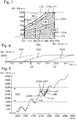
- step c) If it is determined in step c) that the coupled tool unit WE is a thread trimmer FSF or a first cutting blade trimmer FSMkl, in step b) operating data BD in the form of a performance curve PA over time of the drive unit AE or the Operating data BD have been recorded in advance, in particular at a constant speed nA. Furthermore, in step c), a load LT is determined from the recorded power curve PA over the recorded speed curve nA over time.
- step c) it is determined in step c) that the coupled tool unit WE is a thread trimmer FSF if the specific load LT is in a first load range LT1, or is a first cutting blade trimmer FSMkl if the specific load LT is in a second, from the first different load range LT2.
- step d) the drive unit AE is in a thread brushcutter control mode, if the coupled tool unit WE is intended as a thread brushcutter FSF, or a cutting blade brushcutter control mode controlled when the coupled tool unit WE is intended as a first cutting blade brushcutter FSMkl.
- first load range LT1 is higher than the second load range LT2, as in FIG Fig. 7 shown.
- first load range LT1 and the second load range LT2 are delimited by a first boundary line LTG1, in Fig. 7 dashed line, separated from each other.
- an especially thin and continuous base load line of the thread stripper FSF is supported or characterized by the following pairs of values (power PA over speed nA): 236 W over 7500 rpm, 245 W over 7700 rpm, 290 W over 8300 rpm, 335 W over 8800 rpm, 390 W over 9300 rpm, 485 W over 9600rpm.
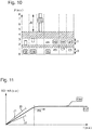
- the thread brushcutter control mode enables a speed limitation to be implemented for operation at a limited speed such as 7700 rpm, as in Fig. 11 shown.
- the cutting blade brushcutter control type enables, but also the other type-dependent control types except for the thread brushcutter control type, to enable operation at a high speed, in particular higher than the limited speed, such as 10000 rpm.
- the criterion load LT can be used to distinguish between the thread trimmer FSF and the first cutting blade trimmer FSMkl.
- step c) If it is determined in step c) that the coupled tool unit WE is a rotary tool unit RWE and that the recorded operating data BD have no dynamic fluctuation and no change at a constant speed nA, the types being one, in particular the blower BG in step b) operating data BD in the form of, in particular the, temporal speed curve nA, one, in particular the temporal current curve IA and one, in particular the temporal power curve PA of the drive unit AE recorded or the operating data BD were previously recorded, in particular the Current curve IA when the speed nA is ramped up and the power curve PA at constant speed nA.
- a mass moment of inertia J is determined from the recorded temporal speed curve nA and the recorded temporal current curve IA.
- a load LT in particular the load LT, is determined from the recorded temporal power curve PA over the recorded temporal rotational speed curve nA.
- the coupled tool unit WE is a blower BG, if that is determined Mass moment of inertia J lies in a, in particular the, first mass moment of inertia range J1 and when the specific load LT lies in a third load range LT3.
- the drive unit is controlled in a blower control mode if the coupled tool unit WE is designated as a blower BG.
- the third load range LT3 is higher than the first load range LT1, as in FIG Fig. 7 shown.
- the third load range LT3 and the first load range LT1 are separated by a second boundary line LTG2, in Fig. 7 dashed line, separated from each other.
- a particularly thick and solid base load line of the blower BG is supported or characterized by the following pairs of values (power PA over speed nA): 110 W over 3500 rpm, 175 W over 4400 rpm, 210 W over 4700 rpm, 235 W over 5050 rpm, 325 W above 5600 rpm, 410 W above 6100 rpm, 520 W above 6650 rpm, 620 W above 7200 rpm, 750 W above 7600 rpm, 950 W above 8200 rpm, 1200 W above 8900 rpm.
- power PA over speed nA 110 W over 3500 rpm, 175 W over 4400 rpm, 210 W over 4700 rpm, 235 W over 5050 rpm, 325 W above 5600 rpm, 410 W above 6100 rpm, 520 W above 6650 rpm, 620 W above 7200 rpm, 750 W above 7600 rpm, 950 W above 8200 rpm, 1
- the criterion mass moment of inertia J and load LT can thus be used to distinguish between blower BG and non-blower.
- the invention provides an advantageous method for operating an electric drive unit which has improved properties, in particular more functionalities, and a system.
- the method and the system or the type-dependent type of control of the drive unit enable the coupled tool unit to be operated optimally and / or to recognize at least one type-specific problem or at least one type-specific problem of the coupled tool unit and thus to solve it or even to avoid it from the outset.
- the type-dependent type of control of the drive unit is made possible by, in particular, indirectly determining the type of the coupled tool unit.
Landscapes
- Life Sciences & Earth Sciences (AREA)
- Environmental Sciences (AREA)
- Engineering & Computer Science (AREA)
- Biodiversity & Conservation Biology (AREA)
- Ecology (AREA)
- Forests & Forestry (AREA)
- Mechanical Engineering (AREA)
- Power Engineering (AREA)
- Soil Sciences (AREA)
- Harvester Elements (AREA)
- Feedback Control In General (AREA)
Claims (12)
- Procédé de fonctionnement, en fonction du type, d'une unité d'entraînement électrique (AE), l'unité d'entraînement (AE) étant conçue pour s'accoupler à une unité d'outil (WE) et l'entraîner, l'unité d'outil (WE) étant sélectionnée parmi un ensemble de différents types d'unités d'outils (WE), l'ensemble comprenant au moins une unité d'outil rotative (RWE) et au moins une unité d'outil non-rotative (NRWE), le procédé comprenant les étapes suivantes :a) entraîner une unité d'outil accouplée (WE) au moyen de l'unité d'entraînement (AE),b) acquérir des données de fonctionnement (BD) de l'unité d'entraînement (AE) pendant l'entraînement,c) déterminer, sur la base des données de fonctionnement acquises (BD), si l'unité d'outil accouplée (WE) est une unité d'outil rotative (RWE) ou une unité d'outil non-rotative (NRWE), etd) commander l'unité d'entraînement (AE) dans un mode de commande en rotation si l'unité d'outil accouplée (WE) est déterminée comme étant une unité d'outil rotative (RWE), ou un mode de commande sans rotation si l'unité d'outil accouplée (WE) est déterminée comme étant une unité d'outil non-rotative (NRWE).
- Procédé selon la revendication 1,- l'étape b) comportant l'acquisition de données de fonctionnement (BD) sous la forme d'une variation temporelle de vitesse de rotation, de courant, de tension et/ou de puissance (nA) de l'unité d'entraînement (AE),- l'étape c) comportant la détermination du fait que l'unité d'outil accouplée (WE) est une unité d'outil rotative (RWE) si la variation temporelle de vitesse de rotation, de courant, de tension et/ou de puissance (nA) qui a été acquise est dépourvue d'oscillation périodique (PDS), ou est une unité d'outil non-rotative (NRWE) si la variation temporelle de vitesse de rotation, de courant, de tension et/ou de puissance (nA) qui a été acquise comporte une oscillation périodique (PDS).
- Procédé selon l'une des revendications précédentes,- s'il est déterminé à l'étape c) que l'unité d'outil accouplée (WE) est une unité d'outil non-rotative (NRWE),- les types comportant une première unité d'outil (HL) présentant un premier rapport de transmission (i1) et une deuxième unité d'outil (SP) présentant un deuxième rapport de transmission (i2) différent du premier,- à l'étape b) les données de fonctionnement (BD) étant acquises sous la forme d'une variation temporelle de vitesse, de courant, de tension et/ou de puissance (nA) de l'unité d'entraînement (AE),- à l'étape c) une fréquence (fSig) d'une oscillation périodique (PDS) et une vitesse de rotation (nA') étant déterminées à partir de la variation temporelle de vitesse de rotation, de courant, de tension et/ou de puissance (nA) qui a été acquise,- un rapport de transmission (i) étant déterminé à partir de la fréquence déterminée (fSig) et de la vitesse déterminée (nA'), et
une détermination étant effectuée du fait que l'unité d'outil accouplée (WE) est une première unité d'outil (HL) si le rapport de transmission déterminé (i) est dans une première plage de rapport de transmission (il), ou une deuxième unité d'outil (SP) si le rapport de transmission déterminé (i) est dans une deuxième plage de rapport de transmission (i2) différente de la première, et- à l'étape d) l'unité d'entraînement (AE) étant commandée dans un premier mode de commande d'outil si l'unité d'outil accouplée (WE) est déterminée comme étant une première unité d'outil (HL), ou dans un deuxième mode de commande d'outil lorsque l'unité d'outil accouplée (WE) est déterminée comme étant une deuxième unité d'outil (SP). - Procédé selon la revendication 3,- la première unité d'outil (HL) étant un taille-haie (HL) et le premier type de commande d'outil étant un type de commande de taille-haie et/ou- la deuxième unité d'outil (SP) étant une récolteuse spéciale et le deuxième type de commande d'outil étant un type de commande de récolteuse spéciale.
- Procédé selon l'une des revendications précédentes,- s'il est déterminé à l'étape c) que l'unité d'outil accouplée (WE) est une unité d'outil rotative (RWE),- les types comportant une scie (HT),- à l'étape b) les données de fonctionnement (BD) étant acquises sous la forme d'une variation temporelle de vitesse de rotation, de courant, de tension et/ou de puissance (PA) de l'unité d'entraînement (AE),- à l'étape c), une détermination étant effectuée du fait que l'unité d'outil accouplée (WE) est une scie (HT) si la variation temporelle de vitesse de rotation, de courant, de tension et/ou de puissance (PA) qui a été acquise comporte une fluctuation dynamique (PLS), et- à l'étape d) l'unité d'entraînement (AE) étant commandée dans un mode de commande de scie si l'unité d'outil accouplée (WE) est déterminée comme étant une scie (HT).
- Procédé selon l'une des revendications précédentes,- s'il est déterminé à l'étape c) que l'unité d'outil accouplée (WE) est une unité d'outil rotative (RWE) et que les données de fonctionnement acquises (BD) ne comportent pas de fluctuation dynamique,- les types comportant une soufflante (BG),- à l'étape b) les données de fonctionnement (BD) étant acquises sous la forme d'une variation temporelle de vitesse de rotation (nA) et d'une variation temporelle de courant, de tension et/ou de puissance (PA) de l'unité d'entraînement (AE),- à l'étape c) une détermination étant effectuée du fait que l'unité d'outil accouplée (WE) n'est pas une soufflante (BG) si la variation temporelle de courant, de tension et/ou de puissance (PA) qui a été acquise présente un changement (PCH) à vitesse de rotation (nA) constante, et- à l'étape d) l'unité d'entraînement (AE) étant commandée dans un mode de commande sans soufflante si l'unité d'outil accouplée (WE) est déterminée comme n'étant pas une soufflante (BG).
- Procédé selon l'une des revendications précédentes,- s'il est déterminé à l'étape c) que l'unité d'outil accouplée (WE) est une unité d'outil rotative (RWE) et que les données de fonctionnement acquises (BD) ne comportent pas de fluctuation dynamique et comportent un changement (PCH) à vitesse constante (nA),- les types comportant une unité d'outil (FCS, FCB, FSB) pourvue d'un arbre d'outil flexible (FAW),- à l'étape b) les données de fonctionnement (BD) étant acquises sous la forme d'une variation temporelle de vitesse (nA) de l'unité d'entraînement (AE),- à l'étape c) une détermination étant effectuée du fait que l'unité d'outil accouplée (WE) est une unité d'outil (FCS, FCB, FSB) pourvue d'un arbre d'outil flexible (FAW) si la variation temporelle de vitesse (nA) acquise dans une plage de vitesse de rotation (DZB) déterminée comporte au moins une sous-oscillation (US), et- à l'étape d) l'unité d'entraînement (AE) étant commandée dans un mode de commande d'arbre flexible si l'unité d'outil accouplée (WE) est déterminée comme étant une unité d'outil (FCS, FCB, FSB) pourvue d'un arbre d'outil flexible (FAW).
- Procédé selon l'une des revendications précédentes,- s'il est déterminé à l'étape c) que l'unité d'outil accouplée (WE) est une unité d'outil rotative (RWE) et que les données de fonctionnement acquises (BD) ne comportent pas de fluctuation dynamique, comportent un changement (PCH) à vitesse constante (nA) et, dans une plage de vitesse de rotation (DZB) déterminée, ne comportent pas de sous-oscillation,- les types comportant une tondeuse à fil (FSF) ou une première tondeuse à lame coupante (FSMkl), une deuxième tondeuse à lame coupante (FSMgr) ou une unité d'outil à guidage au sol (KW, KB, BF),- à l'étape b) les données de fonctionnement (BD) étant acquises sous la forme d'une variation temporelle de vitesse de rotation (nA) et d'une variation temporelle de courant (IA) de l'unité d'entraînement (AE),- à l'étape c), un moment d'inertie de masse (J) étant déterminé à partir de la variation temporelle de vitesse de rotation (nA) acquise et de la variation temporelle de courant (IA) acquise, et une détermination étant effectuée du fait que l'unité d'outil accouplée (WE) est une tondeuse à fil (FSF) ou une première tondeuse à lame coupante (FSMkl) lorsque le moment d'inertie de masse (J) déterminé est dans une première plage de moment d'inertie de masse (Jl), ou une deuxième tondeuse à lame coupante (FSMgr) si le moment d'inertie de masse (J) déterminé est dans une deuxième plage de moment d'inertie de masse (J2) différente de la première, ou une unité d'outil à guidage au sol (KW, KB, BF) si le moment d'inertie de masse (J) déterminé est dans une troisième plage de moment d'inertie de masse (J3) différente de la première et de la deuxième, et- à l'étape d) l'unité d'entraînement (AE) étant commandée dans un premier mode de commande de tondeuse lorsque l'unité d'outil accouplée (WE) est déterminée comme étant une tondeuse à fil (FSF) ou une première tondeuse à lame coupante (FSMkl), ou dans un deuxième type de commande de tondeuse si l'unité d'outil accouplée (WE) est déterminée comme étant une deuxième tondeuse à lame coupante (FSMgr), ou dans un type de commande au sol si l'unité d'outil accouplée (WE) est déterminée comme étant une unité d'outil à guidage au sol (KW, KB, BF).
- Procédé selon la revendication 8,- s'il est déterminé à l'étape c) que l'unité d'outil accouplée (WE) est une tondeuse à fil (FSF) ou une première tondeuse à lame coupante (FSMkl),- à l'étape b) les données de fonctionnement (BD) étant acquises sous la forme d'une variation de puissance (PA) de l'unité d'entraînement (AE),- à l'étape c) une charge (LT) étant déterminée à partir de la variation temporelle de puissance (PA) acquise via la variation temporelle de vitesse de rotation (nA) acquise, et- une détermination étant effectuée du fait que l'unité d'outil accouplée (WE) est une tondeuse à fil (FSF) si la charge (LT) déterminée est dans une première plage de charge (LT1), ou une première tondeuse à lame coupante (FSMkl) si la charge (LT) déterminée est dans une deuxième plage de charge (LT2) différente de la première, et- à l'étape d) l'unité d'entraînement (AE) étant commandée dans un mode de commande de tondeuse à fil si l'unité d'outil accouplée (WE) est déterminée comme étant une tondeuse à fil (FSF), ou dans un mode de commande de tondeuse à lame coupante si l'unité d'outil accouplée (WE) est déterminée comme étant une première tondeuse à lame coupante (FSMkl).
- Procédé selon l'une des revendications précédentes,- s'il est déterminé à l'étape c) que l'unité d'outil accouplée (WE) est une unité d'outil rotative (RWE) et que les données de fonctionnement acquises (BD) ne comportent aucune fluctuation dynamique et aucun changement à vitesse constante (nA),- les types comportant une soufflante (BG),- à l'étape b) les données de fonctionnement (BD) étant acquises sous la forme d'une variation temporelle de vitesse (nA), d'une variation temporelle de courant (IA) et d'une variation temporelle de puissance (PA) de l'unité d'entraînement (AE),- à l'étape c), un moment d'inertie de masse (J) étant déterminé à partir de la variation temporelle (nA) acquise et de la variation temporelle de courant (IA) acquise,
une charge (LT) étant déterminée à partir de la variation temporelle de puissance (PA) acquise via la variation temporelle (nA) acquise, et- une détermination étant effectuée du fait que l'unité d'outil accouplée (WE) est une soufflante (BG) si le moment d'inertie de masse déterminé (J) est dans une première plage de moment d'inertie de masse (J1) et si la charge déterminée (LT) est dans une troisième plage de charge (LT3), et- à l'étape d) l'unité d'entraînement (AE) étant commandée dans un mode de commande de soufflante si l'unité d'outil accouplée (WE) est déterminée comme étant une soufflante (BG). - Système (SY), le système (SY) comportant :- une unité d'entraînement électrique (AE), l'unité d'entraînement (AE) étant conçue pour s'accoupler à une unité d'outil (WE) et l'entraîner, l'unité d'outil (WE) étant sélectionnée parmi un ensemble de différents types d'unités d'outil (WE), l'ensemble comportant au moins une unité d'outil rotative (RWE) et au moins une unité d'outil non-rotative (NRWE),- un dispositif d'acquisition (EE), le dispositif d'acquisition (EE) étant conçu pour acquérir des données de fonctionnement (BD) de l'unité d'entraînement (AE) pendant l'entraînement,- un dispositif de détermination (BE), le dispositif de détermination (BE) étant conçu pour déterminer, sur la base des données de fonctionnement (BD) acquises, si l'unité d'outil accouplée (WE) est une unité d'outil rotative (RWE) ou une unité d'outil non-rotative (NRWE), et- un dispositif de commande (SE), le dispositif de commande (SE) étant conçu pour commander l'unité d'entraînement (AE) dans un mode de commande en rotation si l'unité d'outil accouplée (WE) est déterminée comme une unité d'outil rotative (RWE), ou un mode de commande sans rotation si l'unité d'outil accouplée (WE) est déterminée comme une unité d'outil non-rotative (NRWE).
- Système (SY) selon la revendication 11, dans lequel le système (SY) comprend :- au moins une unité d'outil (WE), qui est conçue pour l'accouplement et l'entraînement par le biais de l'unité d'entraînement (AE).
Priority Applications (4)
| Application Number | Priority Date | Filing Date | Title |
|---|---|---|---|
| EP18160652.6A EP3536461B1 (fr) | 2018-03-08 | 2018-03-08 | Procédé de fonctionnement dépendant du type d'une unité d'entraînement électrique et système |
| ES18160652T ES2855140T3 (es) | 2018-03-08 | 2018-03-08 | Procedimiento para la operación dependiente del tipo, de una unidad eléctrica de accionamiento y un sistema |
| US16/295,128 US10630227B2 (en) | 2018-03-08 | 2019-03-07 | Method for type-specific operating of an electric drive unit and system |
| CN201910175825.XA CN110235627B (zh) | 2018-03-08 | 2019-03-08 | 用于随类型而定来运行电驱动单元的方法和系统 |
Applications Claiming Priority (1)
| Application Number | Priority Date | Filing Date | Title |
|---|---|---|---|
| EP18160652.6A EP3536461B1 (fr) | 2018-03-08 | 2018-03-08 | Procédé de fonctionnement dépendant du type d'une unité d'entraînement électrique et système |
Publications (2)
| Publication Number | Publication Date |
|---|---|
| EP3536461A1 EP3536461A1 (fr) | 2019-09-11 |
| EP3536461B1 true EP3536461B1 (fr) | 2020-11-25 |
Family
ID=61599028
Family Applications (1)
| Application Number | Title | Priority Date | Filing Date |
|---|---|---|---|
| EP18160652.6A Active EP3536461B1 (fr) | 2018-03-08 | 2018-03-08 | Procédé de fonctionnement dépendant du type d'une unité d'entraînement électrique et système |
Country Status (4)
| Country | Link |
|---|---|
| US (1) | US10630227B2 (fr) |
| EP (1) | EP3536461B1 (fr) |
| CN (1) | CN110235627B (fr) |
| ES (1) | ES2855140T3 (fr) |
Families Citing this family (8)
| Publication number | Priority date | Publication date | Assignee | Title |
|---|---|---|---|---|
| JP7281917B2 (ja) * | 2019-02-18 | 2023-05-26 | 株式会社マキタ | 電動作業機 |
| JP7224950B2 (ja) * | 2019-02-18 | 2023-02-20 | 株式会社マキタ | 電動作業機 |
| JP7209597B2 (ja) * | 2019-07-18 | 2023-01-20 | 株式会社マキタ | 電動作業機 |
| EP4009764A1 (fr) * | 2019-08-05 | 2022-06-15 | Husqvarna Ab | Détection d'outil dans des outils électriques portatifs |
| US11844309B2 (en) * | 2020-06-02 | 2023-12-19 | Douglas Franklin | String trimmer having a curved shaft section for variable length and operator height |
| US11787033B2 (en) * | 2021-05-04 | 2023-10-17 | Nick Semitka | Multifunctional reciprocating utility device |
| EP4101595A1 (fr) * | 2021-06-11 | 2022-12-14 | Hilti Aktiengesellschaft | Procédé de détermination d'une propriété d'un outil, ainsi que machine-outil mobile |
| EP4272894A1 (fr) | 2022-05-06 | 2023-11-08 | Hilti Aktiengesellschaft | Procédé permettant de faire fonctionner une machine-outil et machine-outil |
Family Cites Families (26)
| Publication number | Priority date | Publication date | Assignee | Title |
|---|---|---|---|---|
| US6536536B1 (en) * | 1999-04-29 | 2003-03-25 | Stephen F. Gass | Power tools |
| WO2001027435A1 (fr) * | 1999-10-13 | 2001-04-19 | Baker Hughes Incorporated | Appareil permettant le transfert d'energie electrique entre les elements rotatifs et non rotatifs des outils fond de trou |
| DE19960824C2 (de) | 1999-12-16 | 2003-08-21 | Hilti Ag | Verfahren und Einrichtung zur Untersuchung und Identifizierung der Art eines Untergrunds |
| GB2392966B (en) * | 2002-09-13 | 2006-05-31 | Black & Decker Inc | Rotary tool with overload clutch |
| DE602006020699D1 (de) * | 2006-06-01 | 2011-04-28 | Wila Bv | Auswechselbares Werkzeug/Manipulator Kombination |
| JP4787768B2 (ja) | 2007-02-05 | 2011-10-05 | 日東工器株式会社 | ドリル装置 |
| DE102007056319A1 (de) | 2007-11-22 | 2009-05-28 | Andreas Stihl Ag & Co. Kg | Werkzeugkopf mit elektromechanischer Abspuleinrichtung |
| DE102009045942A1 (de) * | 2009-10-23 | 2011-04-28 | Robert Bosch Gmbh | Handgehaltene Elektrowerkzeugmaschine |
| DE102009047348A1 (de) * | 2009-12-01 | 2011-06-09 | Robert Bosch Gmbh | Gartengerät mit mindestens einer Arbeitsklinge |
| WO2011085194A1 (fr) * | 2010-01-07 | 2011-07-14 | Black & Decker Inc. | Tournevis motorisé possédant une commande d'entrée rotative |
| DE102010006549A1 (de) * | 2010-02-01 | 2011-08-04 | Dürr Dental AG, 74321 | Arbeitsgerät mit wechselbarem Arbeitskopf |
| US8674640B2 (en) * | 2011-01-05 | 2014-03-18 | Makita Corporation | Electric power tool |
| ITPD20110144A1 (it) * | 2011-05-06 | 2012-11-07 | Zanon S R L | Apparecchiatura portatile per l'alimentazione e il controllo di attrezzi elettrici, particolarmente per uso agricolo |
| ITRM20110276A1 (it) * | 2011-06-03 | 2012-12-04 | Vilde Nardicchia | Sistema di identificazione di oggetti e di controllo di mezzi di azionamento degli stessi. |
| DE102011104901B4 (de) | 2011-06-16 | 2018-04-12 | C. & E. Fein Gmbh | Kraftgetriebene Handwerkzeugmaschine |
| EP2895301A2 (fr) | 2012-09-11 | 2015-07-22 | Black & Decker, Inc. | Système et procédé pour identifier un outil électrique |
| US9367062B2 (en) | 2012-12-31 | 2016-06-14 | Robert Bosch Gmbh | System and method for operational data retrieval from a power tool |
| JP6002643B2 (ja) * | 2013-09-06 | 2016-10-05 | 株式会社日立産機システム | 制御装置およびそれを用いた交流電動機システム |
| DE102014209009A1 (de) | 2014-01-27 | 2015-07-30 | Robert Bosch Gmbh | Werkzeugmaschinenvorrichtung |
| DE102014208980A1 (de) | 2014-01-27 | 2015-07-30 | Robert Bosch Gmbh | Werkzeugmaschinenvorrichtung |
| DE102014209032A1 (de) | 2014-01-27 | 2015-07-30 | Robert Bosch Gmbh | Werkzeugmaschinenvorrichtung |
| US9987043B2 (en) * | 2014-10-24 | 2018-06-05 | Stryker European Holdings I, Llc | Methods and systems for adjusting an external fixation frame |
| DE202014009989U1 (de) * | 2014-12-17 | 2015-01-16 | Robert Bosch Gmbh | Oszillationswerkzeugmaschine |
| CA3059599A1 (fr) * | 2015-02-06 | 2016-08-11 | Mtd Products Inc | Outil d'entretien de gazon portable |
| CN107426964B (zh) | 2015-03-26 | 2020-02-11 | 胡斯华纳有限公司 | 带有自检能力的双向修剪机 |
| FR3039087B1 (fr) * | 2015-07-22 | 2018-03-09 | Innovation Fabrication Commercialisation Infaco | Outil electroportatif multifonctions |
-
2018
- 2018-03-08 EP EP18160652.6A patent/EP3536461B1/fr active Active
- 2018-03-08 ES ES18160652T patent/ES2855140T3/es active Active
-
2019
- 2019-03-07 US US16/295,128 patent/US10630227B2/en active Active
- 2019-03-08 CN CN201910175825.XA patent/CN110235627B/zh active Active
Non-Patent Citations (1)
| Title |
|---|
| None * |
Also Published As
| Publication number | Publication date |
|---|---|
| EP3536461A1 (fr) | 2019-09-11 |
| US10630227B2 (en) | 2020-04-21 |
| ES2855140T3 (es) | 2021-09-23 |
| US20190280639A1 (en) | 2019-09-12 |
| CN110235627A (zh) | 2019-09-17 |
| CN110235627B (zh) | 2022-05-17 |
Similar Documents
| Publication | Publication Date | Title |
|---|---|---|
| EP3536461B1 (fr) | Procédé de fonctionnement dépendant du type d'une unité d'entraînement électrique et système | |
| EP3298876B1 (fr) | Ramasseuse-hacheuse | |
| EP1935228B1 (fr) | Agencement d'entraînement pour un appareil de travail portable | |
| EP3014975B1 (fr) | Dispositif d'outil de jardinage et son procede de fonctionnement | |
| DE102009054116B4 (de) | Arbeitsgerät mit Verbrennungsmotor | |
| DE19631555A1 (de) | Elektrischer Rasenmäher | |
| DE3505887A1 (de) | Verfahren und einrichtung zur regelung und darstellung der geschwindigkeit und der maschinenbelastung einer mobilen haeckselmaschine | |
| DE102012002270A1 (de) | Verfahren zum Betrieb eines Arbeitsgerätes mit einem Elektromotor und Arbeitsgerät mit einem Elektromotor | |
| EP2637299B1 (fr) | Outil de travail doté d'un moteur d'entraînement électrique | |
| EP2112357A2 (fr) | Procédé de fonctionnement pour un moteur à combustion | |
| DE102008036378A1 (de) | Landwirtschaftliche Erntemaschine | |
| EP1902609B1 (fr) | Procédé destiné à la commande d'un dispositif d'affichage dans une moissonneuse | |
| WO2013034345A1 (fr) | Engin de travail autonome | |
| EP2434133A1 (fr) | Concept de commande d'un moteur et dispositif de commande de puissance d'un véhicule motorisé | |
| EP2857246B1 (fr) | Machine agricole | |
| DE102019213294A1 (de) | Angetriebene Bodenpflegevorrichtung | |
| EP3815509B1 (fr) | Appareil portatif de traitement du jardin, de la forêt et / ou de la construction et procédé pour un appareil portatif de traitement du jardin, de la forêt et / ou de la construction | |
| EP3604778B1 (fr) | Procédé de démarrage d'un moteur à combustion interne | |
| DE102014226742A1 (de) | Gartengerätevorrichtung und Verfahren zu deren Betrieb | |
| DE102020103708A1 (de) | Elektrische arbeitsmaschine | |
| DE3029056A1 (de) | Fadenschneider fuer rasenkanten u.dgl. | |
| EP3881992A1 (fr) | Appareil de travaux de jardinage, de foresterie et/ou de construction guidé à la main et procédé de fonctionnement d'un appareil de travaux de jardinage, de foresterie et/ou de construction guidé à la main | |
| DE102017127843A1 (de) | Elektrische Arbeitsmaschine | |
| DE102007015991A1 (de) | Handgeführtes Arbeitsgerät, insbesondere Freischneider oder dgl. mit einem elektrischen Antriebsmotor | |
| DE4100611A1 (de) | Regeleinrichtung zur regelung der motordrehzahl und der schneidefadennachfuehrung eines rasentrimmers |
Legal Events
| Date | Code | Title | Description |
|---|---|---|---|
| PUAI | Public reference made under article 153(3) epc to a published international application that has entered the european phase |
Free format text: ORIGINAL CODE: 0009012 |
|
| STAA | Information on the status of an ep patent application or granted ep patent |
Free format text: STATUS: THE APPLICATION HAS BEEN PUBLISHED |
|
| AK | Designated contracting states |
Kind code of ref document: A1 Designated state(s): AL AT BE BG CH CY CZ DE DK EE ES FI FR GB GR HR HU IE IS IT LI LT LU LV MC MK MT NL NO PL PT RO RS SE SI SK SM TR |
|
| AX | Request for extension of the european patent |
Extension state: BA ME |
|
| STAA | Information on the status of an ep patent application or granted ep patent |
Free format text: STATUS: REQUEST FOR EXAMINATION WAS MADE |
|
| 17P | Request for examination filed |
Effective date: 20200121 |
|
| RBV | Designated contracting states (corrected) |
Designated state(s): AL AT BE BG CH CY CZ DE DK EE ES FI FR GB GR HR HU IE IS IT LI LT LU LV MC MK MT NL NO PL PT RO RS SE SI SK SM TR |
|
| GRAP | Despatch of communication of intention to grant a patent |
Free format text: ORIGINAL CODE: EPIDOSNIGR1 |
|
| STAA | Information on the status of an ep patent application or granted ep patent |
Free format text: STATUS: GRANT OF PATENT IS INTENDED |
|
| RIC1 | Information provided on ipc code assigned before grant |
Ipc: B25F 3/00 20060101AFI20200625BHEP Ipc: B25F 5/00 20060101ALI20200625BHEP |
|
| INTG | Intention to grant announced |
Effective date: 20200716 |
|
| GRAS | Grant fee paid |
Free format text: ORIGINAL CODE: EPIDOSNIGR3 |
|
| GRAA | (expected) grant |
Free format text: ORIGINAL CODE: 0009210 |
|
| STAA | Information on the status of an ep patent application or granted ep patent |
Free format text: STATUS: THE PATENT HAS BEEN GRANTED |
|
| AK | Designated contracting states |
Kind code of ref document: B1 Designated state(s): AL AT BE BG CH CY CZ DE DK EE ES FI FR GB GR HR HU IE IS IT LI LT LU LV MC MK MT NL NO PL PT RO RS SE SI SK SM TR |
|
| REG | Reference to a national code |
Ref country code: GB Ref legal event code: FG4D Free format text: NOT ENGLISH |
|
| REG | Reference to a national code |
Ref country code: CH Ref legal event code: EP |
|
| REG | Reference to a national code |
Ref country code: DE Ref legal event code: R096 Ref document number: 502018003083 Country of ref document: DE |
|
| REG | Reference to a national code |
Ref country code: AT Ref legal event code: REF Ref document number: 1337749 Country of ref document: AT Kind code of ref document: T Effective date: 20201215 |
|
| REG | Reference to a national code |
Ref country code: IE Ref legal event code: FG4D Free format text: LANGUAGE OF EP DOCUMENT: GERMAN |
|
| REG | Reference to a national code |
Ref country code: NL Ref legal event code: MP Effective date: 20201125 |
|
| PG25 | Lapsed in a contracting state [announced via postgrant information from national office to epo] |
Ref country code: RS Free format text: LAPSE BECAUSE OF FAILURE TO SUBMIT A TRANSLATION OF THE DESCRIPTION OR TO PAY THE FEE WITHIN THE PRESCRIBED TIME-LIMIT Effective date: 20201125 Ref country code: PT Free format text: LAPSE BECAUSE OF FAILURE TO SUBMIT A TRANSLATION OF THE DESCRIPTION OR TO PAY THE FEE WITHIN THE PRESCRIBED TIME-LIMIT Effective date: 20210325 Ref country code: FI Free format text: LAPSE BECAUSE OF FAILURE TO SUBMIT A TRANSLATION OF THE DESCRIPTION OR TO PAY THE FEE WITHIN THE PRESCRIBED TIME-LIMIT Effective date: 20201125 Ref country code: NO Free format text: LAPSE BECAUSE OF FAILURE TO SUBMIT A TRANSLATION OF THE DESCRIPTION OR TO PAY THE FEE WITHIN THE PRESCRIBED TIME-LIMIT Effective date: 20210225 Ref country code: GR Free format text: LAPSE BECAUSE OF FAILURE TO SUBMIT A TRANSLATION OF THE DESCRIPTION OR TO PAY THE FEE WITHIN THE PRESCRIBED TIME-LIMIT Effective date: 20210226 |
|
| PG25 | Lapsed in a contracting state [announced via postgrant information from national office to epo] |
Ref country code: BG Free format text: LAPSE BECAUSE OF FAILURE TO SUBMIT A TRANSLATION OF THE DESCRIPTION OR TO PAY THE FEE WITHIN THE PRESCRIBED TIME-LIMIT Effective date: 20210225 Ref country code: LV Free format text: LAPSE BECAUSE OF FAILURE TO SUBMIT A TRANSLATION OF THE DESCRIPTION OR TO PAY THE FEE WITHIN THE PRESCRIBED TIME-LIMIT Effective date: 20201125 Ref country code: IS Free format text: LAPSE BECAUSE OF FAILURE TO SUBMIT A TRANSLATION OF THE DESCRIPTION OR TO PAY THE FEE WITHIN THE PRESCRIBED TIME-LIMIT Effective date: 20210325 Ref country code: PL Free format text: LAPSE BECAUSE OF FAILURE TO SUBMIT A TRANSLATION OF THE DESCRIPTION OR TO PAY THE FEE WITHIN THE PRESCRIBED TIME-LIMIT Effective date: 20201125 Ref country code: SE Free format text: LAPSE BECAUSE OF FAILURE TO SUBMIT A TRANSLATION OF THE DESCRIPTION OR TO PAY THE FEE WITHIN THE PRESCRIBED TIME-LIMIT Effective date: 20201125 |
|
| REG | Reference to a national code |
Ref country code: LT Ref legal event code: MG9D |
|
| PG25 | Lapsed in a contracting state [announced via postgrant information from national office to epo] |
Ref country code: HR Free format text: LAPSE BECAUSE OF FAILURE TO SUBMIT A TRANSLATION OF THE DESCRIPTION OR TO PAY THE FEE WITHIN THE PRESCRIBED TIME-LIMIT Effective date: 20201125 |
|
| PG25 | Lapsed in a contracting state [announced via postgrant information from national office to epo] |
Ref country code: RO Free format text: LAPSE BECAUSE OF FAILURE TO SUBMIT A TRANSLATION OF THE DESCRIPTION OR TO PAY THE FEE WITHIN THE PRESCRIBED TIME-LIMIT Effective date: 20201125 Ref country code: SK Free format text: LAPSE BECAUSE OF FAILURE TO SUBMIT A TRANSLATION OF THE DESCRIPTION OR TO PAY THE FEE WITHIN THE PRESCRIBED TIME-LIMIT Effective date: 20201125 Ref country code: LT Free format text: LAPSE BECAUSE OF FAILURE TO SUBMIT A TRANSLATION OF THE DESCRIPTION OR TO PAY THE FEE WITHIN THE PRESCRIBED TIME-LIMIT Effective date: 20201125 Ref country code: CZ Free format text: LAPSE BECAUSE OF FAILURE TO SUBMIT A TRANSLATION OF THE DESCRIPTION OR TO PAY THE FEE WITHIN THE PRESCRIBED TIME-LIMIT Effective date: 20201125 Ref country code: EE Free format text: LAPSE BECAUSE OF FAILURE TO SUBMIT A TRANSLATION OF THE DESCRIPTION OR TO PAY THE FEE WITHIN THE PRESCRIBED TIME-LIMIT Effective date: 20201125 Ref country code: SM Free format text: LAPSE BECAUSE OF FAILURE TO SUBMIT A TRANSLATION OF THE DESCRIPTION OR TO PAY THE FEE WITHIN THE PRESCRIBED TIME-LIMIT Effective date: 20201125 |
|
| REG | Reference to a national code |
Ref country code: DE Ref legal event code: R097 Ref document number: 502018003083 Country of ref document: DE |
|
| PG25 | Lapsed in a contracting state [announced via postgrant information from national office to epo] |
Ref country code: DK Free format text: LAPSE BECAUSE OF FAILURE TO SUBMIT A TRANSLATION OF THE DESCRIPTION OR TO PAY THE FEE WITHIN THE PRESCRIBED TIME-LIMIT Effective date: 20201125 |
|
| REG | Reference to a national code |
Ref country code: ES Ref legal event code: FG2A Ref document number: 2855140 Country of ref document: ES Kind code of ref document: T3 Effective date: 20210923 |
|
| PLBE | No opposition filed within time limit |
Free format text: ORIGINAL CODE: 0009261 |
|
| STAA | Information on the status of an ep patent application or granted ep patent |
Free format text: STATUS: NO OPPOSITION FILED WITHIN TIME LIMIT |
|
| PG25 | Lapsed in a contracting state [announced via postgrant information from national office to epo] |
Ref country code: NL Free format text: LAPSE BECAUSE OF FAILURE TO SUBMIT A TRANSLATION OF THE DESCRIPTION OR TO PAY THE FEE WITHIN THE PRESCRIBED TIME-LIMIT Effective date: 20201125 Ref country code: AL Free format text: LAPSE BECAUSE OF FAILURE TO SUBMIT A TRANSLATION OF THE DESCRIPTION OR TO PAY THE FEE WITHIN THE PRESCRIBED TIME-LIMIT Effective date: 20201125 Ref country code: IT Free format text: LAPSE BECAUSE OF FAILURE TO SUBMIT A TRANSLATION OF THE DESCRIPTION OR TO PAY THE FEE WITHIN THE PRESCRIBED TIME-LIMIT Effective date: 20201125 Ref country code: MC Free format text: LAPSE BECAUSE OF FAILURE TO SUBMIT A TRANSLATION OF THE DESCRIPTION OR TO PAY THE FEE WITHIN THE PRESCRIBED TIME-LIMIT Effective date: 20201125 |
|
| REG | Reference to a national code |
Ref country code: CH Ref legal event code: PL |
|
| 26N | No opposition filed |
Effective date: 20210826 |
|
| PG25 | Lapsed in a contracting state [announced via postgrant information from national office to epo] |
Ref country code: SI Free format text: LAPSE BECAUSE OF FAILURE TO SUBMIT A TRANSLATION OF THE DESCRIPTION OR TO PAY THE FEE WITHIN THE PRESCRIBED TIME-LIMIT Effective date: 20201125 |
|
| REG | Reference to a national code |
Ref country code: BE Ref legal event code: MM Effective date: 20210331 |
|
| PG25 | Lapsed in a contracting state [announced via postgrant information from national office to epo] |
Ref country code: CH Free format text: LAPSE BECAUSE OF NON-PAYMENT OF DUE FEES Effective date: 20210331 Ref country code: LI Free format text: LAPSE BECAUSE OF NON-PAYMENT OF DUE FEES Effective date: 20210331 Ref country code: LU Free format text: LAPSE BECAUSE OF NON-PAYMENT OF DUE FEES Effective date: 20210308 Ref country code: IE Free format text: LAPSE BECAUSE OF NON-PAYMENT OF DUE FEES Effective date: 20210308 |
|
| PG25 | Lapsed in a contracting state [announced via postgrant information from national office to epo] |
Ref country code: IS Free format text: LAPSE BECAUSE OF FAILURE TO SUBMIT A TRANSLATION OF THE DESCRIPTION OR TO PAY THE FEE WITHIN THE PRESCRIBED TIME-LIMIT Effective date: 20210325 |
|
| PG25 | Lapsed in a contracting state [announced via postgrant information from national office to epo] |
Ref country code: BE Free format text: LAPSE BECAUSE OF NON-PAYMENT OF DUE FEES Effective date: 20210331 |
|
| PGFP | Annual fee paid to national office [announced via postgrant information from national office to epo] |
Ref country code: GB Payment date: 20230321 Year of fee payment: 6 |
|
| PG25 | Lapsed in a contracting state [announced via postgrant information from national office to epo] |
Ref country code: CY Free format text: LAPSE BECAUSE OF FAILURE TO SUBMIT A TRANSLATION OF THE DESCRIPTION OR TO PAY THE FEE WITHIN THE PRESCRIBED TIME-LIMIT Effective date: 20201125 |
|
| PG25 | Lapsed in a contracting state [announced via postgrant information from national office to epo] |
Ref country code: HU Free format text: LAPSE BECAUSE OF FAILURE TO SUBMIT A TRANSLATION OF THE DESCRIPTION OR TO PAY THE FEE WITHIN THE PRESCRIBED TIME-LIMIT; INVALID AB INITIO Effective date: 20180308 |
|
| PGFP | Annual fee paid to national office [announced via postgrant information from national office to epo] |
Ref country code: ES Payment date: 20230424 Year of fee payment: 6 |
|
| PG25 | Lapsed in a contracting state [announced via postgrant information from national office to epo] |
Ref country code: MK Free format text: LAPSE BECAUSE OF FAILURE TO SUBMIT A TRANSLATION OF THE DESCRIPTION OR TO PAY THE FEE WITHIN THE PRESCRIBED TIME-LIMIT Effective date: 20201125 |
|
| PGFP | Annual fee paid to national office [announced via postgrant information from national office to epo] |
Ref country code: DE Payment date: 20240328 Year of fee payment: 7 |
|
| REG | Reference to a national code |
Ref country code: AT Ref legal event code: MM01 Ref document number: 1337749 Country of ref document: AT Kind code of ref document: T Effective date: 20230308 |
|
| PGFP | Annual fee paid to national office [announced via postgrant information from national office to epo] |
Ref country code: FR Payment date: 20240327 Year of fee payment: 7 |
|
| PG25 | Lapsed in a contracting state [announced via postgrant information from national office to epo] |
Ref country code: TR Free format text: LAPSE BECAUSE OF FAILURE TO SUBMIT A TRANSLATION OF THE DESCRIPTION OR TO PAY THE FEE WITHIN THE PRESCRIBED TIME-LIMIT Effective date: 20201125 |
|
| PG25 | Lapsed in a contracting state [announced via postgrant information from national office to epo] |
Ref country code: AT Free format text: LAPSE BECAUSE OF NON-PAYMENT OF DUE FEES Effective date: 20230308 |
|
| PG25 | Lapsed in a contracting state [announced via postgrant information from national office to epo] |
Ref country code: AT Free format text: LAPSE BECAUSE OF NON-PAYMENT OF DUE FEES Effective date: 20230308 |