EP3043053B1 - System und verfahren zur erkennung von hubkolbenvorrichtungsanomalitäten mit standardqualitätskontrolltechniken - Google Patents
System und verfahren zur erkennung von hubkolbenvorrichtungsanomalitäten mit standardqualitätskontrolltechniken Download PDFInfo
- Publication number
- EP3043053B1 EP3043053B1 EP16150238.0A EP16150238A EP3043053B1 EP 3043053 B1 EP3043053 B1 EP 3043053B1 EP 16150238 A EP16150238 A EP 16150238A EP 3043053 B1 EP3043053 B1 EP 3043053B1
- Authority
- EP
- European Patent Office
- Prior art keywords
- signal
- spectral
- reciprocating device
- sigma
- engine
- Prior art date
- Legal status (The legal status is an assumption and is not a legal conclusion. Google has not performed a legal analysis and makes no representation as to the accuracy of the status listed.)
- Active
Links
Images


Classifications
-
- F—MECHANICAL ENGINEERING; LIGHTING; HEATING; WEAPONS; BLASTING
- F02—COMBUSTION ENGINES; HOT-GAS OR COMBUSTION-PRODUCT ENGINE PLANTS
- F02D—CONTROLLING COMBUSTION ENGINES
- F02D35/00—Controlling engines, dependent on conditions exterior or interior to engines, not otherwise provided for
- F02D35/02—Controlling engines, dependent on conditions exterior or interior to engines, not otherwise provided for on interior conditions
- F02D35/027—Controlling engines, dependent on conditions exterior or interior to engines, not otherwise provided for on interior conditions using knock sensors
-
- F—MECHANICAL ENGINEERING; LIGHTING; HEATING; WEAPONS; BLASTING
- F02—COMBUSTION ENGINES; HOT-GAS OR COMBUSTION-PRODUCT ENGINE PLANTS
- F02D—CONTROLLING COMBUSTION ENGINES
- F02D41/00—Electrical control of supply of combustible mixture or its constituents
- F02D41/22—Safety or indicating devices for abnormal conditions
-
- G—PHYSICS
- G01—MEASURING; TESTING
- G01L—MEASURING FORCE, STRESS, TORQUE, WORK, MECHANICAL POWER, MECHANICAL EFFICIENCY, OR FLUID PRESSURE
- G01L23/00—Devices or apparatus for measuring or indicating or recording rapid changes, such as oscillations, in the pressure of steam, gas, or liquid; Indicators for determining work or energy of steam, internal-combustion, or other fluid-pressure engines from the condition of the working fluid
- G01L23/22—Devices or apparatus for measuring or indicating or recording rapid changes, such as oscillations, in the pressure of steam, gas, or liquid; Indicators for determining work or energy of steam, internal-combustion, or other fluid-pressure engines from the condition of the working fluid for detecting or indicating knocks in internal-combustion engines; Units comprising pressure-sensitive members combined with ignitors for firing internal-combustion engines
- G01L23/221—Devices or apparatus for measuring or indicating or recording rapid changes, such as oscillations, in the pressure of steam, gas, or liquid; Indicators for determining work or energy of steam, internal-combustion, or other fluid-pressure engines from the condition of the working fluid for detecting or indicating knocks in internal-combustion engines; Units comprising pressure-sensitive members combined with ignitors for firing internal-combustion engines for detecting or indicating knocks in internal combustion engines
-
- G—PHYSICS
- G01—MEASURING; TESTING
- G01M—TESTING STATIC OR DYNAMIC BALANCE OF MACHINES OR STRUCTURES; TESTING OF STRUCTURES OR APPARATUS, NOT OTHERWISE PROVIDED FOR
- G01M15/00—Testing of engines
- G01M15/04—Testing internal-combustion engines
- G01M15/042—Testing internal-combustion engines by monitoring a single specific parameter not covered by groups G01M15/06 - G01M15/12
-
- F—MECHANICAL ENGINEERING; LIGHTING; HEATING; WEAPONS; BLASTING
- F02—COMBUSTION ENGINES; HOT-GAS OR COMBUSTION-PRODUCT ENGINE PLANTS
- F02D—CONTROLLING COMBUSTION ENGINES
- F02D41/00—Electrical control of supply of combustible mixture or its constituents
- F02D41/24—Electrical control of supply of combustible mixture or its constituents characterised by the use of digital means
- F02D41/26—Electrical control of supply of combustible mixture or its constituents characterised by the use of digital means using computer, e.g. microprocessor
- F02D41/28—Interface circuits
- F02D2041/286—Interface circuits comprising means for signal processing
- F02D2041/288—Interface circuits comprising means for signal processing for performing a transformation into the frequency domain, e.g. Fourier transformation
-
- Y—GENERAL TAGGING OF NEW TECHNOLOGICAL DEVELOPMENTS; GENERAL TAGGING OF CROSS-SECTIONAL TECHNOLOGIES SPANNING OVER SEVERAL SECTIONS OF THE IPC; TECHNICAL SUBJECTS COVERED BY FORMER USPC CROSS-REFERENCE ART COLLECTIONS [XRACs] AND DIGESTS
- Y02—TECHNOLOGIES OR APPLICATIONS FOR MITIGATION OR ADAPTATION AGAINST CLIMATE CHANGE
- Y02T—CLIMATE CHANGE MITIGATION TECHNOLOGIES RELATED TO TRANSPORTATION
- Y02T10/00—Road transport of goods or passengers
- Y02T10/10—Internal combustion engine [ICE] based vehicles
- Y02T10/30—Use of alternative fuels, e.g. biofuels
-
- Y—GENERAL TAGGING OF NEW TECHNOLOGICAL DEVELOPMENTS; GENERAL TAGGING OF CROSS-SECTIONAL TECHNOLOGIES SPANNING OVER SEVERAL SECTIONS OF THE IPC; TECHNICAL SUBJECTS COVERED BY FORMER USPC CROSS-REFERENCE ART COLLECTIONS [XRACs] AND DIGESTS
- Y02—TECHNOLOGIES OR APPLICATIONS FOR MITIGATION OR ADAPTATION AGAINST CLIMATE CHANGE
- Y02T—CLIMATE CHANGE MITIGATION TECHNOLOGIES RELATED TO TRANSPORTATION
- Y02T10/00—Road transport of goods or passengers
- Y02T10/10—Internal combustion engine [ICE] based vehicles
- Y02T10/40—Engine management systems
Definitions
- US 2009/276147 discloses a knock diagnostic module having a knock module that increments a sample count when a cylinder firing signal corresponding to a first cylinder is received and selectively increments a knock count based on a knock detection signal that corresponds to the cylinder firing signal of the first cylinder
- a knock analysis module analyzes the knock count of the first cylinder when the sample count of the first cylinder reaches a predetermined value and selectively generates an excessive knock signal when the knock count exceeds a predetermined threshold.
- a remedial action module selectively performs a remedial action based on the excessive knock signal.
- a method and system are provided for diagnosing the health-condition of engines, in particular internal combustion reciprocating engines, in which the harmonic terms of the Fourier series representation of the engine vibration are correlated with the mechanical state of the engine.
- the characteristics of the harmonic components of the Fourier representation are monitored at one or more predetermined frequencies according to at least one first predetermined criterion, and the characteristics of these harmonic components are analysed according to at least one second predetermined criterion to determine the operational state of the engine correlated to the second criterion.
- the present invention relates to a system and method as set forth in the claims.
- FIG. 2 is a side cross-sectional view of an embodiment of a piston assembly 25 having a piston 20 disposed within a cylinder 26 (e.g., an engine cylinder) of the reciprocating engine 10.
- the cylinder 26 has an inner annular wall 28 defining a cylindrical cavity 30 (e.g., bore).
- the piston 20 may be defined by an axial axis or direction 34, a radial axis or direction 36, and a circumferential axis or direction 38.
- the piston 20 includes a top portion 40 (e.g., a top land).
- the top portion 40 generally blocks the fuel 18 and the air 16, or a fuel-air mixture 32, from escaping from the combustion chamber 12 during reciprocating motion of the piston 20.
- the memory 74 may store non-transitory code or computer instructions that may be executed by the processor 72.
- the ECU 25 monitors and controls and operation of the engine 10, for example, by adjusting combustion timing, valve 62, 64, timing, adjusting the delivery of fuel and oxidant (e.g., air), and so on.
- fuel and oxidant e.g., air
- the indicators may be color coated to indicate the severity of the trend (e.g., red for a 3- ⁇ deviation from a baseline, yellow or orange for a 2- ⁇ deviation from a baseline, etc.).
- Multiple control charts and/or graphical features may be generated for the different events described above.
- the process 90 further includes monitoring engine health utilizing SQC techniques such as SQC charting statistics (block 106) (e.g., to enable statistical process control).
- Monitoring engine health may include monitoring changes in real time (i.e., controlling the engine by receiving and processing the data from the knock sensors 23 and returning the results sufficiently quickly to affect the engine at that time) in the specific spectral bins or buckets to enable performance of diagnostics or advanced prognostics.
- the process 90 also includes providing an indication of the potential issue with the engine (block 112).
- This may include providing a warning (e.g., warning flag) that certain frequency bands (i.e., spectral bins) are trending toward non-Gaussian behavior (e.g., deviation of 2- ⁇ but less than 3- ⁇ relative to a baseline).
- the warnings may include providing visual or textual warnings on a display coupled to the ECU 25 or on a remote device associated via a network (e.g., controller area network) with the ECU 25.
- Providing indications of the potential issue with the engine may also include displaying control charts generated utilizing the SQC charting techniques as well as other graphical features (e.g., histograms).
- FIG. 5 is a flow chart illustrating an embodiment of a process 122 for monitoring engine health (e.g., the engine 10 in FIG. 2 ) utilizing FFT, PSD, and different sigma ( ⁇ ) threshold levels.
- a similar process may be utilized in monitoring health of a reciprocating device (e.g., compressor).
- the process 122 may be implemented as computer instructions or executable code stored in the memory 74 and executable by the processor 72 of the ECU 25 or reciprocating device controller.
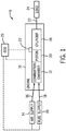
- the process 122 includes receiving one or more signals from one or more knock sensors 23 coupled to the engine 10 (block 124), sampling the one or more signals received from the one or more knock sensors 23 (block 126), and processing the sampled signals (block 128) as described above in FIG. 4 .
- the process 122 includes applying a FFT to generate Fourier transformed signals (block 130) and obtaining or generating a PSD for each of the Fourier transformed signals (block 132) as described above in FIG. 4 .
- the process 122 includes determining if the specific bins or buckets deviate from their respective baselines at or beyond the respective 3- ⁇ threshold level (block 144). Blocks 142 and 144 may occur sequentially or simultaneously. If the specific bin or buckets do not deviate from their respective baselines by at least 3- ⁇ , then the process 122 includes logging or storing the issue (block 146) and/or providing an indication or warning with regard to the trend toward non-Gaussian behavior (block 148) as described above in FIGS. 3 and 4 .
- ⁇ threshold levels may be utilized as described above in FIGS. 3-5 .
- Fig. 7 also depicts a histogram 194 that graphically demonstrates the number of events whose value (as shown in the I-chart 166) fall within certain ⁇ threshold levels.
- a temporal filter e.g., window function
- Different temporal filters may be applied to the data from the knock sensor to look at other events (e.g., intake valve or other events described above).
Landscapes
- Engineering & Computer Science (AREA)
- Chemical & Material Sciences (AREA)
- Combustion & Propulsion (AREA)
- Mechanical Engineering (AREA)
- General Engineering & Computer Science (AREA)
- Physics & Mathematics (AREA)
- General Physics & Mathematics (AREA)
- Combined Controls Of Internal Combustion Engines (AREA)
- Testing Of Engines (AREA)
- Testing And Monitoring For Control Systems (AREA)
- Testing Of Devices, Machine Parts, Or Other Structures Thereof (AREA)
Claims (8)
- System (8), das Folgendes umfasst:eine Steuereinheit (25), die dafür konfiguriert ist, ein Signal zu empfangen, das durch mindestens einen Klopfsensor (23) erfasst wird, der mit einer Kolbenmaschine (10) gekoppelt ist, um das empfangene Signal abzutasten, das abgetastete Signal zu analysieren, und eine Echtzeitdiagnose an der Kolbenmaschine auf der Basis des analysierten Signals auszuführen, wobei die Steuereinheit (25) dafür konfiguriert ist,das abgetastete Signal durch zeitliche Filterung des abgetasteten Signals zu analysieren, um ein zeitlich gefiltertes Signal zu erzeugen,eine schnelle Fouriertransformation auf das zeitlich gefilterte Signal anzuwenden, um ein Fourier-transformiertes Signal zu erzeugen,eine Leistungsspektraldichte, die mehrere Spektral-Bins aufweist, anhand des Fourier-transformierten Signals zu generieren,jedes Spektral-Bin der mehreren Spektral-Bins über mehrere Zyklen hinweg zu mitteln, um eine jeweilige Ausgangslinie für jedes Spektral-Bin zu erzeugen, 2-sigma- und 3-sigma-Schwellenniveaus für jedes Spektral-Bin relativ zu der jeweiligen Ausgangslinie einzustellen,zu bestimmen, ob ein Spektral-Bin von der jeweiligen Ausgangslinie um mindestens eines des 2-sigma-Schwellenniveaus und des 3-sigma-Schwellenniveaus abweicht, undeinen Hinweis bereitzustellen, wenn das Spektral-Bin von der jeweiligen Ausgangslinie um mindestens das 2-sigma-Schwellenniveau abweicht, und des Weiteren eine Steuerungsaktion mit Bezug auf die Kolbenmaschine (10) auszugeben, wenn das Spektral-Bin von der jeweiligen Ausgangslinie um mindestens das 3-sigma-Schwellenniveau abweicht.
- System (8) nach dem vorangehenden Anspruch, wobei die Steuereinheit (25) dafür konfiguriert ist, das abgetastete Signal unter Verwendung einer Fensterfunktion zeitlich zu filtern.
- System (8) nach dem vorangehenden Anspruch, wobei die Steuereinheit (25) dafür konfiguriert ist, das abgetastete Signal unter Verwendung einer Fensterfunktion, die unter einem Hamming-Fenster, einem Flat-Top-Fenster und einem Blackman-Fenster ausgewählt ist, zeitlich zu filtern.
- System (8) nach einem der vorangehenden Ansprüche, wobei die Steuereinheit (25) dafür konfiguriert ist, ein oder mehrere Spektral-Bins, die mit bekannten Kolbenmaschinen- (10) oder Kolbenmaschinen-Bauteilausfällen verknüpft sind, aus den mehreren Spektral-Bins mit ihren jeweiligen Ausgangslinien und zugehörigen 2-sigma- und 3-sigma-Schwellenniveaus zu vergleichen, um zu bestimmen, ob ein Spektral-Bin von der jeweiligen Ausgangslinie um mindestens eines des 2-sigma-Schwellenniveaus und des 3-sigma-Schwellenniveaus abweicht.
- Verfahren (76) zum Ausführen einer Echtzeitdiagnose an einer Kolbenmaschine (10), das Folgendes umfasst:Verwenden einer Steuereinheit (25), die kommunikativ mit der Kolbenmaschine (10) gekoppelt ist, zum:Empfangen (78) eines Signals von mindestens einem Klopfsensor (23), der mit der Kolbenmaschine gekoppelt ist;Abtasten (80) des empfangenen Signals;Analysieren (80) des abgetasteten Signals; undAusführen einer Echtzeitdiagnose an der Kolbenmaschine (10) auf der Basis des analysierten Signals, wobei das Analysieren des abgetasteten Signals Folgendes umfasst:zeitliches Filtern des abgetasteten Signals, um ein zeitlich gefiltertes Signal zu erzeugen,Anwenden einer schnellen Fouriertransformation auf das zeitlich gefilterte Signal, um ein Fourier-transformiertes Signal zu erzeugen,Generieren einer Leistungsspektraldichte, die mehrere Spektral-Bins aufweist, anhand des Fourier-transformierten Signals,Mitteln jedes Spektral-Bins der mehreren Spektral-Bins über mehrere Zyklen hinweg, um eine jeweilige Ausgangslinie für jedes Spektral-Bin zu erzeugen, und 2-sigma- und 3-sigma-Schwellenniveaus für jedes Spektral-Bin relativ zu einer jeweiligen Ausgangslinie einzustellen, undBestimmen, ob ein Spektral-Bin von der jeweiligen Ausgangslinie um mindestens eines des 2-sigma-Schwellenniveaus und des 3-sigma-Schwellenniveaus abweicht,wobei das Verfahren des Weiteren Folgendes umfasst: Bereitstellen eines Hinweises, wenn das Spektral-Bin von der jeweiligen Ausgangslinie um mindestens das 2-sigma-Schwellenniveau abweicht, und Ausgeben einer Steuerungsaktion mit Bezug auf die Kolbenmaschine, wenn das Spektral-Bin von der jeweiligen Ausgangslinie um mindestens das 3-sigma-Schwellenniveau abweicht.
- Verfahren (76) nach dem vorangehenden Anspruch, wobei das zeitliche Filtern des abgetasteten Signals das Anwenden einer Fensterfunktion auf das abgetastete Signal umfasst.
- Verfahren (76) nach dem vorangehenden Anspruch, wobei das zeitliche Filtern das Verwenden einer Fensterfunktion umfasst, die unter einem Hamming-Fenster, einem Flat-Top-Fenster und einem Blackman-Fenster ausgewählt ist.
- Verfahren (76) nach einem der vorangehenden Verfahrensansprüche, wobei das Bestimmen, ob ein Spektral-Bin von der jeweiligen Ausgangslinie um mindestens eines des 2-sigma-Schwellenniveaus und des 3-sigma-Schwellenniveaus abweicht, umfasst, ein oder mehrere Spektral-Bins, die mit bekannten Kolbenmaschinen- oder Kolbenmaschinen-Bauteilausfällen verknüpft sind, aus den mehreren Spektral-Bins mit ihren jeweiligen Ausgangslinien und zugehörigen 2-sigma- und 3-sigma-Schwellenniveaus zu vergleichen.
Applications Claiming Priority (1)
| Application Number | Priority Date | Filing Date | Title |
|---|---|---|---|
| US14/591,192 US9803567B2 (en) | 2015-01-07 | 2015-01-07 | System and method for detecting reciprocating device abnormalities utilizing standard quality control techniques |
Publications (2)
| Publication Number | Publication Date |
|---|---|
| EP3043053A1 EP3043053A1 (de) | 2016-07-13 |
| EP3043053B1 true EP3043053B1 (de) | 2019-07-31 |
Family
ID=55085555
Family Applications (1)
| Application Number | Title | Priority Date | Filing Date |
|---|---|---|---|
| EP16150238.0A Active EP3043053B1 (de) | 2015-01-07 | 2016-01-05 | System und verfahren zur erkennung von hubkolbenvorrichtungsanomalitäten mit standardqualitätskontrolltechniken |
Country Status (7)
| Country | Link |
|---|---|
| US (1) | US9803567B2 (de) |
| EP (1) | EP3043053B1 (de) |
| JP (1) | JP6671955B2 (de) |
| KR (1) | KR102245696B1 (de) |
| CN (1) | CN105937459B (de) |
| BR (1) | BR102016000207B1 (de) |
| CA (1) | CA2916466C (de) |
Families Citing this family (15)
| Publication number | Priority date | Publication date | Assignee | Title |
|---|---|---|---|---|
| US10054043B2 (en) * | 2015-04-07 | 2018-08-21 | General Electric Company | Systems and methods for estimating a time of an engine event |
| US9989004B2 (en) * | 2016-07-29 | 2018-06-05 | Caterpillar Inc. | System for determining piston pin bore wear |
| WO2018044294A1 (en) * | 2016-08-31 | 2018-03-08 | General Electric Company | System and method for determining the timing of an engine event |
| US11506570B2 (en) * | 2018-08-27 | 2022-11-22 | Hyundai Motor Company | Method for sensing damage of bearing of engine using vibration signal |
| KR102586917B1 (ko) * | 2018-08-27 | 2023-10-10 | 현대자동차주식회사 | 노킹센서를 이용한 베어링 소착 방지 시스템 및 방법 |
| DE102018126501B3 (de) * | 2018-10-24 | 2019-12-19 | Iav Gmbh Ingenieurgesellschaft Auto Und Verkehr | Verfahren zur Wartungsvorhersage von Komponenten einer Brennkraftmaschine mittels Körperschallsensor |
| WO2021003252A1 (en) * | 2019-07-01 | 2021-01-07 | Kennon Guglielmo | Intuitive natural gas compressor monitoring system |
| US12061971B2 (en) * | 2019-08-12 | 2024-08-13 | Micron Technology, Inc. | Predictive maintenance of automotive engines |
| US12249189B2 (en) | 2019-08-12 | 2025-03-11 | Micron Technology, Inc. | Predictive maintenance of automotive lighting |
| US11042350B2 (en) | 2019-08-21 | 2021-06-22 | Micron Technology, Inc. | Intelligent audio control in vehicles |
| US12497055B2 (en) | 2019-08-21 | 2025-12-16 | Micron Technology, Inc. | Monitoring controller area network bus for vehicle control |
| US12210401B2 (en) | 2019-09-05 | 2025-01-28 | Micron Technology, Inc. | Temperature based optimization of data storage operations |
| US11250648B2 (en) | 2019-12-18 | 2022-02-15 | Micron Technology, Inc. | Predictive maintenance of automotive transmission |
| US11635348B2 (en) * | 2021-02-03 | 2023-04-25 | Hyundai Motor Company | System and method for detecting damage to bearing of engine using knocking sensor |
| CN118670456B (zh) * | 2024-07-26 | 2025-05-13 | 杭州朗阳科技有限公司 | 一种基于多传感器的动设备健康评估方法 |
Family Cites Families (115)
| Publication number | Priority date | Publication date | Assignee | Title |
|---|---|---|---|---|
| US4899711A (en) * | 1987-04-06 | 1990-02-13 | Mazda Motor Corporation | Engine knock control system |
| KR930009907B1 (ko) | 1988-10-04 | 1993-10-13 | 미쯔비시 덴끼 가부시끼가이샤 | 내연기관 제어장치 |
| GB8910319D0 (en) | 1989-05-05 | 1989-06-21 | Austin Rover Group | A spark ignited internal combustion engine and a control system therefor |
| DE69004410T2 (de) | 1990-01-08 | 1994-05-19 | Hitachi Ltd | Methode und Gerät um den Verbrennungszustand in einer mehrzylindrigen Brennkraftmaschine zu detektieren. |
| JP2792633B2 (ja) | 1990-02-09 | 1998-09-03 | 株式会社日立製作所 | 制御装置 |
| EP0443708A2 (de) | 1990-02-21 | 1991-08-28 | Stresswave Technology Limited | Steuerungsanlage von einer inneren Brennkraftmaschine |
| DE4006273A1 (de) | 1990-02-28 | 1991-09-26 | Forsch Kraftfahrwesen Und Fahr | Verfahren und vorrichtung zur ermittlung des verlaufs des innendrucks eines zylinders einer kolbenmaschine |
| US5337240A (en) | 1990-09-20 | 1994-08-09 | Mitsubishi Denki Kabushiki Kaisha | Misfiring sensing apparatus |
| US5111790A (en) | 1990-09-28 | 1992-05-12 | Prestolite Wire Corporation | Direct fire ignition system having individual knock detection sensor |
| JPH04198731A (ja) | 1990-11-28 | 1992-07-20 | Mitsubishi Electric Corp | 内燃機関の失火検出装置 |
| JPH04224260A (ja) | 1990-12-26 | 1992-08-13 | Nippondenso Co Ltd | 内燃機関の燃焼状態検出装置 |
| FR2682718A1 (fr) | 1991-10-16 | 1993-04-23 | Siemens Automotive Sa | Procede et dispositif de detection de rates d'allumage du melange air/carburant d'alimentation d'un moteur a combustion interne propulsant un vehicule automobile et leurs applications. |
| US5996398A (en) | 1992-01-22 | 1999-12-07 | Robert Bosch Gmbh | Device for knock detection in internal combustion engine |
| DE4211645A1 (de) | 1992-04-07 | 1993-10-14 | Bosch Gmbh Robert | Verfahren und Vorrichtung zur Erkennung des Klopfens einer Brennkraftmaschine |
| JPH06307953A (ja) | 1993-04-27 | 1994-11-04 | Hitachi Ltd | 物理量検出装置 |
| US5392642A (en) | 1993-06-30 | 1995-02-28 | Cummins Engine Company, Inc. | System for detection of low power in at least one cylinder of a multi-cylinder engine |
| JPH07280637A (ja) | 1994-04-01 | 1995-10-27 | Ngk Insulators Ltd | 失火センサ |
| US5594649A (en) | 1994-12-19 | 1997-01-14 | Delco Electronics Corporation | Digitally reconfigurable engine knock detecting system |
| EP0731349A1 (de) | 1995-03-10 | 1996-09-11 | Motorola, Inc. | Verfahren zur Spektralfeststellung des Klopfens |
| US6104195A (en) | 1995-05-10 | 2000-08-15 | Denso Corporation | Apparatus for detecting a condition of burning in an internal combustion engine |
| US5763769A (en) | 1995-10-16 | 1998-06-09 | Kluzner; Michael | Fiber optic misfire, knock and LPP detector for internal combustion engines |
| JP3116826B2 (ja) | 1996-07-15 | 2000-12-11 | トヨタ自動車株式会社 | プレイグニッション検出装置 |
| US5934256A (en) | 1997-03-04 | 1999-08-10 | Siemens Aktiengesellschaft | Method for detecting irregular combustion processes in a multicylinder diesel internal combustion engine |
| JPH1137898A (ja) | 1997-05-23 | 1999-02-12 | Daifuku Co Ltd | エンジン良否判定設備 |
| JP3421059B2 (ja) | 1998-02-23 | 2003-06-30 | カミンス エンジン カンパニー インコーポレイテッド | 最適燃焼コントロールを有する予混合チャージ圧縮点火エンジン |
| DE10015162B4 (de) | 1998-11-24 | 2019-08-01 | Scania Cv Ab | Anordnung und Verfahren zum Kalibrieren und/oder Überwachen des Verbrennungsablaufes in einem Verbrennungsmotor |
| DE19920016A1 (de) | 1999-05-03 | 2000-11-16 | Bosch Gmbh Robert | Verfahren und Vorrichtung zur Klopfregelung bei Ausfall des Phasengebers |
| JP3474810B2 (ja) | 1999-08-30 | 2003-12-08 | 三菱電機株式会社 | 内燃機関の燃焼状態検出装置 |
| US6273064B1 (en) | 2000-01-13 | 2001-08-14 | Ford Global Technologies, Inc. | Controller and control method for an internal combustion engine using an engine-mounted accelerometer |
| DE10021913A1 (de) | 2000-05-05 | 2001-11-08 | Bosch Gmbh Robert | Verfahren zur Fehlererkennung bei der Auswertung von Sensorsignalen |
| DE10043498A1 (de) | 2000-09-01 | 2002-03-14 | Bosch Gmbh Robert | Verfahren zur klopferkennung bei Brennkraftmaschinen |
| DE10043693A1 (de) | 2000-09-04 | 2002-03-14 | Bosch Gmbh Robert | Verfahren zum Betreiben einer Brennkraftmaschine und entsprechende Vorrichtung |
| JP4370338B2 (ja) * | 2001-03-30 | 2009-11-25 | 三菱重工業株式会社 | 内燃機関の燃焼診断・制御装置及び燃焼診断・制御方法 |
| IL144010A (en) | 2001-06-26 | 2006-04-10 | Engines Pdm Ltd | Universal diagnostic method and system for engines |
| US6598468B2 (en) | 2001-07-11 | 2003-07-29 | Cummins Inc. | Apparatus and methods for determining start of combustion for an internal combustion engine |
| DE10201073A1 (de) | 2002-01-14 | 2003-07-31 | Siemens Ag | Verfahren zur Verarbeitung eines Sensorsignals eines Klopf-Sensors für eine Brennkraftmaschine |
| WO2003071119A2 (en) | 2002-02-15 | 2003-08-28 | Dana Corporation | Apparatus for measuring pressures in engine cylinders |
| US7021128B2 (en) | 2002-04-29 | 2006-04-04 | Avl North America, Inc. | Misfire detection using acoustic sensors |
| JP3975936B2 (ja) | 2003-02-17 | 2007-09-12 | 日産自動車株式会社 | ノッキング指標値算出装置 |
| JP4134797B2 (ja) | 2003-04-14 | 2008-08-20 | 株式会社デンソー | ノッキング検出装置 |
| FR2854693B1 (fr) | 2003-05-09 | 2005-07-01 | Siemens Vdo Automotive | Procede de determination de l'energie d'un signal de cliquetis pour moteur a combustion interne |
| JP4165751B2 (ja) | 2003-07-03 | 2008-10-15 | 株式会社デンソー | 内燃機関のノック検出装置 |
| US6885932B2 (en) | 2003-08-08 | 2005-04-26 | Motorola, Inc. | Misfire detection in an internal combustion engine |
| CA2444163C (en) | 2003-10-01 | 2007-01-09 | Westport Research Inc. | Method and apparatus for controlling combustion quality of a gaseous-fuelled internal combustion engine |
| DE10350180B4 (de) | 2003-10-28 | 2008-03-27 | Siemens Ag | Verfahren und Vorrichtung zur Analyse des Verbrennungsgeräusches bei der Kraftstoffeinspritzung in einen Zylinder einer Brennkraftmaschine |
| GB0401053D0 (en) | 2004-01-17 | 2004-02-18 | Qinetiq Ltd | Improvements in and relating to accelerometers |
| DE602005021837D1 (de) | 2004-02-20 | 2010-07-29 | Nissan Motor | Zündsteuerungssystem für eine Brennkraftmaschine |
| JP2005307759A (ja) | 2004-04-16 | 2005-11-04 | Toyota Industries Corp | 予混合圧縮自着火機関の運転方法及び予混合圧縮自着火機関 |
| JP4281610B2 (ja) | 2004-04-27 | 2009-06-17 | 株式会社豊田自動織機 | 予混合圧縮自着火機関の運転方法及び予混合圧縮自着火機関 |
| US7191658B2 (en) | 2004-06-11 | 2007-03-20 | Denso Corporation | Pressure-detecting device and method of manufacturing the same |
| DE102004054711A1 (de) | 2004-11-12 | 2006-05-18 | Robert Bosch Gmbh | Verfahren zum Betreiben einer Brennkraftmaschine |
| US7444231B2 (en) | 2004-11-18 | 2008-10-28 | Westport Power Inc. | Method of mounting an accelerometer on an internal combustion engine and increasing signal-to-noise ratio |
| JP4605642B2 (ja) | 2004-12-14 | 2011-01-05 | 株式会社デンソー | 内燃機関のノック判定装置 |
| JP2006183548A (ja) | 2004-12-27 | 2006-07-13 | Nippon Soken Inc | 内燃機関の制御装置 |
| EP1698775B1 (de) | 2005-03-03 | 2008-02-27 | Ford Global Technologies, LLC | Vorrichtung und Verfahren zur Regelung des Verbrennungsverhaltens einer Brennkraftmaschine |
| US7181339B2 (en) * | 2005-03-14 | 2007-02-20 | Spectral Dynamics, Inc. | Real-time spectral analysis of internal combustion engine knock |
| JP4452660B2 (ja) | 2005-06-28 | 2010-04-21 | トヨタ自動車株式会社 | ノッキング状態判定装置 |
| DE102005039757A1 (de) | 2005-08-23 | 2007-03-01 | Robert Bosch Gmbh | Verfahren zum Betreiben einer Brennkraftmaschine |
| JP4756968B2 (ja) | 2005-09-16 | 2011-08-24 | 株式会社デンソー | 内燃機関のノック判定装置 |
| DE102005058820B4 (de) | 2005-12-09 | 2016-11-17 | Daimler Ag | Verfahren zur Regelung einer Brennkraftmaschine, insbesondere einer selbstzündenden Brennkraftmaschine |
| JP4314240B2 (ja) | 2005-12-09 | 2009-08-12 | トヨタ自動車株式会社 | 内燃機関の点火時期制御装置 |
| US7383816B2 (en) | 2006-01-09 | 2008-06-10 | Dresser, Inc. | Virtual fuel quality sensor |
| US7448254B2 (en) | 2006-02-14 | 2008-11-11 | Kulite Semiconductor Products, Inc. | Method and apparatus for measuring knocking in internal combustion engines |
| FR2898411B1 (fr) | 2006-03-08 | 2008-05-16 | Inst Francais Du Petrole | Methode d'estimation en temps reel de parametres de combustion moteur a partir de signaux vibratoires |
| JP2007270808A (ja) | 2006-03-31 | 2007-10-18 | Mazda Motor Corp | 多気筒4サイクルエンジンの制御装置 |
| DE102006029279B3 (de) | 2006-06-26 | 2007-10-25 | Siemens Ag | Verfahren zur zylinderindividuellen Klopfregelung sowie zugehörige Vorrichtung |
| US7546198B2 (en) | 2006-08-03 | 2009-06-09 | Spectral Dynamics, Inc. | Dynamic noise-reduction baselining for real-time spectral analysis of internal combustion engine knock |
| US7810469B2 (en) | 2006-09-06 | 2010-10-12 | Ford Global Technologies, Llc | Combustion control based on a signal from an engine vibration sensor |
| US7444236B2 (en) | 2006-09-26 | 2008-10-28 | Gm Global Technology Operations, Inc. | Discrete variable valve lift diagnostic control system |
| EP1923556A1 (de) | 2006-11-14 | 2008-05-21 | Delphi Technologies, Inc. | Verbesserungen für ein Motorsteuerungssystem |
| US7526943B2 (en) | 2007-03-23 | 2009-05-05 | Gm Global Technology Operations, Inc. | Knock system with detection zones |
| US7571640B2 (en) | 2007-03-28 | 2009-08-11 | Cummins, Inc. | Misfire detection in engines for on-board-diagnostics |
| EP1988378A1 (de) | 2007-05-02 | 2008-11-05 | Ford Global Technologies, LLC | Verbrennungssensor |
| JP4367529B2 (ja) | 2007-05-29 | 2009-11-18 | トヨタ自動車株式会社 | 内燃機関の点火時期制御装置 |
| JP4997026B2 (ja) * | 2007-09-03 | 2012-08-08 | トヨタ自動車株式会社 | 内燃機関のノッキング判定装置、ノッキング判定方法およびその方法をコンピュータに実現させるプログラムならびにそのプログラムを記録した記録媒体 |
| EP2036746B1 (de) | 2007-09-17 | 2014-07-23 | S & T Daewoo Co., Ltd. | Sensormodul mit Beschleunigungssensor und Versetzungssensor, Dämpfer und elektronisch steuerbares Aufhängungssystem damit sowie Verfahren zur Steuerung von Fahrzeugbewegungen damit |
| JP2009115011A (ja) * | 2007-11-08 | 2009-05-28 | Denso Corp | 内燃機関のノック判定装置 |
| FR2924219B1 (fr) | 2007-11-22 | 2009-12-25 | Siemens Vdo Automotive | Procede de determination d'une valeur representative de la pression dans une chambre de combustion d'un moteur a combustion interne. |
| CA2609718C (en) | 2007-11-27 | 2010-03-23 | Westport Power Inc. | Method and apparatus for determining a normal combustion characteristic for an internal combustion engine from an accelerometer signal |
| CA2610388C (en) | 2007-11-29 | 2009-09-15 | Westport Power Inc. | Method and apparatus for using an accelerometer signal to detect misfiring in an internal combustion engine |
| JP4785204B2 (ja) | 2007-12-17 | 2011-10-05 | 本田技研工業株式会社 | エンジン点火制御装置 |
| DE102008011614B4 (de) | 2008-02-28 | 2011-06-01 | Continental Automotive Gmbh | Vorrichtung zur Verarbeitung eines Klopfsensorsignals |
| DE102008001081B4 (de) | 2008-04-09 | 2021-11-04 | Robert Bosch Gmbh | Verfahren und Motorsteuergerät zum Steuern eines Verbrennungsmotors |
| US9157825B2 (en) | 2008-05-01 | 2015-10-13 | GM Global Technology Operations LLC | Engine knock diagnostic |
| FR2931881A1 (fr) | 2008-05-29 | 2009-12-04 | Peugeot Citroen Automobiles Sa | Methode de detection du cliquetis dans un moteur a allumage commande |
| FR2931882A1 (fr) | 2008-05-29 | 2009-12-04 | Peugeot Citroen Automobiles Sa | Methode de detection du cliquetis dans un moteur a allumage commande |
| GB0816721D0 (en) | 2008-09-13 | 2008-10-22 | Daniel Simon R | Systems,devices and methods for electricity provision,usage monitoring,analysis and enabling improvements in efficiency |
| FR2936019B1 (fr) | 2008-09-18 | 2010-09-10 | Inst Francais Du Petrole | Procede de detection de combustion anormale pour moteurs a combustion interne |
| FR2937086B1 (fr) | 2008-10-09 | 2013-05-24 | Inst Francais Du Petrole | Procede de detection de combustion anormale pour moteurs a combustion interne |
| JP5023039B2 (ja) | 2008-10-30 | 2012-09-12 | 日立オートモティブシステムズ株式会社 | 筒内圧測定装置 |
| JP4957849B2 (ja) | 2008-11-19 | 2012-06-20 | トヨタ自動車株式会社 | 筒内圧センサの異常検出装置、筒内圧センサの異常検出方法、内燃機関の制御装置 |
| US7769536B2 (en) * | 2008-12-31 | 2010-08-03 | Gm Global Technology Operations, Inc. | Diagnostic systems and methods for engine knock sensors |
| JP4703731B2 (ja) | 2009-01-06 | 2011-06-15 | 三菱電機株式会社 | 内燃機関の制御装置 |
| US8670894B2 (en) * | 2009-04-28 | 2014-03-11 | GM Global Technology Operations LLC | Control system and method for sensor signal out of range detection |
| CN102460950B (zh) | 2009-05-20 | 2015-08-19 | 康明斯发电Ip公司 | 用于处理电气负载瞬变、电气故障和电网瘫痪的装置、系统和方法 |
| CA2673216C (en) | 2009-07-31 | 2011-05-03 | Westport Power Inc. | Method and apparatus for reconstructing in-cylinder pressure and correcting for signal decay |
| GB2473438B (en) | 2009-09-09 | 2013-07-31 | Gm Global Tech Operations Inc | Method and device for closed-loop combustion control for an internal combustion engine |
| US8640545B2 (en) | 2009-10-05 | 2014-02-04 | Pcb Piezotronics, Inc. | Vibration sensor with mechanical isolation member |
| EP2312744B1 (de) | 2009-10-13 | 2012-07-11 | Converteam Technology Ltd | Stromverteilungssysteme |
| JP5334791B2 (ja) | 2009-10-19 | 2013-11-06 | 三菱電機株式会社 | 内燃機関の制御装置 |
| FR2952679B1 (fr) | 2009-11-13 | 2012-02-24 | Inst Francais Du Petrole | Procede de detection de combustion anormale pour moteurs a combustion interne a partir de modelisations de distributions d'indicateurs de combustion |
| FR2952678B1 (fr) | 2009-11-13 | 2012-07-13 | Inst Francais Du Petrole | Procede de detection de combustion anormale pour moteurs a combustion interne a partir de plusieurs indicateurs de la combustion |
| DE102011012722B4 (de) | 2010-03-31 | 2019-09-12 | Mazda Motor Corp. | Verfahren zur Detektion anomaler Verbrennung für einen Fremdzündungsmotor und Fremdzündungsmotor |
| US8463533B2 (en) | 2010-08-05 | 2013-06-11 | Ford Global Technologies, Llc | Method and system for pre-ignition control |
| US8245692B2 (en) | 2010-12-03 | 2012-08-21 | Ford Global Technologies, Llc | Method and system for pre-ignition control |
| EP2500705A1 (de) | 2011-03-15 | 2012-09-19 | Wärtsilä Schweiz AG | Verfahren zur Bestimmung des Drucks in einer Brennkammer eines großen Dieselmotors und großer Dieselmotor |
| US8538666B2 (en) | 2011-06-13 | 2013-09-17 | GM Global Technology Operations LLC | CPS knock detection system |
| JP5554295B2 (ja) | 2011-07-28 | 2014-07-23 | 日立オートモティブシステムズ株式会社 | 内燃機関の燃焼騒音検出方法及び燃焼騒音検出装置並びに内燃機関の制御装置 |
| FI123044B (fi) | 2011-08-25 | 2012-10-15 | Waertsilae Finland Oy | Menetelmä ja järjestely sytytyskatkon ohjaamiseksi |
| JP5814101B2 (ja) * | 2011-12-12 | 2015-11-17 | 三菱電機株式会社 | 内燃機関の制御装置 |
| JP5839972B2 (ja) | 2011-12-12 | 2016-01-06 | 三菱電機株式会社 | 内燃機関の制御装置 |
| WO2013118151A2 (en) | 2012-02-09 | 2013-08-15 | Sedemac Mechatronics Pvt Ltd | A system and method for controlling the ignition timing of an internal combustion engine |
| JP5395201B2 (ja) * | 2012-03-14 | 2014-01-22 | 三菱電機株式会社 | 内燃機関のノック制御装置 |
| US8973429B2 (en) * | 2013-02-25 | 2015-03-10 | GM Global Technology Operations LLC | System and method for detecting stochastic pre-ignition |
| CN203480037U (zh) | 2013-10-10 | 2014-03-12 | 国家电网公司 | 铁塔螺栓松动的快速检测用振动频率接收装置 |
-
2015
- 2015-01-07 US US14/591,192 patent/US9803567B2/en active Active
- 2015-12-29 JP JP2015257553A patent/JP6671955B2/ja active Active
- 2015-12-30 CA CA2916466A patent/CA2916466C/en active Active
-
2016
- 2016-01-05 EP EP16150238.0A patent/EP3043053B1/de active Active
- 2016-01-05 KR KR1020160000845A patent/KR102245696B1/ko active Active
- 2016-01-06 BR BR102016000207-9A patent/BR102016000207B1/pt active IP Right Grant
- 2016-01-07 CN CN201610223627.2A patent/CN105937459B/zh active Active
Non-Patent Citations (1)
| Title |
|---|
| None * |
Also Published As
| Publication number | Publication date |
|---|---|
| JP6671955B2 (ja) | 2020-03-25 |
| US9803567B2 (en) | 2017-10-31 |
| KR102245696B1 (ko) | 2021-04-28 |
| BR102016000207A2 (pt) | 2016-08-16 |
| CA2916466A1 (en) | 2016-07-07 |
| CN105937459B (zh) | 2021-03-12 |
| CA2916466C (en) | 2023-04-18 |
| EP3043053A1 (de) | 2016-07-13 |
| JP2016136019A (ja) | 2016-07-28 |
| KR20160085217A (ko) | 2016-07-15 |
| CN105937459A (zh) | 2016-09-14 |
| US20160195029A1 (en) | 2016-07-07 |
| BR102016000207B1 (pt) | 2021-01-26 |
Similar Documents
| Publication | Publication Date | Title |
|---|---|---|
| US9803567B2 (en) | System and method for detecting reciprocating device abnormalities utilizing standard quality control techniques | |
| KR102271210B1 (ko) | 엔진 이벤트의 시간을 추정하기 위한 시스템 및 방법 | |
| EP3311018B1 (de) | Verfahren und vorrichtung zum bestimmen eines ventilspiels in einer brennkraftmaschine | |
| US20170175661A1 (en) | Real time detection and diagnosis of change in peak firing pressure | |
| CN106014658B (zh) | 用于使发动机事件定位的系统及方法 | |
| EP3056887B1 (de) | Verfahren und systeme zur ableitung von motorkomponentengesundheit unter verwendung einer totalen harmonischen verzerrung in einem klopfsensorsignal | |
| EP3067538B1 (de) | Systeme und verfahren zur unterscheidung zwischen motorklopfen und kolbenschlag | |
| EP3086106A1 (de) | Klopfsensorsysteme und verfahren zur detektion von komponentenzuständen | |
| US9903778B2 (en) | Methods and systems to derive knock sensor conditions | |
| EP3059568A1 (de) | Signalaufzeichnung von klopfbedingungen mit einem klopfsensor | |
| US20200256275A1 (en) | Knock sensor systems and methods for valve recession conditions | |
| EP3067682A1 (de) | Gemeinsame zeitfrequenz und wavelet-analyse eines klopfsensorsignals | |
| EP3043051A1 (de) | Sensor zur bestimmung von motoreigenschaften | |
| WO2017011206A1 (en) | Panoramic knock sensor systems and methods for engine component health detection |
Legal Events
| Date | Code | Title | Description |
|---|---|---|---|
| PUAI | Public reference made under article 153(3) epc to a published international application that has entered the european phase |
Free format text: ORIGINAL CODE: 0009012 |
|
| AK | Designated contracting states |
Kind code of ref document: A1 Designated state(s): AL AT BE BG CH CY CZ DE DK EE ES FI FR GB GR HR HU IE IS IT LI LT LU LV MC MK MT NL NO PL PT RO RS SE SI SK SM TR |
|
| AX | Request for extension of the european patent |
Extension state: BA ME |
|
| STAA | Information on the status of an ep patent application or granted ep patent |
Free format text: STATUS: REQUEST FOR EXAMINATION WAS MADE |
|
| 17P | Request for examination filed |
Effective date: 20170113 |
|
| RBV | Designated contracting states (corrected) |
Designated state(s): AL AT BE BG CH CY CZ DE DK EE ES FI FR GB GR HR HU IE IS IT LI LT LU LV MC MK MT NL NO PL PT RO RS SE SI SK SM TR |
|
| STAA | Information on the status of an ep patent application or granted ep patent |
Free format text: STATUS: EXAMINATION IS IN PROGRESS |
|
| 17Q | First examination report despatched |
Effective date: 20170811 |
|
| REG | Reference to a national code |
Ref country code: DE Ref legal event code: R079 Ref document number: 602016017560 Country of ref document: DE Free format text: PREVIOUS MAIN CLASS: F02D0041220000 Ipc: F02D0035020000 |
|
| GRAP | Despatch of communication of intention to grant a patent |
Free format text: ORIGINAL CODE: EPIDOSNIGR1 |
|
| STAA | Information on the status of an ep patent application or granted ep patent |
Free format text: STATUS: GRANT OF PATENT IS INTENDED |
|
| RIC1 | Information provided on ipc code assigned before grant |
Ipc: F02D 35/02 20060101AFI20181204BHEP Ipc: G01M 15/04 20060101ALI20181204BHEP Ipc: F02D 41/28 20060101ALN20181204BHEP Ipc: G01L 23/22 20060101ALI20181204BHEP Ipc: F02D 41/22 20060101ALI20181204BHEP |
|
| INTG | Intention to grant announced |
Effective date: 20190107 |
|
| GRAS | Grant fee paid |
Free format text: ORIGINAL CODE: EPIDOSNIGR3 |
|
| GRAA | (expected) grant |
Free format text: ORIGINAL CODE: 0009210 |
|
| STAA | Information on the status of an ep patent application or granted ep patent |
Free format text: STATUS: THE PATENT HAS BEEN GRANTED |
|
| RAP1 | Party data changed (applicant data changed or rights of an application transferred) |
Owner name: AI ALPINE US BIDCO INC. |
|
| AK | Designated contracting states |
Kind code of ref document: B1 Designated state(s): AL AT BE BG CH CY CZ DE DK EE ES FI FR GB GR HR HU IE IS IT LI LT LU LV MC MK MT NL NO PL PT RO RS SE SI SK SM TR |
|
| REG | Reference to a national code |
Ref country code: CH Ref legal event code: EP Ref country code: GB Ref legal event code: FG4D |
|
| REG | Reference to a national code |
Ref country code: DE Ref legal event code: R096 Ref document number: 602016017560 Country of ref document: DE |
|
| REG | Reference to a national code |
Ref country code: AT Ref legal event code: REF Ref document number: 1161150 Country of ref document: AT Kind code of ref document: T Effective date: 20190815 |
|
| REG | Reference to a national code |
Ref country code: IE Ref legal event code: FG4D |
|
| REG | Reference to a national code |
Ref country code: NL Ref legal event code: MP Effective date: 20190731 |
|
| REG | Reference to a national code |
Ref country code: LT Ref legal event code: MG4D |
|
| REG | Reference to a national code |
Ref country code: AT Ref legal event code: MK05 Ref document number: 1161150 Country of ref document: AT Kind code of ref document: T Effective date: 20190731 |
|
| PG25 | Lapsed in a contracting state [announced via postgrant information from national office to epo] |
Ref country code: PT Free format text: LAPSE BECAUSE OF FAILURE TO SUBMIT A TRANSLATION OF THE DESCRIPTION OR TO PAY THE FEE WITHIN THE PRESCRIBED TIME-LIMIT Effective date: 20191202 Ref country code: NO Free format text: LAPSE BECAUSE OF FAILURE TO SUBMIT A TRANSLATION OF THE DESCRIPTION OR TO PAY THE FEE WITHIN THE PRESCRIBED TIME-LIMIT Effective date: 20191031 Ref country code: SE Free format text: LAPSE BECAUSE OF FAILURE TO SUBMIT A TRANSLATION OF THE DESCRIPTION OR TO PAY THE FEE WITHIN THE PRESCRIBED TIME-LIMIT Effective date: 20190731 Ref country code: FI Free format text: LAPSE BECAUSE OF FAILURE TO SUBMIT A TRANSLATION OF THE DESCRIPTION OR TO PAY THE FEE WITHIN THE PRESCRIBED TIME-LIMIT Effective date: 20190731 Ref country code: HR Free format text: LAPSE BECAUSE OF FAILURE TO SUBMIT A TRANSLATION OF THE DESCRIPTION OR TO PAY THE FEE WITHIN THE PRESCRIBED TIME-LIMIT Effective date: 20190731 Ref country code: AT Free format text: LAPSE BECAUSE OF FAILURE TO SUBMIT A TRANSLATION OF THE DESCRIPTION OR TO PAY THE FEE WITHIN THE PRESCRIBED TIME-LIMIT Effective date: 20190731 Ref country code: NL Free format text: LAPSE BECAUSE OF FAILURE TO SUBMIT A TRANSLATION OF THE DESCRIPTION OR TO PAY THE FEE WITHIN THE PRESCRIBED TIME-LIMIT Effective date: 20190731 Ref country code: BG Free format text: LAPSE BECAUSE OF FAILURE TO SUBMIT A TRANSLATION OF THE DESCRIPTION OR TO PAY THE FEE WITHIN THE PRESCRIBED TIME-LIMIT Effective date: 20191031 Ref country code: LT Free format text: LAPSE BECAUSE OF FAILURE TO SUBMIT A TRANSLATION OF THE DESCRIPTION OR TO PAY THE FEE WITHIN THE PRESCRIBED TIME-LIMIT Effective date: 20190731 |
|
| PG25 | Lapsed in a contracting state [announced via postgrant information from national office to epo] |
Ref country code: GR Free format text: LAPSE BECAUSE OF FAILURE TO SUBMIT A TRANSLATION OF THE DESCRIPTION OR TO PAY THE FEE WITHIN THE PRESCRIBED TIME-LIMIT Effective date: 20191101 Ref country code: AL Free format text: LAPSE BECAUSE OF FAILURE TO SUBMIT A TRANSLATION OF THE DESCRIPTION OR TO PAY THE FEE WITHIN THE PRESCRIBED TIME-LIMIT Effective date: 20190731 Ref country code: ES Free format text: LAPSE BECAUSE OF FAILURE TO SUBMIT A TRANSLATION OF THE DESCRIPTION OR TO PAY THE FEE WITHIN THE PRESCRIBED TIME-LIMIT Effective date: 20190731 Ref country code: LV Free format text: LAPSE BECAUSE OF FAILURE TO SUBMIT A TRANSLATION OF THE DESCRIPTION OR TO PAY THE FEE WITHIN THE PRESCRIBED TIME-LIMIT Effective date: 20190731 Ref country code: IS Free format text: LAPSE BECAUSE OF FAILURE TO SUBMIT A TRANSLATION OF THE DESCRIPTION OR TO PAY THE FEE WITHIN THE PRESCRIBED TIME-LIMIT Effective date: 20191130 Ref country code: RS Free format text: LAPSE BECAUSE OF FAILURE TO SUBMIT A TRANSLATION OF THE DESCRIPTION OR TO PAY THE FEE WITHIN THE PRESCRIBED TIME-LIMIT Effective date: 20190731 |
|
| PG25 | Lapsed in a contracting state [announced via postgrant information from national office to epo] |
Ref country code: TR Free format text: LAPSE BECAUSE OF FAILURE TO SUBMIT A TRANSLATION OF THE DESCRIPTION OR TO PAY THE FEE WITHIN THE PRESCRIBED TIME-LIMIT Effective date: 20190731 |
|
| PG25 | Lapsed in a contracting state [announced via postgrant information from national office to epo] |
Ref country code: RO Free format text: LAPSE BECAUSE OF FAILURE TO SUBMIT A TRANSLATION OF THE DESCRIPTION OR TO PAY THE FEE WITHIN THE PRESCRIBED TIME-LIMIT Effective date: 20190731 Ref country code: PL Free format text: LAPSE BECAUSE OF FAILURE TO SUBMIT A TRANSLATION OF THE DESCRIPTION OR TO PAY THE FEE WITHIN THE PRESCRIBED TIME-LIMIT Effective date: 20190731 Ref country code: EE Free format text: LAPSE BECAUSE OF FAILURE TO SUBMIT A TRANSLATION OF THE DESCRIPTION OR TO PAY THE FEE WITHIN THE PRESCRIBED TIME-LIMIT Effective date: 20190731 Ref country code: DK Free format text: LAPSE BECAUSE OF FAILURE TO SUBMIT A TRANSLATION OF THE DESCRIPTION OR TO PAY THE FEE WITHIN THE PRESCRIBED TIME-LIMIT Effective date: 20190731 |
|
| PG25 | Lapsed in a contracting state [announced via postgrant information from national office to epo] |
Ref country code: CZ Free format text: LAPSE BECAUSE OF FAILURE TO SUBMIT A TRANSLATION OF THE DESCRIPTION OR TO PAY THE FEE WITHIN THE PRESCRIBED TIME-LIMIT Effective date: 20190731 Ref country code: SM Free format text: LAPSE BECAUSE OF FAILURE TO SUBMIT A TRANSLATION OF THE DESCRIPTION OR TO PAY THE FEE WITHIN THE PRESCRIBED TIME-LIMIT Effective date: 20190731 Ref country code: SK Free format text: LAPSE BECAUSE OF FAILURE TO SUBMIT A TRANSLATION OF THE DESCRIPTION OR TO PAY THE FEE WITHIN THE PRESCRIBED TIME-LIMIT Effective date: 20190731 Ref country code: IS Free format text: LAPSE BECAUSE OF FAILURE TO SUBMIT A TRANSLATION OF THE DESCRIPTION OR TO PAY THE FEE WITHIN THE PRESCRIBED TIME-LIMIT Effective date: 20200224 |
|
| REG | Reference to a national code |
Ref country code: DE Ref legal event code: R097 Ref document number: 602016017560 Country of ref document: DE |
|
| PLBE | No opposition filed within time limit |
Free format text: ORIGINAL CODE: 0009261 |
|
| STAA | Information on the status of an ep patent application or granted ep patent |
Free format text: STATUS: NO OPPOSITION FILED WITHIN TIME LIMIT |
|
| PG2D | Information on lapse in contracting state deleted |
Ref country code: IS |
|
| PG25 | Lapsed in a contracting state [announced via postgrant information from national office to epo] |
Ref country code: IS Free format text: LAPSE BECAUSE OF FAILURE TO SUBMIT A TRANSLATION OF THE DESCRIPTION OR TO PAY THE FEE WITHIN THE PRESCRIBED TIME-LIMIT Effective date: 20191030 |
|
| 26N | No opposition filed |
Effective date: 20200603 |
|
| PG25 | Lapsed in a contracting state [announced via postgrant information from national office to epo] |
Ref country code: MC Free format text: LAPSE BECAUSE OF FAILURE TO SUBMIT A TRANSLATION OF THE DESCRIPTION OR TO PAY THE FEE WITHIN THE PRESCRIBED TIME-LIMIT Effective date: 20190731 Ref country code: SI Free format text: LAPSE BECAUSE OF FAILURE TO SUBMIT A TRANSLATION OF THE DESCRIPTION OR TO PAY THE FEE WITHIN THE PRESCRIBED TIME-LIMIT Effective date: 20190731 |
|
| REG | Reference to a national code |
Ref country code: CH Ref legal event code: PL |
|
| REG | Reference to a national code |
Ref country code: BE Ref legal event code: MM Effective date: 20200131 |
|
| PG25 | Lapsed in a contracting state [announced via postgrant information from national office to epo] |
Ref country code: LU Free format text: LAPSE BECAUSE OF NON-PAYMENT OF DUE FEES Effective date: 20200105 |
|
| PG25 | Lapsed in a contracting state [announced via postgrant information from national office to epo] |
Ref country code: LI Free format text: LAPSE BECAUSE OF NON-PAYMENT OF DUE FEES Effective date: 20200131 Ref country code: CH Free format text: LAPSE BECAUSE OF NON-PAYMENT OF DUE FEES Effective date: 20200131 Ref country code: BE Free format text: LAPSE BECAUSE OF NON-PAYMENT OF DUE FEES Effective date: 20200131 |
|
| PG25 | Lapsed in a contracting state [announced via postgrant information from national office to epo] |
Ref country code: IE Free format text: LAPSE BECAUSE OF NON-PAYMENT OF DUE FEES Effective date: 20200105 |
|
| PG25 | Lapsed in a contracting state [announced via postgrant information from national office to epo] |
Ref country code: MT Free format text: LAPSE BECAUSE OF FAILURE TO SUBMIT A TRANSLATION OF THE DESCRIPTION OR TO PAY THE FEE WITHIN THE PRESCRIBED TIME-LIMIT Effective date: 20190731 Ref country code: CY Free format text: LAPSE BECAUSE OF FAILURE TO SUBMIT A TRANSLATION OF THE DESCRIPTION OR TO PAY THE FEE WITHIN THE PRESCRIBED TIME-LIMIT Effective date: 20190731 |
|
| PG25 | Lapsed in a contracting state [announced via postgrant information from national office to epo] |
Ref country code: MK Free format text: LAPSE BECAUSE OF FAILURE TO SUBMIT A TRANSLATION OF THE DESCRIPTION OR TO PAY THE FEE WITHIN THE PRESCRIBED TIME-LIMIT Effective date: 20190731 |
|
| P01 | Opt-out of the competence of the unified patent court (upc) registered |
Effective date: 20230602 |
|
| PGFP | Annual fee paid to national office [announced via postgrant information from national office to epo] |
Ref country code: GB Payment date: 20251219 Year of fee payment: 11 |
|
| PGFP | Annual fee paid to national office [announced via postgrant information from national office to epo] |
Ref country code: FR Payment date: 20251217 Year of fee payment: 11 |
|
| PGFP | Annual fee paid to national office [announced via postgrant information from national office to epo] |
Ref country code: DE Payment date: 20251217 Year of fee payment: 11 |
|
| PGFP | Annual fee paid to national office [announced via postgrant information from national office to epo] |
Ref country code: IT Payment date: 20260107 Year of fee payment: 11 |