EP3042621B1 - Composite material bone implant - Google Patents
Composite material bone implant Download PDFInfo
- Publication number
- EP3042621B1 EP3042621B1 EP15194868.4A EP15194868A EP3042621B1 EP 3042621 B1 EP3042621 B1 EP 3042621B1 EP 15194868 A EP15194868 A EP 15194868A EP 3042621 B1 EP3042621 B1 EP 3042621B1
- Authority
- EP
- European Patent Office
- Prior art keywords
- implant
- screw
- bone
- optionally
- nail
- Prior art date
- Legal status (The legal status is an assumption and is not a legal conclusion. Google has not performed a legal analysis and makes no representation as to the accuracy of the status listed.)
- Active
Links
Images


Classifications
-
- A—HUMAN NECESSITIES
- A61—MEDICAL OR VETERINARY SCIENCE; HYGIENE
- A61B—DIAGNOSIS; SURGERY; IDENTIFICATION
- A61B17/00—Surgical instruments, devices or methods
- A61B17/56—Surgical instruments or methods for treatment of bones or joints; Devices specially adapted therefor
- A61B17/58—Surgical instruments or methods for treatment of bones or joints; Devices specially adapted therefor for osteosynthesis, e.g. bone plates, screws or setting implements
- A61B17/68—Internal fixation devices, including fasteners and spinal fixators, even if a part thereof projects from the skin
- A61B17/72—Intramedullary devices, e.g. pins or nails
- A61B17/7233—Intramedullary devices, e.g. pins or nails with special means of locking the nail to the bone
-
- A—HUMAN NECESSITIES
- A61—MEDICAL OR VETERINARY SCIENCE; HYGIENE
- A61B—DIAGNOSIS; SURGERY; IDENTIFICATION
- A61B17/00—Surgical instruments, devices or methods
- A61B17/16—Instruments for performing osteoclasis; Drills or chisels for bones; Trepans
-
- A—HUMAN NECESSITIES
- A61—MEDICAL OR VETERINARY SCIENCE; HYGIENE
- A61B—DIAGNOSIS; SURGERY; IDENTIFICATION
- A61B17/00—Surgical instruments, devices or methods
- A61B17/16—Instruments for performing osteoclasis; Drills or chisels for bones; Trepans
- A61B17/1613—Component parts
- A61B17/1615—Drill bits, i.e. rotating tools extending from a handpiece to contact the worked material
-
- A—HUMAN NECESSITIES
- A61—MEDICAL OR VETERINARY SCIENCE; HYGIENE
- A61B—DIAGNOSIS; SURGERY; IDENTIFICATION
- A61B17/00—Surgical instruments, devices or methods
- A61B17/16—Instruments for performing osteoclasis; Drills or chisels for bones; Trepans
- A61B17/1613—Component parts
- A61B17/1628—Motors; Power supplies
-
- A—HUMAN NECESSITIES
- A61—MEDICAL OR VETERINARY SCIENCE; HYGIENE
- A61B—DIAGNOSIS; SURGERY; IDENTIFICATION
- A61B17/00—Surgical instruments, devices or methods
- A61B17/16—Instruments for performing osteoclasis; Drills or chisels for bones; Trepans
- A61B17/1613—Component parts
- A61B17/1631—Special drive shafts, e.g. flexible shafts
-
- A—HUMAN NECESSITIES
- A61—MEDICAL OR VETERINARY SCIENCE; HYGIENE
- A61B—DIAGNOSIS; SURGERY; IDENTIFICATION
- A61B17/00—Surgical instruments, devices or methods
- A61B17/16—Instruments for performing osteoclasis; Drills or chisels for bones; Trepans
- A61B17/1655—Instruments for performing osteoclasis; Drills or chisels for bones; Trepans for tapping
-
- A—HUMAN NECESSITIES
- A61—MEDICAL OR VETERINARY SCIENCE; HYGIENE
- A61B—DIAGNOSIS; SURGERY; IDENTIFICATION
- A61B17/00—Surgical instruments, devices or methods
- A61B17/56—Surgical instruments or methods for treatment of bones or joints; Devices specially adapted therefor
- A61B17/58—Surgical instruments or methods for treatment of bones or joints; Devices specially adapted therefor for osteosynthesis, e.g. bone plates, screws or setting implements
- A61B17/68—Internal fixation devices, including fasteners and spinal fixators, even if a part thereof projects from the skin
- A61B17/72—Intramedullary devices, e.g. pins or nails
- A61B17/7208—Flexible pins, e.g. ENDER pins
-
- A—HUMAN NECESSITIES
- A61—MEDICAL OR VETERINARY SCIENCE; HYGIENE
- A61B—DIAGNOSIS; SURGERY; IDENTIFICATION
- A61B17/00—Surgical instruments, devices or methods
- A61B17/56—Surgical instruments or methods for treatment of bones or joints; Devices specially adapted therefor
- A61B17/58—Surgical instruments or methods for treatment of bones or joints; Devices specially adapted therefor for osteosynthesis, e.g. bone plates, screws or setting implements
- A61B17/68—Internal fixation devices, including fasteners and spinal fixators, even if a part thereof projects from the skin
- A61B17/72—Intramedullary devices, e.g. pins or nails
- A61B17/7233—Intramedullary devices, e.g. pins or nails with special means of locking the nail to the bone
- A61B17/7241—Intramedullary devices, e.g. pins or nails with special means of locking the nail to the bone the nail having separate elements through which screws pass
-
- A—HUMAN NECESSITIES
- A61—MEDICAL OR VETERINARY SCIENCE; HYGIENE
- A61B—DIAGNOSIS; SURGERY; IDENTIFICATION
- A61B17/00—Surgical instruments, devices or methods
- A61B17/56—Surgical instruments or methods for treatment of bones or joints; Devices specially adapted therefor
- A61B17/58—Surgical instruments or methods for treatment of bones or joints; Devices specially adapted therefor for osteosynthesis, e.g. bone plates, screws or setting implements
- A61B17/68—Internal fixation devices, including fasteners and spinal fixators, even if a part thereof projects from the skin
- A61B17/72—Intramedullary devices, e.g. pins or nails
- A61B17/7233—Intramedullary devices, e.g. pins or nails with special means of locking the nail to the bone
- A61B17/725—Intramedullary devices, e.g. pins or nails with special means of locking the nail to the bone with locking pins or screws of special form
-
- A—HUMAN NECESSITIES
- A61—MEDICAL OR VETERINARY SCIENCE; HYGIENE
- A61B—DIAGNOSIS; SURGERY; IDENTIFICATION
- A61B17/00—Surgical instruments, devices or methods
- A61B17/56—Surgical instruments or methods for treatment of bones or joints; Devices specially adapted therefor
- A61B17/58—Surgical instruments or methods for treatment of bones or joints; Devices specially adapted therefor for osteosynthesis, e.g. bone plates, screws or setting implements
- A61B17/68—Internal fixation devices, including fasteners and spinal fixators, even if a part thereof projects from the skin
- A61B17/74—Devices for the head or neck or trochanter of the femur
- A61B17/742—Devices for the head or neck or trochanter of the femur having one or more longitudinal elements oriented along or parallel to the axis of the neck
- A61B17/744—Devices for the head or neck or trochanter of the femur having one or more longitudinal elements oriented along or parallel to the axis of the neck the longitudinal elements coupled to an intramedullary nail
-
- A—HUMAN NECESSITIES
- A61—MEDICAL OR VETERINARY SCIENCE; HYGIENE
- A61B—DIAGNOSIS; SURGERY; IDENTIFICATION
- A61B17/00—Surgical instruments, devices or methods
- A61B17/56—Surgical instruments or methods for treatment of bones or joints; Devices specially adapted therefor
- A61B17/58—Surgical instruments or methods for treatment of bones or joints; Devices specially adapted therefor for osteosynthesis, e.g. bone plates, screws or setting implements
- A61B17/68—Internal fixation devices, including fasteners and spinal fixators, even if a part thereof projects from the skin
- A61B17/74—Devices for the head or neck or trochanter of the femur
- A61B17/742—Devices for the head or neck or trochanter of the femur having one or more longitudinal elements oriented along or parallel to the axis of the neck
- A61B17/746—Devices for the head or neck or trochanter of the femur having one or more longitudinal elements oriented along or parallel to the axis of the neck the longitudinal elements coupled to a plate opposite the femoral head
-
- A—HUMAN NECESSITIES
- A61—MEDICAL OR VETERINARY SCIENCE; HYGIENE
- A61B—DIAGNOSIS; SURGERY; IDENTIFICATION
- A61B17/00—Surgical instruments, devices or methods
- A61B17/56—Surgical instruments or methods for treatment of bones or joints; Devices specially adapted therefor
- A61B17/58—Surgical instruments or methods for treatment of bones or joints; Devices specially adapted therefor for osteosynthesis, e.g. bone plates, screws or setting implements
- A61B17/68—Internal fixation devices, including fasteners and spinal fixators, even if a part thereof projects from the skin
- A61B17/80—Cortical plates, i.e. bone plates; Instruments for holding or positioning cortical plates, or for compressing bones attached to cortical plates
-
- A—HUMAN NECESSITIES
- A61—MEDICAL OR VETERINARY SCIENCE; HYGIENE
- A61B—DIAGNOSIS; SURGERY; IDENTIFICATION
- A61B17/00—Surgical instruments, devices or methods
- A61B17/56—Surgical instruments or methods for treatment of bones or joints; Devices specially adapted therefor
- A61B17/58—Surgical instruments or methods for treatment of bones or joints; Devices specially adapted therefor for osteosynthesis, e.g. bone plates, screws or setting implements
- A61B17/68—Internal fixation devices, including fasteners and spinal fixators, even if a part thereof projects from the skin
- A61B17/84—Fasteners therefor or fasteners being internal fixation devices
- A61B17/86—Pins or screws or threaded wires; nuts therefor
- A61B17/8625—Shanks, i.e. parts contacting bone tissue
-
- A—HUMAN NECESSITIES
- A61—MEDICAL OR VETERINARY SCIENCE; HYGIENE
- A61B—DIAGNOSIS; SURGERY; IDENTIFICATION
- A61B17/00—Surgical instruments, devices or methods
- A61B17/56—Surgical instruments or methods for treatment of bones or joints; Devices specially adapted therefor
- A61B17/58—Surgical instruments or methods for treatment of bones or joints; Devices specially adapted therefor for osteosynthesis, e.g. bone plates, screws or setting implements
- A61B17/68—Internal fixation devices, including fasteners and spinal fixators, even if a part thereof projects from the skin
- A61B17/84—Fasteners therefor or fasteners being internal fixation devices
- A61B17/86—Pins or screws or threaded wires; nuts therefor
- A61B17/864—Pins or screws or threaded wires; nuts therefor hollow, e.g. with socket or cannulated
-
- A—HUMAN NECESSITIES
- A61—MEDICAL OR VETERINARY SCIENCE; HYGIENE
- A61B—DIAGNOSIS; SURGERY; IDENTIFICATION
- A61B17/00—Surgical instruments, devices or methods
- A61B17/56—Surgical instruments or methods for treatment of bones or joints; Devices specially adapted therefor
- A61B17/58—Surgical instruments or methods for treatment of bones or joints; Devices specially adapted therefor for osteosynthesis, e.g. bone plates, screws or setting implements
- A61B17/68—Internal fixation devices, including fasteners and spinal fixators, even if a part thereof projects from the skin
- A61B17/84—Fasteners therefor or fasteners being internal fixation devices
- A61B17/86—Pins or screws or threaded wires; nuts therefor
- A61B17/866—Material or manufacture
-
- A—HUMAN NECESSITIES
- A61—MEDICAL OR VETERINARY SCIENCE; HYGIENE
- A61B—DIAGNOSIS; SURGERY; IDENTIFICATION
- A61B17/00—Surgical instruments, devices or methods
- A61B17/56—Surgical instruments or methods for treatment of bones or joints; Devices specially adapted therefor
- A61B17/58—Surgical instruments or methods for treatment of bones or joints; Devices specially adapted therefor for osteosynthesis, e.g. bone plates, screws or setting implements
- A61B17/68—Internal fixation devices, including fasteners and spinal fixators, even if a part thereof projects from the skin
- A61B17/84—Fasteners therefor or fasteners being internal fixation devices
- A61B17/86—Pins or screws or threaded wires; nuts therefor
- A61B17/8685—Pins or screws or threaded wires; nuts therefor comprising multiple separate parts
-
- A—HUMAN NECESSITIES
- A61—MEDICAL OR VETERINARY SCIENCE; HYGIENE
- A61B—DIAGNOSIS; SURGERY; IDENTIFICATION
- A61B17/00—Surgical instruments, devices or methods
- A61B17/56—Surgical instruments or methods for treatment of bones or joints; Devices specially adapted therefor
- A61B17/58—Surgical instruments or methods for treatment of bones or joints; Devices specially adapted therefor for osteosynthesis, e.g. bone plates, screws or setting implements
- A61B17/88—Osteosynthesis instruments; Methods or means for implanting or extracting internal or external fixation devices
- A61B17/8872—Instruments for putting said fixation devices against or away from the bone
-
- A—HUMAN NECESSITIES
- A61—MEDICAL OR VETERINARY SCIENCE; HYGIENE
- A61B—DIAGNOSIS; SURGERY; IDENTIFICATION
- A61B17/00—Surgical instruments, devices or methods
- A61B17/56—Surgical instruments or methods for treatment of bones or joints; Devices specially adapted therefor
- A61B17/58—Surgical instruments or methods for treatment of bones or joints; Devices specially adapted therefor for osteosynthesis, e.g. bone plates, screws or setting implements
- A61B17/88—Osteosynthesis instruments; Methods or means for implanting or extracting internal or external fixation devices
- A61B17/92—Impactors or extractors, e.g. for removing intramedullary devices
-
- A—HUMAN NECESSITIES
- A61—MEDICAL OR VETERINARY SCIENCE; HYGIENE
- A61B—DIAGNOSIS; SURGERY; IDENTIFICATION
- A61B90/00—Instruments, implements or accessories specially adapted for surgery or diagnosis and not covered by any of the groups A61B1/00 - A61B50/00, e.g. for luxation treatment or for protecting wound edges
- A61B90/39—Markers, e.g. radio-opaque or breast lesions markers
-
- A—HUMAN NECESSITIES
- A61—MEDICAL OR VETERINARY SCIENCE; HYGIENE
- A61B—DIAGNOSIS; SURGERY; IDENTIFICATION
- A61B17/00—Surgical instruments, devices or methods
- A61B17/16—Instruments for performing osteoclasis; Drills or chisels for bones; Trepans
- A61B17/17—Guides or aligning means for drills, mills, pins or wires
- A61B17/1725—Guides or aligning means for drills, mills, pins or wires for applying transverse screws or pins through intramedullary nails or pins
-
- A—HUMAN NECESSITIES
- A61—MEDICAL OR VETERINARY SCIENCE; HYGIENE
- A61B—DIAGNOSIS; SURGERY; IDENTIFICATION
- A61B17/00—Surgical instruments, devices or methods
- A61B17/56—Surgical instruments or methods for treatment of bones or joints; Devices specially adapted therefor
- A61B17/58—Surgical instruments or methods for treatment of bones or joints; Devices specially adapted therefor for osteosynthesis, e.g. bone plates, screws or setting implements
- A61B17/68—Internal fixation devices, including fasteners and spinal fixators, even if a part thereof projects from the skin
- A61B17/72—Intramedullary devices, e.g. pins or nails
- A61B17/7216—Intramedullary devices, e.g. pins or nails for bone lengthening or compression
- A61B17/7225—Intramedullary devices, e.g. pins or nails for bone lengthening or compression for bone compression
-
- A—HUMAN NECESSITIES
- A61—MEDICAL OR VETERINARY SCIENCE; HYGIENE
- A61B—DIAGNOSIS; SURGERY; IDENTIFICATION
- A61B17/00—Surgical instruments, devices or methods
- A61B17/56—Surgical instruments or methods for treatment of bones or joints; Devices specially adapted therefor
- A61B17/58—Surgical instruments or methods for treatment of bones or joints; Devices specially adapted therefor for osteosynthesis, e.g. bone plates, screws or setting implements
- A61B17/68—Internal fixation devices, including fasteners and spinal fixators, even if a part thereof projects from the skin
- A61B17/80—Cortical plates, i.e. bone plates; Instruments for holding or positioning cortical plates, or for compressing bones attached to cortical plates
- A61B17/8052—Cortical plates, i.e. bone plates; Instruments for holding or positioning cortical plates, or for compressing bones attached to cortical plates immobilised relative to screws by interlocking form of the heads and plate holes, e.g. conical or threaded
-
- A—HUMAN NECESSITIES
- A61—MEDICAL OR VETERINARY SCIENCE; HYGIENE
- A61B—DIAGNOSIS; SURGERY; IDENTIFICATION
- A61B17/00—Surgical instruments, devices or methods
- A61B2017/00831—Material properties
-
- A—HUMAN NECESSITIES
- A61—MEDICAL OR VETERINARY SCIENCE; HYGIENE
- A61B—DIAGNOSIS; SURGERY; IDENTIFICATION
- A61B90/00—Instruments, implements or accessories specially adapted for surgery or diagnosis and not covered by any of the groups A61B1/00 - A61B50/00, e.g. for luxation treatment or for protecting wound edges
- A61B90/39—Markers, e.g. radio-opaque or breast lesions markers
- A61B2090/3966—Radiopaque markers visible in an X-ray image
Definitions
- the present invention relates to bone screws as defined in the appended claims.
- Bone nails Intramedullary nails (bone nails) have become a treatment of choice for the fixation of bone fractures, especially fractures of long bones (e.g., the humerus, tibia and femur).
- bone nails are rod-shaped devices configured and constructed to be secured (interlocked) to a bone using one or more locking elements, such as transverse screws at one or both ends of the nail.
- the implant is constructed from metal, such as titanium, stainless steel or cobalt chromium.
- metal such as titanium, stainless steel or cobalt chromium.
- metallic implants provide numerous advantages, they also have a few drawbacks. Metal construction normally provides adequate bending strength, thus reducing problems associated with implant fracture and fatigue.
- the rigid metal implant creates a relative high degree of stresses in certain regions of the bone, while, on the other hand, does not provide for sufficient load transfer resulting in stress shielding. Both high stress and stress shielding can cause bone deterioration and resorption, leading to areas of bone weakness and loss of bone support for the implant (e.g., intramedullary nails and stem components of joint replacement systems).
- metals may result in artifacts in CT and MR imaging.
- metals such as stainless steel and cobalt chromium may cause biocompatibility problems related to corrosion and sensitization reaction (mainly due to allergy to nickel).
- Non-metal implants made of a lighter and more flexible material, yet having sufficient strength for load bearing, have been suggested in the past.
- composite material implants for example formed of polymer reinforced with fibers, are discussed in US Patents 4,750,905 , 5,181,930 , 5,397,358 , 5,009,664 , 5,064,439 , 4,978,360 , 7,419,714 .
- US Patent No. 5,009,664 describes a tubular, curved marrow nail, made of carbon fibers, which are preferably knit in a crisscross fashion, saturated in a hardenable plastic, with a conically tapered distal tip.
- US Patent 5,181,930 describes an implant comprising an elongated core formed of continuous filament fibers embedded in thermoplastic polymer.
- the core is encased within a filler, made of a non-reinforced polymer which is molded around the core to proximate the final desired shape of the implant.
- a sheath, composed of reinforced fibers embedded in a polymer, is spiral wound around the filler, at angles (orientations) which may vary along the implant axis.
- EP1733704A2 to Sherman et al. discloses "An orthopaedic implant (10) such as an elongated nail or a joint prosthesis (10) includes a uperparamagnetic material (22,24,26). The material can be provided in a hole in the implant (10), for example as a coating or at least partially filling the hole, or on an external surface of the implant close to the hole.” (abstract)
- WO application 2006/090226 to Renzo et al. discloses a tubular member and an intramedullary nail, where "the tubular member 2 may include connection means 4 for anchorage thereof to the nail, which connections means preferably comprise an adhesive material interacting with the member 2 and the intramedullary nail C on which it is fitted" (page 7, lines 7-10).
- US Publication No. 2006/0004431 A1 discloses "A medical implant system is described for inhibiting infection associated with a joint prosthesis implant.
- An inventive system includes an implant body made of a biocompatible material which has a metal component disposed on an external surface of the implant body. A current is allowed to How to the metal component, stimulating release of metal ions toxic to microbes, such as bacteria, protozoa, fungi, and viruses.
- One detailed system is completely surgically implantable in the patient such that no part of the system is external to the patient while the system is in use.
- externally controlled devices are provided which allow for modulation of implanted components.
- composite material implants can provide several advantages, they also have a few limitations. In contrast to metal, composite material implants are not visible under imaging devices (such as fluoroscopy), and hence their implantation as well as tracking during follow-up are difficult.
- US Patents No. 7,419,714 describes a bone screw or plate formed of a composite of polymer or ceramic material with reinforcing fibers, in which at least part of which are made of an X-ray absorbent material. For bone nails or plates, accurate insertion of the screws into the holes in the nail/plate is crucial to the success of the operation, especially where no aiming device is used.
- interlocking screws poses a problem in such implants, as the designated holes at the nail ends (or at the plate), through which the screws are to be introduced, are not visible under fluoroscopy.
- the addition of fibers made of material that absorbs X-rays may be insufficient; as such fibers often do not adequately and accurately mark the hole. Also, in order to improve the visualization of implant hole a large quantity of such fibers might be required.
- intramedullary nails or other implant construction that may comprise a weakened area
- the extremities of the nails at the area of the interlocking screw holes are more prone to damage.
- composite materials may have several properties that are claimed to be similar to those of bone, the composite material construction may be less efficient under torsion loads.
- the instrumentation that is used with a metal implant such as an insertion handle, is usually connected to the implant via a thread at a proximal end of the implant.
- the composite material construction (which is not isotropic as is metal), has less resistance to shear forces, and damage (e.g., breakage) may result at the thread area.
- the present invention addresses improvements in the above-noted areas, and in other areas of composite bone implant technology.
- a bone implant comprising:
- the radiopaque marking comprises a metal element extending along a longitudinal axis of the body.
- the implant is a bone plate
- the marking comprises at least one thin metal wire extending in a plane which is not subject to substantial bending strain.
- the implant is cannulated and the radiopaque marking is a thin metal layer extending along an inner surface of a lumen running through the implant body.
- the radiopaque marking is present in a quantity and configuration which results in levels of artifacts upon CT or MRI which do not significantly interfere with visualization.
- the localized areas are diametrically opposed, and are equally spaced from a longitudinal axis the respective passages, whereby correct orientation for insertion of the fixation screw into the passage is indicated when the rods at each end of a passage appear as single dots under fluoroscopic imaging.
- a composite implant optionally such as described above, is provided with a guide channel for a guide wire.
- a guide channel is formed of a metal tube.
- a bone implant comprising:
- a kit including a bone implant as described above and an insertion tool including a connector interface having an alignment element adapted to engage with a complementary element of the connector in the single orientation.
- the connector includes an internally threaded recess.
- a proximal end face of the connector includes a plurality of radial slots at extending inwardly from a periphery at the proximal end.
- the connector has a hexagonal configuration.
- the connector includes a bayonet configuration.
- the connector includes a metal insert configured to receive an implant tool.
- an end cap for a bone implant wherein the implant comprises a fiber reinforced polymer body and a connector at a proximal end of the body for receiving an insertion tool; wherein the end cap is configured to cover the connector when the implant is in place to inhibit tissue growth from preventing access to the connector for subsequent implant removal.
- the connector is an internal recess and the end cap is externally configured to fit in the recess.
- the end cap includes a radiopaque marking.
- the end cap is formed of the same material as the implant body.
- a bone implant comprising:
- the resistance to axial withdrawal is provided by a ridge in an internal surface the circular hole and/or the slot.
- the passages are unthreaded.
- a bone implant comprising:
- the insert is a coupling element.
- the insert is a structural element.
- a bone nail comprising:
- the core and the surrounding portion are comprised of substantially linearly extending comingled long carbon and polymer filaments in a polymer matrix, and at least part of the exterior surface is covered with a layer of metal.
- the enclosing portion is braided.
- the enclosing portion is comprised of two layers of filaments helically wound in opposite directions.
- the nail includes an outer layer comprised of linearly extending filaments.
- a proximal end is comprised of:
- the core includes a substantially central, axially extending lumen.
- the implant is in the form of a bone plate.
- the plate further includes a body molded around a plurality of passages configured to receive bone fixation screws.
- the plate includes a radiopaque marking incorporated into the body.
- a bone fixation screw comprising:
- the screw threads are oversized or mismatched in pitch relative to screw holes in a bone implant configured to receive the screws.
- a portion of the composite core penetrates an inner surface of the metal threads.
- an interface between the composite core and the metal surface includes complementary projections and recesses.
- a proximal femur (PF) nail assembly comprising:
- the assembly includes:
- the assembly includes a passage at a distal end of the body configured to receive a bone fixation screw; and a radiopaque marking for the location of the distal passage.
- the anti-rotation pin is metal.
- the passage for the proximal end fixation screw includes a holder for the screw.
- a tool for removing a bone implant wherein the implant includes a body having an axial opening at a proximal end that communicates with a transverse passage, the tool comprising:
- a bone implant drilling assembly comprising:
- a method of forming a bone plate comprised of a fiber reinforced thermoplastic polymer composite comprising:
- the present invention in some embodiments thereof, relates to composite material bone implant devices. More particularly, but not exclusively, the invention relates to such devices as applied to implant devices formed of fiber-reinforced polymer matrices or self-reinforcing polymers.
- implants are formed of a matrix of polymer material such as polyarylether ketone (PAEK), polyether ether ketone (PEEK), or other polyketone based polymers.
- Implants according to some embodiments of the invention may also be formed of a matrix polymer material such as but not limited to polyphenylene, polyphenylsulfone, or polysulfone.
- reinforcing fibers may included in the matrix.
- these may be formed of carbon, ultrahigh density polyethylene (UHDPE), aramid polymers, or ceramic fibers such as glass.
- UHDPE ultrahigh density polyethylene
- aramid polymers or ceramic fibers such as glass.
- two or more of these may be used together.
- the implant can be manufactured of a composite matrix material such as polyphenylene or UHDPE.
- radiopaque marking visible under fluoroscopy is provided to show the locations of the passages.
- the marking is in the form of at least one peripheral band of radiopaque material located inside each passage.
- the long band extends substantially the length of the passage.
- the marking is in the form of a plurality of localized areas of radiopaque material around the outside of each passage.
- two rods or pins are located at each end of each passage running parallel to the passage.
- the rods are short compared to the length of the passage.
- the rods are diametrically located, and are equally spaced from a longitudinal axis of the respective passages, whereby correct orientation for insertion of the fixation screw into the passage is indicated when the rods at each end of a passage appear as single dots when, for example, the X-ray beam is parallel to the passage.
- the implant is a bone nail
- a radiopaque marking is formed by at least one metal wire extending along a longitudinal axis of the body, in addition to or instead of the marking described above.
- the wire is interrupted by the fixation screw passages, so that the locations of the passages are indicated by the interruptions.
- the implant is a bone plate
- the radiopaque marking is formed by at least one metal wire extending in a plane which is subject to minimal changes in length during use due to substantial bending.
- the wire may be interrupted by the fixation screw passages, so that the locations of the passages are indicated by the interruptions.
- the implant is a cannulated bone nail and the radiopaque marking is a thin metal layer extending along an inner surface of a lumen running through the implant body.
- the metal layer is interrupted where the fixation screw passages cut through the lumen, so that the locations of the passages are indicated by the interruptions.
- the radiopaque marking is radiopaque filler, optionally barium, barium sulfate, zircona, etc. which can be pre-filled into the polymer matrix material in various concentration from 1-2 up to 40% by volume or mass, and incorporated in the implant.
- the filler is interrupted by the fixation screw passages, so that the longitudinal locations of the passages are indicated by the interruptions.
- a metal or ceramic element is also embedded in the polymer implant.
- the element is a nut embedded into the implant during manufacturing of the implant.
- a metal layer may be applied to the surface of the implant, for example, as plating.
- the coating is made as smooth as possible to discourage integration with the surrounding bone tissue.
- the embedded elements and the coating are formed of titanium, titanium alloy or tantalum.
- other suitable metals or metal alloys may be used.
- fixation screws for example, for an intramedullary nail or bone plate are formed of the same composite material as the nail or bone plate itself.
- the threads of the fixation screws are plated with a thin coating of metal such as titanium, titanium alloy (for example, Ti6A14V), tantalum, gold, or any other biocompatible metal or metal alloy to improve shear strength, and surface hardness.
- the metal plating is thick enough to provide the needed additional strength, but thin enough that it does not cause an unacceptable level of CT or MRI image artifacts. In case artifacts are caused, they are sharply decreased compared to similar implants made of metals.
- the metal coating is made as smooth as possible to prevent attachment of re-grown tissue or bone to the threads, or the screw body, which would hinder removal of the screw if the implant must later be removed.
- the bone fixation screws are threaded into the bone to anchor an implant such as a bone nail or plate.
- an implant such as a bone nail or plate.
- at lest some of the screw holes are slightly smaller than the outside diameter of the screw, or conversely, the outside diameter of the screws is slightly larger than the screw holes.
- the screw holes may be threaded or unthreaded.
- the screw When the screw holes are unthreaded, during insertion, the screw pushes the implant material aside, or cuts its own thread, and locks into the surrounding material. In embodiments having threaded screw holes, the threads of the holes and the screws lock together due to the dimensional disparity.
- the thread pitch for the screws and holes may be different.
- the screw locks into the hole due to the pitch disparity.
- At least some of the screw holes include a circumferential ring or ridge that reduces the diameter of the hole in a localized area.
- the screw when the screw is inserted, it deforms the material of the ridge or cuts a thread allowing it to lock into the implant.
- bone screws as described herein may be used as standalone implements to attach two parts of broken bone, without a nail or plate.
- a bone nail is formed with a longitudinal slot at its proximal end.
- the surgeon can apply compression to the fracture site by attaching a screw to the bone through the slot and pulling the nail against the screw in the slot, optionally using the implant insertion tool.
- One or more other screws at the proximal end may be added to anchor the nail.
- the slot may include a ridge or rib to prevent withdrawal of the screw from the slot, as in the case of the round screw hole described above.
- a bone nail implant includes a connector, optionally an internally threaded recess at its proximal end, for attachment of an insertion tool having complementary external threads.
- the recess is configured with a plurality of radial slots on its end surface.
- the end may have a hexagonal external configuration capable of bearing torsion.
- connection configuration permits only a single manner of connection, thus assuring connection in the proper orientation
- a closure cap is provided for the open end of the connector, optionally formed of the same material as the implant body, optionally without the fibers, and includes external threads which engage the internal threads of the connector. Closing the connector serves to inhibit tissue growth in the open connector end that could hinder access to the connector by a removal tool for subsequent implant removal if necessary.
- a closure cap as described includes radiopaque marking.
- the nail may be cannulated.
- the core includes a substantially central, axially extending lumen.
- the inner surface of the lumen has a metal coating which serves as a marking.
- an intramedullary nail is formed with a core constructed and configured to resist mainly bending forces (for example, about 75% or more of the forces encountered are bending forces), and a sleeve enclosing the core, for resisting mainly torsional forces (for example, about 75% or more of the forces encountered are torsional forces).
- the core and an outer layer are formed of substantially linearly extending comingled long carbon and polymer filaments in a polymer matrix. The sleeve is intermediate the core and the outer layer.
- the sleeve is braided, i.e., it is formed of two oppositely wound helical layers, for example, at ⁇ 45 degrees.
- the exterior is coated with a layer of metal such as titanium, titanium alloy or tantalum.
- the fibers in one or more layers are oriented helically with very small pitch, or optionally, circularly, around the main axis of the nail. That orientation increases the strength of the engagement of the nail and the insertion tool.
- an insert may be provided, optionally in the form of metal nut
- the surface of the implant may be provided with a metal coating.
- the net, the metal insert, and the coating are optionally formed of titanium or titanium alloy, or any other suitable and desired metal or metal alloy.
- a bone plate has a woven or braided body formed of substantially linearly extending comingled long carbon and polymer filaments in a polymer matrix.
- passages for receiving bone fixation screws are formed in the molding process when the plate is fabricated.
- the passages are formed, for example, by machining, after the plate has been fabricated.
- a bone plate is preformed of a reinforced thermoplastic polymer, based on average anatomical data, and then bent to a final shape before implantation based on specific anatomical data concerning the actual implant site for a particular patient.
- the final shaping is done by heating the pre-formed implant and applying force to bend it to the required shape, then cooling the bent implant in a manner which allows the implant to retain its bent shape without substantial change in its other properties.
- the specific anatomical data is obtained by direct measurement of the patient's implant site during a surgical procedure, or even visually.
- the specific anatomical data is obtained radiologically or by an MRI or CT of the patient's implant site.
- a bone fixation screw may be formed of the same fiber reinforced or self reinforcing polymer materials as the implant itself.
- the screw threads are coated with a thin layer metal, for example, titanium, titanium alloy, tantalum, gold, or any other biocompatible metal or metal alloy.
- the metal coating should be thick enough to provide the needed additional strength, but thin enough that it does not cause artifacts in CT images or MRIs.
- a proximal femur (PF) nail includes an elongated stem having a proximal end and at least one passages through the proximal end oriented at an angle to a longitudinal axis of the nail to receive a proximal end bone fixation screw for anchoring the nail in the neck and head of the femur, wherein the nail is comprised of a reinforced polymer matrix.
- the PF nail includes a further passage configured to receive an anti-rotation pin, which passage extends parallel to the proximal end fixation screw passage.
- a PF nail includes radiopaque markings for at least one passage.
- a PF nail includes an insertion tool connector comprising an axially extending bore at a proximal end of the nail; and a cover configured to be received in the bore after the nail has been implanted to prevent tissue and bone regrowth in the bore.
- the reinforced polymer matrix includes at least one layer of reinforcing fibers extending longitudinally in the nail body.
- the passage for the proximal end fixation screw (also called a leg screw) is configured to receive a holder for the screw.
- the PF nail is long enough to treat femoral shaft fractures in addition to the proximal femur fractures.
- a bone implant includes a PF nail as described above, and a leg screw for anchoring the implant in the neck and head of the femur.
- the leg screw is formed of the same material as the nail.
- the screw is formed of metal, for example, a titanium alloy.
- the implant includes an anti-rotation pin extending parallel to the leg screw.
- a bone screw for a PF nail as described above is formed of a core of the same material as the nail.
- the screw includes a metal shell surrounding the reinforced polymer core.
- the metal shell is threaded at a distal end.
- a portion of the polymer core penetrates an inner surface of the metal threads.
- an interface between the polymer core and the shell includes complementary projections and recesses.
- the metal shell is crimped around proximal and/or distal ends of polymer core of the screw.
- an implant removal tool is constructed to engage an installed implant through an axial opening at a proximal end of the implant that communicates with a transverse passage configured to receive a bone fixation screw.
- the tool includes first and second arms, each having a transverse tip at its distal end, and a lever mechanism operable to move the first and second tips between a retracted position in which the tips are close to each other and an extended position in which the tips are separated,
- the tips are sized and configured such that, in the retracted position, the tool is insertable into the axial opening in the implant, and in the extended position, the tips are within opposite sides of one of the screw passages, optionally the slot used to compress the fracture site, whereby axial force can be applied to withdraw the implant from inside an opening in a bone.
- the first and second arms are crossed as in a pair of scissors, and are connected at a pivot located between distal and proximal ends of the arms.
- the first and second arms are opposed but not crossed, and are connected at a pivot point located at proximal ends of the arms.
- the pivot includes a spring which maintains the tips in the extended position when the spring is in an uncompressed state, and draws the tips to their retracted position when it is compressed.
- a bone drill for drilling a bone to receive a bone implant includes a power unit and a substantially radiolucent angled connector configured to be fitted between the power unit and a drill bit
- the connector includes an angled housing, couplings for attachment to a drill power unit and a drill bit, and a flexible cable.
- the connector is constructed for disposal after a single use.
- connection between the implant and an insertion tool is a bayonet coupling rather than threaded.
- a bone nail which will have a bend as part of its final shape is preformed without a bend, and then subjected to heat and a bending force in a mold.
- the bent nail is then cooled according to a protocol which allows it to retain its bent shape and other original properties.
- thermoplastic polymers such as polyarylether ketone (PAEK), polyether ether ketone (PEEK), other polyketone based polymers such as OXPEKK®, made by Oxford Performance Materials, Enfield, Connecticut, polyphenylene, polyphenylsulfone, polyamide-imide, polyphenylene sufide or polysulfone, or similar.
- thermoset polymeric resins such as epoxy, polyester, polyimide or bismaleimide Reinforcement may be provided by carbon and/or ultrahigh density polyethylene (UHDPE) fibers such as Spectra® from Honeywell, of Colonial Heights, Virginia, or Dyneema®, from DSM Dyneema of Heerlin, the Netherlands, aramid fibers, e.g., Kevlar®, from DuPont of Wilmington, Delaware, quartz, basalt, polyethylene, boron or glass. Optionally, two or more of these may be used together.
- the fibers constitute 40 to 80 percent by volume of the implant material. In an exemplary embodiment, the fibers constitute 60 percent by volume of the implant material.
- the implant can be manufactured of a self reinforcing composite material such as Dyneema.
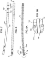
- FIGs. 1 and 2A respectively illustrate a side elevation and a cross-sectional view taken along line 2-2 in FIG. 1 of an intramedullary nail in accordance with some embodiments of the invention.
- the nail generally denoted at 30 is comprised of an elongated body 32 formed of a fiber reinforced polymer matrix as described above.
- body 30 includes one or more generally round screw holes (one being shown by way of example at 38), extending through body 32, a longitudinally elongated slot 40, also extending through body 32, and an crown portion generally denoted at 42, As shown in FIGs. 4 and 5 , proximal end 34 includes a threaded axial bore 44 extending into an connector portion 42, configured to engage an insertion tool as described below. Optionally, bore 44 extends axially a sufficient distance to communicate with the proximal end of slot 40 to facilitate axial compression of the nail to the bone prior to insertion of all the interlocking screws, and for connection of an implant removal tool, also as described below.
- body 32 At a distal end 36, body 32 includes one or more generally round screw holes (one of which is indicated at 46) extending sidewardly through body 32, and optionally, one or more generally round screw holes 48 extending for example at a 90 degree angle to screw hole 46.
- screw holes may be threaded, as indicated by hole 38, or unthreaded, as indicated by holes 46 and 48.
- Implants as described above formed of fiber reinforced polymer may be fabricated in any of several conventional ways, generally using heat and pressure such as compression molding, or injection molding. These are well known to persons of ordinary skill in the art, so further description is omitted in the interest of brevity.
- the implant may be fabricated by the known technique of holding a bundle of thermoplastic fibers oriented in a desired direction, and rapidly heating and cooling the fiber bundle under pressure in a mold so the outer the fibers melt together to create the matrix, while the core fibers do not have time to melt, and thus keep their very high strength,
- radiopaque markings are provided to assist the surgeon in locating screw holes 46 and 48, etc. and slot 40 for accurate insertion of bone fixation screws, not shown, but as described below.
- the markings may take various forms, as illustrated in FIGs. 1 and 2 , FIGs. 3A through 3C , and also FIGs. 9A and 9B .
- screw hole 46 is marked by four short metal rods or pins 50, two at each end of hole 46, best illustrated in FIGs. 2A and 3A .
- Rods 50 extend parallel to screw hole 46 and are equally spaced diametrically from the center of the hole, As best seen in FIG. 3A , rods 50a and 50c are located at one end of screw hole 46, and rods 50b and 50d are located at the opposite end. Rods 50a and 50b are aligned on one side of screw hole 46, and rods 50c and 50d are aligned on the opposite side.
- rods 50a and 50b and 50c and 50d respectively appear as single dots equally spaced diametrically from the center of the hole (see FIG. 1 ). By inserting the screw at the center thus indicated, and with the rods appearing as single dots, proper positioning of the screw is achieved.
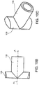
- FIG. 3A Another form of radiopaque marking is illustrated in FIG. 3A .
- the markings comprise two thin metal rings 52a and 52b located inside a screw hole 54. Rings 52 may be formed by plating the surface of hole 54, or may be inserted into the hold and radially expanded or may be inserted into the body of the implant as part of the molding process, As will be appreciated by those skilled in the art, when screw hole 54 is visualized fluoroscopically from the proper axial orientation, the rings 52a and 52b appear as a single circular ring.
- FIG. 3B illustrates a variation of the marking arrangement of FIG. 3A , in which a single metal tube 58 is provided extending substantially the entire length of the inside of a screw hole 56.
- marking is needed mainly for screw holes at the distal part of the nail.
- an external aiming device may be used that is attached to the proximal end of the nail during insertion, according to conventional practice
- body 32 may include one or more longitudinally extending wires, such as axial wire 59 (see FIG. 2 ).
- the wire is optionally located in a plane which subject to minimum change of length due to bending.
- a marking may optionally take the form of a thin metal tube on the inside of an internal lumen (see description below).
- a marking may optionally take the form of a thin metal tube on the inside of an internal lumen (see description below).
- Another option is to include a quantity of radiopaque filler, for example, barium, in the polymer matrix.
- Suitable metals for use as markings include, tantalum, gold, or other biocompatible materials having high atomic numbers.
- the metal is tantalum.
- wires such as 59 may have a diameter in the range of 0.05-0.4 mm, for example, 0.2 mm.
- Rods 50 may have a diameter in the range of 0.2 - 1 mm, for example, 0.7 mm.
- the proximal end of nail 30 comprises a connector including a threaded bore 44 for attachment of an implant insertion tool.
- a connector including a threaded bore 44 for attachment of an implant insertion tool.
- an end cap 60 configured to be threadedly received within threaded bore 44 upon completion of the nail implant procedure.
- end cap 60 The purpose of end cap 60 is to provide a closure for bore 44 which prevents regrowth of bone or other tissue inside the bore which would hinder insertion of an implant removal tool should removal of the implant later be necessary.
- End cap 60 includes slots 62 at its end to facilitate its own insertion and removal, but other configurations are possible, as will be recognized by persons skilled in the art.
- End cap 60 may optionally be formed of the same matrix material (for example PEEK) as body 32, without fibers, and may be fabricated in any conventional or desired manner. End cap material can include radiopaque marking, for example, spaced rods or pins 64.
- an implant such as a bone nail or plate is attached to the underlying bone by the fixation screws (not shown) which are threaded into the bone through holes in the bone implant.
- fixation screws not shown
- this is accomplished by making at least some of the screw holes slightly smaller than the outside diameter of the screw, or conversely, by making the outside diameters of the screws slightly larger than the screw holes.
- the screw holes may be threaded or unthreaded. When the screw holes are unthreaded, during insertion, the screw pushes the implant material aside, or cuts its own thread, and locks into the surrounding material.
- the thread pitch may be different on the holes and the screws so the two lock together due to the dimensional or pitch disparity.
- At least some of the screw holes such as 38 at the proximal end of implant 30 may include a ridge or rib similar to rib 154 shown in FIG. 3C that reduces the diameter of the hole in a localized area. When the screw is inserted, it deforms the material of the rib, or cuts a thread allowing it to lock into the implant.
- FIG. 3C illustrates an additional feature according to some embodiments of the invention.
- a bone nail is formed with a longitudinal slot 152, for example, at its proximal end 34.
- the surgeon can apply compression to the fracture site by attaching a screw to the bone through slot 152 and pulling the nail against the screw in the slot, optionally using the implant insertion tool.
- One or more other screws at the proximal end may then be added, for example, through hole 38, to anchor the nail.
- slot 152 may include a ridge or rib 154 to prevent withdrawal of the screw from the slot, as in the case of the round screw hole described above.
- a connector 70 shown in FIG. 4 includes a grouping of radial slots 72 (for example, three as illustrated), which are configured to engage a complementary end of a conventional implant insertion tool (not shown) in the required orientation, according to conventional implant insertion practice.
- radial slots 72 for example, three as illustrated
- more than one slot 72 is employed; as composite materials generally provide limited shear strength relative to metal, and multiple slots help assure sharing of the shear load imposed by the torque applied by the insertion handle.
- more than three slots 72 may be employed, provided they are arranged at the proper orientation relative to the insertion handle.
- connector 76 may have a single position at which it can connect to the insertion tool.
- this may be a generally hexagonal external configuration indicated at 78 capable of bearing torsion.
- connectors 70 and 76 are formed of the same reinforced polymer material as the rest of the implant body.
- the connectors may be formed of a metal end attachment (for example, titanium or the like) or ceramics molded into the proximal end of the implant body, provided it does not interfere unacceptably with CT or MRI visualization
- bone implants as described in connection with FIGs. 1-5 are formed of fiber layers designed to resist mainly bending forces, and mainly torsional forces.
- the term "mainly” is considered to mean that the forces encountered are at least about 75 percent bending forces or at least about 75 percent torsional forces.
- FIGs. 6A, 6B, and 6C show some details of a bone nail 89 according to such embodiments.
- core 90 and an outer layer 92 are formed of long substantially linearly extending fibers parallel to a longitudinal axis 94 within a polymer matrix.
- the nail is cannulated for illustrative purposes.
- an internal lumen 114 is covered with a metal layer 130, for example, a metal tube, optionally inserted during compression molding of the nail.
- the nail is non-cannulated.
- the core may be solid, but may be otherwise the same as core 90 illustrated.
- core 90 are multiple layers 100 of filaments in a polymer matrix helically wound in opposite directions, example, at ⁇ 45 degrees.
- Layers 100 are optionally wound or braided after manufacturing the longitudinal core 90. Optionally this may be formed by winding impregnated strips of composite material. One or more layers oriented in opposite direction are employed to resist the torque applied on the nail in the two directions of rotation.
- layer 100 is comprised of helically oriented filaments formed by winding multiple layers of impregnated strips of composite material in opposite directions, for example, at approximately +45 and -45 degrees.
- the windings 100 may be oriented at angles in the range of ⁇ 35 to 55 degrees.
- fibers may braided to combine two neighbor layers.
- the outer surface may be coated, at least partly, for example by plating, with a layer 110 of titanium, tantalum or similar metal
- metal outer surface 110 may be manufactured by compression molding the composite into a metal shell.
- the distal end 106 may be of the same construction as the proximal end. Illustratively, however, it is shown without a metal layer, and with only two helical layers 112.
- the inner, linear fiber layer embedded within the polymer matrix may have a diameter of up to 7.6 mm. If the nail is cannulated, internal lumen diameter may be 2.7mm, metal cover (if any) will be between diameters 2.7 to 2.9 mm.
- the second layer of helical fibers may have a thickness of 0.3 mm between diameter 7.6 mm and diameter 8.2 mm.
- the third (outer) layer of linearly extending fibers embedded in a polymer matrix may have a thickness of 0.15 mm between inner and outer diameters 8.2 mm and 8.5 mm.
- an inner lumen may have a 2.7 mm diameter
- metal cover if included
- linear fiber layer may have a diameters from 2.9 up to 7 mm.
- a first helical in -45 deg, orientation may be from 7 to 7.4 mm in diameter.
- a second layer of helical fibers in +45 deg may be from 7.4 mm to 7.8 mm in diameter.
- helical layer in +45 deg may be from 8.2 to 8.6 mm in diameter
- helical circular layer may be between 8.6 and 10.8 mm in diameter
- An outer layer of longitudinal fibers may be between 10.8 mm and 11.6mm. in diameter.
- a nail 107 may be cannulated.
- One optional use for a cannulated nail is repair of long bones such as the femur, tibia and humerus.
- nail 107 includes an elongated body 109 having a proximal end 110, a distal end 113, and a substantially central, axially extending lumen 114
- Distal end 113 includes a longitudinal slot 116 and a round hole 118 extending in the same direction through the nail, and round holes 120a and 120b extending at a 90 degree angle to slot 116 and hole 118.
- Proximal end 110 includes round screw holes 122 and 124, and a slot 126.
- Each of the screw holes and slots at distal end 113 and proximal end 110 of nail 107 may include radiopaque location markings. As seen in FIG. 9B , these may take the form of rods or pins 128 as described in connection with FIGs. 2A and 3C , or rings as described in connection with FIGs. 3A and 3B . Additionally, or alternatively, a thin metal tube 130 may be bonded in any suitable manner on the inner surface of lumen 114 (the distal end of which is best seen in FIG. 9B ).
- tube 130 As in the case of the embodiments employing wire 59 shown in FIG. 2 , or employing the radiopaque filler in the matrix, the continuity of tube 130 is interrupted by the screw holes and the slots, so that the longitudinal positions of these passages is indicated under fluoroscopy by the resulting discontinuities. As will be appreciated, tube 130 also serves to mark the location and extent of implant 107 itself.
- Cannulated implant 107 is otherwise the same as that previously described in connection with FIGs. 1, 2 , and may include a connector at its proximal end 110 like that described in connection with FIGs. 4 and 5 , and an end cap as described in connection with FIG. 2B . Also, it may be formed with the same layer configuration as in FIG. 6A . Accordingly, further description is omitted in the interest of brevity.
- implants according to some embodiments of the invention may include additional elements to improve performance, mainly strength.
- an insert can be made of metal or ceramics, or isotropic composite parts. One such embodiment is illustrated by way of example, in FIGs. 10A-10C .
- FIG. 10A there is shown an intramedullary nail 132 including a metal nut 134 to impart added strength to the connection between the implant, and the insertion handle. This may be embedded optionally into the implant during molding. Optionally, the nut 134 may by inserted into the proximal slot, and pushed into the proximal side of the nail.
- FIGs. 10B and 10C there are illustrated one option of the nut insert 134. As shown, nut 134 is generally T-shaped with a body 135 and opposed arms 136. When not molded in, nut 134 is oriented as shown in FIGs. 10B and 10C , and placed in slot 137 near its distal end 138. It is then moved in the proximal direction so that body is within the axial bore at the proximal end 139 of the implant.
- the surface of the implant may be provided with a metal coating or plating 141.
- the metal insert and the coating may be formed of titanium, titanium alloy or tantalum, or any other suitable and desired metal or metal alloy.
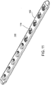
- FIG. 11 illustrates the construction of a bone plate 160 according to example not falling within the scope of the invention.
- Plate 160 is comprised of a longitudinal fibers coated with one, two, three, four layers of ⁇ 45° longitudinal wires, longitudinal fibers coated by one, two, three, four layers of woven or braided ⁇ 45° layers.
- plate 160 is comprised of a woven or braided body 162 formed of substantially linearly extending comingled long carbon and polymer filaments in a thermoplastic polymer matrix as previously described.
- Passages 170 are provided to receive bone fixation screws (not shown).
- passages 170 are formed in the molding process when plate 160 is fabricated. Alternatively, passages 170 are formed by machining after the plate has been fabricated.
- Passages 170 may be threaded or non-threaded or a combination of the two. Optionally only a portion of some or all the passages are threaded with the other part is non-threaded, and designed to engage with the screw head.
- bone plate 160 is preformed based on average anatomical data, and then bent to a final shape before implantation based on specific anatomical data concerning the actual implant site for a particular patient.
- the final shaping is done by heating the pre-formed implant in a molding press with suitably shaped inserts. Force is applied to bend the plate to the required shape, and then the mold is cooled in a manner which allows the implant to retain its bent shape without substantial change in its other properties.
- a bone plate formed of carbon fibers, in a PEEK matrix is heated to 380-400 Deg C, held at temperature for 5-30 minutes as needed to effect proper bending, then cooled at a rate of 5-30 Deg C per minute to 150 Deg C, and then cooled rapidly to room temperature.
- specific anatomical data for shaping plate 160 is obtained by direct measurement of the patient's implant site during a surgical procedure, or even visually.
- the specific anatomical data is obtained radiologically or by an MRI or by CT of the patient's implant site.
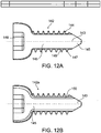
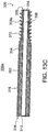
- FIG. 12A-12D illustrate a bone fixation screw suitable for use with the various implant embodiments described above, or as standalone for fixation of fractures without an implant.
- the illustrated screws may be formed of the same fiber reinforced or self reinforcing polymer materials as described above.
- the screws are comprised of a core 145 having long fibers extending in longitudinal direction, parallel to the screw axis 143 embedded in a polymer matrix.
- the thread 144 is made from composite material having long fibers, wound with the threads.
- some fibers may cross from the core and interweave into the thread as shown at 147, to increase the strength of the thread base 149.
- the thread 144 can be made of composite material with chopped fibers, optionally molded over the screw core.
- the screw connector 148 for engagement with the closing and opening tool may be of any conventional shape, for example, an internally or externally threaded hexagon, Phillips head, slotted, axial crown, and the like.
- the head of the screw may be a metal insert.
- FIG. 12B illustrates a bone fixation screw 142a, having a helical composite material layer 150, preferably with long fibers directed in +/- 45 deg relative to the axis 143. That layer may be included to add resistance to the torque applied on the screw during insertion or removal.
- layer 150 will comprise a winding only with one helical direction.
- the two fiber directions +/-45 deg are braided.
- FIG. 12C illustrates a screw 142b providing added shear strength, by having metal shell 152 outside composite core 145.
- Shell 152 may be solid, and comprise the entire thread with no composite component.
- Such a structure provides the strength of the metal to resist shearing of the thread, and the strength of the composite core to resist bending.
- the distal end of the screw will be part of the shell 154, and optionally, may be self tapping.
- FIG. 12D illustrates a screw 142c having the threads 144 coated with a thin layer 156 of titanium, or other metal such as titanium alloy Ti6A14V , or any other biocompatible metal or metal alloy.
- the metal coating should be thick enough to provide the needed additional strength, but thin enough that it does not cause artifacts in CT images or MRIs. Coating thicknesses in the range of about 0.02 to 0.2 mm provide satisfactory results. As a specific example, the coating may have a thickness of a 0.1 mm.
- the coating layer 156 may be formed in various ways including by electrochemical coating, physical vapor deposition, plasma spraying, molding the composite material into a metal shell etc. Whatever technique is employed, the coating should be made a smooth as possible, as a smooth surface is found to prevent attachment of re-grown tissue or bone to the threads, which would hinder removal of the screw if the implant must later be removed.
- bone screw can be made in any combination of the structural components described above.
- bone screw in any combination can be canullated, with an internal lumen sized for use with guide wire.
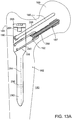
- FIG. 13A illustrates the construction of a proximal femur (PF) nail 180 formed of a reinforced polymer matrix, optionally including an embedded reinforcing insert as described above in connection with other embodiments of the invention.
- PF nails are used for repairing fractures involving the femur.
- PF nail 180 includes an elongated stem 182 having a proximal end 184 with at least one passage 186 oriented at an angle to a longitudinal axis 284 of the nail.
- passage 186 receives a proximal end bone fixation screw 286 which anchors the nail in the neck 188 and head 189 of the femur.
- PF nail 180 includes a threaded passage 190 to receive an anti-rotation pin 288.
- Passage 190 extends parallel to proximal end fixation screw passage 186.
- passage 186 is also threaded and receives a holder 192 within which leg screw 187 is slidingly received.
- a PF nail typically includes additional passages, such as passage 290 at a distal end 292.
- passage 290 receives a bone fixation screw for anchoring PF nail 180 to a lower portion of the femur.
- other passages may extend at an angle, for example, 90 degrees, to passage 290.
- PF nail 180 may include radiopaque markings for some or all of the passages.
- PF nail 180 includes an insertion tool connector 294 as described above, and an end cap 296 configured to be received in connector 294 after PF nail 180 has been implanted to prevent bone internal bone or tissue regrowth.
- leg screws are shown in FIGs. 13B and 13C .
- leg screws according to some embodiments of the invention are formed of a core of the same composite material and the nail.
- the screw is formed of metal, for example, a titanium alloy such as Ti-6A1-4V.
- a leg screw 300 includes a reinforced polymer core 302, and a surrounding metal shell 304.
- core 302 may include an internal lumen 306 intended to receive a guide wire (not shown) for assisting the surgeon during the implant procedure.
- Shell 304 includes threads 308 at least at its distal end 309 for interlocking with the surrounding bone.
- the threads are self tapping.
- Threads 308 may be formed only in shell 304 or may be internally relieved so that the polymer core 302 penetrates the threads, as best seen at 310 in FIG. 13C . In some instances, this may reduce the amount of metal in the shell for improved CT imaging and MRI visualization, and may help increase the strength of the connection between the screw core and the shell.
- the interface between the core and the shell may also include recesses and complementary projections of various shapes (not shown) to provide for stress sharing.
- the metal shell 316 is crimped around proximal and distal ends 318 and 320 of polymer core 322.
- FIGs. 14A-14C show an implant removal tool 200 according to an example not falling within the scope of the present invention.
- Removal tool 200 is configured to engage an installed implant 202 through the axial connector opening 204 at the proximal end 206 of the implant.
- axial opening 204 communicates with a transverse slot 208 as previously described.
- tool 200 includes first and second arms 210 and 212, having respective transverse tips 214 and 216 at their distal end, and a suitable handle (not shown) for easy manipulation at their proximal ends.
- Arms 210 and 212 are connected by a pivot intermediate the proximal and distal ends and thus provide a scissor mechanism operable to move tips 214 and 216 between retracted and extended positions. In the retracted position, the tips are close to each other so that the distal end of tool 200 is easily insertable into opening 204. In the extended position, tips are separated, and engage the opposite sides of slot 208.
- force can be applied to withdraw implant 202 from inside an opening in a bone.
- FIGs. 15A and15B show a bone drilling assembly 230 used to prepare an implant site to receive a bone implant according to some embodiments of the invention.
- the illustrated construction is designed to minimize interference with fluoroscopic visualization of the drilling site by the surgeon.
- Drilling assembly 230 includes a power unit 232 which drives a drill bit 234.
- An angled connector 236 is configured to be fitted between power unit 232 and drill bit 234.
- connector 236 includes a female coupling 238 for connection to drill bit 234, and a male connector 240 for connection to power unit 232.
- body 246 formed a polycarbonate or other suitable radiolucent material.
- a flexible cable 242 formed of for example multi-filaments of stainless steel or other suitable material is also mounted in body 246 and transfers torque from coupler 240 to coupler 238.
- connector 236 is angled at 250 so that couplers 238 and 240 are oriented, for example, at 90 degrees to each other. This allows power unit 232 to remain outside the fluoroscopy imaging range, and therefore does not interfere with visualization by the surgeon of the drilling site.
- Couplers 238 and 240 are of conventional design, or of any other suitable and desired type. According to some embodiments, couplers 238 and 240 include outer sleeves 252 and 254 formed of Teflon or the like, which serve as bearings to minimize friction during rotation. Cable 242 is sized to rotate freely relative to the body 246
- rigid elongated rods connected together by suitable right-angle gear arrangement may be employed. Preferably these parts are also formed of radiolucent material.
- Drill bit 234 may be made of a reinforced polymer matrix, optionally, including longitudinally extending reinforcing fibers as described above, coated with hard metal such as titanium, or diamond.
- Power unit 230 may be a standard operating room drill.
- Optionally angled connector 234 may include a self-contained, electric motor, gear and battery, in that device, a separate power unit 232 is not needed.
- the connector 236 constructed is provided in sterile packaging, and is intended for disposal after a single use.
- the nail at the proximal end is connected to the insertion handle with a bayonet connection.
- the proximal end nail includes longitudinal grooves 162 in order to insert the bayonet teeth 165 on the tube or rod 164 which connects the nail to the handle.
- Tube 164 rotates inside the nail in its radial groove 163.
- a nut 166 fastens over the tube 164 to tighten the nail to the handle.
- the nail proximal end does not include longitudinal grooves for insertion of the bayonet teeth. Instead, tube 134 includes expandable bayonet teeth.
- FIG. 17A and FIG. 17B illustrate a way to reduce cost during production of composite intramedullar nails.
- the nails are supplied in many lengths and diameters for humerus, tibia and femur bones, and are usually curved to follow the anatomic shape of the bones. However, it is less costly to manufacture straight nail, with all or most of the layers, and add a final manufacturing step of bending the nail.
- FIG. 17A illustrates a bending tool 170.
- tool 170 includes a cavity 171 to receive a straight nail.
- the tool has electric heaters 172 heating the tool with the nail inside to a suitable plastic deformation temperature.
- a suitable temperature is in the range of 380 to 410 deg C.
- pressure may be applied to the nail during heating, for example by pressing the nail axially via opening 173.
- the tool has two halves 174 and 175 defining a mold cavity, made of material capable to bend without damage, at the process temperature, such as Nitinol.
- FIG. 17B illustrates the tool after bending.
- the nail is cooled within the tool, and the resulting curve 176 is retained.
- PEEK and similar materials can be amorphous or crystalline to some degree, as determined by the desired heating and cooling treatment.
- Bending tool 170 has controller not shown, to establish the desired heating and cooling protocol.
- FIG. 18 shows an example of a drill guide and insertion tool 398 for use with an implant 400 according to some of the implant embodiments as described above.
- tool 398 is comprised of a body 402 having a drill guide holes 404 and a coupling portion 406 which engages the coupler portion 410 of implant 400.
- coupling portion 406 is an alignment element adapted to engage with a complementary element of the connector 410 to permit interconnection of the tool and the implant in the single orientation referred to in connection with FIGs. 4 and 5 .
Landscapes
- Health & Medical Sciences (AREA)
- Orthopedic Medicine & Surgery (AREA)
- Surgery (AREA)
- Life Sciences & Earth Sciences (AREA)
- Medical Informatics (AREA)
- Molecular Biology (AREA)
- Veterinary Medicine (AREA)
- Engineering & Computer Science (AREA)
- Biomedical Technology (AREA)
- Heart & Thoracic Surgery (AREA)
- Public Health (AREA)
- Nuclear Medicine, Radiotherapy & Molecular Imaging (AREA)
- Animal Behavior & Ethology (AREA)
- General Health & Medical Sciences (AREA)
- Neurology (AREA)
- Oral & Maxillofacial Surgery (AREA)
- Dentistry (AREA)
- Pathology (AREA)
- Surgical Instruments (AREA)
- Prostheses (AREA)
Priority Applications (1)
| Application Number | Priority Date | Filing Date | Title |
|---|---|---|---|
| EP17179078.5A EP3251618B8 (en) | 2009-01-16 | 2010-01-18 | Composite material bone implant |
Applications Claiming Priority (3)
| Application Number | Priority Date | Filing Date | Title |
|---|---|---|---|
| US20516009P | 2009-01-16 | 2009-01-16 | |
| US21399109P | 2009-08-06 | 2009-08-06 | |
| EP10702750.0A EP2389124B1 (en) | 2009-01-16 | 2010-01-18 | Composite material bone implant |
Related Parent Applications (2)
| Application Number | Title | Priority Date | Filing Date |
|---|---|---|---|
| EP10702750.0A Division EP2389124B1 (en) | 2009-01-16 | 2010-01-18 | Composite material bone implant |
| EP10702750.0A Division-Into EP2389124B1 (en) | 2009-01-16 | 2010-01-18 | Composite material bone implant |
Related Child Applications (2)
| Application Number | Title | Priority Date | Filing Date |
|---|---|---|---|
| EP17179078.5A Division EP3251618B8 (en) | 2009-01-16 | 2010-01-18 | Composite material bone implant |
| EP17179078.5A Division-Into EP3251618B8 (en) | 2009-01-16 | 2010-01-18 | Composite material bone implant |
Publications (2)
| Publication Number | Publication Date |
|---|---|
| EP3042621A1 EP3042621A1 (en) | 2016-07-13 |
| EP3042621B1 true EP3042621B1 (en) | 2017-08-09 |
Family
ID=42109958
Family Applications (3)
| Application Number | Title | Priority Date | Filing Date |
|---|---|---|---|
| EP15194868.4A Active EP3042621B1 (en) | 2009-01-16 | 2010-01-18 | Composite material bone implant |
| EP17179078.5A Active EP3251618B8 (en) | 2009-01-16 | 2010-01-18 | Composite material bone implant |
| EP10702750.0A Active EP2389124B1 (en) | 2009-01-16 | 2010-01-18 | Composite material bone implant |
Family Applications After (2)
| Application Number | Title | Priority Date | Filing Date |
|---|---|---|---|
| EP17179078.5A Active EP3251618B8 (en) | 2009-01-16 | 2010-01-18 | Composite material bone implant |
| EP10702750.0A Active EP2389124B1 (en) | 2009-01-16 | 2010-01-18 | Composite material bone implant |
Country Status (8)
Cited By (2)
| Publication number | Priority date | Publication date | Assignee | Title |
|---|---|---|---|---|
| US11457934B2 (en) | 2018-07-24 | 2022-10-04 | DePuy Synthes Products, Inc. | Intramedullary nail with wire or magnet for targeting of a bone-anchor locking hole |
| US11957391B2 (en) | 2021-11-01 | 2024-04-16 | Warsaw Orthopedic, Inc. | Bone screw having an overmold of a shank |
Families Citing this family (91)
| Publication number | Priority date | Publication date | Assignee | Title |
|---|---|---|---|---|
| US20030055316A1 (en) * | 2001-09-19 | 2003-03-20 | Brannon James Kevin | Endoscopic bone debridement |
| EP2094197B8 (en) | 2006-12-07 | 2016-03-09 | IHip Surgical, LLC | Apparatus for total hip replacement |
| US8579985B2 (en) * | 2006-12-07 | 2013-11-12 | Ihip Surgical, Llc | Method and apparatus for hip replacement |
| US8974540B2 (en) | 2006-12-07 | 2015-03-10 | Ihip Surgical, Llc | Method and apparatus for attachment in a modular hip replacement or fracture fixation device |
| US9320551B2 (en) * | 2007-01-26 | 2016-04-26 | Biomet Manufacturing, Llc | Lockable intramedullary fixation device |
| US9308031B2 (en) | 2007-01-26 | 2016-04-12 | Biomet Manufacturing, Llc | Lockable intramedullary fixation device |
| US9668775B2 (en) * | 2008-06-03 | 2017-06-06 | Jeffrey Scott Smith | Pedicle screw |
| US8986318B2 (en) | 2008-06-03 | 2015-03-24 | Jeffrey Scott Smith | Pedicle depth measuring apparatus |
| ES2645888T3 (es) | 2009-01-16 | 2017-12-11 | Carbofix Orthopedics Ltd. | Implante óseo de material de composite |
| US8926611B2 (en) * | 2009-09-14 | 2015-01-06 | Zimmer Gmbh | Angular lag implant for intramedullary nails |
| AU2010313415B2 (en) * | 2009-10-29 | 2015-09-03 | Prosidyan, Inc. | Dynamic bioactive bone graft material having an engineered porosity |
| WO2011111048A1 (en) * | 2010-03-10 | 2011-09-15 | Reuven Gepstein | Spinal implantable devices made of carbon composite materials and use thereof |
| US10154867B2 (en) | 2010-06-07 | 2018-12-18 | Carbofix In Orthopedics Llc | Multi-layer composite material bone screw |
| US9370388B2 (en) | 2010-06-07 | 2016-06-21 | Carbofix Orthopedics Ltd. | Composite material bone implant |
| AU2011293053B2 (en) * | 2010-08-25 | 2015-05-07 | Halifax Biomedical Inc. | A method of detecting movement between an implant and a bone |
| FR2967890B1 (fr) * | 2010-11-25 | 2013-12-20 | Mario Goldzak | Clou d'osteosynthese |
| CA2826703C (en) * | 2011-02-14 | 2019-06-25 | DePuy Synthes Products, LLC | Intramedullary nail having self-retaining compression slot |
| GB201105243D0 (en) | 2011-03-29 | 2011-05-11 | Depuy Ireland | An implant |
| US9861411B2 (en) | 2011-06-28 | 2018-01-09 | Spinologics Inc. | Bone screw, and bone fixation system and method |
| CN103648440B (zh) * | 2011-07-15 | 2017-08-08 | 史密夫和内修有限公司 | 减小植入物应力区 |
| US20130053847A1 (en) * | 2011-08-31 | 2013-02-28 | Mark Siravo | Implant Devices Constructed with Metallic and Polymeric Components |
| US9265541B2 (en) * | 2011-10-28 | 2016-02-23 | Stryker Trauma Gmbh | Intramedullary nail locking hole arrangement |
| US9526549B2 (en) | 2012-01-16 | 2016-12-27 | Carbofix Orthopedics Ltd. | Bone screw with insert |
| US20130184765A1 (en) | 2012-01-16 | 2013-07-18 | Carbofix Orthopedics Ltd. | Multi-axial bone plate fixation |
| WO2013151501A1 (en) * | 2012-04-04 | 2013-10-10 | Kok Sun Khong | Surgical implant device, method and apparatus for implanting thereof |
| US9345522B2 (en) * | 2012-05-22 | 2016-05-24 | Matthew Songer | Bone fixation screw and method |
| DE202012103384U1 (de) * | 2012-09-05 | 2012-09-24 | Signus Medizintechnik Gmbh | Beckenringimplantat |
| US9398928B2 (en) * | 2012-09-28 | 2016-07-26 | DePuy Synthes Products, Inc. | Adjustable height arthroplasty plate |
| EP2916755A4 (en) * | 2012-11-11 | 2015-12-02 | Carbofix Orthopedics Ltd | COATING FOR COMPOSITE IMPLANT |
| US10478236B2 (en) | 2013-01-04 | 2019-11-19 | Elemental Orthopedics Llc | Metal alloy mono and poly-filament wire reinforced carbon fiber plating system |
| US9044283B2 (en) | 2013-01-31 | 2015-06-02 | Stryker Trauma Gmbh | Bone nail with smooth trailing end |
| AU2013248170B2 (en) * | 2013-01-31 | 2015-05-28 | Stryker European Operations Holdings Llc | Bone nail with smooth trailing end |
| US20140243826A1 (en) * | 2013-02-28 | 2014-08-28 | Yechiel Gotfried | Method for connecting fractured bone |
| US9585695B2 (en) | 2013-03-15 | 2017-03-07 | Woven Orthopedic Technologies, Llc | Surgical screw hole liner devices and related methods |
| US20170042591A9 (en) * | 2013-12-12 | 2017-02-16 | Extremity Designs, Llc | Intramedullary anchor-screw fracture fixation |
| US9282975B2 (en) * | 2013-12-20 | 2016-03-15 | Spinal Generations, Llc | Drill bit and method for preparing a bone for a fixation screw |
| DE102014103972A1 (de) * | 2014-03-24 | 2015-09-24 | Christian Lutz | Verfahren zum Herstellen eines Implantats für die Osteosynthese |
| US9517094B1 (en) * | 2014-05-09 | 2016-12-13 | Savage Medical Design LLC | Intramedullary fixation apparatus for use in hip and femur fracture surgery |
| ES2752456T3 (es) * | 2014-07-03 | 2020-04-06 | Stryker European Holdings I Llc | Tapa de extremo cónica para clavo intramedular |
| US9907593B2 (en) | 2014-08-05 | 2018-03-06 | Woven Orthopedic Technologies, Llc | Woven retention devices, systems and methods |
| US8956394B1 (en) | 2014-08-05 | 2015-02-17 | Woven Orthopedic Technologies, Llc | Woven retention devices, systems and methods |
| CA2955392C (en) | 2014-09-07 | 2024-01-30 | Ossio Ltd. | Anisotropic biocomposite material, medical implants comprising same and methods of treatment thereof |
| US20160074071A1 (en) | 2014-09-16 | 2016-03-17 | Woven Orthopedic Technologies, Llc | Methods of using woven retention devices and systems |
| USD740427S1 (en) | 2014-10-17 | 2015-10-06 | Woven Orthopedic Technologies, Llc | Orthopedic woven retention device |
| US9918851B2 (en) * | 2014-10-22 | 2018-03-20 | Stryker European Holdings I, Llc | Spinal fusion implant |
| BR112017012508B1 (pt) | 2014-12-26 | 2022-04-12 | Ossio Ltd | Implante médico |
| US9855132B2 (en) * | 2015-01-30 | 2018-01-02 | Arthrex, Inc. | Ligament fixation device and method |
| US20220151664A1 (en) * | 2015-04-16 | 2022-05-19 | Texas Tech University System | Ankle (Tibio-Talar) Fusion Nail |
| TWI589263B (zh) * | 2015-06-04 | 2017-07-01 | 愛派司生技股份有限公司 | 一種用於股骨骨折之固定系統 |
| US10307588B2 (en) | 2015-06-30 | 2019-06-04 | Elemental Orthopedics Llc | Metal alloy mono and poly-filament wire reinforced carbon fiber plating system with electromagnetic bone stimulation |
| US10485595B2 (en) | 2015-07-13 | 2019-11-26 | IntraFuse, LLC | Flexible bone screw |
| US10154863B2 (en) | 2015-07-13 | 2018-12-18 | IntraFuse, LLC | Flexible bone screw |
| US10136929B2 (en) | 2015-07-13 | 2018-11-27 | IntraFuse, LLC | Flexible bone implant |
| US10499960B2 (en) | 2015-07-13 | 2019-12-10 | IntraFuse, LLC | Method of bone fixation |
| WO2017024277A1 (en) | 2015-08-05 | 2017-02-09 | Woven Orthopedic Technologies, Llc | Tapping devices, systems and methods for use in bone tissue |
| CN105221542B (zh) * | 2015-10-29 | 2018-01-09 | 创辉医疗器械江苏有限公司 | 防扩散焊锁定螺钉 |
| CN106667561A (zh) * | 2015-11-10 | 2017-05-17 | 胡军 | 一种用于股骨粗隆间骨折微创手术的动力髋装置 |
| US10448983B2 (en) * | 2015-12-07 | 2019-10-22 | Carbofix In Orthopedics Llc | Core and shell coupling of a composite material bone implant |
| US10617458B2 (en) | 2015-12-23 | 2020-04-14 | Carbofix In Orthopedics Llc | Multi-layer composite material bone screw |
| CN105861962A (zh) * | 2016-04-20 | 2016-08-17 | 苏州蔻美新材料有限公司 | 一种制造牙齿拆冠钳用复合材料及其制备方法 |
| EP3257474B1 (de) * | 2016-06-13 | 2019-09-18 | René Daniel Boesch | Endoprothese für einen röhrenknochen |
| EP3474913B1 (en) | 2016-06-27 | 2024-05-08 | Ossio Ltd | Fiber reinforced biocomposite medical implants with high mineral content |
| CN107789098A (zh) * | 2016-09-05 | 2018-03-13 | 财团法人金属工业研究发展中心 | 股骨支撑装置 |
| US10299847B2 (en) * | 2016-09-22 | 2019-05-28 | Globus Medical, Inc. | Systems and methods for intramedullary nail implantation |
| WO2018107114A1 (en) | 2016-12-09 | 2018-06-14 | Woven Orthopedic Technologies, LLC. | Retention devices, lattices and related systems and methods |
| EP3348288A3 (en) | 2017-01-13 | 2018-10-24 | M.M.A. Tech, Ltd. | Improved bone fixation devices |
| AT520250B1 (de) * | 2017-08-14 | 2019-11-15 | Surgebright Gmbh | Knochenschraube |
| CN107456259B (zh) * | 2017-08-14 | 2023-07-21 | 爱美客技术发展股份有限公司 | 一种固体植入物的推注装置 |
| CA3074809A1 (en) * | 2017-09-07 | 2019-03-14 | Ossio Ltd. | Fiber reinforced biocomposite threaded implants |
| US11253304B2 (en) | 2018-01-03 | 2022-02-22 | Glw, Inc. | Hybrid cannulated orthopedic screws |
| US10610270B2 (en) | 2018-01-15 | 2020-04-07 | Glw, Inc. | Hybrid intramedullary rods |
| CN108452371B (zh) * | 2018-03-08 | 2020-12-25 | 上海交通大学医学院附属仁济医院 | 一种口腔种植体的制备方法 |
| CN108938069B (zh) * | 2018-05-29 | 2020-07-03 | 瑞安市佰益医疗器械有限公司 | 一种股骨颈骨折的治疗装置 |
| CN113423352B (zh) * | 2019-02-07 | 2024-09-10 | 奥林巴斯泰尔茂生物材料株式会社 | 椎弓用螺杆及椎弓间隔物套件 |
| US11628000B2 (en) | 2019-03-18 | 2023-04-18 | Glw, Inc. | Hybrid bone plate |
| UY38363A (es) * | 2019-09-09 | 2021-02-26 | Emedical Sa | Prótesis elásticas de costillas |
| US11883243B2 (en) | 2019-10-31 | 2024-01-30 | Orthopediatrics Corp. | Assessment of tension between bone anchors |
| CN110916786A (zh) * | 2019-12-21 | 2020-03-27 | 王建华 | 骨固定系统 |
| AU2021278357A1 (en) | 2020-05-29 | 2023-01-19 | Stryker European Operations Limited | Funnel hole for intramedullary nail |
| KR102519621B1 (ko) * | 2020-06-22 | 2023-04-06 | 박명식 | 대퇴경간부 각도고정장치 |
| JP7446965B2 (ja) * | 2020-09-29 | 2024-03-11 | グローブライド株式会社 | 脊椎固定具用ロッド |
| EP4319666B1 (en) | 2021-04-09 | 2025-06-11 | GLW, Inc. | Hybrid bone plates and associated manufacturing processes |
| CN113116488A (zh) * | 2021-04-25 | 2021-07-16 | 西南医科大学附属医院 | 一种针对尺骨鹰嘴骨折的微创加压髓内固定系统 |
| JP2024523712A (ja) * | 2021-07-07 | 2024-06-28 | サージカル デザイン イノベーションズ ツー エルエルシー | 骨折固定デバイスならびに関連するシステムおよび方法 |
| IL294542A (en) | 2021-07-19 | 2023-02-01 | Ossio Ltd | Cannulated implant delivery device with adjustable insertion depth |
| IT202100028847A1 (it) * | 2021-11-12 | 2023-05-12 | Luciano Trinchese | Dispositivo per osteosintesi. |
| US12318124B2 (en) | 2021-11-29 | 2025-06-03 | Warsaw Orthopedic, Inc. | Continuous fiber bone screw and method of manufacture |
| CN114027960B (zh) * | 2022-01-07 | 2022-04-05 | 江苏百易得医疗科技有限公司 | 一种骨科植入物装置 |
| WO2023220264A1 (en) * | 2022-05-12 | 2023-11-16 | Glw, Inc. | Orthopedic screw with radiolucent and radiopaque thread portions |
| US20240261002A1 (en) * | 2023-02-02 | 2024-08-08 | Stryker European Operations Limited | Screw Hole Adapted for Different Screws |
| CN119214765A (zh) * | 2024-12-02 | 2024-12-31 | 天津正天医疗器械有限公司 | 一种角度可调的股骨髓内钉 |
Family Cites Families (176)
| Publication number | Priority date | Publication date | Assignee | Title |
|---|---|---|---|---|
| US3630253A (en) | 1969-10-22 | 1971-12-28 | Lamson & Sessions Co | Interference fastener |
| US4058581A (en) | 1972-07-24 | 1977-11-15 | Exxon Research & Engineering Co. | Method of making thermoplastic resin composite |
| US4220187A (en) | 1978-06-02 | 1980-09-02 | Holmes Horace D | Self-locking fastener |
| SU1111748A1 (ru) | 1983-04-08 | 1984-09-07 | Киевский медицинский институт | Устройство дл остеосинтеза трубчатых костей |
| FR2555902B1 (fr) | 1983-12-02 | 1990-09-14 | France Implant Est | Implants chirurgicaux en un materiau composite carbone/carbone, utiles notamment en orthopedie et en traumatologie |
| US4706659A (en) | 1984-12-05 | 1987-11-17 | Regents Of The University Of Michigan | Flexible connecting shaft for intramedullary reamer |
| US4667664A (en) | 1985-01-18 | 1987-05-26 | Richards Medical Company | Blind hole targeting device for orthopedic surgery |
| US4824314A (en) * | 1985-02-19 | 1989-04-25 | Northrop Corporation | Composite fastener system and manufacturing method thereof |
| US4750905A (en) | 1985-07-10 | 1988-06-14 | Harrington Arthritis Research Center | Beam construction and method |
| US4978360A (en) | 1986-03-03 | 1990-12-18 | Zimmer, Inc. | Method of manufacturing a composite implant prosthesis |
| US4718801A (en) * | 1986-07-24 | 1988-01-12 | Microdot Inc. | Composite core fastener |
| US5192330A (en) | 1987-01-20 | 1993-03-09 | Smith & Nephew Richards, Inc. | Orthopedic device of biocompatible polymer with oriented fiber reinforcement |
| US5064439A (en) | 1987-01-20 | 1991-11-12 | Richards Medical Company | Orthopedic device of biocompatible polymer with oriented fiber reinforcement |
| US4863330A (en) * | 1987-07-15 | 1989-09-05 | Northrop Corporation | Composite fastener and method of manufacture |
| DE3734108A1 (de) | 1987-10-06 | 1989-04-20 | Mecron Med Prod Gmbh | Marknagel fuer die behandlung von knochenbruechen |
| US4875474A (en) | 1988-01-29 | 1989-10-24 | Biomet, Inc. | Variable wall thickness interlocking intramedullary nail |
| JPH01197096A (ja) | 1988-02-01 | 1989-08-08 | Nippon Steel Corp | 消耗ノズル式エレクトロスラグ溶接法 |
| DE8808123U1 (de) | 1988-06-24 | 1988-09-22 | Herzberg, Wolfgang, Dr. med., 2000 Wedel | Laschenschraube für die Osteosynthese pertrochantärer Frakturen |
| DE8900080U1 (de) | 1988-09-21 | 1989-04-06 | Mecron Medizinische Produkte Gmbh, 1000 Berlin | Bausatz für die interne Fixation |
| US5522817A (en) | 1989-03-31 | 1996-06-04 | United States Surgical Corporation | Absorbable surgical fastener with bone penetrating elements |
| FR2646767A1 (fr) * | 1989-05-09 | 1990-11-16 | Medinov | Clou centro-medullaire |
| DE3923995A1 (de) | 1989-07-20 | 1991-01-31 | Lutz Biedermann | Stabilisierungselement fuer knochen |
| US5032125A (en) | 1990-02-06 | 1991-07-16 | Smith & Nephew Richards Inc. | Intramedullary hip screw |
| DE59107851D1 (de) | 1990-02-14 | 1996-07-04 | Man Ceramics Gmbh | Knochenimplantat |
| US5498265A (en) | 1991-03-05 | 1996-03-12 | Howmedica Inc. | Screw and driver |
| US5181930A (en) | 1991-04-10 | 1993-01-26 | Pfizer Hospital Products Group, Inc. | Composite orthopedic implant |
| US5320100A (en) * | 1991-09-16 | 1994-06-14 | Atrium Medical Corporation | Implantable prosthetic device having integral patency diagnostic indicia |
| JPH0592019A (ja) * | 1991-09-30 | 1993-04-16 | Terumo Corp | 人工関節 |
| DE69310345T2 (de) | 1992-01-21 | 1997-11-20 | Michael John Mcmahon | Chirurgische instrumente |
| JPH0592019U (ja) | 1992-05-22 | 1993-12-14 | マツダ株式会社 | 自動車のドア構造 |
| US5197966A (en) | 1992-05-22 | 1993-03-30 | Sommerkamp T Greg | Radiodorsal buttress blade plate implant for repairing distal radius fractures |
| US5348026A (en) | 1992-09-29 | 1994-09-20 | Smith & Nephew Richards Inc. | Osteoinductive bone screw |
| US5292215A (en) * | 1992-10-07 | 1994-03-08 | The United States Of America As Represented By The Secretary Of The Air Force | Metal bolt with a composite core for enhancement |
| DE4343117C2 (de) | 1993-12-17 | 1999-11-04 | Dietmar Wolter | Fixationssystem für Knochen |
| SE502627C2 (sv) | 1994-04-25 | 1995-11-27 | Sandvik Ab | Anordning för skydd mot överåtdragning av bultar, skruvar och dylikt |
| US5620445A (en) * | 1994-07-15 | 1997-04-15 | Brosnahan; Robert | Modular intramedullary nail |
| AU3635095A (en) | 1994-09-20 | 1996-04-09 | Smith & Nephew Richards Inc. | Composite threaded component and method of manufacture |
| ES2135635T3 (es) | 1994-10-14 | 1999-11-01 | Synthes Ag | Aparato de fijacion y/o de alineacion longitudinal para osteosintesis. |
| CZ295860B6 (cs) | 1994-12-19 | 2005-11-16 | Sepitec Foundation | Způsob výroby konstrukčních prvků z termoplastů vyztužených vlákny a konstrukční prvek vyrobený tímto způsobem |
| US6206881B1 (en) * | 1995-09-06 | 2001-03-27 | Synthes (Usa) | Bone plate |
| US5824079A (en) | 1996-08-23 | 1998-10-20 | Drexel University | Swelling type copolymeric composite material with self-fixation characteristics |
| US6030389A (en) | 1997-08-04 | 2000-02-29 | Spinal Concepts, Inc. | System and method for stabilizing the human spine with a bone plate |
| US6036696A (en) | 1997-12-19 | 2000-03-14 | Stryker Technologies Corporation | Guide-pin placement device and method of use |
| US6221075B1 (en) | 1998-03-06 | 2001-04-24 | Bionx Implants Oy | Bioabsorbable, deformable fixation plate |
| US5961524A (en) | 1998-03-11 | 1999-10-05 | Stryker Technologies Corporation | Screw and method of attachment to a substrate |
| DE19823737C2 (de) | 1998-05-27 | 2003-05-15 | Sepitec Foundation Vaduz | Verbundwerkstoff aus Polymer- oder Keramikmaterialien |
| JP3827890B2 (ja) | 1998-08-11 | 2006-09-27 | 株式会社八光 | 穿刺針ガイド器具 |
| DE19840298A1 (de) * | 1998-09-04 | 2000-03-16 | Ejot Verbindungstech Gmbh & Co | Selbstgewindeformende Schraube aus Leichtmetall und Verfahren zu ihrer Herstellung |
| EP1148830A1 (de) | 1999-02-04 | 2001-10-31 | Synthes Ag Chur | Knochenschraube |
| DE69915254T2 (de) | 1999-04-08 | 2005-03-10 | Orthofix International B.V. | Knochenschraube für orthopädische Chirurgie |
| US6342055B1 (en) | 1999-04-29 | 2002-01-29 | Theken Surgical Llc | Bone fixation system |
| AU3954200A (en) | 1999-05-03 | 2000-11-17 | Medartis Ag | Blockable bone plate |
| HK1043298B (zh) | 1999-08-27 | 2004-12-24 | Synthes Gmbh | 椎骨間植入物 |
| DE60026136T2 (de) | 1999-11-15 | 2006-11-23 | Arthrex Inc., Naples | Verjüngende bioabsorbierende Interferenzschraube zur ostealen Befestigung von Bändern |
| US7695502B2 (en) | 2000-02-01 | 2010-04-13 | Depuy Products, Inc. | Bone stabilization system including plate having fixed-angle holes together with unidirectional locking screws and surgeon-directed locking screws |
| US6605090B1 (en) | 2000-10-25 | 2003-08-12 | Sdgi Holdings, Inc. | Non-metallic implant devices and intra-operative methods for assembly and fixation |
| US6692498B1 (en) | 2000-11-27 | 2004-02-17 | Linvatec Corporation | Bioabsorbable, osteopromoting fixation plate |
| US6306140B1 (en) | 2001-01-17 | 2001-10-23 | Synthes (Usa) | Bone screw |
| EP1355593B1 (de) | 2001-01-30 | 2006-05-24 | Synthes AG Chur | Knochenimplantat, insbesondere zwischenwirbelimplantat |
| US8518090B2 (en) | 2010-10-05 | 2013-08-27 | Acumed Llc | Fastener with serrated thread for attachment to a bone plate at a selectable angle |
| US7717945B2 (en) | 2002-07-22 | 2010-05-18 | Acumed Llc | Orthopedic systems |
| US6648889B2 (en) | 2001-04-24 | 2003-11-18 | Dale G. Bramlet | Intramedullary hip nail with bifurcated lock |
| US6471707B1 (en) | 2001-05-11 | 2002-10-29 | Biomet | Bone screw having bioresorbable proximal shaft portion |
| ATE489904T1 (de) | 2001-06-27 | 2010-12-15 | Depuy Products Inc | Minimalinvasives orthopädisches gerät |
| FR2829378A1 (fr) | 2001-09-12 | 2003-03-14 | Hubert Hellak | Clou centro-medullaire verrouille |
| US6916321B2 (en) | 2001-09-28 | 2005-07-12 | Ethicon, Inc. | Self-tapping resorbable two-piece bone screw |
| US6921402B2 (en) | 2001-12-27 | 2005-07-26 | Ethicon, Inc. | Polymer-based orthopedic screw and driver system with increased insertion torque tolerance and associated method for making and using same |
| US7458991B2 (en) * | 2002-02-08 | 2008-12-02 | Howmedica Osteonics Corp. | Porous metallic scaffold for tissue ingrowth |
| US20030158555A1 (en) | 2002-02-15 | 2003-08-21 | Roy Sanders | Surgical screw and tool for its insertion |
| EP1485626B1 (en) | 2002-02-26 | 2007-06-06 | Degima Medizinprodukte GmbH | Threaded device with improved resistance against torsion-caused breakage |
| JP2004097794A (ja) | 2002-07-19 | 2004-04-02 | Pentax Corp | リン酸カルシウム−合成樹脂−金属複合体及びその製造方法 |
| FR2845588B1 (fr) | 2002-10-09 | 2006-12-15 | Biotech Internat | Dispositif d'osteosynthese autobloquant |
| US6955677B2 (en) | 2002-10-15 | 2005-10-18 | The University Of North Carolina At Chapel Hill | Multi-angular fastening apparatus and method for surgical bone screw/plate systems |
| CN1694653B (zh) | 2002-12-02 | 2010-07-14 | 斯恩蒂斯有限公司 | 用于骨固定术的植入物 |
| DE20300987U1 (de) | 2003-01-23 | 2003-04-10 | stryker Trauma GmbH, 24232 Schönkirchen | Implantat für die Osteosynthese |
| ES2348003T3 (es) | 2003-06-12 | 2010-11-26 | Synthes Gmbh | Clavo quirúrgico. |
| JP4825955B2 (ja) * | 2003-06-13 | 2011-11-30 | 独立行政法人産業技術総合研究所 | 生体インプラント材及びその作製方法 |
| AU2004249313B2 (en) | 2003-06-20 | 2009-01-15 | Acumed Llc | Bone plates with intraoperatively tapped apertures |
| US20050131413A1 (en) | 2003-06-20 | 2005-06-16 | O'driscoll Shawn W. | Bone plate with interference fit screw |
| CN1819799B (zh) * | 2003-08-26 | 2010-05-26 | 斯恩蒂斯有限公司 | 骨板 |
| KR101036055B1 (ko) | 2003-09-18 | 2011-05-19 | 신세스 게엠바하 | 대퇴부 골절의 치료 장치 |
| US8105367B2 (en) | 2003-09-29 | 2012-01-31 | Smith & Nephew, Inc. | Bone plate and bone plate assemblies including polyaxial fasteners |
| US6932818B2 (en) | 2003-10-30 | 2005-08-23 | Alfred F. Behrens | Intramedullary nail-based bone fracture treatment |
| US8574268B2 (en) | 2004-01-26 | 2013-11-05 | DePuy Synthes Product, LLC | Highly-versatile variable-angle bone plate system |
| US20050192578A1 (en) | 2004-02-26 | 2005-09-01 | Horst Steven P. | Bone plates with locking apertures |
| WO2005094707A2 (en) | 2004-03-26 | 2005-10-13 | Smith & Nephew, Inc. | Methods for treating fractures of the femur and femoral fracture devices |
| EP1598028B1 (en) | 2004-05-19 | 2007-12-12 | Straumann Holding AG | One-piece dental device and method to manufacture the same |
| US20060004431A1 (en) * | 2004-07-01 | 2006-01-05 | Fuller Thomas A | Prophylactic bactericidal implant |
| US20060015110A1 (en) | 2004-07-15 | 2006-01-19 | Pepper John R | Cutting device |
| DE102004035546A1 (de) | 2004-07-19 | 2006-02-16 | Wolter, Dietmar, Prof. Dr.Med. | Fixationssystem für Knochen und Füllkörper für ein Fixationssystem für Knochen |
| US20060041261A1 (en) | 2004-08-17 | 2006-02-23 | Osypka Thomas P | Apparatus and method for attaching connective tissue to bone |
| CN1586416A (zh) * | 2004-09-06 | 2005-03-02 | 武汉理工大学 | 适合口腔骨折固定的可吸收复合接骨板及制备方法 |
| US7481815B2 (en) * | 2004-09-23 | 2009-01-27 | Synthes (U.S.A.) | Coplanar X-ray guided aiming arm for locking of intramedullary nails |
| CN2746884Y (zh) * | 2004-12-02 | 2005-12-21 | 冀原 | 骨折内固定弹性动力交锁髓内钉 |
| US20060149264A1 (en) | 2004-12-20 | 2006-07-06 | Castaneda Javier E | Screw locking systems for bone plates |
| DE202005000508U1 (de) | 2005-01-13 | 2005-05-12 | Königsee Implantate und Instrumente zur Osteosynthese GmbH | Kleinfragment-Humeruskopfplatte |
| CA2596266C (en) | 2005-01-28 | 2015-03-31 | Depuy Products, Inc. | Nail plate system |
| US20060195085A1 (en) | 2005-02-01 | 2006-08-31 | Inion Ltd. | System and method for stabilizing spine |
| US7232442B2 (en) * | 2005-02-22 | 2007-06-19 | Advanced Orthopaedic Solutions | Humeral nail |
| ITVI20050049A1 (it) | 2005-02-22 | 2006-08-23 | Tecres Spa | Dispositivo monouso per il trattamento di infezioni di arti del corpo umano, particolarmente di arti con ossa lunghe |
| US7824433B2 (en) | 2005-05-03 | 2010-11-02 | Williams Lytton A | Bone anchored surgical mesh |
| FI119969B (fi) | 2005-05-06 | 2009-05-29 | Inion Ltd | Levy ja järjestelmä luuosien kiinnittämiseksi |
| US7909825B2 (en) | 2006-11-22 | 2011-03-22 | Sonoma Orthepedic Products, Inc. | Fracture fixation device, tools and methods |
| WO2006124764A1 (en) | 2005-05-18 | 2006-11-23 | Sonoma Orthopedic Products, Inc. | Minimally invasive actuable bone fixation devices, systems and methods of use |
| WO2009152272A1 (en) | 2008-06-10 | 2009-12-17 | Sonoma Orthopedic Products, Inc. | Fracture fixation device, tools and methods |
| US8961516B2 (en) | 2005-05-18 | 2015-02-24 | Sonoma Orthopedic Products, Inc. | Straight intramedullary fracture fixation devices and methods |
| CN2801080Y (zh) | 2005-05-23 | 2006-08-02 | 杨立群 | 旋入式髓内钉 |
| US20060282168A1 (en) * | 2005-06-13 | 2006-12-14 | Sherman Jason T | Orthopaedic prosthesis having a superparamagnetic material and associated method |
| WO2007009123A2 (en) | 2005-07-14 | 2007-01-18 | Stout Medical Group, L.P. | Implant systems and methods for use |
| JP2007021001A (ja) | 2005-07-20 | 2007-02-01 | Me System:Kk | 骨折治療用インプラント |
| US9192398B2 (en) | 2005-09-19 | 2015-11-24 | DePuy Synthes Products, Inc. | Orthopedic implant insertion handle and aiming guide |
| US7955364B2 (en) | 2005-09-21 | 2011-06-07 | Ebi, Llc | Variable angle bone fixation assembly |
| WO2007048038A2 (en) | 2005-10-21 | 2007-04-26 | Acumed Llc | Orthopedic rod with locking aperture |
| US20070123875A1 (en) * | 2005-10-31 | 2007-05-31 | Czartoski Timothy J | Intramedullary nail |
| US8551145B2 (en) | 2005-12-19 | 2013-10-08 | Mayo Foundation For Medical Education And Research | Anterior adherent thoracolumbar spine plate |
| US8100952B2 (en) | 2005-12-22 | 2012-01-24 | Anthem Orthopaedics Llc | Drug delivering bone plate and method and targeting device for use therewith |
| CN101500499A (zh) | 2006-01-13 | 2009-08-05 | 生物动力有限责任公司 | 具有可生物吸收部件的外科紧固件和相关植入设备 |
| US8491593B2 (en) | 2006-01-17 | 2013-07-23 | Stryker Trauma Gmbh | Targeting device for orthopedic implants |
| US8372074B2 (en) | 2006-02-03 | 2013-02-12 | Miles C. Milbank | Multi-articulated fracture fixation device with adjustable modulus of rigidity |
| US7785325B1 (en) | 2006-02-03 | 2010-08-31 | Milbank Miles C | Multi-articulated fracture fixation device with adjustable modulus of rigidity |
| US7850717B2 (en) | 2006-03-01 | 2010-12-14 | Warsaw Orthopedic, Inc. | Bone anchors having two or more portions exhibiting different performance characteristics and method of forming the same |
| US8900321B2 (en) * | 2006-03-20 | 2014-12-02 | Zimmer, Inc. | Implant anchoring device |
| FI119177B (fi) | 2006-05-05 | 2008-08-29 | Bioretec Oy | Bioabsorboituva, muotoutuva fiksaatiomateriaali ja -implantti |
| JP4703508B2 (ja) * | 2006-08-04 | 2011-06-15 | シンセス株式会社 | 髄内釘およびこれを備えたネイリングシステム |
| US8267978B2 (en) | 2006-09-14 | 2012-09-18 | Warsaw Orthopedic, Inc. | Hybrid bone fixation apparatus |
| GB2442706A (en) | 2006-10-09 | 2008-04-16 | Mohamed Khalid | An intramedullary rod for the fixation of bone fractures |
| JP2010512981A (ja) | 2006-12-19 | 2010-04-30 | スモール・ボーン・イノベーションズ・インコーポレーテッド | ロッキング固定システムおよびラグ工具 |
| DE202006019220U1 (de) | 2006-12-19 | 2007-05-24 | Zrinski Ag | Orthopädisches Schraubenverschlusssystem |
| WO2008092192A1 (en) * | 2007-01-29 | 2008-08-07 | The University Of Sydney | An intervertebral disk prosthesis |
| US7763023B2 (en) | 2007-02-09 | 2010-07-27 | Yechiel Gotfried | Intramedullary nail system and method for fixation of a fractured bone |
| US20080234762A1 (en) | 2007-03-06 | 2008-09-25 | Zimmer Technology, Inc. | Self-tapping screw with resorbable tip |
| US8764764B2 (en) | 2007-03-21 | 2014-07-01 | The University Of North Carolina At Chapel Hill | Surgical plate puller devices and methods for use with surgical bone screw/plate systems |
| AU2008228710A1 (en) | 2007-03-22 | 2008-09-25 | Novalign Orthopaedics, Inc. | Segmented intramedullary structure |
| ES2595308T3 (es) * | 2007-06-22 | 2016-12-29 | Epix Orthopaedics, Inc. | Varilla intramedular con sujetador pivotante |
| US8388666B2 (en) | 2007-09-27 | 2013-03-05 | Biomet C.V. | Locking screw system with relatively hard spiked polyaxial bushing |
| US7914244B2 (en) | 2007-10-03 | 2011-03-29 | Illinois Tool Works Inc. | Fastener with zoned, varying wave-form thread |
| WO2009058969A1 (en) | 2007-10-30 | 2009-05-07 | Synthes (U.S.A.) | Variable angle locked bone plate |
| US20090228048A1 (en) | 2008-03-10 | 2009-09-10 | Duncan Scott F M | Joint Fixation System For the Hand |
| US9072561B2 (en) | 2008-03-25 | 2015-07-07 | The Center For Orthopedic Research And Education, Inc. | Spinal facet fixation device |
| WO2009121144A1 (en) | 2008-04-03 | 2009-10-08 | Austofix Group Limited | Tool jig for bone implant assembly |
| EP2309937A2 (en) | 2008-05-23 | 2011-04-20 | Novalign Orthopaedics, Inc. | Modular segmented intramedullary system, apparatus and associated methods |
| WO2009152270A1 (en) | 2008-06-10 | 2009-12-17 | Sonoma Orthopedic Products, Inc. | Fracture fixation device, tools and methods |
| US8100911B2 (en) | 2008-06-30 | 2012-01-24 | Depuy Products, Inc. | Fracture fixation apparatus |
| US9072555B2 (en) | 2008-07-21 | 2015-07-07 | Arthrex, Inc. | Carbon fiber reinforced peek bone plate with titanium fixation screws |
| ES2647919T3 (es) | 2008-08-13 | 2017-12-27 | Smed-Ta/Td, Llc | Implantes de suministro de fármaco |
| US9358056B2 (en) | 2008-08-13 | 2016-06-07 | Smed-Ta/Td, Llc | Orthopaedic implant |
| CN102123674A (zh) | 2008-08-15 | 2011-07-13 | 活动脊柱技术有限公司 | 动态椎弓根螺钉 |
| US7896599B2 (en) * | 2008-08-21 | 2011-03-01 | Douglas Stephen | Hybrid composite-metal male fastener |
| US20110288598A1 (en) | 2008-09-08 | 2011-11-24 | Saint Louis University | Locking screw device |
| US20100094423A1 (en) | 2008-10-15 | 2010-04-15 | Warsaw Orthopedic, Inc. | Systems and methods for assessment of tension in an implant |
| EP2364115B1 (en) | 2008-10-15 | 2019-02-20 | Smith & Nephew, Inc. | Composite internal fixators |
| US8597334B2 (en) | 2008-10-17 | 2013-12-03 | Osteomed Llc | Angulated locking plate/screw interface |
| DE102008043370A1 (de) | 2008-10-31 | 2010-05-06 | Universität Rostock | Fixationsvorrichtung für Knochen |
| EP2198792A1 (de) | 2008-12-19 | 2010-06-23 | Sepitec Foundation | Implantatsystem zum Stabilisieren von Knochen |
| US8617225B2 (en) | 2008-12-24 | 2013-12-31 | DePuy Synthes Products, LLC | Spline drive for threaded post-type bone anchors |
| ES2645888T3 (es) | 2009-01-16 | 2017-12-11 | Carbofix Orthopedics Ltd. | Implante óseo de material de composite |
| ES2687256T3 (es) | 2009-01-27 | 2018-10-24 | Intra-Lock International Inc. | Implante autorroscante |
| WO2010132830A2 (en) | 2009-05-15 | 2010-11-18 | Smith & Nephew, Inc. | Polyaxial fastener systems and methods |
| US20120065638A1 (en) | 2009-05-21 | 2012-03-15 | Sonoma Orthopedic Products, Inc. | Snap and twist segmented intramedullary system, apparatus and associated methods |
| US9259255B2 (en) | 2009-07-15 | 2016-02-16 | Orthohelix Surgical Designs, Inc. | Variable axis locking mechanism for use in orthopedic implants |
| ES2522822T3 (es) | 2009-08-13 | 2014-11-18 | Cork Institute Of Technology | Clavos intramedulares para reducción de fractura de hueso largo |
| ES2710179T3 (es) | 2009-09-07 | 2019-04-23 | Nobel Biocare Services Ag | Conjunto de implantación |
| SM200900081B (it) | 2009-10-05 | 2010-11-12 | Hit Medica S P A | Sistema placche per osteosintesi con viti pluriassiali a stabilità angolare in materiale polimerico. |
| US8801712B2 (en) | 2010-03-08 | 2014-08-12 | Innovasis, Inc. | Radiolucent bone plate with radiopaque marker |
| WO2011111048A1 (en) | 2010-03-10 | 2011-09-15 | Reuven Gepstein | Spinal implantable devices made of carbon composite materials and use thereof |
| US9113970B2 (en) | 2010-03-10 | 2015-08-25 | Orthohelix Surgical Designs, Inc. | System for achieving selectable fixation in an orthopedic plate |
| US9370388B2 (en) | 2010-06-07 | 2016-06-21 | Carbofix Orthopedics Ltd. | Composite material bone implant |
| US10154867B2 (en) | 2010-06-07 | 2018-12-18 | Carbofix In Orthopedics Llc | Multi-layer composite material bone screw |
| CN103025257A (zh) | 2010-07-28 | 2013-04-03 | 斯恩蒂斯有限公司 | 使用具有径向切口的生物可降解螺钉的系统或骨头固定器 |
| WO2012107913A2 (en) | 2011-02-13 | 2012-08-16 | Carbofix Orthopedics Ltd. | Flexible transparent bone implant |
| US9907592B2 (en) | 2011-05-06 | 2018-03-06 | Syberspine Limited | Self guiding surgical bone fixation screw |
| US9526549B2 (en) | 2012-01-16 | 2016-12-27 | Carbofix Orthopedics Ltd. | Bone screw with insert |
| US20130218214A1 (en) | 2012-01-16 | 2013-08-22 | Carbofix Orthopedics Ltd. | Bone screw head design |
| US20130184765A1 (en) | 2012-01-16 | 2013-07-18 | Carbofix Orthopedics Ltd. | Multi-axial bone plate fixation |
| US20130261675A1 (en) | 2012-03-28 | 2013-10-03 | Daniel Duane Fritzinger | Loose thread form for variable angle locking systems |
| US10617458B2 (en) | 2015-12-23 | 2020-04-14 | Carbofix In Orthopedics Llc | Multi-layer composite material bone screw |
-
2010
- 2010-01-18 ES ES15194868.4T patent/ES2645888T3/es active Active
- 2010-01-18 EP EP15194868.4A patent/EP3042621B1/en active Active
- 2010-01-18 EP EP17179078.5A patent/EP3251618B8/en active Active
- 2010-01-18 EP EP10702750.0A patent/EP2389124B1/en active Active
- 2010-01-18 CN CN201410413164.7A patent/CN104188708B/zh active Active
- 2010-01-18 CN CN201410412613.6A patent/CN104188706B/zh active Active
- 2010-01-18 CA CA2749684A patent/CA2749684C/en active Active
- 2010-01-18 CN CN201410413073.3A patent/CN104188707A/zh active Pending
- 2010-01-18 JP JP2011545832A patent/JP2012515038A/ja active Pending
- 2010-01-18 WO PCT/IB2010/050225 patent/WO2010082183A2/en active Application Filing
- 2010-01-18 US US13/144,938 patent/US8709055B2/en active Active
- 2010-01-18 CN CN201080012276.1A patent/CN102355863B/zh active Active
-
2011
- 2011-07-14 IL IL214105A patent/IL214105A/en active IP Right Grant
-
2014
- 2014-04-07 US US14/246,161 patent/US9101417B2/en active Active
-
2015
- 2015-07-02 JP JP2015133386A patent/JP2015186641A/ja active Pending
- 2015-07-29 US US14/811,859 patent/US10028777B2/en active Active
Non-Patent Citations (1)
| Title |
|---|
| None * |
Cited By (3)
| Publication number | Priority date | Publication date | Assignee | Title |
|---|---|---|---|---|
| US11457934B2 (en) | 2018-07-24 | 2022-10-04 | DePuy Synthes Products, Inc. | Intramedullary nail with wire or magnet for targeting of a bone-anchor locking hole |
| US12167859B2 (en) | 2018-07-24 | 2024-12-17 | DePuy Synthes Products, Inc. | Intramedullary nail with wire or magnet for targeting of a bone-anchor locking hole |
| US11957391B2 (en) | 2021-11-01 | 2024-04-16 | Warsaw Orthopedic, Inc. | Bone screw having an overmold of a shank |
Also Published As
| Publication number | Publication date |
|---|---|
| US10028777B2 (en) | 2018-07-24 |
| IL214105A0 (en) | 2011-08-31 |
| CN104188707A (zh) | 2014-12-10 |
| EP3251618A1 (en) | 2017-12-06 |
| EP3042621A1 (en) | 2016-07-13 |
| CA2749684A1 (en) | 2010-07-22 |
| CN102355863B (zh) | 2014-09-17 |
| ES2645888T3 (es) | 2017-12-11 |
| CA2749684C (en) | 2016-04-26 |
| WO2010082183A2 (en) | 2010-07-22 |
| EP2389124B1 (en) | 2016-01-06 |
| CN104188706B (zh) | 2016-08-31 |
| WO2010082183A9 (en) | 2010-09-02 |
| EP3251618B1 (en) | 2019-10-09 |
| US8709055B2 (en) | 2014-04-29 |
| US20150327893A1 (en) | 2015-11-19 |
| EP3251618B8 (en) | 2019-11-13 |
| CN104188706A (zh) | 2014-12-10 |
| IL214105A (en) | 2015-04-30 |
| CN104188708B (zh) | 2017-07-14 |
| US20110282395A1 (en) | 2011-11-17 |
| JP2012515038A (ja) | 2012-07-05 |
| CN102355863A (zh) | 2012-02-15 |
| WO2010082183A3 (en) | 2011-01-06 |
| JP2015186641A (ja) | 2015-10-29 |
| US20140222001A1 (en) | 2014-08-07 |
| CN104188708A (zh) | 2014-12-10 |
| US9101417B2 (en) | 2015-08-11 |
| EP2389124A2 (en) | 2011-11-30 |
Similar Documents
| Publication | Publication Date | Title |
|---|---|---|
| EP3042621B1 (en) | Composite material bone implant | |
| US10849668B2 (en) | Composite material bone implant | |
| EP2364115B1 (en) | Composite internal fixators | |
| US20130325007A1 (en) | Segmented intramedullary implant | |
| EP2328484A2 (en) | Catheter nail targeting guide | |
| CN114027960B (zh) | 一种骨科植入物装置 |
Legal Events
| Date | Code | Title | Description |
|---|---|---|---|
| PUAI | Public reference made under article 153(3) epc to a published international application that has entered the european phase |
Free format text: ORIGINAL CODE: 0009012 |
|
| 17P | Request for examination filed |
Effective date: 20151117 |
|
| AC | Divisional application: reference to earlier application |
Ref document number: 2389124 Country of ref document: EP Kind code of ref document: P |
|
| AK | Designated contracting states |
Kind code of ref document: A1 Designated state(s): AT BE BG CH CY CZ DE DK EE ES FI FR GB GR HR HU IE IS IT LI LT LU LV MC MK MT NL NO PL PT RO SE SI SK SM TR |
|
| GRAP | Despatch of communication of intention to grant a patent |
Free format text: ORIGINAL CODE: EPIDOSNIGR1 |
|
| STAA | Information on the status of an ep patent application or granted ep patent |
Free format text: STATUS: GRANT OF PATENT IS INTENDED |
|
| RIC1 | Information provided on ipc code assigned before grant |
Ipc: A61B 17/78 20060101ALI20170131BHEP Ipc: A61B 17/16 20060101AFI20170131BHEP Ipc: A61B 17/86 20060101ALI20170131BHEP Ipc: A61B 17/80 20060101ALI20170131BHEP Ipc: A61B 17/88 20060101ALI20170131BHEP Ipc: A61B 17/72 20060101ALI20170131BHEP |
|
| INTG | Intention to grant announced |
Effective date: 20170301 |
|
| GRAS | Grant fee paid |
Free format text: ORIGINAL CODE: EPIDOSNIGR3 |
|
| GRAA | (expected) grant |
Free format text: ORIGINAL CODE: 0009210 |
|
| STAA | Information on the status of an ep patent application or granted ep patent |
Free format text: STATUS: THE PATENT HAS BEEN GRANTED |
|
| AC | Divisional application: reference to earlier application |
Ref document number: 2389124 Country of ref document: EP Kind code of ref document: P |
|
| AK | Designated contracting states |
Kind code of ref document: B1 Designated state(s): AT BE BG CH CY CZ DE DK EE ES FI FR GB GR HR HU IE IS IT LI LT LU LV MC MK MT NL NO PL PT RO SE SI SK SM TR |
|
| REG | Reference to a national code |
Ref country code: GB Ref legal event code: FG4D |
|
| REG | Reference to a national code |
Ref country code: CH Ref legal event code: EP Ref country code: AT Ref legal event code: REF Ref document number: 915942 Country of ref document: AT Kind code of ref document: T Effective date: 20170815 |
|
| REG | Reference to a national code |
Ref country code: IE Ref legal event code: FG4D |
|
| REG | Reference to a national code |
Ref country code: DE Ref legal event code: R096 Ref document number: 602010044380 Country of ref document: DE |
|
| REG | Reference to a national code |
Ref country code: ES Ref legal event code: FG2A Ref document number: 2645888 Country of ref document: ES Kind code of ref document: T3 Effective date: 20171211 |
|
| REG | Reference to a national code |
Ref country code: NL Ref legal event code: MP Effective date: 20170809 |
|
| REG | Reference to a national code |
Ref country code: LT Ref legal event code: MG4D |
|
| REG | Reference to a national code |
Ref country code: AT Ref legal event code: MK05 Ref document number: 915942 Country of ref document: AT Kind code of ref document: T Effective date: 20170809 |
|
| REG | Reference to a national code |
Ref country code: FR Ref legal event code: PLFP Year of fee payment: 9 |
|
| PG25 | Lapsed in a contracting state [announced via postgrant information from national office to epo] |
Ref country code: NL Free format text: LAPSE BECAUSE OF FAILURE TO SUBMIT A TRANSLATION OF THE DESCRIPTION OR TO PAY THE FEE WITHIN THE PRESCRIBED TIME-LIMIT Effective date: 20170809 Ref country code: SE Free format text: LAPSE BECAUSE OF FAILURE TO SUBMIT A TRANSLATION OF THE DESCRIPTION OR TO PAY THE FEE WITHIN THE PRESCRIBED TIME-LIMIT Effective date: 20170809 Ref country code: LT Free format text: LAPSE BECAUSE OF FAILURE TO SUBMIT A TRANSLATION OF THE DESCRIPTION OR TO PAY THE FEE WITHIN THE PRESCRIBED TIME-LIMIT Effective date: 20170809 Ref country code: HR Free format text: LAPSE BECAUSE OF FAILURE TO SUBMIT A TRANSLATION OF THE DESCRIPTION OR TO PAY THE FEE WITHIN THE PRESCRIBED TIME-LIMIT Effective date: 20170809 Ref country code: NO Free format text: LAPSE BECAUSE OF FAILURE TO SUBMIT A TRANSLATION OF THE DESCRIPTION OR TO PAY THE FEE WITHIN THE PRESCRIBED TIME-LIMIT Effective date: 20171109 Ref country code: FI Free format text: LAPSE BECAUSE OF FAILURE TO SUBMIT A TRANSLATION OF THE DESCRIPTION OR TO PAY THE FEE WITHIN THE PRESCRIBED TIME-LIMIT Effective date: 20170809 Ref country code: AT Free format text: LAPSE BECAUSE OF FAILURE TO SUBMIT A TRANSLATION OF THE DESCRIPTION OR TO PAY THE FEE WITHIN THE PRESCRIBED TIME-LIMIT Effective date: 20170809 |
|
| PG25 | Lapsed in a contracting state [announced via postgrant information from national office to epo] |
Ref country code: GR Free format text: LAPSE BECAUSE OF FAILURE TO SUBMIT A TRANSLATION OF THE DESCRIPTION OR TO PAY THE FEE WITHIN THE PRESCRIBED TIME-LIMIT Effective date: 20171110 Ref country code: LV Free format text: LAPSE BECAUSE OF FAILURE TO SUBMIT A TRANSLATION OF THE DESCRIPTION OR TO PAY THE FEE WITHIN THE PRESCRIBED TIME-LIMIT Effective date: 20170809 Ref country code: BG Free format text: LAPSE BECAUSE OF FAILURE TO SUBMIT A TRANSLATION OF THE DESCRIPTION OR TO PAY THE FEE WITHIN THE PRESCRIBED TIME-LIMIT Effective date: 20171109 Ref country code: IS Free format text: LAPSE BECAUSE OF FAILURE TO SUBMIT A TRANSLATION OF THE DESCRIPTION OR TO PAY THE FEE WITHIN THE PRESCRIBED TIME-LIMIT Effective date: 20171209 Ref country code: PL Free format text: LAPSE BECAUSE OF FAILURE TO SUBMIT A TRANSLATION OF THE DESCRIPTION OR TO PAY THE FEE WITHIN THE PRESCRIBED TIME-LIMIT Effective date: 20170809 |
|
| PG25 | Lapsed in a contracting state [announced via postgrant information from national office to epo] |
Ref country code: DK Free format text: LAPSE BECAUSE OF FAILURE TO SUBMIT A TRANSLATION OF THE DESCRIPTION OR TO PAY THE FEE WITHIN THE PRESCRIBED TIME-LIMIT Effective date: 20170809 Ref country code: RO Free format text: LAPSE BECAUSE OF FAILURE TO SUBMIT A TRANSLATION OF THE DESCRIPTION OR TO PAY THE FEE WITHIN THE PRESCRIBED TIME-LIMIT Effective date: 20170809 Ref country code: CZ Free format text: LAPSE BECAUSE OF FAILURE TO SUBMIT A TRANSLATION OF THE DESCRIPTION OR TO PAY THE FEE WITHIN THE PRESCRIBED TIME-LIMIT Effective date: 20170809 |
|
| REG | Reference to a national code |
Ref country code: DE Ref legal event code: R097 Ref document number: 602010044380 Country of ref document: DE |
|
| PG25 | Lapsed in a contracting state [announced via postgrant information from national office to epo] |
Ref country code: SM Free format text: LAPSE BECAUSE OF FAILURE TO SUBMIT A TRANSLATION OF THE DESCRIPTION OR TO PAY THE FEE WITHIN THE PRESCRIBED TIME-LIMIT Effective date: 20170809 Ref country code: EE Free format text: LAPSE BECAUSE OF FAILURE TO SUBMIT A TRANSLATION OF THE DESCRIPTION OR TO PAY THE FEE WITHIN THE PRESCRIBED TIME-LIMIT Effective date: 20170809 Ref country code: SK Free format text: LAPSE BECAUSE OF FAILURE TO SUBMIT A TRANSLATION OF THE DESCRIPTION OR TO PAY THE FEE WITHIN THE PRESCRIBED TIME-LIMIT Effective date: 20170809 |
|
| PLBE | No opposition filed within time limit |
Free format text: ORIGINAL CODE: 0009261 |
|
| STAA | Information on the status of an ep patent application or granted ep patent |
Free format text: STATUS: NO OPPOSITION FILED WITHIN TIME LIMIT |
|
| 26N | No opposition filed |
Effective date: 20180511 |
|
| PG25 | Lapsed in a contracting state [announced via postgrant information from national office to epo] |
Ref country code: SI Free format text: LAPSE BECAUSE OF FAILURE TO SUBMIT A TRANSLATION OF THE DESCRIPTION OR TO PAY THE FEE WITHIN THE PRESCRIBED TIME-LIMIT Effective date: 20170809 |
|
| PG25 | Lapsed in a contracting state [announced via postgrant information from national office to epo] |
Ref country code: LU Free format text: LAPSE BECAUSE OF NON-PAYMENT OF DUE FEES Effective date: 20180118 |
|
| REG | Reference to a national code |
Ref country code: BE Ref legal event code: MM Effective date: 20180131 |
|
| PG25 | Lapsed in a contracting state [announced via postgrant information from national office to epo] |
Ref country code: BE Free format text: LAPSE BECAUSE OF NON-PAYMENT OF DUE FEES Effective date: 20180131 |
|
| REG | Reference to a national code |
Ref country code: DE Ref legal event code: R081 Ref document number: 602010044380 Country of ref document: DE Owner name: CARBOFIX SPINE INC. (N.D.GES.D.STAATES DELAWAR, US Free format text: FORMER OWNER: CARBOFIX ORTHOPEDICS LTD., TEL AVIV, IL Ref country code: DE Ref legal event code: R081 Ref document number: 602010044380 Country of ref document: DE Owner name: CARBOFIX IN ORTHOPEDICS LLC, WILMINGTON, US Free format text: FORMER OWNER: CARBOFIX ORTHOPEDICS LTD., TEL AVIV, IL |
|
| REG | Reference to a national code |
Ref country code: CH Ref legal event code: PUE Owner name: CARBOFIX IN ORTHOPEDICS LLC, US Free format text: FORMER OWNER: CARBOFIX ORTHOPEDICS LTD., IL |
|
| REG | Reference to a national code |
Ref country code: GB Ref legal event code: 732E Free format text: REGISTERED BETWEEN 20190131 AND 20190206 |
|
| REG | Reference to a national code |
Ref country code: ES Ref legal event code: PC2A Owner name: CARBOFIX IN ORTHOPEDICS LLC Effective date: 20190326 |
|
| PG25 | Lapsed in a contracting state [announced via postgrant information from national office to epo] |
Ref country code: MC Free format text: LAPSE BECAUSE OF FAILURE TO SUBMIT A TRANSLATION OF THE DESCRIPTION OR TO PAY THE FEE WITHIN THE PRESCRIBED TIME-LIMIT Effective date: 20170809 |
|
| PG25 | Lapsed in a contracting state [announced via postgrant information from national office to epo] |
Ref country code: MT Free format text: LAPSE BECAUSE OF NON-PAYMENT OF DUE FEES Effective date: 20180118 |
|
| PG25 | Lapsed in a contracting state [announced via postgrant information from national office to epo] |
Ref country code: TR Free format text: LAPSE BECAUSE OF FAILURE TO SUBMIT A TRANSLATION OF THE DESCRIPTION OR TO PAY THE FEE WITHIN THE PRESCRIBED TIME-LIMIT Effective date: 20170809 |
|
| PGFP | Annual fee paid to national office [announced via postgrant information from national office to epo] |
Ref country code: IE Payment date: 20200124 Year of fee payment: 11 |
|
| PG25 | Lapsed in a contracting state [announced via postgrant information from national office to epo] |
Ref country code: PT Free format text: LAPSE BECAUSE OF FAILURE TO SUBMIT A TRANSLATION OF THE DESCRIPTION OR TO PAY THE FEE WITHIN THE PRESCRIBED TIME-LIMIT Effective date: 20170809 |
|
| PG25 | Lapsed in a contracting state [announced via postgrant information from national office to epo] |
Ref country code: MK Free format text: LAPSE BECAUSE OF NON-PAYMENT OF DUE FEES Effective date: 20170809 Ref country code: CY Free format text: LAPSE BECAUSE OF FAILURE TO SUBMIT A TRANSLATION OF THE DESCRIPTION OR TO PAY THE FEE WITHIN THE PRESCRIBED TIME-LIMIT Effective date: 20170809 Ref country code: HU Free format text: LAPSE BECAUSE OF FAILURE TO SUBMIT A TRANSLATION OF THE DESCRIPTION OR TO PAY THE FEE WITHIN THE PRESCRIBED TIME-LIMIT; INVALID AB INITIO Effective date: 20100118 |
|
| PGFP | Annual fee paid to national office [announced via postgrant information from national office to epo] |
Ref country code: FR Payment date: 20200121 Year of fee payment: 11 |
|
| PG25 | Lapsed in a contracting state [announced via postgrant information from national office to epo] |
Ref country code: FR Free format text: LAPSE BECAUSE OF NON-PAYMENT OF DUE FEES Effective date: 20210131 |
|
| REG | Reference to a national code |
Ref country code: DE Ref legal event code: R081 Ref document number: 602010044380 Country of ref document: DE Owner name: CARBOFIX SPINE INC. (N.D.GES.D.STAATES DELAWAR, US Free format text: FORMER OWNER: CARBOFIX IN ORTHOPEDICS LLC, WILMINGTON, DE, US |
|
| PG25 | Lapsed in a contracting state [announced via postgrant information from national office to epo] |
Ref country code: IE Free format text: LAPSE BECAUSE OF NON-PAYMENT OF DUE FEES Effective date: 20210118 |
|
| PGFP | Annual fee paid to national office [announced via postgrant information from national office to epo] |
Ref country code: DE Payment date: 20250121 Year of fee payment: 16 |
|
| PGFP | Annual fee paid to national office [announced via postgrant information from national office to epo] |
Ref country code: ES Payment date: 20250226 Year of fee payment: 16 |
|
| PGFP | Annual fee paid to national office [announced via postgrant information from national office to epo] |
Ref country code: CH Payment date: 20250201 Year of fee payment: 16 |
|
| PGFP | Annual fee paid to national office [announced via postgrant information from national office to epo] |
Ref country code: IT Payment date: 20250129 Year of fee payment: 16 Ref country code: GB Payment date: 20250128 Year of fee payment: 16 |
|
| REG | Reference to a national code |
Ref country code: DE Ref legal event code: R082 Ref document number: 602010044380 Country of ref document: DE Representative=s name: DENNEMEYER & ASSOCIATES RECHTSANWALTSGESELLSCH, DE |