EP3040587B1 - Verfahren zur herstellung einer kolbenstange - Google Patents
Verfahren zur herstellung einer kolbenstange Download PDFInfo
- Publication number
- EP3040587B1 EP3040587B1 EP14840755.4A EP14840755A EP3040587B1 EP 3040587 B1 EP3040587 B1 EP 3040587B1 EP 14840755 A EP14840755 A EP 14840755A EP 3040587 B1 EP3040587 B1 EP 3040587B1
- Authority
- EP
- European Patent Office
- Prior art keywords
- rod
- main body
- piston rod
- rod head
- head
- Prior art date
- Legal status (The legal status is an assumption and is not a legal conclusion. Google has not performed a legal analysis and makes no representation as to the accuracy of the status listed.)
- Active
Links
Images


Classifications
-
- B—PERFORMING OPERATIONS; TRANSPORTING
- B23—MACHINE TOOLS; METAL-WORKING NOT OTHERWISE PROVIDED FOR
- B23K—SOLDERING OR UNSOLDERING; WELDING; CLADDING OR PLATING BY SOLDERING OR WELDING; CUTTING BY APPLYING HEAT LOCALLY, e.g. FLAME CUTTING; WORKING BY LASER BEAM
- B23K20/00—Non-electric welding by applying impact or other pressure, with or without the application of heat, e.g. cladding or plating
- B23K20/12—Non-electric welding by applying impact or other pressure, with or without the application of heat, e.g. cladding or plating the heat being generated by friction; Friction welding
- B23K20/129—Non-electric welding by applying impact or other pressure, with or without the application of heat, e.g. cladding or plating the heat being generated by friction; Friction welding specially adapted for particular articles or workpieces
-
- B—PERFORMING OPERATIONS; TRANSPORTING
- B23—MACHINE TOOLS; METAL-WORKING NOT OTHERWISE PROVIDED FOR
- B23K—SOLDERING OR UNSOLDERING; WELDING; CLADDING OR PLATING BY SOLDERING OR WELDING; CUTTING BY APPLYING HEAT LOCALLY, e.g. FLAME CUTTING; WORKING BY LASER BEAM
- B23K31/00—Processes relevant to this subclass, specially adapted for particular articles or purposes, but not covered by only one of the preceding main groups
- B23K31/12—Processes relevant to this subclass, specially adapted for particular articles or purposes, but not covered by only one of the preceding main groups relating to investigating the properties, e.g. the weldability, of materials
- B23K31/125—Weld quality monitoring
-
- B—PERFORMING OPERATIONS; TRANSPORTING
- B23—MACHINE TOOLS; METAL-WORKING NOT OTHERWISE PROVIDED FOR
- B23P—METAL-WORKING NOT OTHERWISE PROVIDED FOR; COMBINED OPERATIONS; UNIVERSAL MACHINE TOOLS
- B23P15/00—Making specific metal objects by operations not covered by a single other subclass or a group in this subclass
- B23P15/10—Making specific metal objects by operations not covered by a single other subclass or a group in this subclass pistons
-
- F—MECHANICAL ENGINEERING; LIGHTING; HEATING; WEAPONS; BLASTING
- F15—FLUID-PRESSURE ACTUATORS; HYDRAULICS OR PNEUMATICS IN GENERAL
- F15B—SYSTEMS ACTING BY MEANS OF FLUIDS IN GENERAL; FLUID-PRESSURE ACTUATORS, e.g. SERVOMOTORS; DETAILS OF FLUID-PRESSURE SYSTEMS, NOT OTHERWISE PROVIDED FOR
- F15B15/00—Fluid-actuated devices for displacing a member from one position to another; Gearing associated therewith
- F15B15/08—Characterised by the construction of the motor unit
- F15B15/14—Characterised by the construction of the motor unit of the straight-cylinder type
- F15B15/1423—Component parts; Constructional details
- F15B15/1457—Piston rods
-
- F—MECHANICAL ENGINEERING; LIGHTING; HEATING; WEAPONS; BLASTING
- F16—ENGINEERING ELEMENTS AND UNITS; GENERAL MEASURES FOR PRODUCING AND MAINTAINING EFFECTIVE FUNCTIONING OF MACHINES OR INSTALLATIONS; THERMAL INSULATION IN GENERAL
- F16C—SHAFTS; FLEXIBLE SHAFTS; ELEMENTS OR CRANKSHAFT MECHANISMS; ROTARY BODIES OTHER THAN GEARING ELEMENTS; BEARINGS
- F16C7/00—Connecting-rods or like links pivoted at both ends; Construction of connecting-rod heads
- F16C7/02—Constructions of connecting-rods with constant length
- F16C7/023—Constructions of connecting-rods with constant length for piston engines, pumps or the like
-
- F—MECHANICAL ENGINEERING; LIGHTING; HEATING; WEAPONS; BLASTING
- F16—ENGINEERING ELEMENTS AND UNITS; GENERAL MEASURES FOR PRODUCING AND MAINTAINING EFFECTIVE FUNCTIONING OF MACHINES OR INSTALLATIONS; THERMAL INSULATION IN GENERAL
- F16J—PISTONS; CYLINDERS; SEALINGS
- F16J7/00—Piston-rods
-
- B—PERFORMING OPERATIONS; TRANSPORTING
- B23—MACHINE TOOLS; METAL-WORKING NOT OTHERWISE PROVIDED FOR
- B23K—SOLDERING OR UNSOLDERING; WELDING; CLADDING OR PLATING BY SOLDERING OR WELDING; CUTTING BY APPLYING HEAT LOCALLY, e.g. FLAME CUTTING; WORKING BY LASER BEAM
- B23K2101/00—Articles made by soldering, welding or cutting
- B23K2101/003—Pistons
-
- F—MECHANICAL ENGINEERING; LIGHTING; HEATING; WEAPONS; BLASTING
- F16—ENGINEERING ELEMENTS AND UNITS; GENERAL MEASURES FOR PRODUCING AND MAINTAINING EFFECTIVE FUNCTIONING OF MACHINES OR INSTALLATIONS; THERMAL INSULATION IN GENERAL
- F16C—SHAFTS; FLEXIBLE SHAFTS; ELEMENTS OR CRANKSHAFT MECHANISMS; ROTARY BODIES OTHER THAN GEARING ELEMENTS; BEARINGS
- F16C2226/00—Joining parts; Fastening; Assembling or mounting parts
- F16C2226/30—Material joints
- F16C2226/36—Material joints by welding
Definitions
- the present invention relates to a piston rod manufacturing method.
- a rod main body and a rod head are generally manufactured by processing a steel material manufactured by continuous casting. Impurities caused by center segregation exist in a central portion of the steel material manufactured by the continuous casting. Therefore, there is a risk that delayed fracture is caused at a center segregation portion if the rod main body and the rod head are joined by friction welding.
- JP2011-56531A discloses a piston rod manufacturing method including a step of hollowing out respective axial center portions of a rod main body and a rod head from respective end surfaces thereof to remove impurities caused by center segregation, and a step of joining the respective end surfaces of the rod main body and the rod head by friction welding.
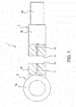
- a piston rod 1 is manufactured by joining a rod main body 2 and a rod head 3 by friction welding.
- the piston rod 1 is inserted into a cylinder main body of a fluid pressure cylinder used as an actuator (not shown) so as to be freely movable back and forth.
- the rod main body 2 and the rod head 3 are manufactured by processing solid carbon steel manufactured by continuous casting. Steel having a carbon content of 0.45%, for example, is used as the carbon steel.
- FIG. 1 is a plan view showing the rod main body 2 and the rod head 3 prior to a manufacturing process of the piston rod 1 (prior to the friction welding).
- the rod main body 2 has a small-diameter portion 2a linked to a piston (not shown) that slides in the cylinder main body and a solid large-diameter portion 2b having a larger diameter than the small-diameter portion 2a.
- a planar end surface 2c is formed on the large-diameter portion 2b of the rod main body 2.
- the rod head 3 has an annular clevis 3a that is connected to a load and a solid body portion 3b having the same diameter as the large-diameter portion 2b of the rod main body 2.
- a planar end surface 3c is formed on the body portion 3b.
- the piston rod 1 is manufactured by integrally joining the end surface 2c of the solid large-diameter portion 2b of the rod main body 2 and the end surface 3c of the solid body portion 3b of the rod head 3 by the friction welding.
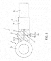
- the rod main body 2 and the rod head 3 are manufactured by processing a solid steel material manufactured by continuous casting. Impurities contained in molten steel are more likely to remain in liquid than in solid, and therefore, during the continuous casting, impurities tend to accumulate in an axial center portion that solidifies last. Thus, impurities caused by center segregation exist in the axial center portion of the steel material manufactured by continuous casting. Therefore, impurities caused by center segregation exist in an axial center portion of the rod main body 2 and an axial center portion of the body portion 3b of the rod head 3. In FIGs. 1 to 3 , impurities 10 are schematically illustrated by dotted lines.
- a first step the respective end surfaces 2c and 3c of the rod main body 2 and the rod head 3 are joined by the friction welding. Specific procedures of the friction welding that is the first step will be described below.
- the burrs 12 on the outer circumferential side of the piston rod 1 are removed, and the respective outer circumferences of the rod main body 2 and the rod head 3 are processed into a smooth continuous state.
- the burrs 12 on the outer circumferential side of the piston rod 1 may be removed after completion of the first step, or may be removed after completion of a second step, which will be described below.
- the removal of the burrs 12 needs not be performed, and the burrs 12 may remain on the outer circumferential side of the piston rod 1.
- a quality inspection by means of a nondestructive test such as an ultrasonic flaw inspection, is performed on a friction-welded portion between the rod main body 2 and the rod head 3.
- a boring process is performed, in which a hole 13 that penetrates from the rod head 3 side through the joining face 11 between the rod main body 2 and the rod head 3 is formed in the axial center portion.
- the boring process as the second step is performed by inserting a cutting tool, such as a drill, from the rod head 3 side so as to pass through the respective axial center portions of the rod head 3 and the rod main body 2.
- the cutting tool is inserted from the left side in FIG. 3 so as to pass through the axial center portion of the rod head 3 from the clevis 3a to the body portion 3b of the rod head 3.
- the cutting tool continues to advance and penetrates through the joining face 11.
- the cutting tool is inserted until it passes through the axial center portion of the rod main body 2 and reaches a predetermined depth.
- the boring process is performed by inserting the cutting tool so as to penetrate through the joining face 11 between the rod main body 2 and the rod head 3.
- An insertion depth of the cutting tool after penetrating through the joining face 11 is determined by performing a test or an inspection on the joined body consisting of the rod main body 2 and the rod head 3 formed in the first step. Specifically, by performing the test or the inspection on some of the joined bodies formed in the first step as samples, a depth of a portion that needs to be removed of a center segregation portion in which the impurities 10 have accumulated is determined. In addition, as to a hole diameter of the hole 13 formed by the boring process, similarly to the depth, an optimal diameter is selected in accordance with a result of the test or the inspection on the joined body.
- the second step including the boring process in which the center segregation is removed is performed after the first step in which the rod main body 2 and the rod head 3 are joined by the friction welding. Therefore, there is no bead on an inner circumference of the hole 13 of the piston rod 1. Thus, the stress does not concentrate on the inner circumferential side of the hole 13.
- the depth and the diameter of the hole 13 are determined in accordance with a result of the test or the inspection performed on the joined body formed in the first step with the rod main body 2 and the rod head 3. Therefore, even if the depth or the diameter of the center segregation portion that needs to be removed of the rod main body 2 and the rod head 3 is different due to variations in material lots, it is possible to reliably remove the center segregation portion of the axial center portion.
- An opening of the hole 13 formed in the second step may be sealed by using a plug etc.
- the boring process is performed on the axial center portion such that the hole penetrates through the joining face 11 from the rod head 3 side.
- the impurities 10 caused by center segregation.
- no stress is concentrated on the inner circumferential side of the hole 13. Therefore, it is possible to suppress deterioration of durability of the joined body.
- the piston rod 1 can be manufactured using an inexpensive, relatively low-quality material, it is possible to reduce a manufacturing cost.
Landscapes
- Engineering & Computer Science (AREA)
- Mechanical Engineering (AREA)
- General Engineering & Computer Science (AREA)
- Physics & Mathematics (AREA)
- Fluid Mechanics (AREA)
- Quality & Reliability (AREA)
- Pressure Welding/Diffusion-Bonding (AREA)
- Shafts, Cranks, Connecting Bars, And Related Bearings (AREA)
- Actuator (AREA)
- Pistons, Piston Rings, And Cylinders (AREA)
Claims (3)
- Ein Kolbenstangenherstellungsverfahren zum Herstellen einer Kolbenstange (1) durch Verbinden eines festen Stangenhauptkörpers (2) und eines festen Stangenkopfes (3) aufweisend einen ringförmigen Kopf (3a), der mit einer Last verbunden ist, und eines festen Körperabschnitts (3b), dadurch gekennzeichnet, dass dieses beinhaltet:einen ersten Schritt des Verbindens einer Endfläche (2a) des Stangenhauptkörpers (2) und einer Endfläche (3c) des Körperabschnitts (3b) des Stangenkopfes (3) durch Reibschweißen; undeinen zweiten Schritt zum Durchführen eines Bohrprozesses an einem axialen Zentrumsabschnitt von der Stangenkopfseite zum Hindurchtreten durch eine Verbindungsfläche zwischen dem Stangenhauptkörper (2) und dem Stangenkopf (3) von dem Kopf (3a) zum Körperabschnitt (3b); wobei der zweite Schritt nach dem ersten Schritt durchgeführt wird.
- Das Kolbenstangenherstellungsverfahren gemäß Anspruch 1, weiter aufweisend einen dritten Schritt zum Abdichten von zumindest einem entsprechender Löcher (13), die im Kopf (3a) und in dem Körperabschnitt (3b) in dem zweiten Schritt geformt sind mit einem Dichtungsglied.
- Das Kolbenstangenherstellungsverfahren gemäß Anspruch 1, weiter aufweisend einen Schritt zum Durchführen einer Qualitätsinspektion mittels eines nichtzerstörenden Tests an einem reibgeschweißten Abschnitt zwischen dem Stangenhauptkörper (2) und dem Stangenkopf (3) nach dem ersten Schritt und bevor dem zweiten Schritt.
Applications Claiming Priority (2)
| Application Number | Priority Date | Filing Date | Title |
|---|---|---|---|
| JP2013174759A JP5795785B2 (ja) | 2013-08-26 | 2013-08-26 | ピストンロッドの製造方法 |
| PCT/JP2014/071190 WO2015029762A1 (ja) | 2013-08-26 | 2014-08-11 | ピストンロッドの製造方法 |
Publications (3)
| Publication Number | Publication Date |
|---|---|
| EP3040587A1 EP3040587A1 (de) | 2016-07-06 |
| EP3040587A4 EP3040587A4 (de) | 2017-03-15 |
| EP3040587B1 true EP3040587B1 (de) | 2019-10-09 |
Family
ID=52586331
Family Applications (1)
| Application Number | Title | Priority Date | Filing Date |
|---|---|---|---|
| EP14840755.4A Active EP3040587B1 (de) | 2013-08-26 | 2014-08-11 | Verfahren zur herstellung einer kolbenstange |
Country Status (6)
| Country | Link |
|---|---|
| US (1) | US9873165B2 (de) |
| EP (1) | EP3040587B1 (de) |
| JP (1) | JP5795785B2 (de) |
| KR (1) | KR101805326B1 (de) |
| CN (1) | CN105473908B (de) |
| WO (1) | WO2015029762A1 (de) |
Families Citing this family (6)
| Publication number | Priority date | Publication date | Assignee | Title |
|---|---|---|---|---|
| JP6071132B2 (ja) * | 2013-03-28 | 2017-02-01 | Kyb株式会社 | 接合体 |
| CN107498273A (zh) * | 2017-08-04 | 2017-12-22 | 原平市恒泰隆机械有限公司 | 一种活塞杆的不锈钢焊接及车削工艺 |
| DE112019004864T5 (de) * | 2018-09-27 | 2021-06-10 | Kyb-Ys Co., Ltd. | Herstellungsverfahren eines Verbindungskörpers |
| JP7229380B2 (ja) * | 2019-09-26 | 2023-02-27 | 日立Astemo株式会社 | ロッドの製造方法 |
| CN111590040B (zh) * | 2020-04-16 | 2022-04-01 | 攀钢集团攀枝花钢铁研究院有限公司 | 一种提升齿轮钢质量的小方坯连铸生产方法 |
| US11654506B2 (en) * | 2021-10-22 | 2023-05-23 | Halliburton Energy Services, Inc. | Processing route to design and manufacture highly configurable non-magnetic down-hole sensor collars |
Family Cites Families (9)
| Publication number | Priority date | Publication date | Assignee | Title |
|---|---|---|---|---|
| US3399801A (en) * | 1967-09-06 | 1968-09-03 | John H. Bent | Expansible plug for fluid systems |
| JPS61123488A (ja) * | 1984-11-20 | 1986-06-11 | Yamaha Motor Co Ltd | シリンダスリ−ブの製造方法 |
| US20100163601A1 (en) * | 2008-12-31 | 2010-07-01 | General Electric Company | Friction weld vibration quality monitoring system |
| GB0903101D0 (en) * | 2009-02-25 | 2009-04-08 | Rolls Royce Plc | A method of welding tubular components |
| JP2011056531A (ja) | 2009-09-09 | 2011-03-24 | Kyb Co Ltd | ピストンロッドの製造方法 |
| DE102009059055A1 (de) * | 2009-12-18 | 2011-06-22 | MAHLE International GmbH, 70376 | Reibschweißverfahren, Reibschweißverbindung sowie Kolben für einen Verbrennungsmotor |
| CN201714894U (zh) * | 2010-07-05 | 2011-01-19 | 南阳淅减汽车减振器有限公司 | 一种减振器活塞杆总成 |
| DE102011103883A1 (de) * | 2011-06-10 | 2012-12-13 | Robert Bosch Gmbh | Verfahren zur Herstellung eines Kolbens und Kolben für eine Kolbenmaschine |
| CN103062399A (zh) * | 2013-01-15 | 2013-04-24 | 哈尔滨东安液压机械股份有限公司 | 减速顶用组合结构摩擦焊接活塞毛料 |
-
2013
- 2013-08-26 JP JP2013174759A patent/JP5795785B2/ja active Active
-
2014
- 2014-08-11 CN CN201480046515.3A patent/CN105473908B/zh active Active
- 2014-08-11 EP EP14840755.4A patent/EP3040587B1/de active Active
- 2014-08-11 WO PCT/JP2014/071190 patent/WO2015029762A1/ja active Application Filing
- 2014-08-11 US US14/914,006 patent/US9873165B2/en active Active
- 2014-08-11 KR KR1020167004308A patent/KR101805326B1/ko active IP Right Grant
Non-Patent Citations (1)
| Title |
|---|
| None * |
Also Published As
| Publication number | Publication date |
|---|---|
| CN105473908A (zh) | 2016-04-06 |
| KR20160033204A (ko) | 2016-03-25 |
| US9873165B2 (en) | 2018-01-23 |
| US20160199951A1 (en) | 2016-07-14 |
| JP2015042891A (ja) | 2015-03-05 |
| KR101805326B1 (ko) | 2017-12-05 |
| CN105473908B (zh) | 2017-12-01 |
| JP5795785B2 (ja) | 2015-10-14 |
| EP3040587A4 (de) | 2017-03-15 |
| WO2015029762A1 (ja) | 2015-03-05 |
| EP3040587A1 (de) | 2016-07-06 |
Similar Documents
| Publication | Publication Date | Title |
|---|---|---|
| EP3040587B1 (de) | Verfahren zur herstellung einer kolbenstange | |
| EP2257403B1 (de) | Reibbolzenschweissverfahren und systeme | |
| WO2011030595A1 (ja) | ピストンロッドの製造方法 | |
| JP6215156B2 (ja) | 中空エンジンバルブ及びその製造方法 | |
| CN102211248A (zh) | 一种石油钻杆接头、钻杆及惯性摩擦焊接工艺和工装 | |
| US7988032B2 (en) | Method of welding tubular components | |
| JP2015042891A5 (de) | ||
| KR20120046014A (ko) | 디스크 브레이크 | |
| JP6071132B2 (ja) | 接合体 | |
| KR20110087042A (ko) | 자동차용 추진축의 슬립요크 제조방법 | |
| KR100889472B1 (ko) | 관재 고압 액압성형을 이용한 다중복합강관 및 그 제조방법 | |
| CN104295326A (zh) | 用于涡轮增压器可变截面喷嘴环上的定距套的铆接结构 | |
| JP6718326B2 (ja) | 管台の溶接方法、管台の検査方法及び管台の製造方法 | |
| US9382820B2 (en) | Method for producing a built hollow valve | |
| JP2016068127A (ja) | 接合方法及び接合体 | |
| CN204113353U (zh) | 用于涡轮增压器可变截面喷嘴环上的定距套的铆接结构 | |
| EP2644909B1 (de) | Niethülse, Blindnietanordnung und Verfahren zum Lösen desselben | |
| JP6009417B2 (ja) | 中空エンジンバルブの製造方法 | |
| CN204300022U (zh) | 一种焊接油缸 | |
| JP2008087007A (ja) | 摩擦圧接された接続箇所を有する製品およびその製造方法 |
Legal Events
| Date | Code | Title | Description |
|---|---|---|---|
| PUAI | Public reference made under article 153(3) epc to a published international application that has entered the european phase |
Free format text: ORIGINAL CODE: 0009012 |
|
| 17P | Request for examination filed |
Effective date: 20160222 |
|
| AK | Designated contracting states |
Kind code of ref document: A1 Designated state(s): AL AT BE BG CH CY CZ DE DK EE ES FI FR GB GR HR HU IE IS IT LI LT LU LV MC MK MT NL NO PL PT RO RS SE SI SK SM TR |
|
| AX | Request for extension of the european patent |
Extension state: BA ME |
|
| DAX | Request for extension of the european patent (deleted) | ||
| A4 | Supplementary search report drawn up and despatched |
Effective date: 20170209 |
|
| RIC1 | Information provided on ipc code assigned before grant |
Ipc: B23K 101/00 20060101ALI20170203BHEP Ipc: F16C 7/02 20060101ALI20170203BHEP Ipc: B23K 31/12 20060101ALI20170203BHEP Ipc: B23K 20/12 20060101ALI20170203BHEP Ipc: B23P 15/10 20060101ALI20170203BHEP Ipc: F15B 15/14 20060101ALI20170203BHEP Ipc: F16J 7/00 20060101AFI20170203BHEP |
|
| STAA | Information on the status of an ep patent application or granted ep patent |
Free format text: STATUS: EXAMINATION IS IN PROGRESS |
|
| 17Q | First examination report despatched |
Effective date: 20170801 |
|
| GRAP | Despatch of communication of intention to grant a patent |
Free format text: ORIGINAL CODE: EPIDOSNIGR1 |
|
| STAA | Information on the status of an ep patent application or granted ep patent |
Free format text: STATUS: GRANT OF PATENT IS INTENDED |
|
| INTG | Intention to grant announced |
Effective date: 20190528 |
|
| GRAS | Grant fee paid |
Free format text: ORIGINAL CODE: EPIDOSNIGR3 |
|
| GRAA | (expected) grant |
Free format text: ORIGINAL CODE: 0009210 |
|
| STAA | Information on the status of an ep patent application or granted ep patent |
Free format text: STATUS: THE PATENT HAS BEEN GRANTED |
|
| AK | Designated contracting states |
Kind code of ref document: B1 Designated state(s): AL AT BE BG CH CY CZ DE DK EE ES FI FR GB GR HR HU IE IS IT LI LT LU LV MC MK MT NL NO PL PT RO RS SE SI SK SM TR |
|
| REG | Reference to a national code |
Ref country code: GB Ref legal event code: FG4D |
|
| REG | Reference to a national code |
Ref country code: CH Ref legal event code: EP |
|
| REG | Reference to a national code |
Ref country code: IE Ref legal event code: FG4D |
|
| REG | Reference to a national code |
Ref country code: DE Ref legal event code: R096 Ref document number: 602014055039 Country of ref document: DE |
|
| REG | Reference to a national code |
Ref country code: AT Ref legal event code: REF Ref document number: 1189216 Country of ref document: AT Kind code of ref document: T Effective date: 20191115 |
|
| REG | Reference to a national code |
Ref country code: NL Ref legal event code: MP Effective date: 20191009 |
|
| REG | Reference to a national code |
Ref country code: LT Ref legal event code: MG4D |
|
| REG | Reference to a national code |
Ref country code: AT Ref legal event code: MK05 Ref document number: 1189216 Country of ref document: AT Kind code of ref document: T Effective date: 20191009 |
|
| PG25 | Lapsed in a contracting state [announced via postgrant information from national office to epo] |
Ref country code: NO Free format text: LAPSE BECAUSE OF FAILURE TO SUBMIT A TRANSLATION OF THE DESCRIPTION OR TO PAY THE FEE WITHIN THE PRESCRIBED TIME-LIMIT Effective date: 20200109 Ref country code: PL Free format text: LAPSE BECAUSE OF FAILURE TO SUBMIT A TRANSLATION OF THE DESCRIPTION OR TO PAY THE FEE WITHIN THE PRESCRIBED TIME-LIMIT Effective date: 20191009 Ref country code: FI Free format text: LAPSE BECAUSE OF FAILURE TO SUBMIT A TRANSLATION OF THE DESCRIPTION OR TO PAY THE FEE WITHIN THE PRESCRIBED TIME-LIMIT Effective date: 20191009 Ref country code: BG Free format text: LAPSE BECAUSE OF FAILURE TO SUBMIT A TRANSLATION OF THE DESCRIPTION OR TO PAY THE FEE WITHIN THE PRESCRIBED TIME-LIMIT Effective date: 20200109 Ref country code: LT Free format text: LAPSE BECAUSE OF FAILURE TO SUBMIT A TRANSLATION OF THE DESCRIPTION OR TO PAY THE FEE WITHIN THE PRESCRIBED TIME-LIMIT Effective date: 20191009 Ref country code: AT Free format text: LAPSE BECAUSE OF FAILURE TO SUBMIT A TRANSLATION OF THE DESCRIPTION OR TO PAY THE FEE WITHIN THE PRESCRIBED TIME-LIMIT Effective date: 20191009 Ref country code: NL Free format text: LAPSE BECAUSE OF FAILURE TO SUBMIT A TRANSLATION OF THE DESCRIPTION OR TO PAY THE FEE WITHIN THE PRESCRIBED TIME-LIMIT Effective date: 20191009 Ref country code: PT Free format text: LAPSE BECAUSE OF FAILURE TO SUBMIT A TRANSLATION OF THE DESCRIPTION OR TO PAY THE FEE WITHIN THE PRESCRIBED TIME-LIMIT Effective date: 20200210 Ref country code: GR Free format text: LAPSE BECAUSE OF FAILURE TO SUBMIT A TRANSLATION OF THE DESCRIPTION OR TO PAY THE FEE WITHIN THE PRESCRIBED TIME-LIMIT Effective date: 20200110 Ref country code: ES Free format text: LAPSE BECAUSE OF FAILURE TO SUBMIT A TRANSLATION OF THE DESCRIPTION OR TO PAY THE FEE WITHIN THE PRESCRIBED TIME-LIMIT Effective date: 20191009 Ref country code: SE Free format text: LAPSE BECAUSE OF FAILURE TO SUBMIT A TRANSLATION OF THE DESCRIPTION OR TO PAY THE FEE WITHIN THE PRESCRIBED TIME-LIMIT Effective date: 20191009 Ref country code: LV Free format text: LAPSE BECAUSE OF FAILURE TO SUBMIT A TRANSLATION OF THE DESCRIPTION OR TO PAY THE FEE WITHIN THE PRESCRIBED TIME-LIMIT Effective date: 20191009 |
|
| PG25 | Lapsed in a contracting state [announced via postgrant information from national office to epo] |
Ref country code: HR Free format text: LAPSE BECAUSE OF FAILURE TO SUBMIT A TRANSLATION OF THE DESCRIPTION OR TO PAY THE FEE WITHIN THE PRESCRIBED TIME-LIMIT Effective date: 20191009 Ref country code: RS Free format text: LAPSE BECAUSE OF FAILURE TO SUBMIT A TRANSLATION OF THE DESCRIPTION OR TO PAY THE FEE WITHIN THE PRESCRIBED TIME-LIMIT Effective date: 20191009 Ref country code: IS Free format text: LAPSE BECAUSE OF FAILURE TO SUBMIT A TRANSLATION OF THE DESCRIPTION OR TO PAY THE FEE WITHIN THE PRESCRIBED TIME-LIMIT Effective date: 20200224 |
|
| PG25 | Lapsed in a contracting state [announced via postgrant information from national office to epo] |
Ref country code: AL Free format text: LAPSE BECAUSE OF FAILURE TO SUBMIT A TRANSLATION OF THE DESCRIPTION OR TO PAY THE FEE WITHIN THE PRESCRIBED TIME-LIMIT Effective date: 20191009 |
|
| REG | Reference to a national code |
Ref country code: DE Ref legal event code: R097 Ref document number: 602014055039 Country of ref document: DE |
|
| PG2D | Information on lapse in contracting state deleted |
Ref country code: IS |
|
| PG25 | Lapsed in a contracting state [announced via postgrant information from national office to epo] |
Ref country code: CZ Free format text: LAPSE BECAUSE OF FAILURE TO SUBMIT A TRANSLATION OF THE DESCRIPTION OR TO PAY THE FEE WITHIN THE PRESCRIBED TIME-LIMIT Effective date: 20191009 Ref country code: RO Free format text: LAPSE BECAUSE OF FAILURE TO SUBMIT A TRANSLATION OF THE DESCRIPTION OR TO PAY THE FEE WITHIN THE PRESCRIBED TIME-LIMIT Effective date: 20191009 Ref country code: DK Free format text: LAPSE BECAUSE OF FAILURE TO SUBMIT A TRANSLATION OF THE DESCRIPTION OR TO PAY THE FEE WITHIN THE PRESCRIBED TIME-LIMIT Effective date: 20191009 Ref country code: EE Free format text: LAPSE BECAUSE OF FAILURE TO SUBMIT A TRANSLATION OF THE DESCRIPTION OR TO PAY THE FEE WITHIN THE PRESCRIBED TIME-LIMIT Effective date: 20191009 Ref country code: IS Free format text: LAPSE BECAUSE OF FAILURE TO SUBMIT A TRANSLATION OF THE DESCRIPTION OR TO PAY THE FEE WITHIN THE PRESCRIBED TIME-LIMIT Effective date: 20200209 |
|
| PLBE | No opposition filed within time limit |
Free format text: ORIGINAL CODE: 0009261 |
|
| STAA | Information on the status of an ep patent application or granted ep patent |
Free format text: STATUS: NO OPPOSITION FILED WITHIN TIME LIMIT |
|
| PG25 | Lapsed in a contracting state [announced via postgrant information from national office to epo] |
Ref country code: SK Free format text: LAPSE BECAUSE OF FAILURE TO SUBMIT A TRANSLATION OF THE DESCRIPTION OR TO PAY THE FEE WITHIN THE PRESCRIBED TIME-LIMIT Effective date: 20191009 Ref country code: SM Free format text: LAPSE BECAUSE OF FAILURE TO SUBMIT A TRANSLATION OF THE DESCRIPTION OR TO PAY THE FEE WITHIN THE PRESCRIBED TIME-LIMIT Effective date: 20191009 |
|
| 26N | No opposition filed |
Effective date: 20200710 |
|
| PG25 | Lapsed in a contracting state [announced via postgrant information from national office to epo] |
Ref country code: SI Free format text: LAPSE BECAUSE OF FAILURE TO SUBMIT A TRANSLATION OF THE DESCRIPTION OR TO PAY THE FEE WITHIN THE PRESCRIBED TIME-LIMIT Effective date: 20191009 |
|
| REG | Reference to a national code |
Ref country code: DE Ref legal event code: R119 Ref document number: 602014055039 Country of ref document: DE |
|
| PG25 | Lapsed in a contracting state [announced via postgrant information from national office to epo] |
Ref country code: MC Free format text: LAPSE BECAUSE OF FAILURE TO SUBMIT A TRANSLATION OF THE DESCRIPTION OR TO PAY THE FEE WITHIN THE PRESCRIBED TIME-LIMIT Effective date: 20191009 |
|
| REG | Reference to a national code |
Ref country code: CH Ref legal event code: PL |
|
| GBPC | Gb: european patent ceased through non-payment of renewal fee |
Effective date: 20200811 |
|
| PG25 | Lapsed in a contracting state [announced via postgrant information from national office to epo] |
Ref country code: CH Free format text: LAPSE BECAUSE OF NON-PAYMENT OF DUE FEES Effective date: 20200831 Ref country code: LI Free format text: LAPSE BECAUSE OF NON-PAYMENT OF DUE FEES Effective date: 20200831 Ref country code: LU Free format text: LAPSE BECAUSE OF NON-PAYMENT OF DUE FEES Effective date: 20200811 |
|
| REG | Reference to a national code |
Ref country code: BE Ref legal event code: MM Effective date: 20200831 |
|
| PG25 | Lapsed in a contracting state [announced via postgrant information from national office to epo] |
Ref country code: DE Free format text: LAPSE BECAUSE OF NON-PAYMENT OF DUE FEES Effective date: 20210302 Ref country code: FR Free format text: LAPSE BECAUSE OF NON-PAYMENT OF DUE FEES Effective date: 20200831 |
|
| PG25 | Lapsed in a contracting state [announced via postgrant information from national office to epo] |
Ref country code: IE Free format text: LAPSE BECAUSE OF NON-PAYMENT OF DUE FEES Effective date: 20200811 Ref country code: GB Free format text: LAPSE BECAUSE OF NON-PAYMENT OF DUE FEES Effective date: 20200811 Ref country code: BE Free format text: LAPSE BECAUSE OF NON-PAYMENT OF DUE FEES Effective date: 20200831 |
|
| PG25 | Lapsed in a contracting state [announced via postgrant information from national office to epo] |
Ref country code: TR Free format text: LAPSE BECAUSE OF FAILURE TO SUBMIT A TRANSLATION OF THE DESCRIPTION OR TO PAY THE FEE WITHIN THE PRESCRIBED TIME-LIMIT Effective date: 20191009 Ref country code: MT Free format text: LAPSE BECAUSE OF FAILURE TO SUBMIT A TRANSLATION OF THE DESCRIPTION OR TO PAY THE FEE WITHIN THE PRESCRIBED TIME-LIMIT Effective date: 20191009 Ref country code: CY Free format text: LAPSE BECAUSE OF FAILURE TO SUBMIT A TRANSLATION OF THE DESCRIPTION OR TO PAY THE FEE WITHIN THE PRESCRIBED TIME-LIMIT Effective date: 20191009 |
|
| PG25 | Lapsed in a contracting state [announced via postgrant information from national office to epo] |
Ref country code: MK Free format text: LAPSE BECAUSE OF FAILURE TO SUBMIT A TRANSLATION OF THE DESCRIPTION OR TO PAY THE FEE WITHIN THE PRESCRIBED TIME-LIMIT Effective date: 20191009 |
|
| PGFP | Annual fee paid to national office [announced via postgrant information from national office to epo] |
Ref country code: IT Payment date: 20230825 Year of fee payment: 10 |