EP3036562B1 - Devices and methods for a rotating lidar platform with a shared transmit/receive path - Google Patents
Devices and methods for a rotating lidar platform with a shared transmit/receive path Download PDFInfo
- Publication number
- EP3036562B1 EP3036562B1 EP14838560.2A EP14838560A EP3036562B1 EP 3036562 B1 EP3036562 B1 EP 3036562B1 EP 14838560 A EP14838560 A EP 14838560A EP 3036562 B1 EP3036562 B1 EP 3036562B1
- Authority
- EP
- European Patent Office
- Prior art keywords
- light
- lens
- block
- receive
- transmit
- Prior art date
- Legal status (The legal status is an assumption and is not a legal conclusion. Google has not performed a legal analysis and makes no representation as to the accuracy of the status listed.)
- Active
Links
Images


Classifications
-
- G—PHYSICS
- G01—MEASURING; TESTING
- G01S—RADIO DIRECTION-FINDING; RADIO NAVIGATION; DETERMINING DISTANCE OR VELOCITY BY USE OF RADIO WAVES; LOCATING OR PRESENCE-DETECTING BY USE OF THE REFLECTION OR RERADIATION OF RADIO WAVES; ANALOGOUS ARRANGEMENTS USING OTHER WAVES
- G01S7/00—Details of systems according to groups G01S13/00, G01S15/00, G01S17/00
- G01S7/48—Details of systems according to groups G01S13/00, G01S15/00, G01S17/00 of systems according to group G01S17/00
- G01S7/481—Constructional features, e.g. arrangements of optical elements
- G01S7/4811—Constructional features, e.g. arrangements of optical elements common to transmitter and receiver
- G01S7/4813—Housing arrangements
-
- G—PHYSICS
- G01—MEASURING; TESTING
- G01S—RADIO DIRECTION-FINDING; RADIO NAVIGATION; DETERMINING DISTANCE OR VELOCITY BY USE OF RADIO WAVES; LOCATING OR PRESENCE-DETECTING BY USE OF THE REFLECTION OR RERADIATION OF RADIO WAVES; ANALOGOUS ARRANGEMENTS USING OTHER WAVES
- G01S7/00—Details of systems according to groups G01S13/00, G01S15/00, G01S17/00
- G01S7/48—Details of systems according to groups G01S13/00, G01S15/00, G01S17/00 of systems according to group G01S17/00
- G01S7/481—Constructional features, e.g. arrangements of optical elements
-
- G—PHYSICS
- G01—MEASURING; TESTING
- G01S—RADIO DIRECTION-FINDING; RADIO NAVIGATION; DETERMINING DISTANCE OR VELOCITY BY USE OF RADIO WAVES; LOCATING OR PRESENCE-DETECTING BY USE OF THE REFLECTION OR RERADIATION OF RADIO WAVES; ANALOGOUS ARRANGEMENTS USING OTHER WAVES
- G01S17/00—Systems using the reflection or reradiation of electromagnetic waves other than radio waves, e.g. lidar systems
- G01S17/02—Systems using the reflection of electromagnetic waves other than radio waves
- G01S17/06—Systems determining position data of a target
- G01S17/42—Simultaneous measurement of distance and other co-ordinates
-
- G—PHYSICS
- G01—MEASURING; TESTING
- G01S—RADIO DIRECTION-FINDING; RADIO NAVIGATION; DETERMINING DISTANCE OR VELOCITY BY USE OF RADIO WAVES; LOCATING OR PRESENCE-DETECTING BY USE OF THE REFLECTION OR RERADIATION OF RADIO WAVES; ANALOGOUS ARRANGEMENTS USING OTHER WAVES
- G01S17/00—Systems using the reflection or reradiation of electromagnetic waves other than radio waves, e.g. lidar systems
- G01S17/88—Lidar systems specially adapted for specific applications
- G01S17/89—Lidar systems specially adapted for specific applications for mapping or imaging
-
- G—PHYSICS
- G01—MEASURING; TESTING
- G01S—RADIO DIRECTION-FINDING; RADIO NAVIGATION; DETERMINING DISTANCE OR VELOCITY BY USE OF RADIO WAVES; LOCATING OR PRESENCE-DETECTING BY USE OF THE REFLECTION OR RERADIATION OF RADIO WAVES; ANALOGOUS ARRANGEMENTS USING OTHER WAVES
- G01S17/00—Systems using the reflection or reradiation of electromagnetic waves other than radio waves, e.g. lidar systems
- G01S17/88—Lidar systems specially adapted for specific applications
- G01S17/93—Lidar systems specially adapted for specific applications for anti-collision purposes
- G01S17/931—Lidar systems specially adapted for specific applications for anti-collision purposes of land vehicles
-
- G—PHYSICS
- G01—MEASURING; TESTING
- G01S—RADIO DIRECTION-FINDING; RADIO NAVIGATION; DETERMINING DISTANCE OR VELOCITY BY USE OF RADIO WAVES; LOCATING OR PRESENCE-DETECTING BY USE OF THE REFLECTION OR RERADIATION OF RADIO WAVES; ANALOGOUS ARRANGEMENTS USING OTHER WAVES
- G01S7/00—Details of systems according to groups G01S13/00, G01S15/00, G01S17/00
- G01S7/48—Details of systems according to groups G01S13/00, G01S15/00, G01S17/00 of systems according to group G01S17/00
- G01S7/481—Constructional features, e.g. arrangements of optical elements
- G01S7/4811—Constructional features, e.g. arrangements of optical elements common to transmitter and receiver
- G01S7/4812—Constructional features, e.g. arrangements of optical elements common to transmitter and receiver transmitted and received beams following a coaxial path
-
- G—PHYSICS
- G01—MEASURING; TESTING
- G01S—RADIO DIRECTION-FINDING; RADIO NAVIGATION; DETERMINING DISTANCE OR VELOCITY BY USE OF RADIO WAVES; LOCATING OR PRESENCE-DETECTING BY USE OF THE REFLECTION OR RERADIATION OF RADIO WAVES; ANALOGOUS ARRANGEMENTS USING OTHER WAVES
- G01S7/00—Details of systems according to groups G01S13/00, G01S15/00, G01S17/00
- G01S7/48—Details of systems according to groups G01S13/00, G01S15/00, G01S17/00 of systems according to group G01S17/00
- G01S7/481—Constructional features, e.g. arrangements of optical elements
- G01S7/4814—Constructional features, e.g. arrangements of optical elements of transmitters alone
- G01S7/4815—Constructional features, e.g. arrangements of optical elements of transmitters alone using multiple transmitters
-
- G—PHYSICS
- G01—MEASURING; TESTING
- G01S—RADIO DIRECTION-FINDING; RADIO NAVIGATION; DETERMINING DISTANCE OR VELOCITY BY USE OF RADIO WAVES; LOCATING OR PRESENCE-DETECTING BY USE OF THE REFLECTION OR RERADIATION OF RADIO WAVES; ANALOGOUS ARRANGEMENTS USING OTHER WAVES
- G01S7/00—Details of systems according to groups G01S13/00, G01S15/00, G01S17/00
- G01S7/48—Details of systems according to groups G01S13/00, G01S15/00, G01S17/00 of systems according to group G01S17/00
- G01S7/481—Constructional features, e.g. arrangements of optical elements
- G01S7/4816—Constructional features, e.g. arrangements of optical elements of receivers alone
-
- G—PHYSICS
- G01—MEASURING; TESTING
- G01S—RADIO DIRECTION-FINDING; RADIO NAVIGATION; DETERMINING DISTANCE OR VELOCITY BY USE OF RADIO WAVES; LOCATING OR PRESENCE-DETECTING BY USE OF THE REFLECTION OR RERADIATION OF RADIO WAVES; ANALOGOUS ARRANGEMENTS USING OTHER WAVES
- G01S7/00—Details of systems according to groups G01S13/00, G01S15/00, G01S17/00
- G01S7/48—Details of systems according to groups G01S13/00, G01S15/00, G01S17/00 of systems according to group G01S17/00
- G01S7/481—Constructional features, e.g. arrangements of optical elements
- G01S7/4817—Constructional features, e.g. arrangements of optical elements relating to scanning
Definitions
- Vehicles can be configured to operate in an autonomous mode in which the vehicle navigates through an environment with little or no input from a driver.
- Such autonomous vehicles can include one or more sensors that are configured to detect information about the environment in which the vehicle operates.
- a LIDAR can estimates distance to environmental features while scanning through a scene to assemble a "point cloud" indicative of reflective surfaces in the environment. Individual points in the point cloud can be determined by transmitting a laser pulse and detecting a returning pulse, if any, reflected from an object in the environment, and determining the distance to the object according to the time delay between the transmitted pulse and the reception of the reflected pulse.
- a laser, or set of lasers can be rapidly and repeatedly scanned across a scene to provide continuous real-time information on distances to reflective objects in the scene. Combining the measured distances and the orientation of the laser(s) while measuring each distance allows for associating a three-dimensional position with each returning pulse.
- US patent application publication number US 2011/216304 A1 presents a LiDAR-based 3-D point cloud measuring system which includes a base, a housing, a plurality of photon transmitters and photon detectors contained within the housing, a rotary motor that rotates the housing about the base, and a communication component that allows transmission of signals generated by the photon detectors to external components.
- US patent application publication number US 2010/302528 A1 presents a color LiDAR scanner device which includes color laser diodes (red, green, blue) and avalanche photodetector diodes (red, green, blue) that illuminate and detect the color light intensity returned from a target.
- US patent application publication number US 2012/013917 A1 presents a measuring device, comprising a light source unit for projecting a pulsed distance measuring light toward an object to be measured, a projecting light optical system for projecting the pulsed distance measuring light emitted from the light source unit on the object to be measured, a light receiving optical system for receiving a reflected pulsed distance measuring light from the object to be measured, a light receiving part having a single photodetector for detecting the reflected pulsed distance measuring light as received, and a control unit for measuring a distance by measuring time from light emission of the pulsed distance measuring light to receipt of the reflected pulsed distance measuring light based on a detection signal from the photodetector.
- a light detection and ranging (LIDAR) device in one example, includes a housing configured to rotate about an axis.
- the housing has an interior space that includes a transmit block, a receive block, and a shared space.
- the transmit block has an exit aperture and the receive block has an entrance aperture.
- the LIDAR device also includes a plurality of light sources in the transmit block.
- the plurality of light sources is configured to emit a plurality of light beams that enter the shared space through the exit aperture and traverse the shared space via a transmit path.
- the light beams include light having wavelengths in a wavelength range.
- the LIDAR device also includes a plurality of detectors in the receive block. The plurality of detectors is configured to detect light having wavelengths in the wavelength range.
- the LIDAR device also includes a lens mounted to the housing.
- the lens is configured to (i) receive the light beams via the transmit path, (ii) collimate the light beams for transmission into an environment of the LIDAR device, (iii) collect light that includes light from one or more of the collimated light beams reflected by one or more objects in the environment of the LIDAR device, and (iv) focus the collected light onto the detectors via a receive path that extends through the shared space and the entrance aperture of the receive block.
- a method in another example, involves rotating a housing of a light detection and ranging (LIDAR) device about an axis.
- the housing has an interior space that includes a transmit block, a receive block, and a shared space.
- the transmit block has an exit aperture and the receive block has an entrance aperture.
- the method further involves emitting a plurality of light beams by a plurality of light sources in the transmit block.
- the plurality of light beams enter the shared space via a transmit path.
- the light beams include light having wavelengths in a wavelength range.
- the method further involves receiving the light beams at a lens mounted to the housing along the transmit path.
- the method further involves collimating, by the lens, the light beams for transmission into an environment of the LIDAR device.
- the method further involves collecting, by the lens, light from one or more of the collimated light beams reflected by one or more objects in the environment of the LIDAR device.
- the method further involves focusing, by the lens, the collected light onto a plurality of detectors in the receive block via a receive path that extends through the shared space and the entrance aperture of the receive block.
- the method further involves detecting, by the plurality of detectors in the receive block, light from the focused light having wavelengths in the wavelength range.
- a light detection and ranging (LIDAR) device may transmit light pulses originating from a plurality of light sources and may receive reflected light pulses that are then detected by a plurality of detectors.
- a LIDAR device is provided that includes a transmit/receive lens that both collimates the light from the plurality of light sources and focuses the reflected light onto the plurality of detectors.
- the LIDAR device comprises a housing that is configured to rotate about an axis.
- the axis is substantially vertical.
- the housing may have an interior space that includes various components such as a transmit block that includes the plurality of light sources, a receive block that includes the plurality of detectors, a shared space where emitted light traverses from the transmit block to the transmit/receive lens and reflected light traverses from the transmit/receive lens to the receive block, and the transmit/receive lens that collimates the emitted light and focuses the reflected light.
- the housing may include radio frequency (RF) and optical shielding between the transmit block and the receive block.
- RF radio frequency
- the housing can be formed from and/or coated by a metal, metallic ink, or metallic foam to provide the RF shielding.
- Metals used for shielding can include, for example, copper or nickel.
- the plurality of light sources included in the transmit block can include, for example, laser diodes.
- the light sources emit light with wavelengths of approximately 905 nm.
- a transmit path through which the transmit/receive lens receives the light emitted by the light sources may include a reflective element, such as a mirror or prism. By including the reflective element, the transmit path can be folded to provide a smaller size of the transmit block and, hence, a smaller housing of the LIDAR device.
- the transmit path includes an exit aperture of the transmit block through which the emitted light enters the shared space and traverses to the transmit/receive lens.
- each light source of the plurality of light sources includes a respective lens, such as a cylindrical or acylindrical lens.
- the light source may emit an uncollimated light beam that diverges more in a first direction than in a second direction.
- the light source's respective lens may pre-collimate the uncollimated light beam in the first direction to provide a partially collimated light beam, thereby reducing the divergence in the first direction.
- the partially collimated light beam diverges less in the first direction than in the second direction.
- the transmit/receive lens receives the partially collimated light beams from the one or more light sources via an exit aperture of the transmit block and the transmit/receive lens collimates the partially collimated light beams to provide collimated light beams that are transmitted into the environment of the LIDAR device.
- the light emitted by the light sources may have a greater divergence in the second direction than in the first direction, and the exit aperture can accommodate vertical and horizontal extents of the beams of light from the light sources.
- the housing mounts the transmit/receive lens through which light from the plurality of light sources can exit the housing, and reflected light can enter the housing to reach the receive block.
- the transmit/receive lens can have an optical power that is sufficient to collimate the light emitted by the plurality of light sources and to focus the reflected light onto the plurality of detectors in the receive block.
- the transmit/receive lens has a surface with an aspheric shape that is at the outside of the housing, a surface with a toroidal shape that is inside the housing, and a focal length of approximately 120 mm.
- the plurality of detectors included in the receive block can include, for example, avalanche photodiodes in a sealed environment that is filled with an inert gas, such as nitrogen.
- the receive block can include an entrance aperture through which focused light from the transmit/receive lens traverses towards the detectors.
- the entrance aperture can include a filtering window that passes light having wavelengths within the wavelength range emitted by the plurality of light sources and attenuates light having other wavelengths.
- the collimated light transmitted from the LIDAR device into the environment may reflect from one or more objects in the environment to provide object-reflected light.
- the transmit/receive lens may collect the object-reflected light and focus the object-reflected light through a focusing path ("receive path") onto the plurality of detectors.
- the receive path may include a reflective surface that directs the focused light to the plurality of detectors. Additionally or alternatively, the reflective surface can fold the focused light towards the receive block and thus provide space savings for the shared space and the housing of the LIDAR device.
- the reflective surface may define a wall that includes the exit aperture between the transmit block and the shared space.
- the exit aperture of the transmit block corresponds to a transparent and/or non-reflective portion of the reflective surface.
- the transparent portion can be a hole or cut-away portion of the reflective surface.
- the reflective surface can be formed by forming a layer of reflective material on a transparent substrate (e.g., glass) and the transparent portion can be a portion of the substrate that is not coated with the reflective material.
- the shared space can be used for both the transmit path and the receive path.
- the transmit path at least partially overlaps the receive path in the shared space.
- the vertical and horizontal extents of the exit aperture are sufficient to accommodate the beam widths of the emitted light beams from the light sources.
- the non-reflective nature of the exit aperture prevents a portion of the collected and focused light in the receive path from reflecting, at the reflective surface, towards the detectors in the receive block.
- reducing the beam widths of the emitted light beams from the transmit blocks is desirable to minimize the size of the exit aperture and reduce the lost portion of the collected light.
- the reduction of the beam widths traversing through the exit aperture can be achieved by partially collimating the emitted light beams by including a respective lens, such as a cylindrical or acylindrical lens, adjacent to each light source.
- the transmit/receive lens can be configured to define a focal surface that has a substantial curvature in a vertical plane and/or a horizontal plane.
- the transmit/receive lens can be configured to have the aspheric surface and the toroidal surface described above that provides the curved focal surface along the vertical plane and/or the horizontal plane.
- the light sources in the transmit block can be arranged along the transmit/receive lens' curved focal surface in the transmit block, and the detectors in the receive block can be arranged on the transmit/receive lens' curved focal surface in the receive block.
- the emitted light beams from the light sources arranged along the curved focal surface can converge into the exit aperture having a smaller size than an aperture for light beams that are substantially parallel and/or diverging.
- the light sources can be mounted on a curved edge of one or more vertically-oriented printed circuit boards (PCBs), such that the curved edge of the PCB substantially matches the curvature of the focal surface in the vertical plane of the PCB.
- the one or more PCBs can be mounted in the transmit block along a horizontal curvature that substantially matches the curvature of the focal surface in the horizontal plane of the one or more PCBs.
- the transmit block can include four PCBs, with each PCB mounting sixteen light sources, so as to provide 64 light sources along the curved focal plane of the transmit/receive lens in the transmit block.
- the 64 light sources are arranged in a pattern substantially corresponding to the curved focal surface defined by the transmit/receive lens such that the emitted light beams converge towards the exit aperture of the transmit block.
- the plurality of detectors can be disposed on a flexible PCB that is mounted to the receive block to conform with the shape of the transmit/receive lens' focal surface.
- the flexible PCB may be held between two clamping pieces that have surfaces corresponding to the shape of the focal surface.
- each of the plurality of detectors can be arranged on the flexible PCB so as to receive focused light from the transmit/receive lens that corresponds to a respective light source of the plurality of light sources.
- the detectors can be arranged in a pattern substantially corresponding to the curved focal surface of the transmit/receive lens in the receive block.
- the transmit/receive lens can be configured to focus onto each detector of the plurality of detectors a respective portion of the collected light that comprises light from the detector's corresponding light source.
- LIDAR device that uses a shared transmit/receive lens.
- LIDAR device can include the shared lens configured to provide a curved focal plane for transmitting light sources and receiving detectors such that light from the light sources passes through a small exit aperture included in a reflective surface that reflects collected light towards the detectors.
- FIG. 1 is a block diagram of an example LIDAR device 100.
- the LIDAR device 100 comprises a housing 110 that houses an arrangement of various components included in the LIDAR device 100 such as a transmit block 120, a receive block 130, a shared space 140, and a lens 150.
- the LIDAR device 100 includes the arrangement of the various components that provide emitted light beams 102 from the transmit block 120 that are collimated by the lens 150 and transmitted to an environment of the LIDAR device 100 as collimated light beams 104, and collect reflected light 106 from one or more objects in the environment of the LIDAR device 100 by the lens 150 for focusing towards the receive block 130 as focused light 108.
- the reflected light 106 comprises light from the collimated light beams 104 that was reflected by the one or more objects in the environment of the LIDAR device 100.
- the emitted light beams 102 and the focused light 108 traverse in the shared space 140 also included in the housing 110.
- the emitted light beams 102 are propagating in a transmit path through the shared space 140 and the focused light 108 are propagating in a receive path through the shared space 140.
- the transmit path at least partially overlaps the receive path in the shared space 140.
- the LIDAR device 100 can determine an aspect of the one or more objects (e.g., location, shape, etc.) in the environment of the LIDAR device 100 by processing the focused light 108 received by the receive block 130.
- the LIDAR device 100 can compare a time when pulses included in the emitted light beams 102 were emitted by the transmit block 120 with a time when corresponding pulses included in the focused light 108 were received by the receive block 130 and determine the distance between the one or more objects and the LIDAR device 100 based on the comparison.
- the housing 110 included in the LIDAR device 100 can provide a platform for mounting the various components included in the LIDAR device 100.
- the housing 110 can be formed from any material capable of supporting the various components of the LIDAR device 100 included in an interior space of the housing 110.
- the housing 110 may be formed from a structural material such as plastic or metal.
- the housing 110 can be configured for optical shielding to reduce ambient light and/or unintentional transmission of the emitted light beams 102 from the transmit block 120 to the receive block 130.
- Optical shielding from ambient light of the environment of the LIDAR device 100 can be achieved by forming and/or coating the outer surface of the housing 110 with a material that blocks the ambient light from the environment.
- inner surfaces of the housing 110 can include and/or be coated with the material described above to optically isolate the transmit block 120 from the receive block 130 to prevent the receive block 130 from receiving the emitted light beams 102 before the emitted light beams 102 reach the lens 150.
- the housing 110 can be configured for electromagnetic shielding to reduce electromagnetic noise (e.g., Radio Frequency (RF) Noise, etc.) from ambient environment of the LIDAR device 110 and/or electromagnetic noise between the transmit block 120 and the receive block 130.
- Electromagnetic shielding can improve quality of the emitted light beams 1 02 emitted by the transmit block 120 and reduce noise in signals received and/or provided by the receive block 130.
- Electromagnetic shielding can be achieved by forming and/or coating the housing 110 with a material that absorbs electromagnetic radiation such as a metal, metallic ink, metallic foam, carbon foam, or any other material configured to absorb electromagnetic radiation.
- Metals that can be used for the electromagnetic shielding can include for example, copper or nickel.
- the housing 110 can be configured to have a substantially cylindrical shape and to rotate about an axis of the LIDAR device 100.
- the housing 110 can have the substantially cylindrical shape with a diameter of approximately 10 centimeters.
- the axis is substantially vertical.
- a three-dimensional map of a 360 degree view of the environment of the LIDAR device 100 can be determined without frequent recalibration of the arrangement of the various components of the LIDAR device 100.
- the LIDAR device 100 can be configured to tilt the axis of rotation of the housing 110 to control the field of view of the LIDAR device 100.
- the LIDAR device 100 can optionally include a mounting structure for the housing 110.
- the mounting structure can include a motor or other means for rotating the housing 110 about the axis of the LIDAR device 100.
- the mounting structure can be included in a device and/or system other than the LIDAR device 100.
- the various components of the LIDAR device 100 such as the transmit block 120, receive block 130, and the lens 150 can be removably mounted to the housing 110 in predetermined positions to reduce burden of calibrating the arrangement of each component and/or subcomponents included in each component.
- the housing 110 provides the platform for the various components of the LIDAR device 100 for ease of assembly, maintenance, calibration, and manufacture of the LIDAR device 100.
- the transmit block 120 includes a plurality of light sources 122 that can be configured to emit the plurality of emitted light beams 102 via an exit aperture 124.
- each of the plurality of emitted light beams 102 corresponds to one of the plurality of light sources 122.
- the transmit block 120 can optionally include a mirror 126 along the transmit path of the emitted light beams 102 between the light sources 122 and the exit aperture 124.
- the light sources 122 can include laser diodes, light emitting diodes (LED), vertical cavity surface emitting lasers (VCSEL), organic light emitting diodes (OLED), polymer light emitting diodes (PLED), light emitting polymers (LEP), liquid crystal displays (LCD), microelectromechanical systems (MEMS), or any other device configured to selectively transmit, reflect, and/or emit light to provide the plurality of emitted light beams 102.
- the light sources 122 can be configured to emit the emitted light beams 102 in a wavelength range that can be detected by detectors 132 included in the receive block 130.
- the wavelength range could, for example, be in the ultraviolet, visible, and/or infrared portions of the electromagnetic spectrum.
- the wavelength range can be a narrow wavelength range, such as provided by lasers. In one example, the wavelength range includes wavelengths that are approximately 905nm.
- the light sources 122 can be configured to emit the emitted light beams 102 in the form of pulses. In some examples, the plurality of light sources 122 can be disposed on one or more substrates (e.g., printed circuit boards (PCB), flexible PCBs, etc.) and arranged to emit the plurality of light beams 102 towards the exit aperture 124.
- PCB printed circuit boards
- the plurality of light sources 122 can be configured to emit uncollimated light beams included in the emitted light beams 102.
- the emitted light beams 102 can diverge in one or more directions along the transmit path due to the uncollimated light beams emitted by the plurality of light sources 122.
- vertical and horizontal extents of the emitted light beams 102 at any position along the transmit path can be based on an extent of the divergence of the uncollimated light beams emitted by the plurality of light sources 122.
- the exit aperture 124 arranged along the transmit path of the emitted light beams 102 can be configured to accommodate the vertical and horizontal extents of the plurality of light beams 102 emitted by the plurality of light sources 122 at the exit aperture 124.
- the block diagram shown in Figure 1 is described in connection with functional modules for convenience in description. However, the functional modules in the block diagram of Figure 1 can be physically implemented in other locations.
- the exit aperture 124 can be physically included in both the transmit block 120 and the shared space 140.
- the transmit block 120 and the shared space 140 can be separated by a wall that includes the exit aperture 124. In this case, the exit aperture 124 can correspond to a transparent portion of the wall.
- the transparent portion can be a hole or cut-away portion of the wall.
- the wall can be formed from a transparent substrate (e.g., glass) coated with a non-transparent material, and the exit aperture 124 can be a portion of the substrate that is not coated with the non-transparent material.
- the wall separating the transmit block 120 and the shared space 140 can be arranged along the receive path of the focused light 108, and thus, the exit aperture 124 can be minimized to allow a larger portion of the focused light 108 to reach the wall.
- the wall can be coated with a reflective material (e.g., reflective surface 142 in shared space 140) and the receive path can include reflecting the focused light 108 by the reflective material towards the receive block 130. In this case, minimizing the size of the exit aperture 124 can allow a larger portion of the focused light 108 to reflect off the reflective material that the wall is coated with.
- each light source of the plurality of light sources 122 can include a cylindrical lens arranged adjacent to the light source.
- the light source may emit a corresponding uncollimated light beam that diverges more in a first direction than in a second direction.
- the cylindrical lens may pre-collimate the uncollimated light beam in the first direction to provide a partially collimated light beam, thereby reducing the divergence in the first direction.
- the partially collimated light beam diverges less in the first direction than in the second direction.
- uncollimated light beams from other light sources of the plurality of light sources 122 can have a reduced beam width in the first direction and thus the emitted light beams 102 can have a smaller divergence due to the partially collimated light beams.
- at least one of the vertical and horizontal extents of the exit aperture 124 can be reduced due to partially collimating the light beams 102.
- the light sources 122 can be arranged along a substantially curved surface defined by the transmit block 120.
- the curved surface can be configured such that the emitted light beams 102 converge towards the exit aperture 124, and thus the vertical and horizontal extents of the emitted light beams 102 at the exit aperture 124 can be reduced due to the arrangement of the light sources 122 along the curved surface of the transmit block 120.
- the curved surface of the transmit block 120 can include a curvature along the first direction of divergence of the emitted light beams 102 and a curvature along the second direction of divergence of the emitted light beams 102, such that the plurality of light beams 102 converge towards a central area in front of the plurality of light sources 122 along the transmit path.
- the light sources 122 can be disposed on a flexible substrate (e.g., flexible PCB) having a curvature along one or more directions.
- the curved flexible substrate can be curved along the first direction of divergence of the emitted light beams 102 and the second direction of divergence of the emitted light beams 102
- the light sources 122 can be disposed on a curved edge of one or more vertically-oriented printed circuit boards (PCBs), such that the curved edge of the PCB substantially matches the curvature of the first direction (e.g., the vertical plane of the PCB).
- PCBs vertically-oriented printed circuit boards
- the one or more PCBs can be mounted in the transmit block 120 along a horizontal curvature that substantially matches the curvature of the second direction (e.g., the horizontal plane of the one or more PCBs).
- the transmit block 120 can include four PCBs, with each PCB mounting sixteen light sources, so as to provide 64 light sources along the curved surface of the transmit block 120.
- the 64 light sources are arranged in a pattern such that the emitted light beams 102 converge towards the exit aperture 124 of the transmit block 120.
- the transmit block 120 can optionally include the mirror 126 along the transmit path of the emitted light beams 102 between the light sources 122 and the exit aperture 124. By including the mirror 126 in the transmit block 120, the transmit path of the emitted light beams 102 can be folded to provide a smaller size of the transmit block 120 and the housing 110 of the LIDAR device 100 than a size of another transmit block where the transmit path that is not folded.
- the receive block 130 includes a plurality of detectors 132 that can be configured to receive the focused light 108 via an entrance aperture 134.
- each of the plurality of detectors 132 is configured and arranged to receive a portion of the focused light 108 corresponding to a light beam emitted by a corresponding light source of the plurality of light sources 122 and reflected of the one or more objects in the environment of the LIDAR device 100.
- the receive block 130 can optionally include the detectors 132 in a sealed environment having an inert gas 136.
- the detectors 132 may comprise photodiodes, avalanche photodiodes, phototransistors, cameras, active pixel sensors (APS), charge coupled devices (CCD), cryogenic detectors, or any other sensor of light configured to receive focused light 108 having wavelengths in the wavelength range of the emitted light beams 102.
- APS active pixel sensors
- CCD charge coupled devices
- cryogenic detectors or any other sensor of light configured to receive focused light 108 having wavelengths in the wavelength range of the emitted light beams 102.
- the detectors 132 can be disposed on one or more substrates and arranged accordingly.
- the light sources 122 can be arranged along a curved surface of the transmit block 120, and the detectors 132 can also be arranged along a curved surface of the receive block 130.
- the curved surface of the receive block 130 can similarly be curved along one or more axes of the curved surface of the receive block 130.
- each of the detectors 132 are configured to receive light that was originally emitted by a corresponding light source of the plurality of light sources 122.
- the detectors 132 can be disposed on the one or more substrates similarly to the light sources 122 disposed in the transmit block 120.
- the detectors 132 can be disposed on a flexible substrate (e.g., flexible PCB) and arranged along the curved surface of the flexible substrate to each receive focused light originating from a corresponding light source of the light sources 122.
- the flexible substrate may be held between two clamping pieces that have surfaces corresponding to the shape of the curved surface of the receive block 130.
- assembly of the receive block 130 can be simplified by sliding the flexible substrate onto the receive block 130 and using the two clamping pieces to hold it at the correct curvature.
- the focused light 108 traversing along the receive path can be received by the detectors 132 via the entrance aperture 134.
- the entrance aperture 134 can include a filtering window that passes light having wavelengths within the wavelength range emitted by the plurality of light sources 122 and attenuates light having other wavelengths.
- the detectors 132 receive the focused light 108 substantially comprising light having the wavelengths within the wavelength range.
- the plurality of detectors 132 included in the receive block 130 can include, for example, avalanche photodiodes in a sealed environment that is filled with the inert gas 136.
- the inert gas 136 may comprise, for example, nitrogen.
- the shared space 140 includes the transmit path for the emitted light beams 102 from the transmit block 120 to the lens 150, and includes the receive path for the focused light 108 from the lens 150 to the receive block 130.
- the transmit path at least partially overlaps with the receive path in the shared space 140.
- the shared space 140 can include a reflective surface 142.
- the reflective surface 142 can be arranged along the receive path and configured to reflect the focused light 108 towards the entrance aperture 134 and onto the detectors 132.
- the reflective surface 142 may comprise a prism, mirror or any other optical element configured to reflect the focused light 108 towards the entrance aperture 134 in the receive block 130.
- a wall separates the shared space 140 from the transmit block 120.
- the wall may comprise a transparent substrate (e.g., glass) and the reflective surface 142 may comprise a reflective coating on the wall with an uncoated portion for the exit aperture 124.
- the reflective surface 142 can reduce size of the shared space 140 by folding the receive path similarly to the mirror 126 in the transmit block 120. Additionally or alternatively, in some examples, the reflective surface 142 can direct the focused light 103 to the receive block 130 further providing flexibility to the placement of the receive block 130 in the housing 110. For example, varying the tilt of the reflective surface 142 can cause the focused light 108 to be reflected to various portions of the interior space of the housing 110, and thus the receive block 130 can be placed in a corresponding position in the housing 110. Additionally or alternatively, in this example, the LIDAR device 100 can be calibrated by varying the tilt of the reflective surface 142.
- the lens 150 mounted to the housing 110 can have an optical power to both collimate the emitted light beams 102 from the light sources 122 in the transmit block 120, and focus the reflected light 106 from the one or more objects in the environment of the LIDAR device 100 onto the detectors 132 in the receive block 130.
- the lens 150 has a focal length of approximately 120 mm.
- the emitted light beams 102 from the light sources 122 traversing along the transmit path can be collimated by the lens 150 to provide the collimated light beams 104 to the environment of the LIDAR device 100.
- the collimated light beams 104 may then reflect off the one or more objects in the environment of the LIDAR device 100 and return to the lens 150 as the reflected light 106.
- the lens 150 may then collect and focus the reflected light 106 as the focused light 108 onto the detectors 132 included in the receive block 130.
- aspects of the one or more objects in the environment of the LIDAR device 100 can be determined by comparing the emitted light beams 102 with the focused light beams 108.
- the aspects can include, for example, distance, shape, color, and/or material of the one or more objects.
- rotating the housing 110 a three dimensional map of the surroundings of the LIDAR device 100 can be determined.
- the lens 150 can be configured to have a focal surface corresponding to the curved surface of the transmit block 120.
- the lens 150 can include an aspheric surface outside the housing 110 and a toroidal surface inside the housing 110 facing the shared space 140.
- the shape of the lens 150 allows the lens 150 to both collimate the emitted light beams 102 and focus the reflected light 106.
- the shape of the lens 150 allows the lens 150 to have the focal surface corresponding to the curved surface of the transmit block 120.
- the focal surface provided by the lens 150 substantially matches the curved shape of the transmit block 120.
- the detectors 132 can be arranged similarly in the curved shape of the receive block 130 to receive the focused light 108 along the curved focal surface provided by the lens 150.
- the curved surface of the receive block 130 may also substantially match the curved focal surface provided by the lens 150.
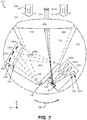
- Figure 2 is a cross-section view of an example LIDAR device 200.
- the LIDAR device 200 includes a housing 210 that houses a transmit block 220, a receive block 230, a shared space 240, and a lens 250.
- Figure 2 shows an x-y-z axis, in which the z-axis is in a substantially vertical direction and the x-axis and y-axis define a substantially horizontal plane.
- the structure, function, and operation of various components included in the LIDAR device 200 are similar to corresponding components included in the LIDAR device 100 described in Figure 1 .
- the housing 210, the transmit block 220, the receive block 230, the shared space 240, and the lens 250 are similar, respectively, to the housing 110, the transmit block 120, the receive block 130, and the shared space 140 described in Figure 1 .
- the transmit block 220 includes a plurality of light sources 222a-c arranged along a curved focal surface 228 defined by the lens 250.
- the plurality of light sources 222a-c can be configured to emit, respectively, the plurality of light beams 202a-c having wavelengths within a wavelength range.
- the plurality of light sources 222a-c may comprise laser diodes that emit the plurality of light beams 202a-c having the wavelengths within the wavelength range.
- the plurality of light beams 202a-c are reflected by mirror 224 through an exit aperture 226 into the shared space 240 and towards the lens 250.
- the structure, function, and operation of the plurality of light sources 222a-c, the mirror 224, and the exit aperture 226 can be similar, respectively, to the plurality of light sources 122, the mirror 124, and the exit aperture 226 discussed in the description of the LIDAR device 100 of Figure 1 .
- Figure 2 shows that the curved focal surface 228 is curved in the x-y plane (horizontal plane), additionally or alternatively, the plurality of light sources 222a-c may be arranged along a focal surface that is curved in a vertical plane.
- the curved focal surface 228 can have a curvature in a vertical plane, and the plurality of light sources 222a-c can include additional light sources arranged vertically along the curved focal surface 228 and configured to emit light beams directed at the mirror 224 and reflected through the exit aperture 226.
- the plurality of light beams 202a-c may converge towards the exit aperture 226.
- the exit aperture 226 may be minimally sized while being capable of accommodating vertical and horizontal extents of the plurality of light beams 202a-c.
- the curved focal surface 228 can be defined by the lens 250.
- the curved focal surface 228 may correspond to a focal surface of the lens 250 due to shape and composition of the lens 250.
- the plurality of light sources 222a-c can be arranged along the focal surface defined by the lens 250 at the transmit block.
- the plurality of light beams 202a-c propagate in a transmit path that extends through the transmit block 220, the exit aperture 226, and the shared space 240 towards the lens 250.
- the lens 250 collimates the plurality of light beams 202a-c to provide collimated light beams 204a-c into an environment of the LIDAR device 200.
- the collimated light beams 204a-c correspond, respectively, to the plurality of light beams 202a-c.
- the collimated light beams 204a-c reflect off one or more objects in the environment of the LIDAR device 200 as reflected light 206.
- the reflected light 206 may be focused by the lens 250 into the shared space 240 as focused light 208 traveling along a receive path that extends through the shared space 240 onto the receive block 230.
- the focused light 208 may be reflected by the reflective surface 242 as focused light 208a-c propagating towards the receive block 230.
- the lens 250 may be capable of both collimating the plurality of light beams 202a-c and focusing the reflected light 206 along the receive path 208 towards the receive block 230 due to shape and composition of the lens 250.
- the lens 250 can have an aspheric surface 252 facing outside of the housing 210 and a toroidal surface 254 facing the shared space 240.
- the exit aperture 226 is included in a wall 244 that separates the transmit block 220 from the shared space 240.
- the wall 244 can be formed from a transparent material (e.g., glass) that is coated with a reflective material 242.
- the exit aperture 226 may correspond to the portion of the wall 244 that is not coated by the reflective material 242. Additionally or alternatively, the exit aperture 226 may comprise a hole or cut-away in the wall 244.
- the focused light 208 is reflected by the reflective surface 242 and directed towards an entrance aperture 234 of the receive block 230.
- the entrance aperture 234 may comprise a filtering window configured to allow wavelengths in the wavelength range of the plurality of light beams 202a-c emitted by the plurality of light sources 222a-c and attenuate other wavelengths.
- the focused light 208a-c reflected by the reflective surface 242 from the focused light 208 propagates, respectively, onto a plurality of detectors 232a-c.
- the structure, function, and operation of the entrance aperture 234 and the plurality of detectors 232a-c is similar, respectively, to the entrance aperture 134 and the plurality of detectors 132 included in the LIDAR device 100 described in Figure 1 .
- the plurality of detectors 232a-c can be arranged along a curved focal surface 238 of the receive block 230.
- Figure 2 shows that the curved focal surface 238 is curved along the x-y plane (horizontal plane), additionally or alternatively, the curved focal surface 238 can be curved in a vertical plane.
- the curvature of the focal surface 238 is also defined by the lens 250.
- the curved focal surface 238 may correspond to a focal surface of the light projected by the lens 250 along the receive path at the receive block 230.
- Each of the focused light 208a-c corresponds, respectively, to the emitted light beams 202a-c and is directed onto, respectively, the plurality of detectors 232a-c.
- the detector 232a is configured and arranged to received focused light 208a that corresponds to collimated light beam 204a reflected of the one or more objects in the environment of the LIDAR device 200.
- the collimated light beam 204a corresponds to the light beam 202a emitted by the light source 222a.
- the detector 232a receives light that was emitted by the light source 222a
- the detector 232b receives light that was emitted by the light source 222b
- the detector 232c receives light that was emitted by the light source 222c.
- At least one aspect of the one or more object in the environment of the LIDAR device 200 may be determined. For example, by comparing a time when the plurality of light beams 202a-c were emitted by the plurality of light sources 222a-c and a time when the plurality of detectors 232a-c received the focused light 208a-c, a distance between the LIDAR device 200 and the one or more object in the environment of the LIDAR device 200 may be determined. In some examples, other aspects such as shape, color, material, etc. may also be determined.
- the LIDAR device 200 may be rotated about an axis to determine a three-dimensional map of the surroundings of the LIDAR device 200.
- the LIDAR device 200 may be rotated about a substantially vertical axis as illustrated by arrow 290.
- the LIDAR device 200 may be rotated counter clock-wise about the axis as illustrated by the arrow 290, additionally or alternatively, the LIDAR device 200 may be rotated in the clockwise direction.
- the LIDAR device 200 may be rotated 360 degrees about the axis.
- the LIDAR device 200 may be rotated back and forth along a portion of the 360 degree view of the LIDAR device 200.
- the LIDAR device 200 may be mounted on a platform that wobbles back and forth about the axis without making a complete rotation.
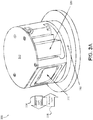
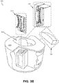
- Figure 3A is a perspective view of an example LIDAR device 300 fitted with various components, in accordance with at least some embodiments described herein.
- Figure 3B is a perspective view of the example LIDAR device 300 shown in Figure 3A with the various components removed to illustrate interior space of the housing 310.
- the structure, function, and operation of the LIDAR device 300 is similar to the LIDAR devices 100 and 200 described, respectively, in Figures 1 and 2 .
- the LIDAR device 300 includes a housing 310 that houses a transmit block 320, a receive block 330, and a lens 350 that are similar, respectively, to the housing 110, the transmit block 120, the receive block 130, and the lens 150 described in Figure 1 .
- collimated light beams 304 propagate from the lens 350 toward an environment of the LIDAR device 300 and reflect of one or more objects in the environment as reflected light 306, similarly to the collimated light beams 104 and reflected light 106 described in Figure 1 .
- the LIDAR device 300 can be mounted on a mounting structure 360 and rotated about an axis to provide a 360 degree view of the environment surrounding the LIDAR device 300.
- the mounting structure 360 may comprise a movable platform that may tilt in one or more directions to change the axis of rotation of the LIDAR device 300.
- the various components of the LIDAR device 300 can be removably mounted to the housing 310.
- the transmit block 320 may comprise one or more printed circuit boards (PCBs) that are fitted in the portion of the housing 310 where the transmit block 320 can be mounted.
- the receive block 330 may comprise a plurality of detectors 332 mounted to a flexible substrate and can be removably mounted to the housing 310 as a block that includes the plurality of detectors.
- the lens 350 can be mounted to another side of the housing 310.
- a plurality of light beams 302 can be transmitted by the transmit block 320 into the shared space 340 and towards the lens 350 to be collimated into the collimated light beams 304.
- the received light 306 can be focused by the lens 350 and directed through the shared space 340 onto the receive block 330.
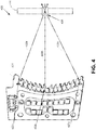
- FIG 4 illustrates an example transmit block 420, in accordance with at least some embodiments described herein.
- Transmit block 420 can correspond to the transmit blocks 120, 220, and 320 described in Figures 1-3 .
- the transmit block 420 includes a plurality of light sources 422a-c similar to the plurality of light sources 222a-c included in the transmit block 220 of Figure 2 .
- the light sources 422a-c are arranged along a focal surface 428, which is curved in a vertical plane.
- the light sources 422a-c are configured to emit a plurality of light beams 402a-c that converge and propagate through an exit aperture 426 in a wall 444.
- the plurality of light sources 422a-c can be arranged along a focal surface 428 that is curved in a vertical plane, additionally or alternatively, the plurality of light sources 422a-c can be arranged along a focal surface that is curved in a horizontal plane or a focal surface that is curved both vertically and horizontally.
- the plurality of light sources 422a-c can be arranged in a curved three dimensional grid pattern.
- the transmit block 420 may comprise a plurality of printed circuit board (PCB) vertically mounted such that a column of light sources such as the plurality of light sources 422a-c are along the vertical axis of each PCB and each of the plurality of PCBs can be arranged adjacent to other vertically mounted PCBs along a horizontally curved plane to provide the three dimensional grid pattern.
- PCB printed circuit board
- the light beams 402a-c converge towards the exit aperture 426 which allows the size of the exit aperture 426 to be minimized while accommodating vertical and horizontal extents of the light beams 402a-c similarly to the exit aperture 226 described in Figure 2 .
- a light source 500 is made up of a laser diode 502 and a cylindrical lens 504.
- laser diode 502 has an aperture 506 with a shorter dimension corresponding to a fast axis 508 and a longer dimension corresponding to a slow axis 510.
- Figures 5B and 5C show an uncollimated laser beam 512 being emitted from laser diode 502.
- Laser beam 512 diverges in two directions, one direction defined by fast axis 508 and another, generally orthogonal direction defined by slow axis 510.
- Figure 5B shows the divergence of laser beam 512 along fast axis 508, whereas
- Figure 5C shows the divergence of laser beam 512 along slow axis 510.
- Laser beam 512 diverges more quickly along fast axis 508 than along slow axis 510.
- laser diode 502 is an Osram SPL DL90_3 nanostack pulsed laser diode that emits pulses of light with a range of wavelengths from about 896 nm to about 910 nm (a nominal wavelength of 905 nm).
- the aperture has a shorter dimension of about 10 microns, corresponding to its fast axis, and a longer dimension of about 200 microns, corresponding to its slow axis.
- the divergence of the laser beam in this specific example is about 25 degrees along the fast axis and about 11 degrees along the slow axis. It is to be understood that this specific example is illustrative only.
- Laser diode 502 could have a different configuration, different aperture sizes, different beam divergences, and/or emit different wavelengths.
- cylindrical lens 504 may be positioned in front of aperture 506 with its cylinder axis 514 generally parallel to slow axis 510 and perpendicular to fast axis 508.
- cylindrical lens 504 can pre-collimate laser beam 512 along fast axis 508, resulting in partially collimated laser beam 516.
- this pre-collimation may reduce the divergence along fast axis 508 to about one degree or less. Nonetheless, laser beam 516 is only partially collimated because the divergence along slow axis 510 may be largely unchanged by cylindrical lens 504.
- partially collimated laser beam 516 provided by cylindrical lens 504 may have a higher divergence along slow axis 510 than along fast axis 508. Further, the divergences along slow axis 510 in uncollimated laser beam 512 and in partially collimated laser beam 516 may be substantially equal.
- cylindrical lens 504 is a microrod lens with a diameter of about 600 microns that is placed about 250 microns in front of aperture 506.
- the material of the microrod lens could be, for example, fused silica or a borosilicate crown glass, such as Schott BK7.
- the microrod lens could be a molded plastic cylinder or acylinder.
- Cylindrical lens 504 could also be used to provide magnification along fast axis 508. For example, if the dimensions of aperture 506 are 10 microns by 200 microns, as previously described, and cylindrical lens 504 is a microrod lens as described above, then cylindrical lens 504 may magnify the shorter dimension (corresponding to fast axis 508) by about 20 times.
- This magnification effectively stretches out the shorter dimension of aperture 506 to about the same as the longer dimension.
- the focused spot could have a substantially square shape instead of the rectangular slit shape of aperture 506.
- Figure 6A illustrates an example receive block 630, in accordance with at least some embodiments described herein.
- Figure 6B illustrates a side view of three detectors 632a-c included in the receive block 630 of Figure 6A .
- Receive block 630 can correspond to the receive blocks 130, 230, and 330 described in Figures 1-3 .
- the receive block 630 includes a plurality of detectors 632a-c arranged along a curved surface 638 defined by a lens 650 similarly to the receive block 230, the detectors 232 and the curved plane 238 described in Figure 2 .
- Focused light 608a-c from lens 650 propagates along a receive path that includes a reflective surface 642 onto the detectors 632a-c similar, respectively, to the focused light 208a-c, the lens 250, the reflective surface 242, and the detectors 232a-c described in Figure 2 .
- the receive block 630 comprises a flexible substrate 680 on which the plurality of detectors 632a-c are arranged along the curved surface 638.
- the flexible substrate 680 conforms to the curved surface 638 by being mounted to a receive block housing 690 having the curved surface 638.
- the curved surface 638 includes the arrangement of the detectors 632a-c curved along a vertical and horizontal axis of the receive block 630.
- Figures 7A and 7B illustrate an example lens 750 with an aspheric surface 752 and a toroidal surface 754, in accordance with at least some embodiments described herein.
- Figure 7B illustrates a cross-section view of the example lens 750 shown in Figure 7A .
- the lens 750 can correspond to lens 150, 250, and 350 included in Figures 1-3 .
- the lens 750 can be configured to both collimate light incident on the toroidal surface 754 from a light source into collimated light propagating out of the aspheric surface 752, and focus reflected light entering from the aspheric surface 752 onto a detector.
- the structure of the lens 750 including the aspheric surface 752 and the toroidal surface 754 allows the lens 750 to perform both functions of collimating and focusing described in the example above.
- the lens 750 defines a focal surface of the light propagating through the lens 750 due to the aspheric surface 752 and the toroidal surface 754.
- the light sources providing the light entering the toroidal surface 754 can be arranged along the defined focal surface, and the detectors receiving the light focused from the light entering the aspheric surface 752 can also be arranged along the defined focal surface.
- the lens 750 that performs both of these functions (collimating transmitted light and focusing received light), instead of a transmit lens for collimating and a receive lens for focusing, advantages with respect to size, cost, and/or complexity can be provided.
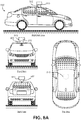
- Figure 8A illustrates an example LIDAR device 810 mounted on a vehicle 800, in accordance with at least some embodiments described herein.
- Figure 8A shows a Right Side View, Front View, Back View, and Top View of the vehicle 800.
- vehicle 800 is illustrated in Figure 8 as a car, other examples are possible.
- the vehicle 800 could represent a truck, a van, a semi-trailer truck, a motorcycle, a golf cart, an off-road vehicle, or a farm vehicle, among other examples.
- the LIDAR device 810 shown in Figure 8A is similar to the example LIDAR devices 100, 200, and 300 shown in Figures 1-3 .
- the LIDAR device 810 can be configured to rotate about an axis and determine a three-dimensional map of a surrounding environment of the LIDAR device 810.
- the LIDAR device 810 can be mounted on a platform 802.
- the platform 802 may comprise a movable mount that allows the vehicle 800 to control the axis of rotation of the LIDAR device 810.
- the LIDAR device 810 is shown to be mounted in a particular location on the vehicle 800, in some examples, the LIDAR device 810 may be mounted elsewhere on the vehicle 800. For example, the LIDAR device 810 may be mounted anywhere on top of the vehicle 800, on a side of the vehicle 800, under the vehicle 800, on a hood of the vehicle 800, and/or on a trunk of the vehicle 800.
- the LIDAR device 810 includes a lens 812 through which collimated light is transmitted from the LIDAR device 810 to the surrounding environment of the LIDAR device 810, similarly to the lens 150, 250, and 350 described in Figures 1-3 .
- the lens 812 can also be configured to receive reflected light from the surrounding environment of the LIDAR device 810 that were reflected off one or more objects in the surrounding environment.
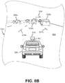
- Figure 8B illustrates a scenario where the LIDAR device 810 shown in Figure 8A and scanning an environment 830 that includes one or more objects, in accordance with at least some embodiments described herein.
- vehicle 800 can be traveling on a road 822 in the environment 830.
- the LIDAR device 810 may be able to determine aspects of objects in the surrounding environment 830, such as lane lines 824a-b, other vehicles 826a-c, and/or street sign 828.
- the LIDAR device 810 can provide the vehicle 800 with information about the objects in the surrounding environment 830, including distance, shape, color, and/or material type of the objects.
- Figure 9 is a flowchart of a method 900 of operating a LIDAR device, in accordance with at least some embodiments described herein.
- Method 900 shown in Figure 9 presents an embodiment of a method that could be used with the LIDAR devices 100, 200, and 300, for example.
- Method 900 may include one or more operations, functions, or actions as illustrated by one or more of blocks 902-912. Although the blocks are illustrated in a sequential order, these blocks may in some instances be performed in parallel, and/or in a different order than those described herein. Also, the various blocks may be combined into fewer blocks, divided into additional blocks, and/or removed based upon the desired implementation.
- each block may represent a module, a segment, or a portion of a manufacturing or operation process.
- the method 900 includes rotating a housing of a light detection and ranging (LIDAR) device about an axis, wherein the housing has an interior space that includes a transmit block, a receive block, and a shared space, wherein the transmit block has an exit aperture, and wherein the receive block has an entrance aperture.
- LIDAR light detection and ranging
- the method 900 includes emitting, by a plurality of light sources in the transmit block, a plurality of light beams that enter the shared space via a transmit path, the light beams comprising light having wavelengths in a wavelength range.
- the method 900 includes receiving the light beams at a lens mounted to the housing along the transmit path.
- the method 900 includes collimating, by the lens, the light beams for transmission into an environment of the LIDAR device.
- the method 900 includes focusing, by the lens, the collected light onto a plurality of detectors in the receive block via a receive path that extends through the shared space and the entrance aperture of the receive block.
- the method 900 includes detecting, by the plurality of detectors in the receive block, light from the focused light having wavelengths in the wavelength range.
- a LIDAR device such as the LIDAR device 200 can be rotated about an axis (block 902).
- a transmit block such as the transmit block 220, can include a plurality of light sources that emit light beams having wavelengths in a wavelength range, through an exit aperture and a shared space to a lens (block 904).
- the light beams can be received by the lens (block 906) and collimated for transmission to an environment of the LIDAR device (block 908).
- the collimated light may then reflect off one or more objects in the environment of the LIDAR device and return as reflected light collected by the lens.
- the lens may then focus the collected light onto a plurality of detectors in the receive block via a receive path that extends through the shared space and an entrance aperture of the receive block (block 910).
- the plurality of detectors in the receive block may then detect light from the focused light having wavelengths in the wavelength range of the emitted light beams from the light sources (block 912).
- devices and operation methods described include a LIDAR device rotated about an axis and configured to transmit collimated light and focus reflected light.
- the collimation and focusing can be performed by a shared lens.
- a shared lens that performs both of these functions, instead of a transmit lens for collimating and a receive lens for focusing, advantages with respect to size, cost, and/or complexity can be provided.
- the shared lens can define a curved focal surface.
- the light sources emitting light through the shared lens and the detectors receiving light focused by the shared lens can be arranged along the curved focal surface defined by the shared lens.
Landscapes
- Engineering & Computer Science (AREA)
- Physics & Mathematics (AREA)
- Computer Networks & Wireless Communication (AREA)
- General Physics & Mathematics (AREA)
- Radar, Positioning & Navigation (AREA)
- Remote Sensing (AREA)
- Electromagnetism (AREA)
- Optical Radar Systems And Details Thereof (AREA)
- Mechanical Optical Scanning Systems (AREA)
- Measurement Of Optical Distance (AREA)
Priority Applications (1)
| Application Number | Priority Date | Filing Date | Title |
|---|---|---|---|
| EP20204733.8A EP3798672B1 (en) | 2013-08-20 | 2014-07-23 | Devices and methods for a rotating lidar platform with a shared transmit/receive path |
Applications Claiming Priority (2)
| Application Number | Priority Date | Filing Date | Title |
|---|---|---|---|
| US13/971,606 US8836922B1 (en) | 2013-08-20 | 2013-08-20 | Devices and methods for a rotating LIDAR platform with a shared transmit/receive path |
| PCT/US2014/047864 WO2015026471A1 (en) | 2013-08-20 | 2014-07-23 | Devices and methods for a rotating lidar platform with a shared transmit/receive path |
Related Child Applications (1)
| Application Number | Title | Priority Date | Filing Date |
|---|---|---|---|
| EP20204733.8A Division EP3798672B1 (en) | 2013-08-20 | 2014-07-23 | Devices and methods for a rotating lidar platform with a shared transmit/receive path |
Publications (3)
| Publication Number | Publication Date |
|---|---|
| EP3036562A1 EP3036562A1 (en) | 2016-06-29 |
| EP3036562A4 EP3036562A4 (en) | 2017-04-12 |
| EP3036562B1 true EP3036562B1 (en) | 2020-11-25 |
Family
ID=51493404
Family Applications (2)
| Application Number | Title | Priority Date | Filing Date |
|---|---|---|---|
| EP14838560.2A Active EP3036562B1 (en) | 2013-08-20 | 2014-07-23 | Devices and methods for a rotating lidar platform with a shared transmit/receive path |
| EP20204733.8A Active EP3798672B1 (en) | 2013-08-20 | 2014-07-23 | Devices and methods for a rotating lidar platform with a shared transmit/receive path |
Family Applications After (1)
| Application Number | Title | Priority Date | Filing Date |
|---|---|---|---|
| EP20204733.8A Active EP3798672B1 (en) | 2013-08-20 | 2014-07-23 | Devices and methods for a rotating lidar platform with a shared transmit/receive path |
Country Status (6)
| Country | Link |
|---|---|
| US (5) | US8836922B1 (enExample) |
| EP (2) | EP3036562B1 (enExample) |
| JP (2) | JP6249577B2 (enExample) |
| KR (3) | KR101956045B1 (enExample) |
| CN (2) | CN111487600A (enExample) |
| WO (1) | WO2015026471A1 (enExample) |
Families Citing this family (296)
| Publication number | Priority date | Publication date | Assignee | Title |
|---|---|---|---|---|
| USRE46672E1 (en) | 2006-07-13 | 2018-01-16 | Velodyne Lidar, Inc. | High definition LiDAR system |
| US9414458B2 (en) | 2007-05-24 | 2016-08-09 | Federal Law Enforcement Development Services, Inc. | LED light control assembly and system |
| US11265082B2 (en) | 2007-05-24 | 2022-03-01 | Federal Law Enforcement Development Services, Inc. | LED light control assembly and system |
| US9455783B2 (en) | 2013-05-06 | 2016-09-27 | Federal Law Enforcement Development Services, Inc. | Network security and variable pulse wave form with continuous communication |
| US9100124B2 (en) | 2007-05-24 | 2015-08-04 | Federal Law Enforcement Development Services, Inc. | LED Light Fixture |
| WO2008148022A2 (en) | 2007-05-24 | 2008-12-04 | Federal Law Enforcement Development Services, Inc. | Building illumination apparatus with integrated communications, security and energy management |
| US8890773B1 (en) | 2009-04-01 | 2014-11-18 | Federal Law Enforcement Development Services, Inc. | Visible light transceiver glasses |
| DE102011119707A1 (de) * | 2011-11-29 | 2013-05-29 | Valeo Schalter Und Sensoren Gmbh | Optische Messvorrichtung |
| US9063549B1 (en) * | 2013-03-06 | 2015-06-23 | Google Inc. | Light detection and ranging device with oscillating mirror driven by magnetically interactive coil |
| US10132928B2 (en) | 2013-05-09 | 2018-11-20 | Quanergy Systems, Inc. | Solid state optical phased array lidar and method of using same |
| US10126412B2 (en) * | 2013-08-19 | 2018-11-13 | Quanergy Systems, Inc. | Optical phased array lidar system and method of using same |
| US8836922B1 (en) | 2013-08-20 | 2014-09-16 | Google Inc. | Devices and methods for a rotating LIDAR platform with a shared transmit/receive path |
| US9368936B1 (en) | 2013-09-30 | 2016-06-14 | Google Inc. | Laser diode firing system |
| US10203399B2 (en) | 2013-11-12 | 2019-02-12 | Big Sky Financial Corporation | Methods and apparatus for array based LiDAR systems with reduced interference |
| US20150198941A1 (en) | 2014-01-15 | 2015-07-16 | John C. Pederson | Cyber Life Electronic Networking and Commerce Operating Exchange |
| US9360554B2 (en) * | 2014-04-11 | 2016-06-07 | Facet Technology Corp. | Methods and apparatus for object detection and identification in a multiple detector lidar array |
| US9753351B2 (en) | 2014-06-30 | 2017-09-05 | Quanergy Systems, Inc. | Planar beam forming and steering optical phased array chip and method of using same |
| US9869753B2 (en) | 2014-08-15 | 2018-01-16 | Quanergy Systems, Inc. | Three-dimensional-mapping two-dimensional-scanning lidar based on one-dimensional-steering optical phased arrays and method of using same |
| US10036803B2 (en) * | 2014-10-20 | 2018-07-31 | Quanergy Systems, Inc. | Three-dimensional lidar sensor based on two-dimensional scanning of one-dimensional optical emitter and method of using same |
| US10036801B2 (en) | 2015-03-05 | 2018-07-31 | Big Sky Financial Corporation | Methods and apparatus for increased precision and improved range in a multiple detector LiDAR array |
| US10088557B2 (en) | 2015-03-20 | 2018-10-02 | MSOTEK Co., Ltd | LIDAR apparatus |
| US9625582B2 (en) | 2015-03-25 | 2017-04-18 | Google Inc. | Vehicle with multiple light detection and ranging devices (LIDARs) |
| US9880263B2 (en) * | 2015-04-06 | 2018-01-30 | Waymo Llc | Long range steerable LIDAR system |
| CN106291580B (zh) | 2015-06-12 | 2019-08-23 | 上海珏芯光电科技有限公司 | 激光雷达成像系统 |
| DE102015110767A1 (de) * | 2015-07-03 | 2017-01-05 | Valeo Schalter Und Sensoren Gmbh | Detektoreinheit für eine optische Sensorvorrichtung |
| KR102422783B1 (ko) * | 2015-08-03 | 2022-07-19 | 엘지이노텍 주식회사 | 광파 탐지 및 거리 측정 장치 |
| US20170048953A1 (en) | 2015-08-11 | 2017-02-16 | Federal Law Enforcement Development Services, Inc. | Programmable switch and system |
| US10063849B2 (en) | 2015-09-24 | 2018-08-28 | Ouster, Inc. | Optical system for collecting distance information within a field |
| US9992477B2 (en) | 2015-09-24 | 2018-06-05 | Ouster, Inc. | Optical system for collecting distance information within a field |
| US10557939B2 (en) | 2015-10-19 | 2020-02-11 | Luminar Technologies, Inc. | Lidar system with improved signal-to-noise ratio in the presence of solar background noise |
| US9720415B2 (en) | 2015-11-04 | 2017-08-01 | Zoox, Inc. | Sensor-based object-detection optimization for autonomous vehicles |
| US9841495B2 (en) | 2015-11-05 | 2017-12-12 | Luminar Technologies, Inc. | Lidar system with improved scanning speed for high-resolution depth mapping |
| JP6852085B2 (ja) | 2015-11-30 | 2021-03-31 | ルミナー テクノロジーズ インコーポレイテッド | 分布型レーザー及び複数のセンサー・ヘッドを備える光検出及び測距システム、並びに、光検出及び測距システムのパルス・レーザー |
| KR101909327B1 (ko) | 2015-12-11 | 2018-10-17 | 전자부품연구원 | 송수광 렌즈를 공유하는 광학계 구조를 가지는 스캐닝 라이다 |
| KR20170071181A (ko) * | 2015-12-15 | 2017-06-23 | 한화테크윈 주식회사 | 회전체 |
| DE102015121840A1 (de) * | 2015-12-15 | 2017-06-22 | Sick Ag | Optoelektronischer Sensor und Verfahren zur Erfassung eines Objekts |
| DE102015121839A1 (de) * | 2015-12-15 | 2017-06-22 | Sick Ag | Optoelektronischer Sensor und Verfahren zur Erfassung eines Objekts |
| JPWO2017110574A1 (ja) * | 2015-12-24 | 2018-10-11 | コニカミノルタ株式会社 | 投受光ユニット及びレーダー |
| WO2017110573A1 (ja) * | 2015-12-24 | 2017-06-29 | コニカミノルタ株式会社 | 投受光ユニット及びレーダー |
| KR102204980B1 (ko) * | 2015-12-29 | 2021-01-19 | 한국전자기술연구원 | 스캐닝 수직 영역이 가변되는 스캐닝 라이다 |
| US9989406B2 (en) * | 2016-01-29 | 2018-06-05 | Ouster, Inc. | Systems and methods for calibrating an optical distance sensor |
| CA3012691C (en) * | 2016-01-31 | 2023-02-28 | Velodyne Lidar, Inc. | Lidar based 3-d imaging with far-field illumination overlap |
| US10627490B2 (en) | 2016-01-31 | 2020-04-21 | Velodyne Lidar, Inc. | Multiple pulse, LIDAR based 3-D imaging |
| US12399279B1 (en) | 2016-02-15 | 2025-08-26 | Red Creamery Llc | Enhanced hybrid LIDAR with high-speed scanning |
| US12123950B2 (en) | 2016-02-15 | 2024-10-22 | Red Creamery, LLC | Hybrid LADAR with co-planar scanning and imaging field-of-view |
| US12399278B1 (en) | 2016-02-15 | 2025-08-26 | Red Creamery Llc | Hybrid LIDAR with optically enhanced scanned laser |
| US11556000B1 (en) | 2019-08-22 | 2023-01-17 | Red Creamery Llc | Distally-actuated scanning mirror |
| WO2017164989A1 (en) | 2016-03-19 | 2017-09-28 | Velodyne Lidar, Inc. | Integrated illumination and detection for lidar based 3-d imaging |
| EP3226031A1 (en) * | 2016-03-29 | 2017-10-04 | Leica Geosystems AG | Laser scanner |
| US10761195B2 (en) | 2016-04-22 | 2020-09-01 | OPSYS Tech Ltd. | Multi-wavelength LIDAR system |
| US10838062B2 (en) | 2016-05-24 | 2020-11-17 | Veoneer Us, Inc. | Direct detection LiDAR system and method with pulse amplitude modulation (AM) transmitter and quadrature receiver |
| US10416292B2 (en) | 2016-05-24 | 2019-09-17 | Veoneer Us, Inc. | Direct detection LiDAR system and method with frequency modulation (FM) transmitter and quadrature receiver |
| KR102235710B1 (ko) * | 2016-05-31 | 2021-04-02 | 한국전자기술연구원 | 송수광 단일렌즈 광학계 구조를 가지는 스캐닝 라이다 |
| CA3024510C (en) | 2016-06-01 | 2022-10-04 | Velodyne Lidar, Inc. | Multiple pixel scanning lidar |
| US10212785B2 (en) | 2016-06-13 | 2019-02-19 | Google Llc | Staggered array of individually addressable light-emitting elements for sweeping out an angular range |
| US9909862B2 (en) | 2016-06-13 | 2018-03-06 | Google Llc | Curved array of light-emitting elements for sweeping out an angular range |
| WO2018021800A1 (ko) | 2016-07-25 | 2018-02-01 | 엘지이노텍 주식회사 | 수광 장치 및 라이다 |
| KR102209500B1 (ko) | 2016-08-02 | 2021-02-01 | 연용현 | 라이다 장치 |
| CN113325393B (zh) | 2016-08-24 | 2024-12-06 | 奥斯特公司 | 用于收集场内的距离信息的光学系统 |
| US10066986B2 (en) * | 2016-08-31 | 2018-09-04 | GM Global Technology Operations LLC | Light emitting sensor having a plurality of secondary lenses of a moveable control structure for controlling the passage of light between a plurality of light emitters and a primary lens |
| KR102547651B1 (ko) * | 2016-09-20 | 2023-06-26 | 이노비즈 테크놀로지스 엘티디 | Lidar 시스템 및 방법 |
| KR102210101B1 (ko) * | 2016-09-22 | 2021-02-02 | 한국전자기술연구원 | 광학계 모듈 및 그를 갖는 스캐닝 라이다 |
| RU2718483C2 (ru) * | 2016-09-23 | 2020-04-08 | Общество с ограниченной ответственностью "Гардиан Стекло Сервиз" | Система и/или способ распознавания покрытия для стекла |
| FR3056524B1 (fr) * | 2016-09-28 | 2018-10-12 | Valeo Systemes D'essuyage | Systeme de detection pour vehicule automobile |
| EP3519850B1 (en) * | 2016-09-30 | 2024-10-30 | Magic Leap, Inc. | Projector with spatial light modulation |
| US10502830B2 (en) * | 2016-10-13 | 2019-12-10 | Waymo Llc | Limitation of noise on light detectors using an aperture |
| US10379540B2 (en) * | 2016-10-17 | 2019-08-13 | Waymo Llc | Light detection and ranging (LIDAR) device having multiple receivers |
| DE102016220468B4 (de) | 2016-10-19 | 2025-12-11 | Robert Bosch Gmbh | Lidar-Sensor zur Erfassung eines Objektes |
| US10845470B2 (en) | 2016-11-16 | 2020-11-24 | Waymo Llc | Methods and systems for protecting a light detection and ranging (LIDAR) device |
| USD871412S1 (en) * | 2016-11-21 | 2019-12-31 | Datalogic Ip Tech S.R.L. | Optical scanner |
| US10605984B2 (en) * | 2016-12-01 | 2020-03-31 | Waymo Llc | Array of waveguide diffusers for light detection using an aperture |
| US10502618B2 (en) | 2016-12-03 | 2019-12-10 | Waymo Llc | Waveguide diffuser for light detection using an aperture |
| DE102016224509A1 (de) | 2016-12-08 | 2018-06-14 | Zf Friedrichshafen Ag | Empfängeranordnung und Verfahren zum Empfang wenigstens eines Lichtimpulses und zur Ausgabe eines Empfangssignals |
| US10001551B1 (en) * | 2016-12-19 | 2018-06-19 | Waymo Llc | Mirror assembly |
| US10955530B2 (en) * | 2016-12-23 | 2021-03-23 | Cepton Technologies, Inc. | Systems for vibration cancellation in a lidar system |
| TW201823673A (zh) * | 2016-12-28 | 2018-07-01 | 鴻海精密工業股份有限公司 | 鐳射測距裝置 |
| US10591740B2 (en) | 2016-12-30 | 2020-03-17 | Panosense Inc. | Lens assembly for a LIDAR system |
| US10359507B2 (en) | 2016-12-30 | 2019-07-23 | Panosense Inc. | Lidar sensor assembly calibration based on reference surface |
| US10742088B2 (en) | 2016-12-30 | 2020-08-11 | Panosense Inc. | Support assembly for rotating body |
| US10122416B2 (en) | 2016-12-30 | 2018-11-06 | Panosense Inc. | Interface for transferring power and data between a non-rotating body and a rotating body |
| US11255951B1 (en) | 2016-12-30 | 2022-02-22 | Zoox, Inc. | Aligning optical components in LIDAR systems |
| US10830878B2 (en) * | 2016-12-30 | 2020-11-10 | Panosense Inc. | LIDAR system |
| US10109183B1 (en) | 2016-12-30 | 2018-10-23 | Panosense Inc. | Interface for transferring data between a non-rotating body and a rotating body |
| US10048358B2 (en) | 2016-12-30 | 2018-08-14 | Panosense Inc. | Laser power calibration and correction |
| US10942257B2 (en) | 2016-12-31 | 2021-03-09 | Innovusion Ireland Limited | 2D scanning high precision LiDAR using combination of rotating concave mirror and beam steering devices |
| US10520592B2 (en) * | 2016-12-31 | 2019-12-31 | Waymo Llc | Light detection and ranging (LIDAR) device with an off-axis receiver |
| WO2018132632A1 (en) | 2017-01-13 | 2018-07-19 | Diversey, Inc. | Three-dimensional scanning using fixed planar distance sensors |
| DE102017101945A1 (de) * | 2017-02-01 | 2018-08-02 | Osram Opto Semiconductors Gmbh | Messanordnung mit einem optischen Sender und einem optischen Empfänger |
| DE102017202957B4 (de) | 2017-02-23 | 2024-06-27 | Zf Friedrichshafen Ag | Empfängeranordnung, Halbleiterbaustein und Verfahren zum Empfang von Lichtimpulsen und zur Ausgabe eines Empfangssignals |
| US11105925B2 (en) | 2017-03-01 | 2021-08-31 | Ouster, Inc. | Accurate photo detector measurements for LIDAR |
| JP7134988B2 (ja) * | 2017-03-01 | 2022-09-12 | アウスター インコーポレイテッド | ライダーのための正確な光検出器測定 |
| US10338594B2 (en) * | 2017-03-13 | 2019-07-02 | Nio Usa, Inc. | Navigation of autonomous vehicles to enhance safety under one or more fault conditions |
| WO2018169758A1 (en) | 2017-03-13 | 2018-09-20 | OPSYS Tech Ltd. | Eye-safe scanning lidar system |
| US9810775B1 (en) | 2017-03-16 | 2017-11-07 | Luminar Technologies, Inc. | Q-switched laser for LIDAR system |
| US9810786B1 (en) | 2017-03-16 | 2017-11-07 | Luminar Technologies, Inc. | Optical parametric oscillator for lidar system |
| US9905992B1 (en) | 2017-03-16 | 2018-02-27 | Luminar Technologies, Inc. | Self-Raman laser for lidar system |
| US10365351B2 (en) * | 2017-03-17 | 2019-07-30 | Waymo Llc | Variable beam spacing, timing, and power for vehicle sensors |
| US10330780B2 (en) * | 2017-03-20 | 2019-06-25 | Velodyne Lidar, Inc. | LIDAR based 3-D imaging with structured light and integrated illumination and detection |
| US9869754B1 (en) * | 2017-03-22 | 2018-01-16 | Luminar Technologies, Inc. | Scan patterns for lidar systems |
| US10732281B2 (en) | 2017-03-28 | 2020-08-04 | Luminar Technologies, Inc. | Lidar detector system having range walk compensation |
| US10061019B1 (en) | 2017-03-28 | 2018-08-28 | Luminar Technologies, Inc. | Diffractive optical element in a lidar system to correct for backscan |
| US10139478B2 (en) | 2017-03-28 | 2018-11-27 | Luminar Technologies, Inc. | Time varying gain in an optical detector operating in a lidar system |
| US10267899B2 (en) | 2017-03-28 | 2019-04-23 | Luminar Technologies, Inc. | Pulse timing based on angle of view |
| US11119198B2 (en) | 2017-03-28 | 2021-09-14 | Luminar, Llc | Increasing operational safety of a lidar system |
| US10209359B2 (en) | 2017-03-28 | 2019-02-19 | Luminar Technologies, Inc. | Adaptive pulse rate in a lidar system |
| US10114111B2 (en) | 2017-03-28 | 2018-10-30 | Luminar Technologies, Inc. | Method for dynamically controlling laser power |
| US10121813B2 (en) | 2017-03-28 | 2018-11-06 | Luminar Technologies, Inc. | Optical detector having a bandpass filter in a lidar system |
| US10007001B1 (en) | 2017-03-28 | 2018-06-26 | Luminar Technologies, Inc. | Active short-wave infrared four-dimensional camera |
| US10254388B2 (en) | 2017-03-28 | 2019-04-09 | Luminar Technologies, Inc. | Dynamically varying laser output in a vehicle in view of weather conditions |
| US10545240B2 (en) | 2017-03-28 | 2020-01-28 | Luminar Technologies, Inc. | LIDAR transmitter and detector system using pulse encoding to reduce range ambiguity |
| US10663595B2 (en) | 2017-03-29 | 2020-05-26 | Luminar Technologies, Inc. | Synchronized multiple sensor head system for a vehicle |
| US11002853B2 (en) | 2017-03-29 | 2021-05-11 | Luminar, Llc | Ultrasonic vibrations on a window in a lidar system |
| US10088559B1 (en) | 2017-03-29 | 2018-10-02 | Luminar Technologies, Inc. | Controlling pulse timing to compensate for motor dynamics |
| WO2018183715A1 (en) | 2017-03-29 | 2018-10-04 | Luminar Technologies, Inc. | Method for controlling peak and average power through laser receiver |
| US10976417B2 (en) | 2017-03-29 | 2021-04-13 | Luminar Holdco, Llc | Using detectors with different gains in a lidar system |
| US10983213B2 (en) | 2017-03-29 | 2021-04-20 | Luminar Holdco, Llc | Non-uniform separation of detector array elements in a lidar system |
| US10969488B2 (en) | 2017-03-29 | 2021-04-06 | Luminar Holdco, Llc | Dynamically scanning a field of regard using a limited number of output beams |
| US10641874B2 (en) | 2017-03-29 | 2020-05-05 | Luminar Technologies, Inc. | Sizing the field of view of a detector to improve operation of a lidar system |
| US10254762B2 (en) * | 2017-03-29 | 2019-04-09 | Luminar Technologies, Inc. | Compensating for the vibration of the vehicle |
| US10191155B2 (en) | 2017-03-29 | 2019-01-29 | Luminar Technologies, Inc. | Optical resolution in front of a vehicle |
| US10241198B2 (en) | 2017-03-30 | 2019-03-26 | Luminar Technologies, Inc. | Lidar receiver calibration |
| US10295668B2 (en) | 2017-03-30 | 2019-05-21 | Luminar Technologies, Inc. | Reducing the number of false detections in a lidar system |
| US9989629B1 (en) | 2017-03-30 | 2018-06-05 | Luminar Technologies, Inc. | Cross-talk mitigation using wavelength switching |
| US10401481B2 (en) | 2017-03-30 | 2019-09-03 | Luminar Technologies, Inc. | Non-uniform beam power distribution for a laser operating in a vehicle |
| US10684360B2 (en) | 2017-03-30 | 2020-06-16 | Luminar Technologies, Inc. | Protecting detector in a lidar system using off-axis illumination |
| US11022688B2 (en) | 2017-03-31 | 2021-06-01 | Luminar, Llc | Multi-eye lidar system |
| CN110914705B (zh) | 2017-03-31 | 2024-04-26 | 威力登激光雷达美国有限公司 | 用于集成lidar照明功率控制的设备、系统和方法 |
| US20180284246A1 (en) | 2017-03-31 | 2018-10-04 | Luminar Technologies, Inc. | Using Acoustic Signals to Modify Operation of a Lidar System |
| DE102017205504A1 (de) | 2017-03-31 | 2018-10-04 | Robert Bosch Gmbh | Optisches Scansystem |
| US10641876B2 (en) | 2017-04-06 | 2020-05-05 | Quanergy Systems, Inc. | Apparatus and method for mitigating LiDAR interference through pulse coding and frequency shifting |
| US10908282B2 (en) * | 2017-04-07 | 2021-02-02 | General Electric Company | LiDAR system and method |
| US9904375B1 (en) | 2017-04-10 | 2018-02-27 | Uber Technologies, Inc. | LIDAR display systems and methods |
| US10556585B1 (en) | 2017-04-13 | 2020-02-11 | Panosense Inc. | Surface normal determination for LIDAR range samples by detecting probe pulse stretching |
| US10677897B2 (en) | 2017-04-14 | 2020-06-09 | Luminar Technologies, Inc. | Combining lidar and camera data |
| WO2018208843A1 (en) | 2017-05-08 | 2018-11-15 | Velodyne Lidar, Inc. | Lidar data acquisition and control |
| US10423162B2 (en) | 2017-05-08 | 2019-09-24 | Nio Usa, Inc. | Autonomous vehicle logic to identify permissioned parking relative to multiple classes of restricted parking |
| US10649072B2 (en) | 2017-05-10 | 2020-05-12 | Massachusetts Institute Of Technology | LiDAR device based on scanning mirrors array and multi-frequency laser modulation |
| US10564261B2 (en) | 2017-05-11 | 2020-02-18 | Ford Global Technologies, Llc | Autonomous vehicle LIDAR mirror |
| DE102017208047A1 (de) * | 2017-05-12 | 2018-11-15 | Robert Bosch Gmbh | LIDAR-Vorrichtung und Verfahren mit vereinfachter Detektion |
| DE202018006696U1 (de) | 2017-05-15 | 2022-04-01 | Ouster, Inc. | Optischer Bildübertrager mit Helligkeitsverbesserung |
| DE102017208900A1 (de) | 2017-05-26 | 2018-11-29 | Robert Bosch Gmbh | Verfahren und Vorrichtung zum Abtasten eines Raumwinkels |
| US10094916B1 (en) | 2017-06-09 | 2018-10-09 | Waymo Llc | LIDAR optics alignment systems and methods |
| US11294035B2 (en) | 2017-07-11 | 2022-04-05 | Nuro, Inc. | LiDAR system with cylindrical lenses |
| US11061116B2 (en) | 2017-07-13 | 2021-07-13 | Nuro, Inc. | Lidar system with image size compensation mechanism |
| US10710633B2 (en) | 2017-07-14 | 2020-07-14 | Nio Usa, Inc. | Control of complex parking maneuvers and autonomous fuel replenishment of driverless vehicles |
| US10369974B2 (en) | 2017-07-14 | 2019-08-06 | Nio Usa, Inc. | Control and coordination of driverless fuel replenishment for autonomous vehicles |
| CN110914779A (zh) | 2017-07-20 | 2020-03-24 | 纽诺有限公司 | 自主车辆重新定位 |
| US11009868B2 (en) | 2017-07-20 | 2021-05-18 | Nuro, Inc. | Fleet of autonomous vehicles with lane positioning and platooning behaviors |
| US20190033460A1 (en) * | 2017-07-27 | 2019-01-31 | GM Global Technology Operations LLC | Apparatus for increase field of view for lidar detector and illuminator |
| KR102350613B1 (ko) | 2017-07-27 | 2022-01-12 | 주식회사 엠쏘텍 | 비회전형 전방향 라이다 장치 |
| KR102350621B1 (ko) | 2017-07-27 | 2022-01-12 | 주식회사 엠쏘텍 | 라이다 장치 |
| JP6865492B2 (ja) | 2017-07-28 | 2021-04-28 | オプシス テック リミテッド | 小角度発散を伴うvcselアレイlidar送信機 |
| CN110998619B (zh) | 2017-07-28 | 2023-10-24 | 纽诺有限公司 | 用于增销自主载具上的产品的系统与机构 |
| US10698088B2 (en) | 2017-08-01 | 2020-06-30 | Waymo Llc | LIDAR receiver using a waveguide and an aperture |
| DE102017213726A1 (de) | 2017-08-08 | 2019-02-14 | Robert Bosch Gmbh | Sensorvorrichtung zur Detektion eines Objekts |
| DE202017105001U1 (de) * | 2017-08-21 | 2017-09-14 | Jenoptik Advanced Systems Gmbh | LIDAR-Scanner mit MEMS-Spiegel und wenigstens zwei Scanwinkelbereichen |
| DE102017214705A1 (de) * | 2017-08-23 | 2019-02-28 | Robert Bosch Gmbh | Koaxiales LIDAR System mit langgezogener Spiegelöffnung |
| EP3676631A4 (en) * | 2017-09-05 | 2021-04-14 | Waymo LLC | SHARED WAVEGUIDE FOR LIDAR TRANSMITTER AND RECEIVER |
| US10890650B2 (en) | 2017-09-05 | 2021-01-12 | Waymo Llc | LIDAR with co-aligned transmit and receive paths |
| CN107576954A (zh) * | 2017-09-15 | 2018-01-12 | 中科和光(天津)应用激光技术研究所有限公司 | 一种基于激光雷达的发射准直器 |
| US11460550B2 (en) | 2017-09-19 | 2022-10-04 | Veoneer Us, Llc | Direct detection LiDAR system and method with synthetic doppler processing |
| US10838043B2 (en) * | 2017-11-15 | 2020-11-17 | Veoneer Us, Inc. | Scanning LiDAR system and method with spatial filtering for reduction of ambient light |
| US10613200B2 (en) | 2017-09-19 | 2020-04-07 | Veoneer, Inc. | Scanning lidar system and method |
| EP3460519A1 (en) * | 2017-09-25 | 2019-03-27 | Hexagon Technology Center GmbH | Laser scanner |
| EP3460520B1 (en) * | 2017-09-25 | 2023-07-19 | Hexagon Technology Center GmbH | Multi-beam laser scanner |
| US10523880B2 (en) * | 2017-09-28 | 2019-12-31 | Waymo Llc | Synchronized spinning LIDAR and rolling shutter camera system |
| JP6967929B2 (ja) * | 2017-09-28 | 2021-11-17 | シャープ株式会社 | 光センサ及び電子機器 |
| US11194022B2 (en) | 2017-09-29 | 2021-12-07 | Veoneer Us, Inc. | Detection system with reflection member and offset detection array |
| US10684370B2 (en) * | 2017-09-29 | 2020-06-16 | Veoneer Us, Inc. | Multifunction vehicle detection system |
| EP3470872B1 (en) * | 2017-10-11 | 2021-09-08 | Melexis Technologies NV | Sensor device |
| US10003168B1 (en) | 2017-10-18 | 2018-06-19 | Luminar Technologies, Inc. | Fiber laser with free-space components |
| KR102093637B1 (ko) * | 2017-10-20 | 2020-03-27 | 전자부품연구원 | 라이다 장치 및 이를 포함하는 라이다 시스템 |
| US10775485B2 (en) | 2017-10-20 | 2020-09-15 | Korea Electronics Technology Institute | LIDAR device and system comprising the same |
| US10824862B2 (en) | 2017-11-14 | 2020-11-03 | Nuro, Inc. | Three-dimensional object detection for autonomous robotic systems using image proposals |
| KR102634870B1 (ko) | 2017-11-15 | 2024-02-13 | 옵시스 테크 엘티디 | 잡음 적응형 솔리드-스테이트 lidar 시스템 |
| US11585901B2 (en) | 2017-11-15 | 2023-02-21 | Veoneer Us, Llc | Scanning lidar system and method with spatial filtering for reduction of ambient light |
| US10451716B2 (en) | 2017-11-22 | 2019-10-22 | Luminar Technologies, Inc. | Monitoring rotation of a mirror in a lidar system |
| US10310058B1 (en) | 2017-11-22 | 2019-06-04 | Luminar Technologies, Inc. | Concurrent scan of multiple pixels in a lidar system equipped with a polygon mirror |
| US11585902B2 (en) | 2017-11-30 | 2023-02-21 | Cepton Technologies, Inc. | Optical designs using cylindrical lenses for improved resolution in lidar systems |
| US11340336B2 (en) | 2017-12-07 | 2022-05-24 | Ouster, Inc. | Rotating light ranging system with optical communication uplink and downlink channels |
| US11294041B2 (en) | 2017-12-08 | 2022-04-05 | Velodyne Lidar Usa, Inc. | Systems and methods for improving detection of a return signal in a light ranging and detection system |
| US10942244B2 (en) * | 2017-12-12 | 2021-03-09 | Waymo Llc | Systems and methods for LIDARs with adjustable resolution and failsafe operation |
| US11493601B2 (en) | 2017-12-22 | 2022-11-08 | Innovusion, Inc. | High density LIDAR scanning |
| US11340339B2 (en) * | 2017-12-22 | 2022-05-24 | Waymo Llc | Systems and methods for adaptive range coverage using LIDAR |
| CN108061904B (zh) | 2017-12-29 | 2020-12-22 | 华为技术有限公司 | 多线激光雷达 |
| US11022971B2 (en) | 2018-01-16 | 2021-06-01 | Nio Usa, Inc. | Event data recordation to identify and resolve anomalies associated with control of driverless vehicles |
| US11195353B2 (en) | 2018-01-17 | 2021-12-07 | Uatc, Llc | Methods, devices, and systems for communicating autonomous-vehicle status |
| US11592527B2 (en) | 2018-02-16 | 2023-02-28 | Cepton Technologies, Inc. | Systems for incorporating LiDAR sensors in a headlamp module of a vehicle |
| WO2020013890A2 (en) | 2018-02-23 | 2020-01-16 | Innovusion Ireland Limited | Multi-wavelength pulse steering in lidar systems |
| US11988773B2 (en) | 2018-02-23 | 2024-05-21 | Innovusion, Inc. | 2-dimensional steering system for lidar systems |
| EP3775979B1 (en) | 2018-04-01 | 2024-01-17 | Opsys Tech Ltd. | Noise adaptive solid-state lidar system |
| US10324170B1 (en) | 2018-04-05 | 2019-06-18 | Luminar Technologies, Inc. | Multi-beam lidar system with polygon mirror |
| US11029406B2 (en) | 2018-04-06 | 2021-06-08 | Luminar, Llc | Lidar system with AlInAsSb avalanche photodiode |
| JP2019191018A (ja) * | 2018-04-26 | 2019-10-31 | ソニー株式会社 | 測距装置及び測距モジュール |
| JP6806835B2 (ja) * | 2018-04-28 | 2021-01-06 | エスゼット ディージェイアイ テクノロジー カンパニー リミテッドSz Dji Technology Co.,Ltd | 半導体装置 |
| WO2019205165A1 (en) | 2018-04-28 | 2019-10-31 | SZ DJI Technology Co., Ltd. | Light detection and ranging sensors with multiple emitters and multiple receivers, and associated systems and methods |
| EP3665727A4 (en) * | 2018-04-28 | 2020-07-22 | SZ DJI Technology Co., Ltd. | LIGHT DETECTION AND TELEMETRY SENSORS HAVING MULTIPLE TRANSMITTERS AND MULTIPLE RECEIVERS, AND ASSOCIATED SYSTEMS AND METHODS |
| US10348051B1 (en) | 2018-05-18 | 2019-07-09 | Luminar Technologies, Inc. | Fiber-optic amplifier |
| US10884105B2 (en) | 2018-05-31 | 2021-01-05 | Eagle Technology, Llc | Optical system including an optical body with waveguides aligned along an imaginary curved surface for enhanced beam steering and related methods |
| WO2019237581A1 (en) * | 2018-06-13 | 2019-12-19 | Hesai Photonics Technology Co., Ltd. | Lidar systems and methods |
| KR102637175B1 (ko) * | 2018-07-02 | 2024-02-14 | 현대모비스 주식회사 | 라이다 센싱장치 |
| US10591601B2 (en) | 2018-07-10 | 2020-03-17 | Luminar Technologies, Inc. | Camera-gated lidar system |
| US10627516B2 (en) | 2018-07-19 | 2020-04-21 | Luminar Technologies, Inc. | Adjustable pulse characteristics for ground detection in lidar systems |
| EP3830602B1 (en) | 2018-08-03 | 2025-02-26 | Opsys Tech Ltd. | Distributed modular solid-state lidar system |
| US10551501B1 (en) | 2018-08-09 | 2020-02-04 | Luminar Technologies, Inc. | Dual-mode lidar system |
| US11473969B2 (en) | 2018-08-09 | 2022-10-18 | Ouster, Inc. | Channel-specific micro-optics for optical arrays |
| US10739189B2 (en) | 2018-08-09 | 2020-08-11 | Ouster, Inc. | Multispectral ranging/imaging sensor arrays and systems |
| US10340651B1 (en) | 2018-08-21 | 2019-07-02 | Luminar Technologies, Inc. | Lidar system with optical trigger |
| US11971507B2 (en) | 2018-08-24 | 2024-04-30 | Velodyne Lidar Usa, Inc. | Systems and methods for mitigating optical crosstalk in a light ranging and detection system |
| WO2020049055A1 (en) * | 2018-09-06 | 2020-03-12 | Blickfeld GmbH | Coaxial setup for light detection and ranging, lidar, measurements |
| US11408999B2 (en) | 2018-09-14 | 2022-08-09 | Goodrich Corporation | LIDAR camera systems |
| US10712434B2 (en) | 2018-09-18 | 2020-07-14 | Velodyne Lidar, Inc. | Multi-channel LIDAR illumination driver |
| US12253629B2 (en) | 2018-10-29 | 2025-03-18 | Nec Corporation | Sensor device and article display shelf |
| US11536845B2 (en) * | 2018-10-31 | 2022-12-27 | Waymo Llc | LIDAR systems with multi-faceted mirrors |
| US11662465B2 (en) * | 2018-11-01 | 2023-05-30 | Waymo Llc | LIDAR with tilted and offset optical cavity |
| US11474211B2 (en) | 2018-11-01 | 2022-10-18 | Waymo Llc | Optimized high speed lidar mirror design |
| US11082010B2 (en) | 2018-11-06 | 2021-08-03 | Velodyne Lidar Usa, Inc. | Systems and methods for TIA base current detection and compensation |
| EP3881095A1 (en) | 2018-11-13 | 2021-09-22 | Nuro, Inc. | Lidar for vehicle blind spot detection |
| DE102018129972A1 (de) | 2018-11-27 | 2020-05-28 | Sick Ag | Optoelektronischer Sensor und Verfahren zur Erfassung von Objekten |
| US11391822B2 (en) * | 2018-11-30 | 2022-07-19 | Seagate Technology Llc | Rotating pyramidal mirror |
| EP3671261A1 (en) * | 2018-12-21 | 2020-06-24 | Leica Geosystems AG | 3d surveillance system comprising lidar and multispectral imaging for object classification |
| CN109581328B (zh) * | 2018-12-21 | 2023-06-02 | 宁波傲视智绘光电科技有限公司 | 一种激光雷达 |
| CN111381218B (zh) * | 2018-12-27 | 2022-06-24 | 余姚舜宇智能光学技术有限公司 | 一种混合固态激光雷达及其制造方法和探测方法 |
| US11460578B2 (en) * | 2018-12-28 | 2022-10-04 | Robert Bosch Gmbh | 3D lidar sensing unit with oscillating axis of rotation for autonomous driving |
| US11709272B2 (en) * | 2019-01-04 | 2023-07-25 | Lg Electronics Inc. | LIDAR apparatus for vehicle including a case, laser diode, and optical sensor |
| FR3091525B1 (fr) * | 2019-01-04 | 2021-01-29 | Balyo | Équipement de manutention autoguidé comportant un moyen de détection |
| US12061263B2 (en) | 2019-01-07 | 2024-08-13 | Velodyne Lidar Usa, Inc. | Systems and methods for a configurable sensor system |
| US11885958B2 (en) | 2019-01-07 | 2024-01-30 | Velodyne Lidar Usa, Inc. | Systems and methods for a dual axis resonant scanning mirror |
| US10935637B2 (en) * | 2019-01-29 | 2021-03-02 | Cepton Technologies, Inc. | Lidar system including a transceiver array |
| US11774561B2 (en) | 2019-02-08 | 2023-10-03 | Luminar Technologies, Inc. | Amplifier input protection circuits |
| US11681030B2 (en) | 2019-03-05 | 2023-06-20 | Waymo Llc | Range calibration of light detectors |
| EP3918368A4 (en) * | 2019-03-05 | 2022-10-12 | Waymo Llc | Lidar transmitter and receiver optics |
| US11933920B2 (en) | 2019-03-14 | 2024-03-19 | Waymo Llc | Methods and systems for detecting obstructions on a sensor housing |
| WO2020198235A1 (en) * | 2019-03-25 | 2020-10-01 | Cepton Technologies, Inc. | Mounting configurations for optoelectronic components in lidar systems |
| JP7535313B2 (ja) | 2019-04-09 | 2024-08-16 | オプシス テック リミテッド | レーザ制御を伴うソリッドステートlidar送光機 |
| KR102663206B1 (ko) * | 2019-04-23 | 2024-05-03 | 현대자동차주식회사 | 차량의 라이다 통합 램프 장치 |
| US12153133B2 (en) | 2019-04-26 | 2024-11-26 | Ouster, Inc. | Independent per-pixel integration registers for LIDAR measurements |
| CN110161511B (zh) * | 2019-04-30 | 2021-11-19 | 探维科技(北京)有限公司 | 一种激光雷达系统 |
| EP3977159A4 (en) | 2019-05-30 | 2023-03-01 | Opsys Tech Ltd. | EYE-SAFE LONG-RANGE LIDAR SYSTEM WITH ACTUATOR |
| US11513195B2 (en) | 2019-06-10 | 2022-11-29 | OPSYS Tech Ltd. | Eye-safe long-range solid-state LIDAR system |
| WO2020263735A1 (en) | 2019-06-25 | 2020-12-30 | OPSYS Tech Ltd. | Adaptive multiple-pulse lidar system |
| US11525892B2 (en) | 2019-06-28 | 2022-12-13 | Waymo Llc | Beam homogenization for occlusion resistance |
| US10613203B1 (en) | 2019-07-01 | 2020-04-07 | Velodyne Lidar, Inc. | Interference mitigation for light detection and ranging |
| US11579257B2 (en) | 2019-07-15 | 2023-02-14 | Veoneer Us, Llc | Scanning LiDAR system and method with unitary optical element |
| US11474218B2 (en) | 2019-07-15 | 2022-10-18 | Veoneer Us, Llc | Scanning LiDAR system and method with unitary optical element |
| WO2021021872A1 (en) | 2019-07-31 | 2021-02-04 | OPSYS Tech Ltd. | High-resolution solid-state lidar transmitter |
| JP7663551B2 (ja) | 2019-08-05 | 2025-04-16 | アウスター インコーポレイテッド | Lidar測定のための処理システム |
| JP2022551383A (ja) * | 2019-08-22 | 2022-12-09 | エスゼット ディージェイアイ テクノロジー カンパニー リミテッド | LiDARシステム及びその動作方法 |
| CN110412544A (zh) * | 2019-08-23 | 2019-11-05 | 上海禾赛光电科技有限公司 | 激光发射系统以及包括所述激光发射系统的激光雷达 |
| CN114651194B (zh) * | 2019-09-03 | 2025-05-06 | 齐诺马蒂赛股份有限公司 | 用于固态lidar系统的投影仪 |
| WO2021060919A1 (ko) * | 2019-09-25 | 2021-04-01 | 문명일 | 라이다 광학 장치 및 이의 스캐닝 방법 |
| WO2021057809A1 (zh) * | 2019-09-26 | 2021-04-01 | 深圳市速腾聚创科技有限公司 | 激光雷达及其控制方法和具有激光雷达的设备 |
| US11964627B2 (en) | 2019-09-30 | 2024-04-23 | Nuro, Inc. | Methods and apparatus for supporting compartment inserts in autonomous delivery vehicles |
| KR102778266B1 (ko) | 2019-10-18 | 2025-03-11 | 현대자동차주식회사 | 액정 기반 광 편향기 및 이를 이용한 광 스캐너 |
| CN114729995A (zh) * | 2019-10-18 | 2022-07-08 | ams传感器亚洲私人有限公司 | Lidar发送器和具有弯曲激光布置的lidar系统及其制造方法 |
| US11313969B2 (en) | 2019-10-28 | 2022-04-26 | Veoneer Us, Inc. | LiDAR homodyne transceiver using pulse-position modulation |
| US11747453B1 (en) | 2019-11-04 | 2023-09-05 | Waymo Llc | Calibration system for light detection and ranging (lidar) devices |
| CN113030911A (zh) * | 2019-12-09 | 2021-06-25 | 觉芯电子(无锡)有限公司 | 一种激光雷达系统 |
| CN110988893B (zh) * | 2019-12-11 | 2022-04-12 | 武汉万集信息技术有限公司 | 激光雷达装置 |
| US11592574B2 (en) * | 2019-12-12 | 2023-02-28 | GM Global Technology Operations LLC | LiDAR vision systems |
| US11988775B1 (en) * | 2019-12-18 | 2024-05-21 | Zoox, Inc. | Dynamic sensor illumination |
| US12352900B2 (en) | 2019-12-20 | 2025-07-08 | Waymo Llc | Light detection and ranging (lidar) device having a light-guide manifold |
| JP7497436B2 (ja) | 2019-12-27 | 2024-06-10 | ウェイモ エルエルシー | 遮蔽物検出のためのシステムおよび方法 |
| WO2021128239A1 (zh) * | 2019-12-27 | 2021-07-01 | 华为技术有限公司 | 一种测距系统以及移动平台 |
| US11867837B2 (en) | 2020-01-06 | 2024-01-09 | Suteng Innovation Technology Co., Ltd. | LiDAR and device having LiDAR |
| CN112840231B (zh) * | 2020-01-06 | 2023-03-10 | 深圳市速腾聚创科技有限公司 | 激光雷达及具有激光雷达的设备 |
| CN113075644B (zh) * | 2020-01-06 | 2023-08-04 | 深圳市速腾聚创科技有限公司 | 激光雷达及具有激光雷达的设备 |
| DE102020201118A1 (de) * | 2020-01-30 | 2021-08-05 | Robert Bosch Gesellschaft mit beschränkter Haftung | Sendeeinheit und LIDAR-Vorrichtung mit verbesserter optischer Effizienz |
| GB2592584A (en) * | 2020-02-28 | 2021-09-08 | Rushmere Tech Limited | Optical system and LIDAR system |
| RU198797U1 (ru) * | 2020-03-11 | 2020-07-28 | Федеральное государственное бюджетное учреждение науки Институт оптики атмосферы им. В.Е. Зуева Сибирского отделения Российской академии наук (ИОА СО РАН) | Лидарный фотоприемный модуль |
| CN115244426A (zh) * | 2020-03-20 | 2022-10-25 | 华为技术有限公司 | 测距系统和车辆 |
| WO2021194747A1 (en) | 2020-03-23 | 2021-09-30 | Nuro, Inc. | Methods and apparatus for automated deliveries |
| WO2021223183A1 (zh) * | 2020-05-07 | 2021-11-11 | 深圳市速腾聚创科技有限公司 | 激光收发组件、激光雷达及自动驾驶设备 |
| US20220043124A1 (en) * | 2020-08-07 | 2022-02-10 | Uatc, Llc | Light Detection and Ranging (LIDAR) System Having Transmit Optics for Pre-Collimation Steering |
| WO2022075553A1 (en) | 2020-10-07 | 2022-04-14 | Samsung Electronics Co., Ltd. | Optical sensor device for determining distance to object and velocity of the object, and identifying the shape and structure of the object |
| US11320124B1 (en) | 2020-10-29 | 2022-05-03 | Waymo Llc | Infrared light module uniformity rotational test module |
| WO2022147652A1 (zh) * | 2021-01-05 | 2022-07-14 | 深圳市速腾聚创科技有限公司 | 激光雷达及具有激光雷达的设备 |
| US12044800B2 (en) | 2021-01-14 | 2024-07-23 | Magna Electronics, Llc | Scanning LiDAR system and method with compensation for transmit laser pulse effects |
| DE102021100788A1 (de) | 2021-01-15 | 2022-07-21 | Deutsches Zentrum für Luft- und Raumfahrt e.V. | Optische vorrichtung zur nah- und fernabbildung und systeme mit einer optischen vorrichtung |
| US11326758B1 (en) | 2021-03-12 | 2022-05-10 | Veoneer Us, Inc. | Spotlight illumination system using optical element |
| US12372624B2 (en) * | 2021-03-24 | 2025-07-29 | Waymo Llc | Optical sensor for mirror zero angle in a scanning lidar |
| CN115236639B (zh) * | 2021-04-06 | 2025-08-19 | 上海禾赛科技有限公司 | 用于激光雷达的光学组件检测系统及激光雷达 |
| MX2023012645A (es) * | 2021-04-30 | 2023-11-08 | Hesai Technology Co Ltd | Dispositivo de deteccion optica, vehiculo de conduccion, radar laser y metodo de deteccion. |
| US11732858B2 (en) | 2021-06-18 | 2023-08-22 | Veoneer Us, Llc | Headlight illumination system using optical element |
| EP4382955A4 (en) * | 2021-08-06 | 2024-12-11 | Koito Manufacturing Co., Ltd. | Light-emitting device, distance-imaging device, and monitoring device |
| EP4382956A4 (en) * | 2021-08-06 | 2024-12-11 | Koito Manufacturing Co., Ltd. | LIGHT-EMITTING DEVICE, DISTANCE IMAGING DEVICE AND MONITORING DEVICE |
| US20230171503A1 (en) * | 2021-11-29 | 2023-06-01 | Waymo Llc | Control Window Camera Direction to Avoid Saturation from Strong Background Light and Actively Adjust the Frame Time on the Spinning Camera to Achieve Directional Control |
| WO2023249723A1 (en) * | 2022-06-22 | 2023-12-28 | Airhive Inc | An unmanned aerial vehicle (uav) for facilitating aerial deliveries of cargo |
| US20240004081A1 (en) * | 2022-06-29 | 2024-01-04 | Waymo Llc | Disambiguation of close objects from internal reflections in electromagnetic sensors using motion actuation |
| US12444068B2 (en) | 2022-08-01 | 2025-10-14 | Lg Innotek Co., Ltd. | Optical inspection based on repetitive feature comparison |
| US12228653B2 (en) | 2022-10-07 | 2025-02-18 | Magna Electronics, Llc | Integrating a sensing system into headlight optics |
| US12092278B2 (en) | 2022-10-07 | 2024-09-17 | Magna Electronics, Llc | Generating a spotlight |
| CN116466599A (zh) * | 2023-03-30 | 2023-07-21 | 上海机电工程研究所 | 射频、红外、激光三模共口径复合目标模拟装置和方法 |
| DE102023108881A1 (de) * | 2023-04-06 | 2024-10-10 | Valeo Detection Systems GmbH | Optische empfangseinheit für ein lidar-system, lidar-system für ein fahrzeug sowie verfahren zu betreiben eines lidar-systems |
| US12202396B1 (en) | 2023-12-19 | 2025-01-21 | Magna Electronics, Llc | Line-scan-gated imaging for LiDAR headlight |
| GB2640690A (en) * | 2024-05-01 | 2025-11-05 | O Net Photonics Uk Ltd | Photonic integrated circuit based beam scanner |
Family Cites Families (54)
| Publication number | Priority date | Publication date | Assignee | Title |
|---|---|---|---|---|
| BE787649A (fr) | 1971-09-20 | 1973-02-19 | Blount & George Inc | Systeme de poursuite ou de depistage a l'aide d'un instrument d'optiqu |
| US4516158A (en) * | 1981-07-31 | 1985-05-07 | British Aerospace Public Limited Company | Ground reconnaissance |
| US4700301A (en) | 1983-11-02 | 1987-10-13 | Dyke Howard L | Method of automatically steering agricultural type vehicles |
| JPS6288906A (ja) * | 1985-10-15 | 1987-04-23 | Fujitsu Ltd | 立体形状の測定方法 |
| US4709195A (en) | 1986-09-12 | 1987-11-24 | Spectra-Physics, Inc. | Bar code scanner with DC brushless motor |
| SE464837B (sv) | 1987-06-22 | 1991-06-17 | Arnex Hb | Foerfarande och anordning foer laseroptisk navigering |
| US5241481A (en) | 1987-06-22 | 1993-08-31 | Arnex Handelsbolag | Method and a device for laser optical navigation |
| JP2675051B2 (ja) * | 1988-03-23 | 1997-11-12 | 株式会社オカダ | 光学式非接触位置測定装置 |
| US5231401A (en) * | 1990-08-10 | 1993-07-27 | Kaman Aerospace Corporation | Imaging lidar system |
| US5202742A (en) | 1990-10-03 | 1993-04-13 | Aisin Seiki Kabushiki Kaisha | Laser radar for a vehicle lateral guidance system |
| US5220164A (en) * | 1992-02-05 | 1993-06-15 | General Atomics | Integrated imaging and ranging lidar receiver with ranging information pickoff circuit |
| US5455669A (en) | 1992-12-08 | 1995-10-03 | Erwin Sick Gmbh Optik-Elektronik | Laser range finding apparatus |
| JPH07244167A (ja) * | 1994-01-17 | 1995-09-19 | Omron Corp | 光学的検出装置及びこの装置を適用した車両 |
| JP3151650B2 (ja) * | 1995-06-05 | 2001-04-03 | 株式会社小糸製作所 | 距離測定装置 |
| JPH09269375A (ja) * | 1996-03-29 | 1997-10-14 | Nabco Ltd | ドア用センサの光学装置 |
| US5703351A (en) | 1996-11-18 | 1997-12-30 | Eastman Kodak Company | Autofocus module having a diffractively achromatized toroidal lens |
| JP3731021B2 (ja) * | 1997-01-31 | 2006-01-05 | 株式会社トプコン | 位置検出測量機 |
| US6115128A (en) * | 1997-09-17 | 2000-09-05 | The Regents Of The Univerity Of California | Multi-dimensional position sensor using range detectors |
| US20020140924A1 (en) * | 1999-01-08 | 2002-10-03 | Richard J. Wangler | Vehicle classification and axle counting sensor system and method |
| WO2000055642A1 (de) * | 1999-03-18 | 2000-09-21 | Siemens Aktiengesellschaft | Ortsauflösendes abstandsmesssystem |
| DE10114362C2 (de) * | 2001-03-22 | 2003-12-24 | Martin Spies | Laserscan-System für Entfernungsmessung |
| FI113497B (fi) | 2002-02-28 | 2004-04-30 | Vaisala Oyj | Valotutka |
| US6778732B1 (en) * | 2002-06-07 | 2004-08-17 | Boston Laser, Inc. | Generation of high-power, high brightness optical beams by optical cutting and beam-shaping of diode lasers |
| US7248342B1 (en) | 2003-02-14 | 2007-07-24 | United States Of America As Represented By The Administrator Of The National Aeronautics And Space Administration | Three-dimension imaging lidar |
| JP2004296458A (ja) * | 2003-03-25 | 2004-10-21 | Osaka Gas Co Ltd | フィルタ機能付き光センサ及び火炎センサ |
| US7089114B1 (en) | 2003-07-03 | 2006-08-08 | Baojia Huang | Vehicle collision avoidance system and method |
| GB0316241D0 (en) * | 2003-07-11 | 2003-08-13 | Qinetiq Ltd | Wind speed measurement apparatus and method |
| JP2005241340A (ja) | 2004-02-25 | 2005-09-08 | Sharp Corp | マルチ測距装置 |
| US7616293B2 (en) | 2004-04-29 | 2009-11-10 | Sigma Space Corporation | System and method for traffic monitoring, speed determination, and traffic light violation detection and recording |
| US7259838B2 (en) * | 2005-06-17 | 2007-08-21 | Specialty Minerals (Michigan) Inc. | Optical beam separation element, measuring apparatus and method of measuring |
| US7255275B2 (en) | 2005-09-12 | 2007-08-14 | Symbol Technologies, Inc. | Laser power control arrangements in electro-optical readers |
| US7544945B2 (en) | 2006-02-06 | 2009-06-09 | Avago Technologies General Ip (Singapore) Pte. Ltd. | Vertical cavity surface emitting laser (VCSEL) array laser scanner |
| CN101688774A (zh) | 2006-07-13 | 2010-03-31 | 威力登音响公司 | 高精确度激光雷达系统 |
| CN1967285A (zh) * | 2006-09-14 | 2007-05-23 | 中国科学院安徽光学精密机械研究所 | 激光雷达透射式共焦距收发光学系统 |
| JP5056362B2 (ja) * | 2007-02-06 | 2012-10-24 | 株式会社デンソーウェーブ | レーザレーダ装置 |
| JP2008279727A (ja) * | 2007-05-14 | 2008-11-20 | Master Mind Co Ltd | インクジェットプリンタ |
| JP2009128238A (ja) | 2007-11-26 | 2009-06-11 | Toyota Central R&D Labs Inc | レーザレーダ装置 |
| JP5305749B2 (ja) * | 2008-06-18 | 2013-10-02 | オリンパスイメージング株式会社 | 光スキャン装置 |
| WO2010141631A1 (en) * | 2009-06-02 | 2010-12-09 | Velodyne Acoustics, Inc. | Color lidar scanner |
| US8508721B2 (en) * | 2009-08-18 | 2013-08-13 | The Boeing Company | Multifunction aircraft LIDAR |
| US8629977B2 (en) * | 2010-04-14 | 2014-01-14 | Digital Ally, Inc. | Traffic scanning LIDAR |
| EP3901653A3 (en) | 2010-05-17 | 2022-03-02 | Velodyne Lidar USA, Inc. | High definition lidar system |
| JP5912234B2 (ja) * | 2010-07-16 | 2016-04-27 | 株式会社トプコン | 測定装置 |
| EP2410358A1 (en) | 2010-07-19 | 2012-01-25 | European Space Agency | Imaging optics and optical device for mapping a curved image field |
| LU91714B1 (en) * | 2010-07-29 | 2012-01-30 | Iee Sarl | Active illumination scanning imager |
| US8946637B2 (en) | 2010-11-23 | 2015-02-03 | The United States Of America As Represented By The Secretary Of The Army | Compact fiber-based scanning laser detection and ranging system |
| DE102010062161B4 (de) | 2010-11-30 | 2025-05-08 | Hilti Aktiengesellschaft | Handgehaltenes Laserdistanzmessgerät und Vermessungssystem |
| DE102010053726B4 (de) | 2010-11-30 | 2012-11-29 | Technische Universität Dresden | Vorrichtung zur nicht-inkrementellen Positions- und Formvermessung bewegter Festkörper |
| JP2012181144A (ja) * | 2011-03-02 | 2012-09-20 | Jvc Kenwood Corp | 距離測定器及びその製造方法 |
| DE102011076491A1 (de) * | 2011-05-26 | 2012-11-29 | Esw Gmbh | Messeinrichtung zur Distanzmessung |
| DE102011076493A1 (de) * | 2011-05-26 | 2012-11-29 | Hilti Aktiengesellschaft | Messeinrichtung zur Distanzmessung |
| CN102540195B (zh) * | 2011-12-29 | 2014-06-25 | 东风汽车公司 | 一种车用五路激光雷达及其控制方法 |
| US9823351B2 (en) | 2012-12-18 | 2017-11-21 | Uber Technologies, Inc. | Multi-clad fiber based optical apparatus and methods for light detection and ranging sensors |
| US8836922B1 (en) | 2013-08-20 | 2014-09-16 | Google Inc. | Devices and methods for a rotating LIDAR platform with a shared transmit/receive path |
-
2013
- 2013-08-20 US US13/971,606 patent/US8836922B1/en active Active
-
2014
- 2014-07-23 CN CN202010284173.6A patent/CN111487600A/zh active Pending
- 2014-07-23 JP JP2016536095A patent/JP6249577B2/ja active Active
- 2014-07-23 EP EP14838560.2A patent/EP3036562B1/en active Active
- 2014-07-23 KR KR1020187017955A patent/KR101956045B1/ko active Active
- 2014-07-23 EP EP20204733.8A patent/EP3798672B1/en active Active
- 2014-07-23 WO PCT/US2014/047864 patent/WO2015026471A1/en not_active Ceased
- 2014-07-23 KR KR1020197006324A patent/KR102095895B1/ko active Active
- 2014-07-23 CN CN201480057538.4A patent/CN105659108A/zh active Pending
- 2014-07-23 KR KR1020167006978A patent/KR101872799B1/ko not_active Expired - Fee Related
- 2014-08-18 US US14/462,075 patent/US9285464B2/en not_active Ceased
-
2017
- 2017-11-20 JP JP2017222926A patent/JP2018028555A/ja active Pending
-
2018
- 2018-03-13 US US15/919,479 patent/USRE48042E1/en active Active
-
2020
- 2020-06-02 US US16/890,789 patent/USRE48874E1/en active Active
-
2021
- 2021-11-30 US US17/538,574 patent/USRE50338E1/en active Active
Non-Patent Citations (1)
| Title |
|---|
| None * |
Also Published As
| Publication number | Publication date |
|---|---|
| US8836922B1 (en) | 2014-09-16 |
| CN111487600A (zh) | 2020-08-04 |
| KR102095895B1 (ko) | 2020-04-01 |
| KR101956045B1 (ko) | 2019-03-11 |
| KR20180077293A (ko) | 2018-07-06 |
| CN105659108A (zh) | 2016-06-08 |
| EP3036562A4 (en) | 2017-04-12 |
| JP2018028555A (ja) | 2018-02-22 |
| USRE50338E1 (en) | 2025-03-18 |
| EP3798672B1 (en) | 2023-10-25 |
| USRE48042E1 (en) | 2020-06-09 |
| KR101872799B1 (ko) | 2018-06-29 |
| KR20160043109A (ko) | 2016-04-20 |
| WO2015026471A1 (en) | 2015-02-26 |
| EP3798672A1 (en) | 2021-03-31 |
| JP2016534346A (ja) | 2016-11-04 |
| KR20190026956A (ko) | 2019-03-13 |
| US20150055117A1 (en) | 2015-02-26 |
| USRE48874E1 (en) | 2022-01-04 |
| EP3036562A1 (en) | 2016-06-29 |
| JP6249577B2 (ja) | 2017-12-20 |
| US9285464B2 (en) | 2016-03-15 |
Similar Documents
| Publication | Publication Date | Title |
|---|---|---|
| USRE50338E1 (en) | Devices and methods for a rotating LIDAR platform with a shared transmit/receive path | |
| JP2018028555A5 (enExample) | ||
| JP7266130B2 (ja) | 調整可能な分解能とフェイルセーフ動作を備えたlidarのシステムと方法 | |
| CN112703418B (zh) | 具有对应的光学元件阵列的光检测器阵列 | |
| KR102389914B1 (ko) | 차량 센서들에 대한 가변 빔 간격, 타이밍, 및 전력 | |
| EP3274737B1 (en) | Methods and systems for lidar optics alignment | |
| JP2025026859A (ja) | ライダーセンサの較正 | |
| CN117849763A (zh) | 旋转lidar和共同对准成像仪 | |
| US20220179051A1 (en) | Lidar assembly with modularized components | |
| CN120928316A (zh) | 一种激光雷达以及设备 | |
| HK40034719A (en) | Systems and methods for lidars with adjustable resolution and failsafe operation | |
| HK40015070A (en) | Variable beam spacing, timing, and power for vehicle sensors |
Legal Events
| Date | Code | Title | Description |
|---|---|---|---|
| PUAI | Public reference made under article 153(3) epc to a published international application that has entered the european phase |
Free format text: ORIGINAL CODE: 0009012 |
|
| 17P | Request for examination filed |
Effective date: 20160122 |
|
| AK | Designated contracting states |
Kind code of ref document: A1 Designated state(s): AL AT BE BG CH CY CZ DE DK EE ES FI FR GB GR HR HU IE IS IT LI LT LU LV MC MK MT NL NO PL PT RO RS SE SI SK SM TR |
|
| AX | Request for extension of the european patent |
Extension state: BA ME |
|
| DAX | Request for extension of the european patent (deleted) | ||
| REG | Reference to a national code |
Ref country code: DE Ref legal event code: R079 Ref document number: 602014072758 Country of ref document: DE Free format text: PREVIOUS MAIN CLASS: G01S0013660000 Ipc: G01S0007481000 |
|
| A4 | Supplementary search report drawn up and despatched |
Effective date: 20170310 |
|
| RIC1 | Information provided on ipc code assigned before grant |
Ipc: G01S 7/481 20060101AFI20170306BHEP Ipc: G01S 17/42 20060101ALI20170306BHEP Ipc: G01S 17/89 20060101ALI20170306BHEP Ipc: G01S 17/93 20060101ALN20170306BHEP |
|
| RAP1 | Party data changed (applicant data changed or rights of an application transferred) |
Owner name: WAYMO LLC |
|
| GRAP | Despatch of communication of intention to grant a patent |
Free format text: ORIGINAL CODE: EPIDOSNIGR1 |
|
| STAA | Information on the status of an ep patent application or granted ep patent |
Free format text: STATUS: GRANT OF PATENT IS INTENDED |
|
| INTG | Intention to grant announced |
Effective date: 20200117 |
|
| GRAJ | Information related to disapproval of communication of intention to grant by the applicant or resumption of examination proceedings by the epo deleted |
Free format text: ORIGINAL CODE: EPIDOSDIGR1 |
|
| STAA | Information on the status of an ep patent application or granted ep patent |
Free format text: STATUS: REQUEST FOR EXAMINATION WAS MADE |
|
| INTC | Intention to grant announced (deleted) | ||
| GRAP | Despatch of communication of intention to grant a patent |
Free format text: ORIGINAL CODE: EPIDOSNIGR1 |
|
| STAA | Information on the status of an ep patent application or granted ep patent |
Free format text: STATUS: GRANT OF PATENT IS INTENDED |
|
| INTG | Intention to grant announced |
Effective date: 20200605 |
|
| GRAS | Grant fee paid |
Free format text: ORIGINAL CODE: EPIDOSNIGR3 |
|
| GRAA | (expected) grant |
Free format text: ORIGINAL CODE: 0009210 |
|
| STAA | Information on the status of an ep patent application or granted ep patent |
Free format text: STATUS: THE PATENT HAS BEEN GRANTED |
|
| AK | Designated contracting states |
Kind code of ref document: B1 Designated state(s): AL AT BE BG CH CY CZ DE DK EE ES FI FR GB GR HR HU IE IS IT LI LT LU LV MC MK MT NL NO PL PT RO RS SE SI SK SM TR |
|
| REG | Reference to a national code |
Ref country code: GB Ref legal event code: FG4D |
|
| REG | Reference to a national code |
Ref country code: CH Ref legal event code: EP |
|
| REG | Reference to a national code |
Ref country code: AT Ref legal event code: REF Ref document number: 1338953 Country of ref document: AT Kind code of ref document: T Effective date: 20201215 |
|
| REG | Reference to a national code |
Ref country code: DE Ref legal event code: R096 Ref document number: 602014072758 Country of ref document: DE |
|
| REG | Reference to a national code |
Ref country code: IE Ref legal event code: FG4D |
|
| REG | Reference to a national code |
Ref country code: SE Ref legal event code: TRGR |
|
| REG | Reference to a national code |
Ref country code: NL Ref legal event code: FP |
|
| REG | Reference to a national code |
Ref country code: AT Ref legal event code: MK05 Ref document number: 1338953 Country of ref document: AT Kind code of ref document: T Effective date: 20201125 |
|
| PG25 | Lapsed in a contracting state [announced via postgrant information from national office to epo] |
Ref country code: FI Free format text: LAPSE BECAUSE OF FAILURE TO SUBMIT A TRANSLATION OF THE DESCRIPTION OR TO PAY THE FEE WITHIN THE PRESCRIBED TIME-LIMIT Effective date: 20201125 Ref country code: RS Free format text: LAPSE BECAUSE OF FAILURE TO SUBMIT A TRANSLATION OF THE DESCRIPTION OR TO PAY THE FEE WITHIN THE PRESCRIBED TIME-LIMIT Effective date: 20201125 Ref country code: NO Free format text: LAPSE BECAUSE OF FAILURE TO SUBMIT A TRANSLATION OF THE DESCRIPTION OR TO PAY THE FEE WITHIN THE PRESCRIBED TIME-LIMIT Effective date: 20210225 Ref country code: PT Free format text: LAPSE BECAUSE OF FAILURE TO SUBMIT A TRANSLATION OF THE DESCRIPTION OR TO PAY THE FEE WITHIN THE PRESCRIBED TIME-LIMIT Effective date: 20210325 Ref country code: GR Free format text: LAPSE BECAUSE OF FAILURE TO SUBMIT A TRANSLATION OF THE DESCRIPTION OR TO PAY THE FEE WITHIN THE PRESCRIBED TIME-LIMIT Effective date: 20210226 |
|
| PG25 | Lapsed in a contracting state [announced via postgrant information from national office to epo] |
Ref country code: AT Free format text: LAPSE BECAUSE OF FAILURE TO SUBMIT A TRANSLATION OF THE DESCRIPTION OR TO PAY THE FEE WITHIN THE PRESCRIBED TIME-LIMIT Effective date: 20201125 Ref country code: BG Free format text: LAPSE BECAUSE OF FAILURE TO SUBMIT A TRANSLATION OF THE DESCRIPTION OR TO PAY THE FEE WITHIN THE PRESCRIBED TIME-LIMIT Effective date: 20210225 Ref country code: LV Free format text: LAPSE BECAUSE OF FAILURE TO SUBMIT A TRANSLATION OF THE DESCRIPTION OR TO PAY THE FEE WITHIN THE PRESCRIBED TIME-LIMIT Effective date: 20201125 Ref country code: PL Free format text: LAPSE BECAUSE OF FAILURE TO SUBMIT A TRANSLATION OF THE DESCRIPTION OR TO PAY THE FEE WITHIN THE PRESCRIBED TIME-LIMIT Effective date: 20201125 Ref country code: IS Free format text: LAPSE BECAUSE OF FAILURE TO SUBMIT A TRANSLATION OF THE DESCRIPTION OR TO PAY THE FEE WITHIN THE PRESCRIBED TIME-LIMIT Effective date: 20210325 |
|
| REG | Reference to a national code |
Ref country code: LT Ref legal event code: MG9D |
|
| PG25 | Lapsed in a contracting state [announced via postgrant information from national office to epo] |
Ref country code: HR Free format text: LAPSE BECAUSE OF FAILURE TO SUBMIT A TRANSLATION OF THE DESCRIPTION OR TO PAY THE FEE WITHIN THE PRESCRIBED TIME-LIMIT Effective date: 20201125 |
|
| PG25 | Lapsed in a contracting state [announced via postgrant information from national office to epo] |
Ref country code: EE Free format text: LAPSE BECAUSE OF FAILURE TO SUBMIT A TRANSLATION OF THE DESCRIPTION OR TO PAY THE FEE WITHIN THE PRESCRIBED TIME-LIMIT Effective date: 20201125 Ref country code: CZ Free format text: LAPSE BECAUSE OF FAILURE TO SUBMIT A TRANSLATION OF THE DESCRIPTION OR TO PAY THE FEE WITHIN THE PRESCRIBED TIME-LIMIT Effective date: 20201125 Ref country code: SM Free format text: LAPSE BECAUSE OF FAILURE TO SUBMIT A TRANSLATION OF THE DESCRIPTION OR TO PAY THE FEE WITHIN THE PRESCRIBED TIME-LIMIT Effective date: 20201125 Ref country code: SK Free format text: LAPSE BECAUSE OF FAILURE TO SUBMIT A TRANSLATION OF THE DESCRIPTION OR TO PAY THE FEE WITHIN THE PRESCRIBED TIME-LIMIT Effective date: 20201125 Ref country code: RO Free format text: LAPSE BECAUSE OF FAILURE TO SUBMIT A TRANSLATION OF THE DESCRIPTION OR TO PAY THE FEE WITHIN THE PRESCRIBED TIME-LIMIT Effective date: 20201125 Ref country code: LT Free format text: LAPSE BECAUSE OF FAILURE TO SUBMIT A TRANSLATION OF THE DESCRIPTION OR TO PAY THE FEE WITHIN THE PRESCRIBED TIME-LIMIT Effective date: 20201125 |
|
| REG | Reference to a national code |
Ref country code: DE Ref legal event code: R097 Ref document number: 602014072758 Country of ref document: DE |
|
| PG25 | Lapsed in a contracting state [announced via postgrant information from national office to epo] |
Ref country code: DK Free format text: LAPSE BECAUSE OF FAILURE TO SUBMIT A TRANSLATION OF THE DESCRIPTION OR TO PAY THE FEE WITHIN THE PRESCRIBED TIME-LIMIT Effective date: 20201125 |
|
| PLBE | No opposition filed within time limit |
Free format text: ORIGINAL CODE: 0009261 |
|
| STAA | Information on the status of an ep patent application or granted ep patent |
Free format text: STATUS: NO OPPOSITION FILED WITHIN TIME LIMIT |
|
| PG25 | Lapsed in a contracting state [announced via postgrant information from national office to epo] |
Ref country code: IT Free format text: LAPSE BECAUSE OF FAILURE TO SUBMIT A TRANSLATION OF THE DESCRIPTION OR TO PAY THE FEE WITHIN THE PRESCRIBED TIME-LIMIT Effective date: 20201125 Ref country code: AL Free format text: LAPSE BECAUSE OF FAILURE TO SUBMIT A TRANSLATION OF THE DESCRIPTION OR TO PAY THE FEE WITHIN THE PRESCRIBED TIME-LIMIT Effective date: 20201125 |
|
| 26N | No opposition filed |
Effective date: 20210826 |
|
| PG25 | Lapsed in a contracting state [announced via postgrant information from national office to epo] |
Ref country code: ES Free format text: LAPSE BECAUSE OF FAILURE TO SUBMIT A TRANSLATION OF THE DESCRIPTION OR TO PAY THE FEE WITHIN THE PRESCRIBED TIME-LIMIT Effective date: 20201125 Ref country code: SI Free format text: LAPSE BECAUSE OF FAILURE TO SUBMIT A TRANSLATION OF THE DESCRIPTION OR TO PAY THE FEE WITHIN THE PRESCRIBED TIME-LIMIT Effective date: 20201125 |
|
| REG | Reference to a national code |
Ref country code: CH Ref legal event code: PL |
|
| PG25 | Lapsed in a contracting state [announced via postgrant information from national office to epo] |
Ref country code: MC Free format text: LAPSE BECAUSE OF FAILURE TO SUBMIT A TRANSLATION OF THE DESCRIPTION OR TO PAY THE FEE WITHIN THE PRESCRIBED TIME-LIMIT Effective date: 20201125 |
|
| REG | Reference to a national code |
Ref country code: BE Ref legal event code: MM Effective date: 20210731 |
|
| PG25 | Lapsed in a contracting state [announced via postgrant information from national office to epo] |
Ref country code: LI Free format text: LAPSE BECAUSE OF NON-PAYMENT OF DUE FEES Effective date: 20210731 Ref country code: CH Free format text: LAPSE BECAUSE OF NON-PAYMENT OF DUE FEES Effective date: 20210731 |
|
| PG25 | Lapsed in a contracting state [announced via postgrant information from national office to epo] |
Ref country code: IS Free format text: LAPSE BECAUSE OF FAILURE TO SUBMIT A TRANSLATION OF THE DESCRIPTION OR TO PAY THE FEE WITHIN THE PRESCRIBED TIME-LIMIT Effective date: 20210325 Ref country code: LU Free format text: LAPSE BECAUSE OF NON-PAYMENT OF DUE FEES Effective date: 20210723 |
|
| PG25 | Lapsed in a contracting state [announced via postgrant information from national office to epo] |
Ref country code: IE Free format text: LAPSE BECAUSE OF NON-PAYMENT OF DUE FEES Effective date: 20210723 Ref country code: BE Free format text: LAPSE BECAUSE OF NON-PAYMENT OF DUE FEES Effective date: 20210731 |
|
| PGFP | Annual fee paid to national office [announced via postgrant information from national office to epo] |
Ref country code: NL Payment date: 20220726 Year of fee payment: 9 |
|
| PGFP | Annual fee paid to national office [announced via postgrant information from national office to epo] |
Ref country code: SE Payment date: 20220722 Year of fee payment: 9 |
|
| PG25 | Lapsed in a contracting state [announced via postgrant information from national office to epo] |
Ref country code: HU Free format text: LAPSE BECAUSE OF FAILURE TO SUBMIT A TRANSLATION OF THE DESCRIPTION OR TO PAY THE FEE WITHIN THE PRESCRIBED TIME-LIMIT; INVALID AB INITIO Effective date: 20140723 |
|
| P01 | Opt-out of the competence of the unified patent court (upc) registered |
Effective date: 20230519 |
|
| PG25 | Lapsed in a contracting state [announced via postgrant information from national office to epo] |
Ref country code: CY Free format text: LAPSE BECAUSE OF FAILURE TO SUBMIT A TRANSLATION OF THE DESCRIPTION OR TO PAY THE FEE WITHIN THE PRESCRIBED TIME-LIMIT Effective date: 20201125 |
|
| REG | Reference to a national code |
Ref country code: SE Ref legal event code: EUG |
|
| REG | Reference to a national code |
Ref country code: NL Ref legal event code: MM Effective date: 20230801 |
|
| PG25 | Lapsed in a contracting state [announced via postgrant information from national office to epo] |
Ref country code: NL Free format text: LAPSE BECAUSE OF NON-PAYMENT OF DUE FEES Effective date: 20230801 |
|
| PG25 | Lapsed in a contracting state [announced via postgrant information from national office to epo] |
Ref country code: NL Free format text: LAPSE BECAUSE OF NON-PAYMENT OF DUE FEES Effective date: 20230801 Ref country code: MK Free format text: LAPSE BECAUSE OF FAILURE TO SUBMIT A TRANSLATION OF THE DESCRIPTION OR TO PAY THE FEE WITHIN THE PRESCRIBED TIME-LIMIT Effective date: 20201125 |
|
| PG25 | Lapsed in a contracting state [announced via postgrant information from national office to epo] |
Ref country code: SE Free format text: LAPSE BECAUSE OF NON-PAYMENT OF DUE FEES Effective date: 20230724 |
|
| PG25 | Lapsed in a contracting state [announced via postgrant information from national office to epo] |
Ref country code: TR Free format text: LAPSE BECAUSE OF FAILURE TO SUBMIT A TRANSLATION OF THE DESCRIPTION OR TO PAY THE FEE WITHIN THE PRESCRIBED TIME-LIMIT Effective date: 20201125 |
|
| PG25 | Lapsed in a contracting state [announced via postgrant information from national office to epo] |
Ref country code: MT Free format text: LAPSE BECAUSE OF FAILURE TO SUBMIT A TRANSLATION OF THE DESCRIPTION OR TO PAY THE FEE WITHIN THE PRESCRIBED TIME-LIMIT Effective date: 20201125 |
|
| PGFP | Annual fee paid to national office [announced via postgrant information from national office to epo] |
Ref country code: DE Payment date: 20250728 Year of fee payment: 12 |
|
| PGFP | Annual fee paid to national office [announced via postgrant information from national office to epo] |
Ref country code: GB Payment date: 20250722 Year of fee payment: 12 |
|
| PGFP | Annual fee paid to national office [announced via postgrant information from national office to epo] |
Ref country code: FR Payment date: 20250725 Year of fee payment: 12 |