EP3035835B1 - Torsionswringer - Google Patents
Torsionswringer Download PDFInfo
- Publication number
- EP3035835B1 EP3035835B1 EP14746950.6A EP14746950A EP3035835B1 EP 3035835 B1 EP3035835 B1 EP 3035835B1 EP 14746950 A EP14746950 A EP 14746950A EP 3035835 B1 EP3035835 B1 EP 3035835B1
- Authority
- EP
- European Patent Office
- Prior art keywords
- receiving device
- mop
- parts
- elements
- torsion wringer
- Prior art date
- Legal status (The legal status is an assumption and is not a legal conclusion. Google has not performed a legal analysis and makes no representation as to the accuracy of the status listed.)
- Active
Links
Images


Classifications
-
- A—HUMAN NECESSITIES
- A47—FURNITURE; DOMESTIC ARTICLES OR APPLIANCES; COFFEE MILLS; SPICE MILLS; SUCTION CLEANERS IN GENERAL
- A47L—DOMESTIC WASHING OR CLEANING; SUCTION CLEANERS IN GENERAL
- A47L13/00—Implements for cleaning floors, carpets, furniture, walls, or wall coverings
- A47L13/10—Scrubbing; Scouring; Cleaning; Polishing
- A47L13/50—Auxiliary implements
- A47L13/58—Wringers for scouring pads, mops, or the like, combined with buckets
Definitions
- the invention relates to a Torsionswringer according to the preamble of patent claim 1.
- the mop head of a mop is received in a receiving device, for example in a sieve on a bucket, and removed by squeezing out of liquid.
- the user brings in a directed to the receiving device down, linear force. This is most easily done by shifting the weight to the stalk of the mop.
- a Wringer who works on this principle is from the DE 10 2006 045 615 B3 known. Once the bottom of the receiving device is pressed by the mop head of the mop down, the receiving device contracts. As a result, the mop head is wrung out.
- a Torsionswringer invention comprises a receiving device for receiving a mop head of a mop, wherein the receiving device has an upper part and a lower part, which are interconnected by elements, wherein the elements are configured and / or hinged to the parts that the parts relative are rotatable to each other.
- a linear movement of a mop can be used to rotate two parts of a receiving device against each other. This rotation is used in the invention to rid the mop of liquid.
- the elements can form lateral contact surfaces for the mop.
- a Torsionswringer is designed such that with this a mop can be easily removed from liquid.
- the receiving device is assigned a guide. which rotates a part against the other with linear insertion of the mop in the receiving device. Consequently, the object mentioned above is achieved.
- a predominantly non-rotational pressure force of the mop can be converted to a receiving device by a suitable guidance of the pressure force in a rotational movement of a portion of the receiving device relative to another part of the receiving device.
- both parts could be rotated and thereby be opposite to each other rotatable.
- the receiving device can be contracted by being guided only over a relatively short travel.
- the receiving device could be axially displaceable by inserting the mop, wherein the lower part is rotated relative to the upper part by the displacement of the receiving device.
- the receiving device as a whole in the axial direction, namely in the direction of a handle of a mop, displaced.
- the upper part is guided linearly, wherein the lower part is twisted by a thread bend, namely forced into a rotation. It is also conceivable embodiment such that the upper part is guided by a thread in the opposite direction to the lower thread.
- the upper part could be guided linearly rotatably, wherein the lower part is guided linearly and at the same time rotatable.
- the elements could be flexible. As a result, the elements always spend the parts with decreasing force back into a starting position.
- the elements could be made of an elastomer or a thermoplastic.
- the elements could be designed in one piece and of the same material with the parts. As a result, a cost-effective production is possible.
- thermoplastics or elastomers it is conceivable to use thermoplastics or elastomers to manufacture the elements and / or the entire receiving device.
- the elements could be lamellar. Slats can be easily deformed.
- the elements serve as return springs, by means of which the parts can be brought at least partially into their starting position.
- no separate return element is necessary to return the parts to their original distance when the mop is removed from the receiving device.
- At least one element could have at least two sections, which merge into one another at a kink or are connected to one another. As a result, the wringing action of the receiving device can be improved.
- At least one element has two sections, which are each inclined at a different angle to the horizontal or against the parts.
- one region of the receiving device can develop a stronger wringing effect than another.
- a mop could be rotatable.
- the rotation of the parts of the receiving device also produces a torsion of the mop itself. This additionally has a positive effect on the drainage of the mop.
- the receiving device could have a space which can be made smaller by rotating the parts relative to each other. Due to the rotation of the two parts relative to each other, a reduction in volume of the receiving device, which forces the mop in a smaller space. This leads to an effective squeezing.
- the room does not have to be locked, but can have broken walls.
- the walls are preferably formed by the elements.
- the receiving device could be conical. As a result, it receives a funnel shape, whereby a mop is easily inserted into this.
- the receiving device could be traceable by a return element in a starting position.
- the return element could be integrated into a main body of the Torsionswringers for coupling to a bucket and / or in the receiving device.
- the return element could be elastically deformable.
- the return element could be designed as a spring, in particular as a metallic spring or plastic spring.
- a set could include a torsion wringer of the type described herein, a mop, particularly a strip mop, and a bucket.
- a strip mop can be particularly well grasped and wrung out by the elements.
- the invention described here can be used by consumers as well as professional cleaning staff.
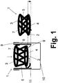
- Fig. 1 shows a Torsionswringer 1, comprising a receiving device 2 for receiving a mop head of a mop, wherein the receiving device 2 has an upper part 3 and a lower part 4, which are interconnected by elements 5.
- the elements 5 are configured and / or hinged to the parts 3, 4, that the parts 3, 4 are rotatable relative to each other.
- the elements 5 are movably hinged to the parts 3, 4 and can be pivoted and tilted.
- the Torsionswringer 1 has a base body 8, which is provided for coupling to a bucket 10.
- the receiving device 2 is movable relative to the base body 8.
- the receiving device 2 is axially displaceable by inserting the mop, wherein the lower part 4 relative to the upper part 3 by the displacement of the receiving device 2 is rotatable.
- the receiving device 2 is associated with a guide 6, 11, which rotates in a linear insertion of the mop in the receiving device 2, a part 4 against the other part 3.
- the upper part 3 is linearly guided by a linear guide 6 and not rotated, wherein the lower part 4 is rotated by a thread bend 11, namely, when sliding on the thread bow 11 is forced into rotation.
- the receiving device 2 is moved as a whole by an offset down.
- the offset is shown schematically by the downward arrow between the two dashed lines.
- the guide 6, 11 comprises a linear guide 6 and a thread bend eleventh
- the elements 5 are flexible.
- the elements 5 are integrally and of the same material with the parts 3, 4 configured.
- the elements 5 are configured lamellar.
- a mop is rotatable by the receiving device 2.
- the receiving device 2 has a space 7 which can be made smaller by rotating the parts 3, 4 relative to each other.
- the receiving device 2 is traceable by a return element 9 in an initial position.
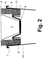
- Fig. 2 shows a Torsionswringer 1 ', comprising a receiving device 2' for receiving a mop head of a mop, wherein the receiving device 2 'has an upper part 3' and a lower part 4 ', which are interconnected by elements 5', as in Fig. 3 and 4 are shown.
- the elements 5 'are configured and / or hinged to the parts 3', 4 ', that the parts 3', 4 'are rotatable relative to each other.
- the elements 5 'are hinged to the parts 3', 4 'and can be bent and tilted.
- the Torsionswringer 1 ' has a base body 8', which is provided for coupling to a bucket 10 '.
- the receiving device 2 ' is axially movable relative to the main body 8'.
- the receiving device 2 ' is axially displaceable by inserting the mop, wherein the lower part 4' relative to the upper part 3 'by the displacement of the receiving device 2' is rotatable.
- the receiving device 2 ' is associated with a guide 6', 11 ', which in a linear insertion of the mop in the receiving device 2' the part 4 'against the other part 3' twisted.
- the upper part 3 ' is rotatably guided linearly, wherein the lower part 4' is linearly guided and at the same time rotatable.
- the upper part 3 ' is rotatably guided linearly by a linear guide 6', not rotated and moved downwards, wherein the lower part 4 'by the rotary guide 11' twisted and guided linearly downwards, namely forced into a rotation, which with a linear Downward movement is combined.
- the receiving device 2 ' is moved as a whole downwards, wherein the space 7' by the simultaneous rotation of the parts 3 ', 4' is reduced relative to each other.
- a mop, not shown, is therefore rotatable and wrenchable by the receiving device 2 '.
- Fig. 3 shows the basket-like receiving device 2 ', the upper part 3' is designed as an edge and the lower part 4 'as a bottom element.
- the elements 5 ' are flexible.
- the elements 5 ' are integrally and of the same material with the parts 3', 4 'configured.
- the elements 5 ' are configured lamellar.
- the elements 5 ' serve as return springs, by means of which the parts 3', 4 'can be brought at least partially into their starting position.
- At least one element 5 ' has at least two sections 5'a, 5'b, which merge into one another at a kink 5'd or are connected to one another. At least one element 5 'has two sections 5'a, 5'b, which are each inclined at different angles to the horizontal or against the parts 3', 4 '.
- an element 5 ' consists of three sections 5'a, 5'b, 5'c, of which, in the initial resting state, each is inclined at a different angle to the upper part 3' or the lower part 4 '.
- a first section 5'a hinged to the lower part 4 ' is the longest, a second, middle section 5'b is the second longest and a third section 5'c hinged to the upper part 3' is the shortest ,
- the first section 5'a tapers in the direction of the lower part 4 '.
- Fig. 4 shows a plan view of the receiving device 2 'according to Fig. 3 ,
Landscapes
- Cleaning Implements For Floors, Carpets, Furniture, Walls, And The Like (AREA)
- Coating Apparatus (AREA)
Priority Applications (1)
| Application Number | Priority Date | Filing Date | Title |
|---|---|---|---|
| PL14746950T PL3035835T3 (pl) | 2013-08-20 | 2014-07-02 | Wyżymaczka skrętna |
Applications Claiming Priority (2)
| Application Number | Priority Date | Filing Date | Title |
|---|---|---|---|
| DE102013013707 | 2013-08-20 | ||
| PCT/EP2014/001811 WO2015024611A1 (de) | 2013-08-20 | 2014-07-02 | Torsionswringer |
Publications (2)
| Publication Number | Publication Date |
|---|---|
| EP3035835A1 EP3035835A1 (de) | 2016-06-29 |
| EP3035835B1 true EP3035835B1 (de) | 2018-12-26 |
Family
ID=51263363
Family Applications (1)
| Application Number | Title | Priority Date | Filing Date |
|---|---|---|---|
| EP14746950.6A Active EP3035835B1 (de) | 2013-08-20 | 2014-07-02 | Torsionswringer |
Country Status (15)
| Country | Link |
|---|---|
| US (1) | US10123675B2 (pl) |
| EP (1) | EP3035835B1 (pl) |
| CN (1) | CN105491934B (pl) |
| AU (1) | AU2014310945B2 (pl) |
| BR (1) | BR112016002994B1 (pl) |
| CA (1) | CA2917084C (pl) |
| DE (1) | DE202014005331U1 (pl) |
| DK (1) | DK3035835T3 (pl) |
| ES (1) | ES2715100T3 (pl) |
| MX (1) | MX2016002163A (pl) |
| PL (1) | PL3035835T3 (pl) |
| PT (1) | PT3035835T (pl) |
| TR (1) | TR201903214T4 (pl) |
| TW (1) | TWI573550B (pl) |
| WO (1) | WO2015024611A1 (pl) |
Families Citing this family (4)
| Publication number | Priority date | Publication date | Assignee | Title |
|---|---|---|---|---|
| DE102015005948B8 (de) * | 2015-05-12 | 2017-01-26 | Carl Freudenberg Kg | Torsionswringer mit geringem Hub und Set aus Torsionswringer und Eimer |
| DE102016014403A1 (de) * | 2015-12-21 | 2017-06-22 | Carl Freudenberg Kg | Auswringvorrichtung für ein Wischgerät |
| CN113712476A (zh) * | 2021-07-09 | 2021-11-30 | 东阳市铭品日用品有限公司 | 一种拖把脱水组合结构的拧压件与挤拧压组件 |
| ES3019134A1 (es) | 2023-11-16 | 2025-05-20 | Sp Berner Plastic Group Sl | Escurridor de fregona de accionamiento vertical con movimiento de torsión para cubo friegasuelos |
Family Cites Families (13)
| Publication number | Priority date | Publication date | Assignee | Title |
|---|---|---|---|---|
| US560144A (en) * | 1896-05-12 | miohales | ||
| GB411330A (en) * | 1933-08-30 | 1934-06-07 | Edward Trezise Bunt | Improvements in or relating to mop-wringing appliances |
| US3406422A (en) * | 1966-08-22 | 1968-10-22 | Joseph J. Nichols | Mop wringer |
| US5611104A (en) * | 1996-05-24 | 1997-03-18 | Demars; Robert A. | Mop head wringer to be used with a bucket |
| US6065175A (en) * | 1998-08-13 | 2000-05-23 | Tejerina; Silvia Reyero | Flooring mopping system |
| DE10045525C1 (de) * | 2000-09-13 | 2002-02-07 | Freudenberg Carl Kg | Auswringvorrichtung |
| DE10102078C1 (de) * | 2001-01-18 | 2002-09-05 | Freudenberg Carl Kg | Auswringvorrichtung |
| CN2712266Y (zh) * | 2004-06-29 | 2005-07-27 | 张海杰 | 拖把挤水器连水桶 |
| DE102006045615B3 (de) | 2006-09-25 | 2007-10-11 | Carl Freudenberg Kg | Auswringvorrichtung |
| US20090265871A1 (en) * | 2008-04-24 | 2009-10-29 | Alvin Wooten | Floor cleaning system |
| TWM447206U (zh) * | 2012-06-18 | 2013-02-21 | Da Ding Energy Co Ltd | 拖把擰乾器 |
| US9161673B2 (en) * | 2012-06-26 | 2015-10-20 | 3M Innovative Properties Company | Wringer for a bucket |
| US20150282689A1 (en) * | 2012-08-08 | 2015-10-08 | E.D. Oates Pty Ltd | Mop bucket |
-
2014
- 2014-07-02 PL PL14746950T patent/PL3035835T3/pl unknown
- 2014-07-02 DE DE202014005331.6U patent/DE202014005331U1/de not_active Expired - Lifetime
- 2014-07-02 TR TR2019/03214T patent/TR201903214T4/tr unknown
- 2014-07-02 BR BR112016002994-1A patent/BR112016002994B1/pt not_active IP Right Cessation
- 2014-07-02 US US14/911,732 patent/US10123675B2/en active Active
- 2014-07-02 PT PT14746950T patent/PT3035835T/pt unknown
- 2014-07-02 ES ES14746950T patent/ES2715100T3/es active Active
- 2014-07-02 CN CN201480045710.4A patent/CN105491934B/zh active Active
- 2014-07-02 WO PCT/EP2014/001811 patent/WO2015024611A1/de not_active Ceased
- 2014-07-02 DK DK14746950.6T patent/DK3035835T3/en active
- 2014-07-02 MX MX2016002163A patent/MX2016002163A/es active IP Right Grant
- 2014-07-02 EP EP14746950.6A patent/EP3035835B1/de active Active
- 2014-07-02 CA CA2917084A patent/CA2917084C/en active Active
- 2014-07-02 AU AU2014310945A patent/AU2014310945B2/en active Active
- 2014-08-15 TW TW103128015A patent/TWI573550B/zh not_active IP Right Cessation
Non-Patent Citations (1)
| Title |
|---|
| None * |
Also Published As
| Publication number | Publication date |
|---|---|
| HK1217418A1 (zh) | 2017-01-13 |
| TR201903214T4 (tr) | 2019-03-21 |
| BR112016002994B1 (pt) | 2021-12-07 |
| TWI573550B (zh) | 2017-03-11 |
| PT3035835T (pt) | 2019-03-21 |
| DK3035835T3 (en) | 2019-04-08 |
| US20160183760A1 (en) | 2016-06-30 |
| EP3035835A1 (de) | 2016-06-29 |
| CA2917084C (en) | 2017-10-31 |
| BR112016002994A2 (pt) | 2017-08-01 |
| TW201524449A (zh) | 2015-07-01 |
| CA2917084A1 (en) | 2015-02-26 |
| US10123675B2 (en) | 2018-11-13 |
| PL3035835T3 (pl) | 2019-07-31 |
| AU2014310945A1 (en) | 2016-01-07 |
| AU2014310945B2 (en) | 2017-02-23 |
| DE202014005331U1 (de) | 2014-07-17 |
| CN105491934B (zh) | 2017-12-01 |
| CN105491934A (zh) | 2016-04-13 |
| ES2715100T3 (es) | 2019-05-31 |
| MX2016002163A (es) | 2016-06-23 |
| WO2015024611A1 (de) | 2015-02-26 |
Similar Documents
| Publication | Publication Date | Title |
|---|---|---|
| EP2068692B1 (de) | Auswringvorrichtung | |
| DE69725735T2 (de) | Auswringvorrichtung für wischgerät | |
| DE102011011662A1 (de) | Türverschluss für eine Spülmaschine | |
| EP2868250B1 (de) | Pressaufsatz für einen Eimer eines Wischsystems und Wischsystem | |
| EP3294104B1 (de) | Torsionswringer mit geringem hub | |
| WO2015024611A1 (de) | Torsionswringer | |
| DE102014113517B4 (de) | Selbstreinigendes Bürstensystem zum Reinigen von Oberflächen | |
| DE69833315T2 (de) | Wischgerät | |
| DE4222948A1 (de) | Schmetterlings-bodenwischer | |
| EP2211681A1 (de) | Flügelmopp | |
| DE102009000920A1 (de) | Vorrichtung zum Auspressen von Reinigungselementen | |
| DE102010015434A1 (de) | Borstenloser WC-Reinigungskopf | |
| EP3801170B1 (de) | Wischplatte | |
| DE102014101770B4 (de) | 3d-rotationsstaubbesen | |
| DE202012103004U1 (de) | Greifzange | |
| DE102007032108B4 (de) | Greifzange für Haushaltszwecke | |
| DE102009044150A1 (de) | Vorrichtung zum vollständigen Entleeren von Tuben | |
| DE202011005690U1 (de) | Wischer | |
| EP3078454A1 (de) | Vorrichtung mit paralleler greiffläche | |
| DE102016121266B4 (de) | Lösevorrichtung und System aus Lösevorrichtung und Moppbezughalter | |
| WO2016055327A1 (de) | Getränkezubereitungsvorrichtung | |
| DE1913419A1 (de) | Befestigungseinrichtung | |
| DE102009037071B4 (de) | Wischer mit verschwenkbar gelagerten Wischflügeln | |
| DE202013103543U1 (de) | Die Konstruktionsverbesserung eines automatischen Teleskopschirms, der durch die Verstärkung der Federkraft noch einfacher auf- und zuzumachen ist | |
| WO2014040698A1 (de) | Vorrichtung zum ausschleudern eines mopps mit zentriermitteln |
Legal Events
| Date | Code | Title | Description |
|---|---|---|---|
| PUAI | Public reference made under article 153(3) epc to a published international application that has entered the european phase |
Free format text: ORIGINAL CODE: 0009012 |
|
| 17P | Request for examination filed |
Effective date: 20160201 |
|
| AK | Designated contracting states |
Kind code of ref document: A1 Designated state(s): AL AT BE BG CH CY CZ DE DK EE ES FI FR GB GR HR HU IE IS IT LI LT LU LV MC MK MT NL NO PL PT RO RS SE SI SK SM TR |
|
| AX | Request for extension of the european patent |
Extension state: BA ME |
|
| DAX | Request for extension of the european patent (deleted) | ||
| RIN1 | Information on inventor provided before grant (corrected) |
Inventor name: HOHENHAUS, JOHANNES Inventor name: WALLBAUM, REINER Inventor name: DINGERT, UWE Inventor name: WEIS, NORBERT |
|
| RIN1 | Information on inventor provided before grant (corrected) |
Inventor name: WALLBAUM, REINER Inventor name: WEIS, NORBERT Inventor name: DINGERT, UWE Inventor name: HOHENHAUS, JOHANNES |
|
| GRAP | Despatch of communication of intention to grant a patent |
Free format text: ORIGINAL CODE: EPIDOSNIGR1 |
|
| STAA | Information on the status of an ep patent application or granted ep patent |
Free format text: STATUS: GRANT OF PATENT IS INTENDED |
|
| INTG | Intention to grant announced |
Effective date: 20180905 |
|
| GRAS | Grant fee paid |
Free format text: ORIGINAL CODE: EPIDOSNIGR3 |
|
| GRAA | (expected) grant |
Free format text: ORIGINAL CODE: 0009210 |
|
| STAA | Information on the status of an ep patent application or granted ep patent |
Free format text: STATUS: THE PATENT HAS BEEN GRANTED |
|
| AK | Designated contracting states |
Kind code of ref document: B1 Designated state(s): AL AT BE BG CH CY CZ DE DK EE ES FI FR GB GR HR HU IE IS IT LI LT LU LV MC MK MT NL NO PL PT RO RS SE SI SK SM TR |
|
| REG | Reference to a national code |
Ref country code: GB Ref legal event code: FG4D Free format text: NOT ENGLISH |
|
| REG | Reference to a national code |
Ref country code: CH Ref legal event code: EP |
|
| REG | Reference to a national code |
Ref country code: AT Ref legal event code: REF Ref document number: 1080270 Country of ref document: AT Kind code of ref document: T Effective date: 20190115 |
|
| REG | Reference to a national code |
Ref country code: IE Ref legal event code: FG4D Free format text: LANGUAGE OF EP DOCUMENT: GERMAN |
|
| REG | Reference to a national code |
Ref country code: DE Ref legal event code: R096 Ref document number: 502014010478 Country of ref document: DE |
|
| REG | Reference to a national code |
Ref country code: PT Ref legal event code: SC4A Ref document number: 3035835 Country of ref document: PT Date of ref document: 20190321 Kind code of ref document: T Free format text: AVAILABILITY OF NATIONAL TRANSLATION Effective date: 20190308 |
|
| REG | Reference to a national code |
Ref country code: SE Ref legal event code: TRGR |
|
| REG | Reference to a national code |
Ref country code: DK Ref legal event code: T3 Effective date: 20190401 |
|
| PG25 | Lapsed in a contracting state [announced via postgrant information from national office to epo] |
Ref country code: FI Free format text: LAPSE BECAUSE OF FAILURE TO SUBMIT A TRANSLATION OF THE DESCRIPTION OR TO PAY THE FEE WITHIN THE PRESCRIBED TIME-LIMIT Effective date: 20181226 Ref country code: BG Free format text: LAPSE BECAUSE OF FAILURE TO SUBMIT A TRANSLATION OF THE DESCRIPTION OR TO PAY THE FEE WITHIN THE PRESCRIBED TIME-LIMIT Effective date: 20190326 Ref country code: HR Free format text: LAPSE BECAUSE OF FAILURE TO SUBMIT A TRANSLATION OF THE DESCRIPTION OR TO PAY THE FEE WITHIN THE PRESCRIBED TIME-LIMIT Effective date: 20181226 Ref country code: LV Free format text: LAPSE BECAUSE OF FAILURE TO SUBMIT A TRANSLATION OF THE DESCRIPTION OR TO PAY THE FEE WITHIN THE PRESCRIBED TIME-LIMIT Effective date: 20181226 Ref country code: LT Free format text: LAPSE BECAUSE OF FAILURE TO SUBMIT A TRANSLATION OF THE DESCRIPTION OR TO PAY THE FEE WITHIN THE PRESCRIBED TIME-LIMIT Effective date: 20181226 Ref country code: NO Free format text: LAPSE BECAUSE OF FAILURE TO SUBMIT A TRANSLATION OF THE DESCRIPTION OR TO PAY THE FEE WITHIN THE PRESCRIBED TIME-LIMIT Effective date: 20190326 |
|
| REG | Reference to a national code |
Ref country code: NL Ref legal event code: MP Effective date: 20181226 |
|
| REG | Reference to a national code |
Ref country code: LT Ref legal event code: MG4D |
|
| PG25 | Lapsed in a contracting state [announced via postgrant information from national office to epo] |
Ref country code: RS Free format text: LAPSE BECAUSE OF FAILURE TO SUBMIT A TRANSLATION OF THE DESCRIPTION OR TO PAY THE FEE WITHIN THE PRESCRIBED TIME-LIMIT Effective date: 20181226 Ref country code: AL Free format text: LAPSE BECAUSE OF FAILURE TO SUBMIT A TRANSLATION OF THE DESCRIPTION OR TO PAY THE FEE WITHIN THE PRESCRIBED TIME-LIMIT Effective date: 20181226 |
|
| REG | Reference to a national code |
Ref country code: GR Ref legal event code: EP Ref document number: 20190400975 Country of ref document: GR Effective date: 20190524 |
|
| PG25 | Lapsed in a contracting state [announced via postgrant information from national office to epo] |
Ref country code: NL Free format text: LAPSE BECAUSE OF FAILURE TO SUBMIT A TRANSLATION OF THE DESCRIPTION OR TO PAY THE FEE WITHIN THE PRESCRIBED TIME-LIMIT Effective date: 20181226 |
|
| PG25 | Lapsed in a contracting state [announced via postgrant information from national office to epo] |
Ref country code: SM Free format text: LAPSE BECAUSE OF FAILURE TO SUBMIT A TRANSLATION OF THE DESCRIPTION OR TO PAY THE FEE WITHIN THE PRESCRIBED TIME-LIMIT Effective date: 20181226 Ref country code: EE Free format text: LAPSE BECAUSE OF FAILURE TO SUBMIT A TRANSLATION OF THE DESCRIPTION OR TO PAY THE FEE WITHIN THE PRESCRIBED TIME-LIMIT Effective date: 20181226 Ref country code: RO Free format text: LAPSE BECAUSE OF FAILURE TO SUBMIT A TRANSLATION OF THE DESCRIPTION OR TO PAY THE FEE WITHIN THE PRESCRIBED TIME-LIMIT Effective date: 20181226 Ref country code: SK Free format text: LAPSE BECAUSE OF FAILURE TO SUBMIT A TRANSLATION OF THE DESCRIPTION OR TO PAY THE FEE WITHIN THE PRESCRIBED TIME-LIMIT Effective date: 20181226 Ref country code: IS Free format text: LAPSE BECAUSE OF FAILURE TO SUBMIT A TRANSLATION OF THE DESCRIPTION OR TO PAY THE FEE WITHIN THE PRESCRIBED TIME-LIMIT Effective date: 20190426 |
|
| REG | Reference to a national code |
Ref country code: DE Ref legal event code: R097 Ref document number: 502014010478 Country of ref document: DE |
|
| PLBE | No opposition filed within time limit |
Free format text: ORIGINAL CODE: 0009261 |
|
| STAA | Information on the status of an ep patent application or granted ep patent |
Free format text: STATUS: NO OPPOSITION FILED WITHIN TIME LIMIT |
|
| 26N | No opposition filed |
Effective date: 20190927 |
|
| PG25 | Lapsed in a contracting state [announced via postgrant information from national office to epo] |
Ref country code: MC Free format text: LAPSE BECAUSE OF FAILURE TO SUBMIT A TRANSLATION OF THE DESCRIPTION OR TO PAY THE FEE WITHIN THE PRESCRIBED TIME-LIMIT Effective date: 20181226 Ref country code: SI Free format text: LAPSE BECAUSE OF FAILURE TO SUBMIT A TRANSLATION OF THE DESCRIPTION OR TO PAY THE FEE WITHIN THE PRESCRIBED TIME-LIMIT Effective date: 20181226 |
|
| PG25 | Lapsed in a contracting state [announced via postgrant information from national office to epo] |
Ref country code: LU Free format text: LAPSE BECAUSE OF NON-PAYMENT OF DUE FEES Effective date: 20190702 |
|
| PG25 | Lapsed in a contracting state [announced via postgrant information from national office to epo] |
Ref country code: IE Free format text: LAPSE BECAUSE OF NON-PAYMENT OF DUE FEES Effective date: 20190702 |
|
| PG25 | Lapsed in a contracting state [announced via postgrant information from national office to epo] |
Ref country code: CY Free format text: LAPSE BECAUSE OF FAILURE TO SUBMIT A TRANSLATION OF THE DESCRIPTION OR TO PAY THE FEE WITHIN THE PRESCRIBED TIME-LIMIT Effective date: 20181226 |
|
| PG25 | Lapsed in a contracting state [announced via postgrant information from national office to epo] |
Ref country code: HU Free format text: LAPSE BECAUSE OF FAILURE TO SUBMIT A TRANSLATION OF THE DESCRIPTION OR TO PAY THE FEE WITHIN THE PRESCRIBED TIME-LIMIT; INVALID AB INITIO Effective date: 20140702 Ref country code: MT Free format text: LAPSE BECAUSE OF FAILURE TO SUBMIT A TRANSLATION OF THE DESCRIPTION OR TO PAY THE FEE WITHIN THE PRESCRIBED TIME-LIMIT Effective date: 20181226 |
|
| PG25 | Lapsed in a contracting state [announced via postgrant information from national office to epo] |
Ref country code: MK Free format text: LAPSE BECAUSE OF FAILURE TO SUBMIT A TRANSLATION OF THE DESCRIPTION OR TO PAY THE FEE WITHIN THE PRESCRIBED TIME-LIMIT Effective date: 20181226 |
|
| PGFP | Annual fee paid to national office [announced via postgrant information from national office to epo] |
Ref country code: ES Payment date: 20250812 Year of fee payment: 12 |
|
| PGFP | Annual fee paid to national office [announced via postgrant information from national office to epo] |
Ref country code: DK Payment date: 20250725 Year of fee payment: 12 Ref country code: DE Payment date: 20250728 Year of fee payment: 12 |
|
| PGFP | Annual fee paid to national office [announced via postgrant information from national office to epo] |
Ref country code: GR Payment date: 20250722 Year of fee payment: 12 |
|
| PGFP | Annual fee paid to national office [announced via postgrant information from national office to epo] |
Ref country code: IT Payment date: 20250721 Year of fee payment: 12 |
|
| PGFP | Annual fee paid to national office [announced via postgrant information from national office to epo] |
Ref country code: BE Payment date: 20250724 Year of fee payment: 12 Ref country code: GB Payment date: 20250722 Year of fee payment: 12 |
|
| PGFP | Annual fee paid to national office [announced via postgrant information from national office to epo] |
Ref country code: AT Payment date: 20250718 Year of fee payment: 12 Ref country code: FR Payment date: 20250725 Year of fee payment: 12 |
|
| PGFP | Annual fee paid to national office [announced via postgrant information from national office to epo] |
Ref country code: CH Payment date: 20250801 Year of fee payment: 12 Ref country code: SE Payment date: 20250725 Year of fee payment: 12 |
|
| PGFP | Annual fee paid to national office [announced via postgrant information from national office to epo] |
Ref country code: PL Payment date: 20260608 Year of fee payment: 13 |
|
| PGFP | Annual fee paid to national office [announced via postgrant information from national office to epo] |
Ref country code: PT Payment date: 20260605 Year of fee payment: 13 |
|
| PGFP | Annual fee paid to national office [announced via postgrant information from national office to epo] |
Ref country code: CZ Payment date: 20260624 Year of fee payment: 13 Ref country code: TR Payment date: 20260612 Year of fee payment: 13 |
|
| REG | Reference to a national code |
Ref country code: CH Ref legal event code: U11 Free format text: ST27 STATUS EVENT CODE: U-0-0-U10-U11 (AS PROVIDED BY THE NATIONAL OFFICE) Effective date: 20260801 |