EP3034059A1 - Operationstische und zubehör - Google Patents
Operationstische und zubehör Download PDFInfo
- Publication number
- EP3034059A1 EP3034059A1 EP15189548.9A EP15189548A EP3034059A1 EP 3034059 A1 EP3034059 A1 EP 3034059A1 EP 15189548 A EP15189548 A EP 15189548A EP 3034059 A1 EP3034059 A1 EP 3034059A1
- Authority
- EP
- European Patent Office
- Prior art keywords
- limb
- support
- accessory
- operating table
- pad
- Prior art date
- Legal status (The legal status is an assumption and is not a legal conclusion. Google has not performed a legal analysis and makes no representation as to the accuracy of the status listed.)
- Withdrawn
Links
Images


Classifications
-
- A—HUMAN NECESSITIES
- A61—MEDICAL OR VETERINARY SCIENCE; HYGIENE
- A61G—TRANSPORT, PERSONAL CONVEYANCES, OR ACCOMMODATION SPECIALLY ADAPTED FOR PATIENTS OR DISABLED PERSONS; OPERATING TABLES OR CHAIRS; CHAIRS FOR DENTISTRY; FUNERAL DEVICES
- A61G13/00—Operating tables; Auxiliary appliances therefor
- A61G13/0036—Orthopaedic operating tables
- A61G13/0081—Orthopaedic operating tables specially adapted for hip surgeries
-
- A—HUMAN NECESSITIES
- A61—MEDICAL OR VETERINARY SCIENCE; HYGIENE
- A61G—TRANSPORT, PERSONAL CONVEYANCES, OR ACCOMMODATION SPECIALLY ADAPTED FOR PATIENTS OR DISABLED PERSONS; OPERATING TABLES OR CHAIRS; CHAIRS FOR DENTISTRY; FUNERAL DEVICES
- A61G13/00—Operating tables; Auxiliary appliances therefor
- A61G13/02—Adjustable operating tables; Controls therefor
- A61G13/04—Adjustable operating tables; Controls therefor tiltable around transverse or longitudinal axis
-
- A—HUMAN NECESSITIES
- A61—MEDICAL OR VETERINARY SCIENCE; HYGIENE
- A61G—TRANSPORT, PERSONAL CONVEYANCES, OR ACCOMMODATION SPECIALLY ADAPTED FOR PATIENTS OR DISABLED PERSONS; OPERATING TABLES OR CHAIRS; CHAIRS FOR DENTISTRY; FUNERAL DEVICES
- A61G13/00—Operating tables; Auxiliary appliances therefor
- A61G13/10—Parts, details or accessories
- A61G13/101—Clamping means for connecting accessories to the operating table
-
- A—HUMAN NECESSITIES
- A61—MEDICAL OR VETERINARY SCIENCE; HYGIENE
- A61G—TRANSPORT, PERSONAL CONVEYANCES, OR ACCOMMODATION SPECIALLY ADAPTED FOR PATIENTS OR DISABLED PERSONS; OPERATING TABLES OR CHAIRS; CHAIRS FOR DENTISTRY; FUNERAL DEVICES
- A61G13/00—Operating tables; Auxiliary appliances therefor
- A61G13/10—Parts, details or accessories
- A61G13/12—Rests specially adapted therefor; Arrangements of patient-supporting surfaces
- A61G13/1205—Rests specially adapted therefor; Arrangements of patient-supporting surfaces for specific parts of the body
- A61G13/1245—Knees, upper or lower legs
-
- A—HUMAN NECESSITIES
- A61—MEDICAL OR VETERINARY SCIENCE; HYGIENE
- A61G—TRANSPORT, PERSONAL CONVEYANCES, OR ACCOMMODATION SPECIALLY ADAPTED FOR PATIENTS OR DISABLED PERSONS; OPERATING TABLES OR CHAIRS; CHAIRS FOR DENTISTRY; FUNERAL DEVICES
- A61G13/00—Operating tables; Auxiliary appliances therefor
- A61G13/10—Parts, details or accessories
- A61G13/12—Rests specially adapted therefor; Arrangements of patient-supporting surfaces
- A61G13/1205—Rests specially adapted therefor; Arrangements of patient-supporting surfaces for specific parts of the body
- A61G13/125—Ankles or feet
-
- A—HUMAN NECESSITIES
- A61—MEDICAL OR VETERINARY SCIENCE; HYGIENE
- A61G—TRANSPORT, PERSONAL CONVEYANCES, OR ACCOMMODATION SPECIALLY ADAPTED FOR PATIENTS OR DISABLED PERSONS; OPERATING TABLES OR CHAIRS; CHAIRS FOR DENTISTRY; FUNERAL DEVICES
- A61G2200/00—Information related to the kind of patient or his position
- A61G2200/30—Specific positions of the patient
- A61G2200/32—Specific positions of the patient lying
- A61G2200/327—Specific positions of the patient lying supine
-
- A—HUMAN NECESSITIES
- A61—MEDICAL OR VETERINARY SCIENCE; HYGIENE
- A61G—TRANSPORT, PERSONAL CONVEYANCES, OR ACCOMMODATION SPECIALLY ADAPTED FOR PATIENTS OR DISABLED PERSONS; OPERATING TABLES OR CHAIRS; CHAIRS FOR DENTISTRY; FUNERAL DEVICES
- A61G2210/00—Devices for specific treatment or diagnosis
- A61G2210/10—Devices for specific treatment or diagnosis for orthopedics
Definitions
- an osteotomy of the femur is performed and, once the final neck cut has been made at the preoperatively planned osteotomy level, the femoral head can be twisted to rupture the ligamentum teres. This facilitates later dislocation of the joint. Distraction and external rotation of the leg can also be applied to create room for the removal of the femoral head.
- retractors are used to expose the acetabulum, which is then reamed and a new acetabular cup is implanted in the conventional way.
- the leg is then positioned in slight adduction and significant external rotation to expose the proximal femur.
- the femur is progressively lifted until the osteotomy plane can be reached through the skin incision.
- the femur can be lifted in a number of ways, such as manually with a bone hook.
- the thrust element can be used to provide the locating feature of the floor-standing component.
- the accessory may be designed so that the patient support has a notch as a locating feature, the thrust element has a pair of outwardly facing guide channels on either side as a locating feature, each guide channel having an outwardly facing base surface, the notch and the guide channels being adapted to locate the two components relative to each other by receipt of the thrust element into the notch and by receipt of the margins of the patient support adjacent to the sides of the notch into respective guide channels.
- the guide channels and the margins of the patient support adjacent to the sides of the notch should be so shaped as to allow the patient support and the thrust element to tilt relative to one another, thus allowing the table to be tilted relative to the floor-standing component while continuing to locate the components relative to each other.
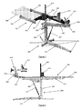
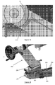
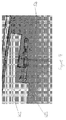
- the attachment of the side frame members 101, 102 of the table-mounted component 100 to the operating table is illustrated in figure 3 in respect of the left side frame member 101.
- Attached to the left side frame member 101 is a plurality of E-shaped frame hangers 106, each of which is symmetrically shaped so as to be able to fit onto the side rail 310 of the operating table 300 both in the position shown in the figure and in an inverted position.
- This is to enable either side frame member 101, 102 to be assembled onto either side of the operating table without having to reverse the hangers, which in turn enables the same accessory to be conveniently used for left or right hip replacement.
- the frame member is for convenience illustrated as terminating just proximally of the proximal E-shaped hanger, but in practice it extends beyond it as illustrated in figure 4a .
- the side frame member 101 includes at its distal end a pair of brackets 108, one upper and the other lower.
- the patient support plate 103 includes at the operative side of its distal end a cut-away 109 that facilitates manipulation of the operative limb.
- the patient support plate 103 includes a transverse countersunk slot 110.
- a locating peg (not shown) can be dropped into the countersunk slot to pass through a locating aperture in the upper bracket 108. The head of the peg locates in the countersunk recess of the slot 110, and this locates the patient support plate 103 in the distal and proximal direction.
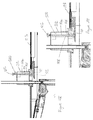
- each clamping plate is a short channel-section stainless steel clamp with upper and lower arms 115 and a midsection 116 joining the arms 115.
- the midsection has a slot 117 through which the shaft of a knurled screw (not shown) passes, to be retained by a captive bolt. Loosening the knurled screw allows the clamping plate 114 to be lifted from the locking position of figure 5b in which the locating pegs are obscured, to the released position in figure 5a , in which they are accessible, allowing the patient support plate to be relocated.
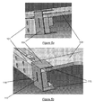
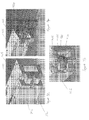
- the structure of the thrust spacer 212 is illustrated in figure 7 , again along with certain dimensions in millimetres.
- the thrust spacer 212 has an upper section 213 and a lower section 214 in the overall form of a flange and a vertical through-bore 215 for sliding receipt of the reaction post 204.
- the upper section 213 has a radiused thrust surface 216 horizontally spaced from the vertical bore 215.
- the lower flange section 214 is furnished on either side with a guide channel 217.
- Each guide channel 217 has crowned upper and lower surfaces 218, 219, and an outwardly facing base surface 220. At their closest, the upper and lower surfaces are 18 mm apart.
- the base surfaces are 66 mm apart and the distal end 221 of the lower section 213 is radiused to match the radiused end 120 of the notch 118 in the patient support plate 103.
- Both the patient support 103 and the thrust spacer 212 are constructed from a radiolucent material, such as reinforced polymer composites (e.g. glass fibre or carbon fibre composites), epoxy, polyether-ether-ketone (PEEK), thermoplastics, polyketones or polycarbonates, or any other radiolucent material with suitable mechanical properties, thus enabling X-ray imaging of the hip joint during surgery.
- a radiolucent material such as reinforced polymer composites (e.g. glass fibre or carbon fibre composites), epoxy, polyether-ether-ketone (PEEK), thermoplastics, polyketones or polycarbonates, or any other radiolucent material with suitable mechanical properties, thus enabling X-ray imaging of the hip joint during surgery.
- an X-ray grid may be provided for attachment to the patient support, or the patient support may incorporate such a grid.
- the grid may be a simple mesh of radiopaque material, such as a metallic mesh, which can be fastened or screwed to the underside of the patient support plate 103, or insert-moulded or otherwise incorporated into the structure of the patient support plate 103.
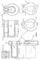
- FIG. 27-30 A further alternative reversible retaining mechanism is illustrated in figures 27-30 .
- the thrust spacer 212 is furnished with a vertical latching rod 500 that passes through it from top to bottom.
- the latching rod 500 has a knob 502 at its upper end, this being fitted to the upper end of a relatively narrow upper section 504 of the latching rod 500.
- This upper section 504 of the latching rod 500 passes through a relatively small hole in the upper section of the thrust spacer 212.
- the lower section 506 of the latching rod 500 is relatively wide and passes through a relatively large hole in the lower section of the thrust spacer 212.
- the latching rod 500 By pulling the knob 502, the latching rod 500 can be raised from the lowered position shown in figure 29 to the elevated position shown in figure 28 .
- some mechanism can be provided to prevent the latching rod 500 from being elevated beyond the position shown in figure 28 , as further elevation may cause the lower section 506 to disengage from the relatively large hole in the lower section of the thrust spacer 212, making its return to the lowered position rather tricky.
- a feature could be introduced into the interior of the thrust spacer 212 against which a shoulder 508 between the upper and lower sections 504, 506 of the latching rod 500 abuts in the elevated position.
- the latching rod may be spring-biased into the lowered position, or gravity may be left to do the trick.
- the patient support plate 103 is in this case furnished with a distally projecting tongue 510, which slides beneath the thrust spacer 212 as the two parts are brought into engagement.
- This tongue 510 has a vertical latching bore 512 which, when the thrust spacer 212 and the patient support plate 103 arc properly engaged, is in alignment with the latching rod 500, thus allowing the latching rod 500 to drop into the latching bore 512.
- the latching bore 512 is flared, to accommodate tilting of the patient support plate 103 relative to the thrust spacer 212 (two extreme positions of the patient support plate 103 are shown in figure 30 ). An equally effective alternative would be to taper the lower end of the latching rod 500.
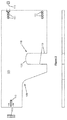
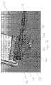
- Figure 10 shows the attachment and articulation of the support beam 205 to the reaction post 204.
- the proximal end of the support beam 205 includes a two-piece swivel housing 223 affixed around the reaction post 204 and a two-piece articulation housing 224 affixed about the distal end of the swivel housing 223 at the proximal articulation 206.
- the two-piece swivel housing 223 is shown in figure 11 and includes a first piece 225 and a second piece 226, each of which includes a half-bore 227 with a locating groove 228 at about its mid-point.
- a ratchet gear 234 Sandwiched between the two pieces of the swivel housing 225, 226 is a ratchet gear 234 having upper and lower arms 235, each with a lug 236 through each of which one of the fixing bolts 229 passes.
- the gear 234 includes a toothed, part-circular outer surface 237 and in inwardly facing tab. A shape corresponding to that of the ratchet gear is let into each of the two pieces of the swivel housing 225, 226, so as to retain the gear securely in place.
- Figure 14 shows a releasable ratchet pawl 249 within the articulation housing that engages the ratchet gear 234.
- the ratchet pawl 249 is mounted to pivot about a boss 250 provided for that purpose at its centre.
- the toothed end of the ratchet pawl 249 engages the ratchet gear 234 and the other end is pivotally attached to a clevis 251 at one end of a push-rod 252 that extends along much of the length of the support beam 205.
- the push-rod 252 attaches to a handle 253 positioned at the proximal end of the support beam 205.
- a spring biases the pawl 249 into engagement with the gear 234.
- the handed table-mounted component can also be improved for greater convenience when a bilateral hip operation is to be performed.
- the table-mounted component 100 of figure 1 is shown set up for an operation on the right hip joint. If it is to be used in a bilateral operation, it must be reconfigured when the operation on the right hip joint is complete. This involves swapping the side frame members 101, 102, together with their hangers 106, so that the longer of the two is now on the right side and the other way up, and reinstalling the patient support plate 103 the other way up too, so that the cut-away 109 is on the left side.
- the passive leg support plate 105 also needs to be moved and reinstalled in a different position on the longer side frame member 102.
- a swing bracket 410 is carried by the movable portion 402, mounted on a vertical pivot or pivots 411.
- the swing bracket 410 is able to swing out by 90o and locates the underside of the leg support plate 408 by means of a pin and a cooperating recess (not shown).
- the roller is in two parts, a body 421 and a cap 422.
- the cap 422 and the body 421 can collapse telescopically to a limited extent, but biased by an internal spring (not shown) into the expanded state illustrated.
- This enables the provision of angular positioning features (not shown) on the bracket extension 418 and the flat end of the roller body 421 by means of which the angular position of the roller can be set.
- An example of such angular positioning features would be a series of regularly angularly spaced countersunk holes 422 in the flat end of the roller body 421 and a locating pin on the bracket extension 418.
Landscapes
- Health & Medical Sciences (AREA)
- Engineering & Computer Science (AREA)
- Biomedical Technology (AREA)
- Life Sciences & Earth Sciences (AREA)
- Animal Behavior & Ethology (AREA)
- General Health & Medical Sciences (AREA)
- Public Health (AREA)
- Veterinary Medicine (AREA)
- Orthopedic Medicine & Surgery (AREA)
- Accommodation For Nursing Or Treatment Tables (AREA)
- Surgical Instruments (AREA)
Applications Claiming Priority (3)
| Application Number | Priority Date | Filing Date | Title |
|---|---|---|---|
| GBGB1115391.3A GB201115391D0 (en) | 2011-09-06 | 2011-09-06 | Operating tables and accessories |
| GBGB1118051.0A GB201118051D0 (en) | 2011-09-06 | 2011-10-19 | Operating tables and accessories |
| EP12759177.4A EP2753286B1 (de) | 2011-09-06 | 2012-09-06 | Operationstische und zubehör |
Related Parent Applications (1)
| Application Number | Title | Priority Date | Filing Date |
|---|---|---|---|
| EP12759177.4A Division EP2753286B1 (de) | 2011-09-06 | 2012-09-06 | Operationstische und zubehör |
Publications (1)
| Publication Number | Publication Date |
|---|---|
| EP3034059A1 true EP3034059A1 (de) | 2016-06-22 |
Family
ID=44882291
Family Applications (2)
| Application Number | Title | Priority Date | Filing Date |
|---|---|---|---|
| EP12759177.4A Not-in-force EP2753286B1 (de) | 2011-09-06 | 2012-09-06 | Operationstische und zubehör |
| EP15189548.9A Withdrawn EP3034059A1 (de) | 2011-09-06 | 2012-09-06 | Operationstische und zubehör |
Family Applications Before (1)
| Application Number | Title | Priority Date | Filing Date |
|---|---|---|---|
| EP12759177.4A Not-in-force EP2753286B1 (de) | 2011-09-06 | 2012-09-06 | Operationstische und zubehör |
Country Status (15)
| Country | Link |
|---|---|
| US (1) | US20140215718A1 (de) |
| EP (2) | EP2753286B1 (de) |
| JP (1) | JP2014525302A (de) |
| KR (1) | KR20140091670A (de) |
| CN (1) | CN103917212A (de) |
| AU (1) | AU2012306083A1 (de) |
| BR (1) | BR112014005108A2 (de) |
| CA (1) | CA2848020A1 (de) |
| ES (1) | ES2559459T3 (de) |
| GB (2) | GB201115391D0 (de) |
| HK (1) | HK1199704A1 (de) |
| MX (1) | MX2014002582A (de) |
| RU (1) | RU2014113412A (de) |
| WO (1) | WO2013034916A1 (de) |
| ZA (1) | ZA201402322B (de) |
Families Citing this family (38)
| Publication number | Priority date | Publication date | Assignee | Title |
|---|---|---|---|---|
| US9161875B2 (en) | 2012-09-07 | 2015-10-20 | Allen Medical Systems, Inc. | Multi-axis joint for a spar of a limb holder |
| US8997284B2 (en) * | 2012-11-15 | 2015-04-07 | Innovative Orthopedic Technologies, Llc | Surgical table with pivotable femoral support |
| EP2873405B1 (de) * | 2013-11-18 | 2016-05-18 | Schaerer Medical Management AG | Modularer operationstisch |
| US20150196447A1 (en) * | 2014-01-13 | 2015-07-16 | Athello, Inc. | Lower Extremity Positioning Assembly And Table Extension |
| DE102014100444B4 (de) * | 2014-01-16 | 2017-06-29 | MAQUET GmbH | Vorrichtung zum linearen Verschieben einer Patientenlagerfläche und Verfahren zur Montage einer derartigen Vorrichtung |
| US9254179B2 (en) * | 2014-04-17 | 2016-02-09 | Baycare Clinic, Llp | Surgical support system |
| EP2944259A1 (de) * | 2014-05-15 | 2015-11-18 | Buck Engineering & Consulting GmbH | Patientenpositioniereinrichtung |
| JP5754680B1 (ja) * | 2014-07-29 | 2015-07-29 | サージカルアライアンス株式会社 | 下肢関節手術用牽引手術台、接続マットユニット及び下肢関節手術用牽引手術台設置・収納システム |
| AT520654B1 (de) * | 2015-04-22 | 2019-11-15 | Implantech Medizintechnik Ges M B H | Vorrichtung zur Positionierung der unteren Gliedmaßen eines Patienten während einer Operation |
| AT14928U1 (de) * | 2015-04-22 | 2016-08-15 | Implantech Medizintechnik Ges M B H | Vorrichtung zur Positionierung der unteren Gliedmaßen eines Patienten während einer Operation |
| RU2592784C1 (ru) * | 2015-04-30 | 2016-07-27 | Дмитрий Николаевич Царев | Ортопедическое устройство для артроскопии коленного сустава |
| JP6406673B2 (ja) * | 2015-05-14 | 2018-10-17 | サージカルアライアンス株式会社 | 下肢関節手術用牽引手術台、接続マットユニット及び下肢関節手術用牽引手術台設置・収納システム |
| US11382816B2 (en) | 2015-06-05 | 2022-07-12 | Stryker Corporation | Surgical table and accessories to facilitate hip arthroscopy |
| GB2541177A (en) * | 2015-07-30 | 2017-02-15 | Univ Of The West Of England Bristol | Apparatus for performing fracture reduction |
| CN108135711B (zh) * | 2015-08-27 | 2021-10-08 | 黑普创新技术有限责任公司 | 用于移除髋关节置换假体的组件的手术托盘、器械以及方法 |
| KR20180045855A (ko) * | 2015-08-28 | 2018-05-04 | 마쿠에트 게엠베하 | 수술대에 액세서리를 고정하기 위한 디바이스 |
| KR101646880B1 (ko) * | 2015-10-05 | 2016-08-09 | (주)한림의료기 | 사지세척 및 소독용 다축견인 로봇 시스템 |
| CN105213149A (zh) * | 2015-10-23 | 2016-01-06 | 重庆医科大学附属儿童医院 | 一种手术床 |
| ITUA20162775A1 (it) | 2016-04-21 | 2017-10-21 | Medacta Int Sa | Piano adattatore per tavolo chirurgico e tavolo chirurgico |
| CN106389054A (zh) * | 2016-11-17 | 2017-02-15 | 宁波龙圣医疗器械有限公司 | 一种用于髋关节修复/置换手术的手术台支撑装置 |
| CA3052654A1 (en) | 2017-02-06 | 2018-08-09 | Stryker Corp. | Method and apparatus for supporting and stabilizing a patient during hip distraction |
| WO2018145096A1 (en) | 2017-02-06 | 2018-08-09 | Stryker Corp. | Anatomical gripping system for gripping the leg and foot of a patient when effecting hip distraction and/or when effecting leg positioning |
| WO2018145108A1 (en) | 2017-02-06 | 2018-08-09 | Stryker Corp. | Distraction frame for effecting hip distraction |
| EP3357472A1 (de) | 2017-02-07 | 2018-08-08 | Koninklijke Philips N.V. | Gleitende zubehörschiene zum halten von ausrüstung an einer patientenliege |
| DE102017110719A1 (de) | 2017-05-17 | 2018-11-22 | MAQUET GmbH | Chirurgisches Rotationsaggregat mit verbesserter Rotationsverriegelung |
| USD878836S1 (en) | 2017-08-17 | 2020-03-24 | Stryker Corp. | Table extender |
| CN108309378A (zh) * | 2018-02-09 | 2018-07-24 | 佳木斯大学 | 一种泌尿外科手术保护器 |
| WO2019214779A1 (de) * | 2018-05-07 | 2019-11-14 | Condor Medtec Gmbh | Extensions-fussmanschette |
| CN109223425B (zh) * | 2018-07-09 | 2020-11-06 | 青岛大学附属医院 | 一种妇产科检查座椅 |
| JP6609872B2 (ja) * | 2018-08-27 | 2019-11-27 | サージカルアライアンス株式会社 | 下肢関節手術用牽引手術台、接続マットユニット及び下肢関節手術用牽引手術台設置・収納システム |
| US10611391B1 (en) * | 2018-10-05 | 2020-04-07 | Corindus, Inc. | Mobile support and storage system for a medical device |
| CN109602564B (zh) * | 2018-12-05 | 2020-12-29 | 李宝京 | 一种便于取放药物的骨科换药架 |
| US11690749B2 (en) * | 2019-03-12 | 2023-07-04 | Mizuho Orthopedic Systems, Inc. | Systems and devices for providing lift assistance for a surgical procedure |
| US11497669B2 (en) | 2019-04-27 | 2022-11-15 | Ethicon, Inc. | Systems, devices, and methods for testing suture performance under static and dynamic conditions |
| US11564855B2 (en) | 2020-09-28 | 2023-01-31 | Stryker Corporation | Systems and methods for supporting and stabilizing a patient during hip distraction |
| CN113520779B (zh) * | 2021-07-01 | 2022-06-07 | 毛兴佳 | 一种骨科关节截骨置换器械 |
| CN113520778B (zh) * | 2021-07-01 | 2022-06-07 | 毛兴佳 | 一种骨科关节置换手术定位平台 |
| IT202200009863A1 (it) * | 2022-05-12 | 2023-11-12 | Clyde Ep Tech S R L | Supporto dinamico per il corpo umano per il trattamento delle patologie ortopediche e traumautologiche degli arti ed assieme modulare comprendente tale supporto dinamico |
Citations (8)
| Publication number | Priority date | Publication date | Assignee | Title |
|---|---|---|---|---|
| US4527555A (en) | 1981-05-18 | 1985-07-09 | Hermann Ruf | Auxiliary table for extension and repositioning in medical operations |
| US6286164B1 (en) | 1998-03-19 | 2001-09-11 | Orthopedic Systems, Inc. | Medical table having controlled movement and method of use |
| US20040133979A1 (en) * | 2003-01-13 | 2004-07-15 | Newkirk David C. | Orthopedic table apparatus |
| US20060051077A1 (en) | 2004-08-24 | 2006-03-09 | Fujitsu Limited | Rapid thermal processing apparatus and method of manufacture of semiconductor device |
| US20060064103A1 (en) | 2004-09-01 | 2006-03-23 | Matta Joel M | Surgical support for femur |
| WO2007080454A2 (en) | 2005-11-30 | 2007-07-19 | Smith & Nephew, Inc | Hip distraction |
| US7316040B2 (en) | 2004-06-08 | 2008-01-08 | Medacta International S.A. | System and method for positioning patient limbs during surgical procedures |
| US20100263129A1 (en) | 2009-02-24 | 2010-10-21 | Emad Aboujaoude | Lower Extremity Surgical Positioning Device |
Family Cites Families (30)
| Publication number | Priority date | Publication date | Assignee | Title |
|---|---|---|---|---|
| US2475003A (en) * | 1945-01-02 | 1949-07-05 | Lewis M Black | Body manipulation apparatus |
| US3766384A (en) * | 1971-04-28 | 1973-10-16 | Tower Co Inc | Surgical table |
| EP0086881B1 (de) * | 1982-02-19 | 1986-07-30 | Contraves Ag | Operationstisch |
| US4583725A (en) * | 1985-03-05 | 1986-04-22 | Arnold Roger D | Patient support frame for posterior lumbar laminectomy |
| US4964400A (en) * | 1988-04-19 | 1990-10-23 | Lincoln Mills, Inc. | Surgical limb supporting apparatus with tension measuring device |
| US4886258A (en) * | 1988-08-24 | 1989-12-12 | Scott James W | Well leg operative support |
| US5135210A (en) * | 1989-05-01 | 1992-08-04 | Michelson Gary K | Surgical armboard attachment device |
| US5131106A (en) * | 1990-08-30 | 1992-07-21 | Jackson Roger P | Spinal surgery table |
| US5088706A (en) * | 1990-08-30 | 1992-02-18 | Jackson Roger P | Spinal surgery table |
| CN2183170Y (zh) * | 1993-06-07 | 1994-11-23 | 张立 | 多用经后路途径外科手术床 |
| US5658315A (en) * | 1994-02-23 | 1997-08-19 | Orthopedic Systems, Inc. | Apparatus and method for lower limb traction |
| US5515562A (en) * | 1994-06-24 | 1996-05-14 | Health Care Solutions, Inc. | Sacral and perineal pads |
| US5645079A (en) * | 1994-12-02 | 1997-07-08 | Zahiri; Hormoz | Apparatus for mechanically holding, maneuvering and maintaining a body part of a patient during orthopedic surgery |
| US5613254A (en) * | 1994-12-02 | 1997-03-25 | Clayman; Ralph V. | Radiolucent table for supporting patients during medical procedures |
| IL117345A0 (en) * | 1996-03-04 | 1996-07-23 | Gotfried Yechiel | Height-adjustable support for lower-limb operations |
| US6260220B1 (en) * | 1997-02-13 | 2001-07-17 | Orthopedic Systems, Inc. | Surgical table for lateral procedures |
| US6237172B1 (en) * | 1998-10-01 | 2001-05-29 | Morgan Medesign, Inc. | Patient support table |
| US6315718B1 (en) * | 1999-10-04 | 2001-11-13 | Minnesota Scientific, Inc. | Method for hip retraction |
| AU7515201A (en) * | 2000-06-02 | 2001-12-17 | Hill Rom Services Inc | Foot support for a patient support |
| JP2005168881A (ja) * | 2003-12-12 | 2005-06-30 | Mizuho Co Ltd | 被検者支持装置 |
| US7669262B2 (en) * | 2004-11-10 | 2010-03-02 | Allen Medical Systems, Inc. | Accessory frame for spinal surgery |
| US7600281B2 (en) * | 2004-11-10 | 2009-10-13 | Allen Medical Systems, Inc. | Body support apparatus for spinal surgery |
| US7520007B2 (en) * | 2004-11-10 | 2009-04-21 | Allen Medical Systems, Inc. | Accessory rail clamp with latch and lock mechanisms |
| US7520008B2 (en) * | 2004-11-10 | 2009-04-21 | Allen Medical Systems | Surgical table extension |
| US7565708B2 (en) * | 2005-02-22 | 2009-07-28 | Jackson Roger P | Patient positioning support structure |
| US7152261B2 (en) * | 2005-02-22 | 2006-12-26 | Jackson Roger P | Modular multi-articulated patient support system |
| JP5186369B2 (ja) * | 2005-08-10 | 2013-04-17 | ミズホ・オーソペディック・システムズ・インク | 動作を制御された処置台及びその使用方法 |
| US7947006B2 (en) * | 2005-11-30 | 2011-05-24 | Smith & Nephew, Inc. | Hip distraction |
| CN201127698Y (zh) * | 2007-12-25 | 2008-10-08 | 中国人民解放军军事医学科学院卫生装备研究所 | 便携式野战综合手术台 |
| WO2010051303A1 (en) * | 2008-10-28 | 2010-05-06 | Allen Medical Systems, Inc. | Prone and laterally angled surgical device and method |
-
2011
- 2011-09-06 GB GBGB1115391.3A patent/GB201115391D0/en not_active Ceased
- 2011-10-19 GB GBGB1118051.0A patent/GB201118051D0/en not_active Ceased
-
2012
- 2012-09-06 MX MX2014002582A patent/MX2014002582A/es not_active Application Discontinuation
- 2012-09-06 EP EP12759177.4A patent/EP2753286B1/de not_active Not-in-force
- 2012-09-06 EP EP15189548.9A patent/EP3034059A1/de not_active Withdrawn
- 2012-09-06 ES ES12759177.4T patent/ES2559459T3/es active Active
- 2012-09-06 KR KR1020147008972A patent/KR20140091670A/ko not_active Application Discontinuation
- 2012-09-06 CA CA2848020A patent/CA2848020A1/en not_active Abandoned
- 2012-09-06 BR BR112014005108A patent/BR112014005108A2/pt not_active IP Right Cessation
- 2012-09-06 US US14/342,438 patent/US20140215718A1/en not_active Abandoned
- 2012-09-06 RU RU2014113412/12A patent/RU2014113412A/ru not_active Application Discontinuation
- 2012-09-06 JP JP2014527745A patent/JP2014525302A/ja active Pending
- 2012-09-06 CN CN201280054440.4A patent/CN103917212A/zh active Pending
- 2012-09-06 WO PCT/GB2012/052197 patent/WO2013034916A1/en active Application Filing
- 2012-09-06 AU AU2012306083A patent/AU2012306083A1/en not_active Abandoned
-
2014
- 2014-03-28 ZA ZA2014/02322A patent/ZA201402322B/en unknown
-
2015
- 2015-01-08 HK HK15100192.9A patent/HK1199704A1/xx unknown
Patent Citations (8)
| Publication number | Priority date | Publication date | Assignee | Title |
|---|---|---|---|---|
| US4527555A (en) | 1981-05-18 | 1985-07-09 | Hermann Ruf | Auxiliary table for extension and repositioning in medical operations |
| US6286164B1 (en) | 1998-03-19 | 2001-09-11 | Orthopedic Systems, Inc. | Medical table having controlled movement and method of use |
| US20040133979A1 (en) * | 2003-01-13 | 2004-07-15 | Newkirk David C. | Orthopedic table apparatus |
| US7316040B2 (en) | 2004-06-08 | 2008-01-08 | Medacta International S.A. | System and method for positioning patient limbs during surgical procedures |
| US20060051077A1 (en) | 2004-08-24 | 2006-03-09 | Fujitsu Limited | Rapid thermal processing apparatus and method of manufacture of semiconductor device |
| US20060064103A1 (en) | 2004-09-01 | 2006-03-23 | Matta Joel M | Surgical support for femur |
| WO2007080454A2 (en) | 2005-11-30 | 2007-07-19 | Smith & Nephew, Inc | Hip distraction |
| US20100263129A1 (en) | 2009-02-24 | 2010-10-21 | Emad Aboujaoude | Lower Extremity Surgical Positioning Device |
Also Published As
| Publication number | Publication date |
|---|---|
| ZA201402322B (en) | 2016-08-31 |
| BR112014005108A2 (pt) | 2017-04-18 |
| MX2014002582A (es) | 2014-10-13 |
| KR20140091670A (ko) | 2014-07-22 |
| CA2848020A1 (en) | 2013-03-14 |
| EP2753286A1 (de) | 2014-07-16 |
| US20140215718A1 (en) | 2014-08-07 |
| WO2013034916A1 (en) | 2013-03-14 |
| GB201118051D0 (en) | 2011-11-30 |
| ES2559459T3 (es) | 2016-02-12 |
| AU2012306083A1 (en) | 2014-04-17 |
| JP2014525302A (ja) | 2014-09-29 |
| GB201115391D0 (en) | 2011-10-19 |
| RU2014113412A (ru) | 2015-10-20 |
| CN103917212A (zh) | 2014-07-09 |
| EP2753286B1 (de) | 2015-10-14 |
| HK1199704A1 (en) | 2015-07-17 |
Similar Documents
| Publication | Publication Date | Title |
|---|---|---|
| EP2753286B1 (de) | Operationstische und zubehör | |
| US20200315892A1 (en) | Modular multi-articulated pateint support system | |
| US10828218B2 (en) | Surgical table and accessories to facilitate hip arthroscopy | |
| JP6072080B2 (ja) | レッグサポート付医療台 | |
| US7152261B2 (en) | Modular multi-articulated patient support system | |
| EP2152219B1 (de) | Hüftdistraktion | |
| EP2895132B1 (de) | Teleskopischer und anhebender oberschenkelträger | |
| EP3106142A1 (de) | Hüftdistraktion | |
| US10893995B2 (en) | Lift for extremity surgical positioning device | |
| AU2013203419B2 (en) | Femur support for a medical table |
Legal Events
| Date | Code | Title | Description |
|---|---|---|---|
| PUAI | Public reference made under article 153(3) epc to a published international application that has entered the european phase |
Free format text: ORIGINAL CODE: 0009012 |
|
| AC | Divisional application: reference to earlier application |
Ref document number: 2753286 Country of ref document: EP Kind code of ref document: P |
|
| AK | Designated contracting states |
Kind code of ref document: A1 Designated state(s): AL AT BE BG CH CY CZ DE DK EE ES FI FR GB GR HR HU IE IS IT LI LT LU LV MC MK MT NL NO PL PT RO RS SE SI SK SM TR |
|
| STAA | Information on the status of an ep patent application or granted ep patent |
Free format text: STATUS: THE APPLICATION IS DEEMED TO BE WITHDRAWN |
|
| 18D | Application deemed to be withdrawn |
Effective date: 20161223 |