EP3033523B1 - Zweizylinder-dickstoffpumpe mit rohrweiche - Google Patents
Zweizylinder-dickstoffpumpe mit rohrweiche Download PDFInfo
- Publication number
- EP3033523B1 EP3033523B1 EP14719011.0A EP14719011A EP3033523B1 EP 3033523 B1 EP3033523 B1 EP 3033523B1 EP 14719011 A EP14719011 A EP 14719011A EP 3033523 B1 EP3033523 B1 EP 3033523B1
- Authority
- EP
- European Patent Office
- Prior art keywords
- delivery
- thick matter
- matter pump
- ring element
- slot
- Prior art date
- Legal status (The legal status is an assumption and is not a legal conclusion. Google has not performed a legal analysis and makes no representation as to the accuracy of the status listed.)
- Active
Links
Images


Classifications
-
- F—MECHANICAL ENGINEERING; LIGHTING; HEATING; WEAPONS; BLASTING
- F04—POSITIVE - DISPLACEMENT MACHINES FOR LIQUIDS; PUMPS FOR LIQUIDS OR ELASTIC FLUIDS
- F04B—POSITIVE-DISPLACEMENT MACHINES FOR LIQUIDS; PUMPS
- F04B15/00—Pumps adapted to handle specific fluids, e.g. by selection of specific materials for pumps or pump parts
-
- F—MECHANICAL ENGINEERING; LIGHTING; HEATING; WEAPONS; BLASTING
- F04—POSITIVE - DISPLACEMENT MACHINES FOR LIQUIDS; PUMPS FOR LIQUIDS OR ELASTIC FLUIDS
- F04B—POSITIVE-DISPLACEMENT MACHINES FOR LIQUIDS; PUMPS
- F04B7/00—Piston machines or pumps characterised by having positively-driven valving
- F04B7/0019—Piston machines or pumps characterised by having positively-driven valving a common distribution member forming a single discharge distributor for a plurality of pumping chambers
-
- F—MECHANICAL ENGINEERING; LIGHTING; HEATING; WEAPONS; BLASTING
- F04—POSITIVE - DISPLACEMENT MACHINES FOR LIQUIDS; PUMPS FOR LIQUIDS OR ELASTIC FLUIDS
- F04B—POSITIVE-DISPLACEMENT MACHINES FOR LIQUIDS; PUMPS
- F04B15/00—Pumps adapted to handle specific fluids, e.g. by selection of specific materials for pumps or pump parts
- F04B15/02—Pumps adapted to handle specific fluids, e.g. by selection of specific materials for pumps or pump parts the fluids being viscous or non-homogeneous
- F04B15/023—Pumps adapted to handle specific fluids, e.g. by selection of specific materials for pumps or pump parts the fluids being viscous or non-homogeneous supply of fluid to the pump by gravity through a hopper, e.g. without intake valve
-
- F—MECHANICAL ENGINEERING; LIGHTING; HEATING; WEAPONS; BLASTING
- F04—POSITIVE - DISPLACEMENT MACHINES FOR LIQUIDS; PUMPS FOR LIQUIDS OR ELASTIC FLUIDS
- F04B—POSITIVE-DISPLACEMENT MACHINES FOR LIQUIDS; PUMPS
- F04B19/00—Machines or pumps having pertinent characteristics not provided for in, or of interest apart from, groups F04B1/00 - F04B17/00
- F04B19/20—Other positive-displacement pumps
- F04B19/22—Other positive-displacement pumps of reciprocating-piston type
-
- F—MECHANICAL ENGINEERING; LIGHTING; HEATING; WEAPONS; BLASTING
- F04—POSITIVE - DISPLACEMENT MACHINES FOR LIQUIDS; PUMPS FOR LIQUIDS OR ELASTIC FLUIDS
- F04B—POSITIVE-DISPLACEMENT MACHINES FOR LIQUIDS; PUMPS
- F04B7/00—Piston machines or pumps characterised by having positively-driven valving
- F04B7/0019—Piston machines or pumps characterised by having positively-driven valving a common distribution member forming a single discharge distributor for a plurality of pumping chambers
- F04B7/0023—Piston machines or pumps characterised by having positively-driven valving a common distribution member forming a single discharge distributor for a plurality of pumping chambers and having a rotating movement
-
- F—MECHANICAL ENGINEERING; LIGHTING; HEATING; WEAPONS; BLASTING
- F04—POSITIVE - DISPLACEMENT MACHINES FOR LIQUIDS; PUMPS FOR LIQUIDS OR ELASTIC FLUIDS
- F04B—POSITIVE-DISPLACEMENT MACHINES FOR LIQUIDS; PUMPS
- F04B7/00—Piston machines or pumps characterised by having positively-driven valving
- F04B7/0019—Piston machines or pumps characterised by having positively-driven valving a common distribution member forming a single discharge distributor for a plurality of pumping chambers
- F04B7/0026—Piston machines or pumps characterised by having positively-driven valving a common distribution member forming a single discharge distributor for a plurality of pumping chambers and having an oscillating movement
Definitions
- the invention relates to a sludge pump with a material feed container and two with frontal orifices connected to one passage in the container wall conveyor cylinders, which are connected by a arranged inside the material feed hopper alternately with the container interior and a delivery line and the delivery piston alternately a Mountainhub and perform a delivery stroke.
- the pipe switch has an inlet opening pointing in the direction of the outlet openings and designed as a circular arc-shaped elongated hole, the width of which corresponds to the diameter and its length to the outer spacing of the mouth openings and which each has a closure projection protruding beyond the outer edge of the inlet opening in the pivoting direction Longitudinal extent corresponds to the distance between the orifices ( DE-195 03 986 A1 ).
- the well-known thick matter pump is characterized in particular by the fact that the inlet opening formed as a curved elongated hole and the two closure extensions of the pipe switch ensure that at least temporarily a short circuit of the two delivery cylinders is established during the pivoting or switching process of the pipe switch.
- the present invention seeks to improve the well-known slurry pump of the type specified in that both in the stationary and in the moving state of the pipe switch an adequate seal in the area of the diverter tank wall separation point is guaranteed.
- the solution according to the invention consists essentially in that the pipe switch has a bow-shaped elongated hole metallic ring element and arranged between the ring member and an output side connected to the conveyor line pivot pipe, a slot comprehensive breakthrough exhibiting pad member, wherein the ring member axially limited relative to the pivot tube is movable and can be pressed against the inner surface of the container wall via the cushion element under the action of the delivery pressure in the transfer tube.
- the cushioning element has a non-circular areal cross-sectional shape.
- the preferably rubber-elastic material behaves almost incompressible, much like a liquid that transfers the hydraulic pressure evenly in all directions. This means that the pressure of the conveyed material from the inside of the diverter valve ideally propagates uniformly over the upholstery element, namely into the closure extensions.
- the metallic ring member is pressed against the inner surface of the container wall, although only the inlet contour of the cushion member is in contact with the pressurized conveying medium.
- a further improvement in this regard can be achieved by providing within the cushioning element a kind of fluid or gel pocket over which the pressure can be transferred even better.
- the container wall carries on its inner surface facing the ring member a provided with the mouth openings replaceable wear plate. This can be relatively easily replaced in case of wear. In addition, this can be used against the material container wear-resistant and therefore more expensive material.
- a further advantageous embodiment of the invention provides that the ring element has a schwenkrohr facility arranged, adapted over its outer contour to the cushion element, step-shaped pocket for receiving the cushion element.
- a further improvement in this regard is achieved when the ring member is also limited to the slot through a stepped pocket wall whose height is smaller than the outer edge of the bag.
- a further improvement of the positioning of the ring element on the pivot tube is achieved in that at the cylinder-side end of the pivot tube an arcuately limited, penetrated by a pivot tube channel elevation is arranged, which has a corresponding outer contour of the pocket in the ring element.
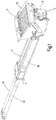
- thick matter pump has a material supply container 10 for receiving thick matter, such as liquid concrete.
- the liquid concrete is conveyed via a pipe bend 12 in an only indicated conveying line 14. This is done by means of two delivery cylinders 16,17, with the front side Mouth openings 18,19 are connected to one passage opening 18 ', 19' in the container wall 20 and their delivery piston 22,23 alternately perform a filling stroke and a delivery stroke.
- Inside the material feed container 10 there is a diverter 24, via which the delivery cylinders 16, 17 are alternately connectable to the container interior 21 and the delivery line 14.
- the diverter 24 is pivotable via a hydraulic drive mechanism in each case in its desired position with respect to the mouth openings 18,19.
- the delivery pistons 22,23 are moved by means of hydraulic cylinder-piston units 26,27, of which in Fig. 1 only the cylinders are indicated schematically.
- the diverter 24 has an opening in the direction of the orifices 18,19, designed as arcuate curved slot 28 inlet opening whose width corresponds to the diameter and the length of the outer distance of the mouth openings 18,19 and each one in Pivoting direction over the outer edge of the inlet opening 28 protruding closure approach 30,31, the longitudinal extent corresponds to the distance between the mouth openings 18,19 approximately.
- a special feature of the invention is that the pipe switch has a bow-shaped elongated hole 28 exhibiting metallic ring member 32 and a between the ring member 32 and an output side connected to the feed line pivot pipe 34 arranged cushion member 36.
- the padding element 36 has a long hole 28 in the ring member 32 comprehensive slot-shaped opening 38.
- the ring member 32 is axially movable relative to the pivot tube 34 and is under the action of the delivery pressure generated in the delivery stroke in the transfer tube 34 via the ring member 32 against the inner surface of the container wall 20 pressed.
- the container wall 20 carries on its the inner surface facing the ring member 32 a with the passage openings 18 ', 19' and provided with a bearing bore 40 for the bearing pin 42 replaceable metallic wear plate 20 '.
- the ring member 32 has a pivot tube side arranged, adapted over its outer contour to the cushion member 36 step-shaped pocket 44 for receiving the cushion member 36.
- the ring member 32 is also limited to the slot 28 through a stepped inner pocket wall 46 whose height is smaller than the outer pocket edge 48.
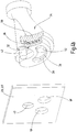
- At the cylinder-side end of the pivot tube 34 is an arcuately limited elevation 50, which is penetrated by the pivot tube channel 52 ( Fig. 3a ) and one of the pockets 44 in the ring element 32 corresponding outer contour ( Fig. 3b ).
- the cushion element 36 consists of a resilient, elastic or rubber-elastic material. A further improvement in the contact pressure effect can be achieved in that the cushioning element 36 contains a filling designed as an incompressible liquid.
- the inlet opening of the pipe switch or of the ring element is designed with its curved slot shape so that the two delivery cylinders 16,17 are short-circuited via their orifices 18,19 within the slot 28. If, in this position, both delivery cylinders 16, 17 carry out a delivery stroke with their delivery pistons 22, 23, a smooth, bumpless switching process can be ensured. In preparation for the switching operation, a pre-pressure can already be built up in the previously filled delivery cylinder while the closure attachment 30, 31 is being moved past the diverter 24. This gives a further improvement in terms of the continuous flow through the delivery line during the switching process. On the other hand, this means that the piston speeds and thus also the stroke duration during the filling stroke and the delivery stroke are different, since due to the described functional Special features for the filling stroke less time available than for the delivery stroke.
- the invention relates to a sludge pump with a material feed container 10 and two with end-side orifices 18,19 to a respective passage opening 18 ', 19' in the container wall 20 connected to the delivery cylinders 16,17.
- the delivery cylinders 16, 17 can be connected in alternation with the container interior 21 and a delivery line 14 by a pipe switch 24 arranged in the interior of the material delivery container 10, while their delivery pistons 22, 23 alternately perform a filling stroke and a delivery stroke.
- the diverter 24 has an opening in the direction of openings 18,19 facing, as a circular arc curved slot 28 formed inlet opening whose width corresponds to the diameter and its length to the outer distance of the mouth openings 18,19 and each one in the pivoting direction on the outer edge of the slot projecting closure approach 30,31, whose longitudinal extent corresponds to the distance between the mouth openings.
- the pipe switch 24 a the arcuate slot 28 exhibiting metallic ring member 32 and a connected between the ring member 32 and an output side to the feed line 14 Swivel tube 34 arranged, a the slot 28 comprehensive breakthrough 38 exhibiting cushion member 36, wherein the ring member 32 relative to the pivot tube 34 axially movable and under the action of the delivery pressure in the transfer tube 24 via the cushion member 36 against the inner surface of the container wall can be pressed.
Landscapes
- Engineering & Computer Science (AREA)
- Mechanical Engineering (AREA)
- General Engineering & Computer Science (AREA)
- Reciprocating Pumps (AREA)
- Details Of Reciprocating Pumps (AREA)
Description
- Die Erfindung bezieht sich auf eine Dickstoffpumpe mit einem Materialaufgabebehälter und zwei mit stirnseitigen Mündungsöffnungen an je eine Durchtrittsöffnung in der Behälterwand angeschlossenen Förderzylindern, die durch eine im Inneren des Materialaufgabebehälters angeordnete Rohrweiche abwechselnd mit dem Behälterinneren und einer Förderleitung verbindbar sind und deren Förderkolben abwechselnd einen Füllhub und einen Förderhub ausführen. Es ist dabei bekannt, dass die Rohrweiche eine in Richtung Mündungsöffnungen weisende, als kreisbogenförmig gekrümmtes Langloch ausgebildete Einlassöffnung aufweist, deren Breite dem Durchmesser und deren Länge dem Außenabstand der Mündungsöffnungen entspricht und die je einen in Schwenkrichtung über den Außenrand der Einlassöffnung überstehenden Verschlussansatz aufweist, dessen Längserstreckung dem Abstand zwischen den Mündungsöffnungen entspricht (
DE-195 03 986 A1 ). - Die bekannte Dickstoffpumpe zeichnet sich vor allem dadurch aus, dass die als gebogenes Langloch ausgebildete Einlassöffnung und die beiden Verschlussansätze der Rohrweiche gewährleisten dass während des Schwenk- bzw. Umschaltvorgangs der Rohrweiche zumindest zeitweise ein Kurzschluss der beiden Förderzylinder hergestellt ist. Mit diesen Maßnahmen wird erreicht, dass während des Umschaltvorgangs der Rohrweiche die beiden Förderzylinder zeitweise vom Inneren des Materialaufgabebehälters getrennt und unter gemeinsamer Verbindung mit der Förderleitung miteinander kurzgeschlossen werden können, so dass der eine Förderkolben seinen Förderhub noch beenden und gleichzeitig der andere Förderkolben mit seinem Förderhub bereits beginnen kann. Der den Förderhub beendende Förderkolben wird seinen anschließenden Füllhub erst ausführen, wenn der Kurzschluss zwischen den beiden Mündungsöffnungen wieder aufgehoben und der zugehörige Förderzylinder mit dem Behälterinneren verbunden ist. Für eine sichere Funktion ist es notwendig, dass die Rohrweiche sowohl während des Förderbetriebs als auch während des Umschaltbetriebs im Bereich der Mündungsöffnungen zuverlässig gegenüber der Behälterwand abgedichtet ist. Die bekannte Dickstoffpumpe der eingangs angegebenen Art lässt in dichtungstechnischer Hinsicht aber zu wünschen übrig.
- Ausgehend hiervon liegt der Erfindung die Aufgabe zugrunde, die bekannte Dickstoffpumpe der eingangs angegebenen Art dahingehend zu verbessern, dass sowohl im stationären als auch im bewegten Zustand der Rohrweiche eine ausreichende Abdichtung im Bereich der Rohrweichen-Behälterwandtrennstelle gewährleistet ist.
- Zur Lösung dieser Aufgabe wird die im Patentanspruch 1 angegebene Merkmalskombination vorgeschlagen. Vorteilhafte Ausgestaltungen und Weiterbildungen der Erfindung ergeben sich aus den abhängigen Ansprüchen.
- Die erfindungsgemäße Lösung besteht im Wesentlichen darin, dass die Rohrweiche ein das bogenförmige Langloch aufweisendes metallisches Ringelement sowie ein zwischen dem Ringelement und einem ausgangsseitig mit der Förderleitung verbundenen Schwenkrohr angeordnetes, einen das Langloch umfassenden Durchbruch aufweisendes Polsterelement aufweist, wobei das Ringelement relativ zum Schwenkrohr begrenzt axial beweglich und unter der Einwirkung des Förderdrucks in der Rohrweiche über das Polsterelement gegen die Innenfläche der Behälterwand anpressbar ist. Mit den erfindungsgemäßen Maßnahmen wird erreicht, dass die Dichtwirkung nicht zur statisch in der Endlagenstellung der Rohrweiche, sondern auch während der Drehbewegung der Rohrweiche aufrechterhalten bleibt. Die Rohrweiche wird damit in allen Schalt- bzw. Betriebszuständen zuverlässig gegenüber dem Behälterinneren abgedichtet. Dies gilt auch für den Bereich der Verschlussansätze, da das Polsterelement in diese hineinreicht und dort eine vom Rohrinneren her kommende Anpresswirkung erzeugt. Dabei ist zu berücksichtigen, dass die Verschlussansätze beim Umschaltvorgang zu Beginn eines Förderhubs das Vorverdichten des Dickstoffmaterials ermöglichen. Erfindungsgemäß weist das Polsterelement eine unkreisförmige flächige Querschnittsform auf. Das vorzugsweise gummielastische Material verhält sich nahezu inkompressibel, ähnlich wie eine Flüssigkeit, die den hydraulischen Druck gleichmäßig in alle Richtungen überträgt. Dies bedeutet, dass sich der Druck des Förderguts vom Inneren der Rohrweiche aus im Idealfall gleichförmig über das Polsterelement fortpflanzt, und zwar bis in die Verschlussansätze hinein. Dadurch wird das metallische Ringelement an die Innenfläche der Behälterwand gedrückt, obwohl nur die Einlasskontur des Polsterelements mit dem druckführenden Fördermedium in Kontakt steht. Eine weitere Verbesserung in dieser Hinsicht kann dadurch erzielt werden, dass innerhalb des Polsterelements eine Art Fluid- oder Geltasche vorgesehen wird, über die der Druck noch besser übertragen werden kann.
- Gemäß einer weiteren vorteilhaften Ausgestaltung der Erfindung trägt die Behälterwand an ihrer dem Ringelement zugewandten Innenfläche eine mit den Mündungsöffnungen versehene austauschbare Verschleißplatte. Diese lässt sich im Verschleißfall relativ einfach austauschen. Außerdem kann hierfür ein gegenüber dem Materialbehälter verschleißfesterer und daher teurerer Werkstoff verwendet werden.
- Eine weitere vorteilhafte Ausgestaltung der Erfindung sieht vor, dass das Ringelement eine schwenkrohrseitig angeordnete, über ihre Außenkontur an das Polsterelement angepasste, stufenförmig eingeformte Tasche zur Aufnahme des Polsterelements aufweist. Eine weitere Verbesserung in dieser Hinsicht wird erzielt, wenn das Ringelement auch zum Langloch hin durch eine stufenförmige Taschenwand begrenzt ist, deren Höhe kleiner als der äußere Taschenrand ist. Mit diesen Maßnahmen wird erreicht, dass das Polsterelement sicher zwischen Schwenkrohr und Ringelement eingebettet ist und auch beim Auftreten eines Saugdrucks, wie er beispielsweise bei einem Spülvorgang auftritt, nicht aus seiner Tasche herausgezogen wird.
- Eine weitere Verbesserung der Positionierung des Ringelements auf dem Schwenkrohr wird dadurch erzielt, dass am zylinderseitigen Ende des Schwenkrohrs eine bogenförmig begrenzte, von einem Schwenkrohrkanal durchdrungene Erhöhung angeordnet ist, die eine der Tasche in dem Ringelement entsprechende Außenkontur aufweist.
- Im Folgenden wird die Erfindung anhand eines in der Zeichnung in schematischer Weise dargestellten Ausführungsbeispiels näher erläutert. Es zeigen
- Fig. 1
- eine schaubildliche Darstellung einer Zweizylinder-Dickstoffpumpe;
- Fig. 2
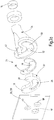
- eine Prinzipdarstellung der wesentlichen Teile der Dickstoffpumpe in einer schaubildlichen Explosionsdarstellung;
- Fig. 3a
- und b zwei schaubildliche Explosionsdarstellungen der Rohrweiche mit Verschleißplatte von verschiedenen Seiten her gesehen;
- Fig. 4a
- die Rohrweiche mit Verschleißplatte im Zusammenbauzustand der Rohrweiche in einer Darstellung entsprechend
Fig. 3a ; - Fig. 4b
- eine Darstellung entsprechend
Fig. 4a mit teilweise aufgebrochener Rohrweiche; - Fig. 5a
- bis c eine abgewandte Ausführungsform des Ringelements mit Polsterelement in einer Draufsicht, einer Schnittdarstellung und einer schaubildlichen Explosionsdarstellung.
- Die in
Fig. 1 dargestellte Dickstoffpumpe weist einen Materialaufgabebehälter 10 zur Aufnahme von Dickstoffen, wie Flüssigbeton auf. Der Flüssigbeton wird über einen Rohrkrümmer 12 in eine nur angedeutete Förderleitung 14 gefördert. Dies geschieht mittels zweier Förderzylinder 16,17, die mit stirnseitigen Mündungsöffnungen 18,19 an je eine Durchtrittsöffnung 18',19' in der Behälterwand 20 angeschlossen sind und deren Förderkolben 22,23 abwechselnd einen Füllhub und einen Förderhub ausführen. Im Inneren des Materialaufgabebehälters 10 befindet sich eine Rohrweiche 24, über welche die Förderzylinder 16,17 abwechselnd mit dem Behälterinneren 21 und der Förderleitung 14 verbindbar sind. Die Rohrweiche 24 ist dabei über einen hydraulischen Antriebsmechanismus jeweils in seine gewünschte Stellung bezüglich der Mündungsöffnungen 18,19 verschwenkbar. Die Förderkolben 22,23 werden mittels hydraulischer Zylinder-Kolbeneinheiten 26,27 bewegt, von denen inFig. 1 nur die Zylinder schematisch angedeutet sind. Wie weiter unten noch näher erläutert wird, weist die Rohrweiche 24 eine in Richtung Mündungsöffnungen 18,19 weisende, als kreisbogenförmig gekrümmtes Langloch 28 ausgebildete Einlassöffnung auf, deren Breite dem Durchmesser und deren Länge dem Außenabstand der Mündungsöffnungen 18,19 entspricht und die je einen in Schwenkrichtung über den Außenrand der Einlassöffnung 28 überstehenden Verschlussansatz 30,31 aufweist, dessen Längserstreckung dem Abstand zwischen den Mündungsöffnungen 18,19 etwa entspricht. - Eine Besonderheit der Erfindung besteht darin, dass die Rohrweiche ein das bogenförmige Langloch 28 aufweisendes metallisches Ringelement 32 sowie ein zwischen dem Ringelement 32 und einem ausgangsseitig mit der Förderleitung verbundenen Schwenkrohr 34 angeordnetes Polsterelement 36 aufweist. Das Polsterelement 36 weist einen das Langloch 28 im Ringelement 32 umfassenden langlochförmigen Durchbruch 38 auf. Das Ringelement 32 ist dabei relativ zum Schwenkrohr 34 axial beweglich und ist unter der Einwirkung des beim Förderhub erzeugten Förderdrucks in der Rohrweiche 34 über das Ringelement 32 gegen die Innenfläche der Behälterwand 20 anpressbar. Die Behälterwand 20 trägt an ihrer dem Ringelement 32 zugewandten Innenfläche eine mit den Durchtrittsöffnungen 18',19' und mit einer Lagerbohrung 40 für den Lagerbolzen 42 versehene austauschbare metallische Verschleißplatte 20'.
- Wie aus
Fig. 5a bis c zu ersehen ist, weist das Ringelement 32 eine schwenkrohrseitig angeordnete, über ihre Außenkontur an das Polsterelement 36 angepasste stufenförmig eingeformte Tasche 44 zur Aufnahme des Polsterelements 36 auf. Bei diesem Ausführungsbeispiel ist das Ringelement 32 auch zum Langloch 28 hin durch eine stufenförmige innere Taschenwand 46 begrenzt, deren Höhe kleiner als der äußere Taschenrand 48 ist. Am zylinderseitigen Ende des Schwenkrohrs 34 befindet sich eine bogenförmig begrenzte Erhöhung 50, die vom Schwenkrohrkanal 52 durchdrungen ist (Fig. 3a ) und die eine der Tasche 44 in dem Ringelement 32 entsprechende Außenkontur aufweist (Fig. 3b ). Mit diesen Maßnahmen wird die Axialführung des Ringelements 32 auf dem Schwenkrohr 34 verbessert und stabilisiert. - Um eine zuverlässige Druckübertragung zu gewährleisten, besteht das Polsterelement 36 aus einem nachgiebigen, elastischen oder gummielastischen Material. Eine weitere Verbesserung der Anpresswirkung kann dadurch erzielt werden, dass das Polsterelement 36 eine als inkompressible Flüssigkeit ausgebildete Füllung enthält.
- Die Einlassöffnung der Rohrweiche bzw. des Ringelements ist mit ihrer gebogenen Langlochgestalt so konzipiert, dass die beiden Förderzylinder 16,17 über ihre Mündungsöffnungen 18,19 innerhalb des Langlochs 28 kurzgeschlossen sind. Wenn in dieser Stellung beide Förderzylinder 16,17 mit ihren Förderkolben 22,23 einen Förderhub ausführen, kann ein glatter stoßfreier Umschaltvorgang gewährleistet werden. Zur Vorbereitung des Umschaltvorgangs kann in den zuvor gefüllten Förderzylinder während des Überfahrens des Verschlussansatzes 30,31 an der Rohrweiche 24 bereits ein Vordruck aufgebaut werden. Damit erhält man eine weitere Verbesserung hinsichtlich der kontinuierlichen Durchströmung der Förderleitung auch während des Umschaltvorgangs. Andererseits bedeutet dies, dass die Kolbengeschwindigkeiten und damit auch die Hubdauer während des Füllhubs und des Förderhubs unterschiedlich sind, da aufgrund der beschriebenen funktionellen Besonderheiten für den Füllhub weniger Zeit zur Verfügung steht als für den Förderhub.
- Zusammenfassend ist folgendes festzuhalten: Die Erfindung bezieht sich auf eine Dickstoffpumpe mit einem Materialaufgabebehälter 10 und zwei mit stirnseitigen Mündungsöffnungen 18,19 an je eine Durchtrittsöffnung 18',19' in der Behälterwand 20 angeschlossenen Förderzylindern 16,17. Die Förderzylinder 16,17 sind durch eine im Inneren des Materialaufgabebehälters 10 angeordnete Rohrweiche 24 abwechselnd mit dem Behälterinneren 21 und einer Förderleitung 14 verbindbar, während deren Förderkolben 22,23 abwechselnd einen Füllhub und einen Förderhub ausführen. Die Rohrweiche 24 weist eine in Richtung Mündungsöffnungen 18,19 weisende, als kreisbogenförmig gekrümmtes Langloch 28 ausgebildete Einlassöffnung auf, deren Breite dem Durchmesser und deren Länge dem Außenabstand der Mündungsöffnungen 18,19 entspricht und die je einen in Schwenkrichtung über den Außenrand des Langlochs überstehenden Verschlussansatz 30,31 aufweist, dessen Längserstreckung dem Abstand zwischen den Mündungsöffnungen entspricht. Um eine sichere Abdichtung der Trennstelle zwischen der Rohrweiche 24 und der Behälterwand 20 zu gewährleisten, wird gemäß der Erfindung vorgeschlagen, dass die Rohrweiche 24 ein das bogenförmige Langloch 28 aufweisendes metallisches Ringelement 32 sowie ein zwischen dem Ringelement 32 und einem ausgangsseitig mit der Förderleitung 14 verbundenen Schwenkrohr 34 angeordnetes, einen das Langloch 28 umfassenden Durchbruch 38 aufweisendes Polsterelement 36 aufweist, wobei das Ringelement 32 relativ zum Schwenkrohr 34 axial beweglich und unter der Einwirkung des Förderdrucks in der Rohrweiche 24 über das Polsterelement 36 gegen die Innenfläche der Behälterwand anpressbar ist.
-
- 10
- Materialaufgabebehälter
- 12
- Rohrkrümmer
- 14
- Förderleitung
- 16,17
- Förderzylinder
- 18,19
- Mündungsöffnungen
- 18', 19'
- Durchtrittsöffnungen
- 20
- Behälterwand
- 20'
- Verschleißplatte
- 21
- Behälterinneres
- 22,23
- Förderkolben
- 24
- Rohrweiche
- 26,27
- Zylinder-Kolbeneinheiten
- 28
- Langloch
- 30,31
- Verschlussansatz
- 32
- Ringelement
- 34
- Schwenkrohr
- 36
- Polsterelement
- 38
- Durchbruch
- 40
- Lagerbohrung
- 42
- Lagerbolzen
- 44
- Tasche
- 46
- Taschenwand
- 48
- Taschenrand
- 50
- Erhöhung
- 52
- Schwenkrohrkanal
Claims (8)
- Dickstoffpumpe mit einem Materialaufgabebehälter (10) und zwei mit stirnseitigen Mündungsöffnungen (18,19) an je eine Durchtrittsöffnung (18',19') in der Behälterwand angeschlossenen Förderzylindern (16,17), die durch eine im Inneren des Materialaufgabebehälters (10) angeordnete Rohrweiche (24) abwechselnd mit dem Behälterinneren (21) und einer Förderleitung (14) verbindbar sind, und deren Förderkolben (22,23) abwechselnd einen Füllhub und einen Förderhub ausführen, wobei die Rohrweiche (24) eine in Richtung Mündungsöffnungen (18,19) weisende, als kreisbogenförmig gekrümmtes Langloch (28) ausgebildete Einlassöffnung aufweist, deren Breite dem Durchmesser und deren Länge dem Außenabstand der Durchtrittsöffnungen (18',19') entspricht und die je einen in Schwenkrichtung über den Außenrand des Langlochs (28) überstehenden Verschlussansatz (30,31) aufweist, dadurch gekennzeichnet, dass die Rohrweiche (24) ein das bogenförmige Langloch (28) aufweisendes metallisches Ringelement (32) sowie ein zwischen dem Ringelement (32) und einem ausgangsseitig mit der Förderleitung (14) verbundenen Schwenkrohr (34) angeordnetes, einen das Langloch (28) umfassenden Durchbruch (38) aufweisendes Polsterelement (36) aufweist, wobei das Ringelement (32) relativ zum Schwenkrohr (34) axial beweglich und unter der Einwirkung des Förderdrucks in der Rohrweiche (24) über das Polsterelement (36) gegen die Innenfläche der Behälterwand (20) anpressbar ist.
- Dickstoffpumpe nach Anspruch 1, dadurch gekennzeichnet, dass die Behälterwand (20) an ihrer dem Ringelement (32) zugewandten Innenfläche eine mit den Durchtrittsöffnungen (18',19') versehene austauschbare Verschleißplatte (20') trägt.
- Dickstoffpumpe nach Anspruch 1 oder 2, dadurch gekennzeichnet, dass das Ringelement (32) eine schwenkrohrseitig angeordnete, über ihre Außenkontur an das Polsterelement (36) angepasste, unter Bildung eines äußeren Taschenrands (48) stufenförmig eingeformte Tasche (44) zur Aufnahme des Polsterelements (36) aufweist.
- Dickstoffpumpe nach Anspruch 3, dadurch gekennzeichnet, dass das Ringelement (32) auch zum Langloch (28) hin durch eine stufenförmige Taschenwand (46) begrenzt ist, deren Höhe kleiner als der äußere Taschenrand (48) ist.
- Dickstoffpumpe nach Anspruch 3 oder 4, dadurch gekennzeichnet, dass am zylinderseitigen Ende des Schwenkrohrs (34) eine bogenförmig begrenzte, von einem Schwenkrohrkanal (52) durchdrungene Erhöhung (50) angeordnet ist, die eine der Tasche (44) in dem Ringelement (32) entsprechende Außenkontur aufweist.
- Dickstoffpumpe nach einem der Ansprüche 1 bis 5, dadurch gekennzeichnet, dass das Polsterelement (36) aus einem nachgiebigen oder elastischen Material besteht.
- Dickstoffpumpe nach einem der Ansprüche 1 bis 6, dadurch gekennzeichnet, dass das Polsterelement (36) zumindest teilweise aus einem gummielastischen Material besteht.
- Dickstoffpumpe nach einem der Ansprüche 1 bis 7, dadurch gekennzeichnet, dass das Polsterelement (36) eine als inkompressible Flüssigkeit ausgebildete Füllung enthält.
Applications Claiming Priority (2)
| Application Number | Priority Date | Filing Date | Title |
|---|---|---|---|
| DE102013215990.0A DE102013215990A1 (de) | 2013-08-13 | 2013-08-13 | Zweizylinder-Dickstoffpumpe mit Rohrweiche |
| PCT/EP2014/058291 WO2015022088A1 (de) | 2013-08-13 | 2014-04-24 | Zweizylinder-dickstoffpumpe mit rohrweiche |
Publications (2)
| Publication Number | Publication Date |
|---|---|
| EP3033523A1 EP3033523A1 (de) | 2016-06-22 |
| EP3033523B1 true EP3033523B1 (de) | 2017-08-23 |
Family
ID=50543602
Family Applications (1)
| Application Number | Title | Priority Date | Filing Date |
|---|---|---|---|
| EP14719011.0A Active EP3033523B1 (de) | 2013-08-13 | 2014-04-24 | Zweizylinder-dickstoffpumpe mit rohrweiche |
Country Status (7)
| Country | Link |
|---|---|
| US (1) | US20160160851A1 (de) |
| EP (1) | EP3033523B1 (de) |
| JP (1) | JP2016528433A (de) |
| KR (1) | KR20160041910A (de) |
| CN (1) | CN105683569A (de) |
| DE (1) | DE102013215990A1 (de) |
| WO (1) | WO2015022088A1 (de) |
Families Citing this family (2)
| Publication number | Priority date | Publication date | Assignee | Title |
|---|---|---|---|---|
| EP3282125A1 (de) * | 2016-08-11 | 2018-02-14 | Putzmeister Engineering GmbH | Dickstoffventil |
| CN110195466B (zh) * | 2019-04-24 | 2021-07-13 | 湖南睿弓机械科技有限公司 | 清淤机械及其液压系统 |
Family Cites Families (20)
| Publication number | Priority date | Publication date | Assignee | Title |
|---|---|---|---|---|
| US3663129A (en) * | 1970-09-18 | 1972-05-16 | Leon A Antosh | Concrete pump |
| US3989420A (en) * | 1974-05-15 | 1976-11-02 | J. I. Case Company | Concrete pumping apparatus |
| DE2415276C2 (de) * | 1974-03-29 | 1976-11-11 | Friedrich Schwing | Pumpe zum Fördern von Dickstoffen, insbesondere Beton |
| US3963385A (en) * | 1975-05-05 | 1976-06-15 | Caban Angel M | Valve assembly for concrete pumps |
| DE2829181A1 (de) * | 1978-07-03 | 1980-01-17 | Scheele Maschf W | Rohrweiche fuer eine betonpumpe |
| DE3153268C2 (en) * | 1981-01-31 | 1988-01-28 | Friedrich Wilh. Schwing Gmbh, 4690 Herne, De | Two-cylinder viscous-material pump, preferably concrete pump |
| JPS6063079U (ja) * | 1983-10-07 | 1985-05-02 | 合資会社 八代石油 | コンクリ−トポンプの吐出口と分配管の間隙をシ−ルするリング |
| JPS60175780A (ja) * | 1984-02-23 | 1985-09-09 | Kyokuto Kaihatsu Kogyo Co Ltd | コンクリ−トポンプにおける吸送部の切換装置 |
| DE3419832A1 (de) * | 1984-05-26 | 1985-11-28 | Karl Dipl.-Ing. 7000 Stuttgart Schlecht | Rohrweiche einer dickstoff, insbesondere beton foerdernden doppelkolbenpumpe |
| DE3430193A1 (de) * | 1984-08-16 | 1986-02-27 | Linnhoff & Thesenfitz Maschinen- und Anlagenbau GmbH, 8754 Großostheim | Schwenkrohrsystem fuer betonpumpen |
| US5037275A (en) * | 1987-06-27 | 1991-08-06 | Karl Schlecht | Pipe junction switch for two-cylinder thick-material pump |
| DE3824466A1 (de) * | 1988-07-19 | 1990-01-25 | Putzmeister Maschf | Mehrzylinder-dickstoffpumpe |
| US5302094A (en) * | 1988-07-19 | 1994-04-12 | Putzmeister-Werk Maschinenfabrik Gmbh | Tube switch for a double-cylinder sludge pump |
| US5180294A (en) * | 1992-03-04 | 1993-01-19 | Confloat Consulting Ltd. | Concrete pump having pressurized seal for swing tube |
| DE19503986A1 (de) * | 1995-02-07 | 1996-08-08 | Hudelmaier Ulrike | Verfahren und Vorrichtung zum Fördern von Beton oder anderen Dickstoffen |
| US6857861B2 (en) * | 2002-05-15 | 2005-02-22 | Kennametal Inc. | Ring for concrete pump |
| KR20040057014A (ko) * | 2002-12-24 | 2004-07-01 | 한락수 | 콘크리트 펌프용 접동 구조물 및 그 제작방법 |
| DE10343802B4 (de) * | 2003-09-22 | 2007-12-06 | Schwing Gmbh | Kolben-Dickstoffpumpe mit kontinuierlichem Förderstrom |
| WO2007111689A2 (en) * | 2005-11-08 | 2007-10-04 | Good Earth Tools, Inc. | Sealing rings for abrasive slurry pumps |
| CN101718265B (zh) * | 2009-12-16 | 2012-10-10 | 三一重工股份有限公司 | 泵送设备的密封组件、分配阀总成、泵送设备及控制方法 |
-
2013
- 2013-08-13 DE DE102013215990.0A patent/DE102013215990A1/de not_active Withdrawn
-
2014
- 2014-04-24 EP EP14719011.0A patent/EP3033523B1/de active Active
- 2014-04-24 JP JP2016533842A patent/JP2016528433A/ja active Pending
- 2014-04-24 CN CN201480045266.6A patent/CN105683569A/zh active Pending
- 2014-04-24 KR KR1020167002999A patent/KR20160041910A/ko not_active Application Discontinuation
- 2014-04-24 WO PCT/EP2014/058291 patent/WO2015022088A1/de active Application Filing
-
2016
- 2016-02-12 US US15/042,202 patent/US20160160851A1/en not_active Abandoned
Non-Patent Citations (1)
| Title |
|---|
| None * |
Also Published As
| Publication number | Publication date |
|---|---|
| DE102013215990A1 (de) | 2015-02-19 |
| WO2015022088A1 (de) | 2015-02-19 |
| US20160160851A1 (en) | 2016-06-09 |
| CN105683569A (zh) | 2016-06-15 |
| JP2016528433A (ja) | 2016-09-15 |
| KR20160041910A (ko) | 2016-04-18 |
| EP3033523A1 (de) | 2016-06-22 |
Similar Documents
| Publication | Publication Date | Title |
|---|---|---|
| EP0825348B1 (de) | Druckverstärker für Fluide, insbesondere für Hydraulikflüssigkeiten | |
| DE102009005318B3 (de) | Verfahren zur Förderung breiiger Massen und Pumpvorrichtung zur Förderung breiiger Massen | |
| DE1498394A1 (de) | Abgabevorrichtung | |
| DE102009036663B4 (de) | Innenhochdruckumformwerkzeug und ein Verfahren zum Betreiben dessen | |
| LU84030A1 (de) | Verfahren und vorrichtung zum abgeben von viskosen konzentraten veraenderlicher viskositaet in genau dosierbaren mengen von variablem volumen | |
| EP1982104B1 (de) | Hydraulische vorrichtung mit schmierpumpe | |
| DE2447054A1 (de) | Dreiwege-verteiler fuer betondoppelpumpen | |
| DE202009002951U1 (de) | Schmierstoffverteiler | |
| EP3033523B1 (de) | Zweizylinder-dickstoffpumpe mit rohrweiche | |
| EP2025978A2 (de) | Wegeventil für eine Scheibenreinigungsvorrichtung in einem Kraftfahrzeug | |
| DE102012224317B4 (de) | Steckpumpe | |
| EP0315750B1 (de) | Dickstoff-Pumpe | |
| DE4136097C1 (de) | ||
| DE3034467A1 (de) | Hydraulische vorrichtung zum ueberwachen einer verbindung | |
| EP0036945A2 (de) | Vorrichtung zum Fördern von fliessfähigen Medien | |
| DE2943967C2 (de) | ||
| DE102006038389B4 (de) | Schmiermittel-Dosierpumpe und Dosierverfahren mit zwei gegeneinander beweglichen Kolben | |
| DE947040C (de) | Hydraulisch angetriebene Kolbenpumpe zur Foerderung von dickfluessigen, breiigen Massen, z. B. Beton | |
| DE102017126651B4 (de) | Pumpeinrichtung mit über einem gemeinsamen Antrieb gekoppelten Pumpen | |
| DE3710013A1 (de) | Membranverdraengerpumpe, insbesondere fuer reibende, korrosive fluessigkeiten mit in suspension befindlichen teilchen od. dgl. | |
| DE19927070B4 (de) | Hydraulische Presse | |
| DE2542392A1 (de) | Hochdruckmembranpumpe | |
| EP3695119B1 (de) | Kolbenpumpe mit zwangssteuerungselement | |
| EP3497329B1 (de) | Dickstoffventil | |
| DE102004022226A1 (de) | Dosierverteiler mit verbesserter Dosiergenauigkeit durch Leckageleitung und Verfahren zum Verteilen und Dosieren eines Verteilermediums |
Legal Events
| Date | Code | Title | Description |
|---|---|---|---|
| PUAI | Public reference made under article 153(3) epc to a published international application that has entered the european phase |
Free format text: ORIGINAL CODE: 0009012 |
|
| 17P | Request for examination filed |
Effective date: 20160308 |
|
| AK | Designated contracting states |
Kind code of ref document: A1 Designated state(s): AL AT BE BG CH CY CZ DE DK EE ES FI FR GB GR HR HU IE IS IT LI LT LU LV MC MK MT NL NO PL PT RO RS SE SI SK SM TR |
|
| AX | Request for extension of the european patent |
Extension state: BA ME |
|
| DAX | Request for extension of the european patent (deleted) | ||
| GRAP | Despatch of communication of intention to grant a patent |
Free format text: ORIGINAL CODE: EPIDOSNIGR1 |
|
| INTG | Intention to grant announced |
Effective date: 20170509 |
|
| GRAS | Grant fee paid |
Free format text: ORIGINAL CODE: EPIDOSNIGR3 |
|
| GRAA | (expected) grant |
Free format text: ORIGINAL CODE: 0009210 |
|
| AK | Designated contracting states |
Kind code of ref document: B1 Designated state(s): AL AT BE BG CH CY CZ DE DK EE ES FI FR GB GR HR HU IE IS IT LI LT LU LV MC MK MT NL NO PL PT RO RS SE SI SK SM TR |
|
| REG | Reference to a national code |
Ref country code: GB Ref legal event code: FG4D Free format text: NOT ENGLISH |
|
| REG | Reference to a national code |
Ref country code: CH Ref legal event code: EP |
|
| REG | Reference to a national code |
Ref country code: AT Ref legal event code: REF Ref document number: 921640 Country of ref document: AT Kind code of ref document: T Effective date: 20170915 |
|
| REG | Reference to a national code |
Ref country code: IE Ref legal event code: FG4D Free format text: LANGUAGE OF EP DOCUMENT: GERMAN |
|
| REG | Reference to a national code |
Ref country code: DE Ref legal event code: R096 Ref document number: 502014005162 Country of ref document: DE |
|
| REG | Reference to a national code |
Ref country code: NL Ref legal event code: MP Effective date: 20170823 |
|
| REG | Reference to a national code |
Ref country code: LT Ref legal event code: MG4D |
|
| PG25 | Lapsed in a contracting state [announced via postgrant information from national office to epo] |
Ref country code: NL Free format text: LAPSE BECAUSE OF FAILURE TO SUBMIT A TRANSLATION OF THE DESCRIPTION OR TO PAY THE FEE WITHIN THE PRESCRIBED TIME-LIMIT Effective date: 20170823 Ref country code: HR Free format text: LAPSE BECAUSE OF FAILURE TO SUBMIT A TRANSLATION OF THE DESCRIPTION OR TO PAY THE FEE WITHIN THE PRESCRIBED TIME-LIMIT Effective date: 20170823 Ref country code: LT Free format text: LAPSE BECAUSE OF FAILURE TO SUBMIT A TRANSLATION OF THE DESCRIPTION OR TO PAY THE FEE WITHIN THE PRESCRIBED TIME-LIMIT Effective date: 20170823 Ref country code: FI Free format text: LAPSE BECAUSE OF FAILURE TO SUBMIT A TRANSLATION OF THE DESCRIPTION OR TO PAY THE FEE WITHIN THE PRESCRIBED TIME-LIMIT Effective date: 20170823 Ref country code: NO Free format text: LAPSE BECAUSE OF FAILURE TO SUBMIT A TRANSLATION OF THE DESCRIPTION OR TO PAY THE FEE WITHIN THE PRESCRIBED TIME-LIMIT Effective date: 20171123 Ref country code: SE Free format text: LAPSE BECAUSE OF FAILURE TO SUBMIT A TRANSLATION OF THE DESCRIPTION OR TO PAY THE FEE WITHIN THE PRESCRIBED TIME-LIMIT Effective date: 20170823 |
|
| PG25 | Lapsed in a contracting state [announced via postgrant information from national office to epo] |
Ref country code: RS Free format text: LAPSE BECAUSE OF FAILURE TO SUBMIT A TRANSLATION OF THE DESCRIPTION OR TO PAY THE FEE WITHIN THE PRESCRIBED TIME-LIMIT Effective date: 20170823 Ref country code: PL Free format text: LAPSE BECAUSE OF FAILURE TO SUBMIT A TRANSLATION OF THE DESCRIPTION OR TO PAY THE FEE WITHIN THE PRESCRIBED TIME-LIMIT Effective date: 20170823 Ref country code: LV Free format text: LAPSE BECAUSE OF FAILURE TO SUBMIT A TRANSLATION OF THE DESCRIPTION OR TO PAY THE FEE WITHIN THE PRESCRIBED TIME-LIMIT Effective date: 20170823 Ref country code: BG Free format text: LAPSE BECAUSE OF FAILURE TO SUBMIT A TRANSLATION OF THE DESCRIPTION OR TO PAY THE FEE WITHIN THE PRESCRIBED TIME-LIMIT Effective date: 20171123 Ref country code: ES Free format text: LAPSE BECAUSE OF FAILURE TO SUBMIT A TRANSLATION OF THE DESCRIPTION OR TO PAY THE FEE WITHIN THE PRESCRIBED TIME-LIMIT Effective date: 20170823 Ref country code: IS Free format text: LAPSE BECAUSE OF FAILURE TO SUBMIT A TRANSLATION OF THE DESCRIPTION OR TO PAY THE FEE WITHIN THE PRESCRIBED TIME-LIMIT Effective date: 20171223 Ref country code: GR Free format text: LAPSE BECAUSE OF FAILURE TO SUBMIT A TRANSLATION OF THE DESCRIPTION OR TO PAY THE FEE WITHIN THE PRESCRIBED TIME-LIMIT Effective date: 20171124 |
|
| PG25 | Lapsed in a contracting state [announced via postgrant information from national office to epo] |
Ref country code: CZ Free format text: LAPSE BECAUSE OF FAILURE TO SUBMIT A TRANSLATION OF THE DESCRIPTION OR TO PAY THE FEE WITHIN THE PRESCRIBED TIME-LIMIT Effective date: 20170823 Ref country code: RO Free format text: LAPSE BECAUSE OF FAILURE TO SUBMIT A TRANSLATION OF THE DESCRIPTION OR TO PAY THE FEE WITHIN THE PRESCRIBED TIME-LIMIT Effective date: 20170823 Ref country code: DK Free format text: LAPSE BECAUSE OF FAILURE TO SUBMIT A TRANSLATION OF THE DESCRIPTION OR TO PAY THE FEE WITHIN THE PRESCRIBED TIME-LIMIT Effective date: 20170823 |
|
| REG | Reference to a national code |
Ref country code: DE Ref legal event code: R097 Ref document number: 502014005162 Country of ref document: DE |
|
| PG25 | Lapsed in a contracting state [announced via postgrant information from national office to epo] |
Ref country code: SM Free format text: LAPSE BECAUSE OF FAILURE TO SUBMIT A TRANSLATION OF THE DESCRIPTION OR TO PAY THE FEE WITHIN THE PRESCRIBED TIME-LIMIT Effective date: 20170823 Ref country code: EE Free format text: LAPSE BECAUSE OF FAILURE TO SUBMIT A TRANSLATION OF THE DESCRIPTION OR TO PAY THE FEE WITHIN THE PRESCRIBED TIME-LIMIT Effective date: 20170823 Ref country code: SK Free format text: LAPSE BECAUSE OF FAILURE TO SUBMIT A TRANSLATION OF THE DESCRIPTION OR TO PAY THE FEE WITHIN THE PRESCRIBED TIME-LIMIT Effective date: 20170823 |
|
| PLBE | No opposition filed within time limit |
Free format text: ORIGINAL CODE: 0009261 |
|
| STAA | Information on the status of an ep patent application or granted ep patent |
Free format text: STATUS: NO OPPOSITION FILED WITHIN TIME LIMIT |
|
| 26N | No opposition filed |
Effective date: 20180524 |
|
| PG25 | Lapsed in a contracting state [announced via postgrant information from national office to epo] |
Ref country code: SI Free format text: LAPSE BECAUSE OF FAILURE TO SUBMIT A TRANSLATION OF THE DESCRIPTION OR TO PAY THE FEE WITHIN THE PRESCRIBED TIME-LIMIT Effective date: 20170823 |
|
| PG25 | Lapsed in a contracting state [announced via postgrant information from national office to epo] |
Ref country code: MT Free format text: LAPSE BECAUSE OF FAILURE TO SUBMIT A TRANSLATION OF THE DESCRIPTION OR TO PAY THE FEE WITHIN THE PRESCRIBED TIME-LIMIT Effective date: 20170823 |
|
| PG25 | Lapsed in a contracting state [announced via postgrant information from national office to epo] |
Ref country code: MC Free format text: LAPSE BECAUSE OF FAILURE TO SUBMIT A TRANSLATION OF THE DESCRIPTION OR TO PAY THE FEE WITHIN THE PRESCRIBED TIME-LIMIT Effective date: 20170823 |
|
| REG | Reference to a national code |
Ref country code: CH Ref legal event code: PL |
|
| REG | Reference to a national code |
Ref country code: BE Ref legal event code: MM Effective date: 20180430 |
|
| GBPC | Gb: european patent ceased through non-payment of renewal fee |
Effective date: 20180424 |
|
| REG | Reference to a national code |
Ref country code: IE Ref legal event code: MM4A |
|
| PG25 | Lapsed in a contracting state [announced via postgrant information from national office to epo] |
Ref country code: LU Free format text: LAPSE BECAUSE OF NON-PAYMENT OF DUE FEES Effective date: 20180424 |
|
| PG25 | Lapsed in a contracting state [announced via postgrant information from national office to epo] |
Ref country code: BE Free format text: LAPSE BECAUSE OF NON-PAYMENT OF DUE FEES Effective date: 20180430 Ref country code: GB Free format text: LAPSE BECAUSE OF NON-PAYMENT OF DUE FEES Effective date: 20180424 Ref country code: LI Free format text: LAPSE BECAUSE OF NON-PAYMENT OF DUE FEES Effective date: 20180430 Ref country code: CH Free format text: LAPSE BECAUSE OF NON-PAYMENT OF DUE FEES Effective date: 20180430 |
|
| PG25 | Lapsed in a contracting state [announced via postgrant information from national office to epo] |
Ref country code: FR Free format text: LAPSE BECAUSE OF NON-PAYMENT OF DUE FEES Effective date: 20180430 Ref country code: IE Free format text: LAPSE BECAUSE OF NON-PAYMENT OF DUE FEES Effective date: 20180424 |
|
| PG25 | Lapsed in a contracting state [announced via postgrant information from national office to epo] |
Ref country code: PT Free format text: LAPSE BECAUSE OF FAILURE TO SUBMIT A TRANSLATION OF THE DESCRIPTION OR TO PAY THE FEE WITHIN THE PRESCRIBED TIME-LIMIT Effective date: 20170823 |
|
| PG25 | Lapsed in a contracting state [announced via postgrant information from national office to epo] |
Ref country code: CY Free format text: LAPSE BECAUSE OF FAILURE TO SUBMIT A TRANSLATION OF THE DESCRIPTION OR TO PAY THE FEE WITHIN THE PRESCRIBED TIME-LIMIT Effective date: 20170823 Ref country code: HU Free format text: LAPSE BECAUSE OF FAILURE TO SUBMIT A TRANSLATION OF THE DESCRIPTION OR TO PAY THE FEE WITHIN THE PRESCRIBED TIME-LIMIT; INVALID AB INITIO Effective date: 20140424 Ref country code: MK Free format text: LAPSE BECAUSE OF NON-PAYMENT OF DUE FEES Effective date: 20170823 |
|
| PG25 | Lapsed in a contracting state [announced via postgrant information from national office to epo] |
Ref country code: AL Free format text: LAPSE BECAUSE OF FAILURE TO SUBMIT A TRANSLATION OF THE DESCRIPTION OR TO PAY THE FEE WITHIN THE PRESCRIBED TIME-LIMIT Effective date: 20170823 |
|
| PGFP | Annual fee paid to national office [announced via postgrant information from national office to epo] |
Ref country code: DE Payment date: 20200424 Year of fee payment: 7 Ref country code: TR Payment date: 20200424 Year of fee payment: 7 |
|
| REG | Reference to a national code |
Ref country code: AT Ref legal event code: MM01 Ref document number: 921640 Country of ref document: AT Kind code of ref document: T Effective date: 20190424 |
|
| PGFP | Annual fee paid to national office [announced via postgrant information from national office to epo] |
Ref country code: IT Payment date: 20200423 Year of fee payment: 7 |
|
| PG25 | Lapsed in a contracting state [announced via postgrant information from national office to epo] |
Ref country code: AT Free format text: LAPSE BECAUSE OF NON-PAYMENT OF DUE FEES Effective date: 20190424 |
|
| REG | Reference to a national code |
Ref country code: DE Ref legal event code: R119 Ref document number: 502014005162 Country of ref document: DE |
|
| PG25 | Lapsed in a contracting state [announced via postgrant information from national office to epo] |
Ref country code: DE Free format text: LAPSE BECAUSE OF NON-PAYMENT OF DUE FEES Effective date: 20211103 |
|
| PG25 | Lapsed in a contracting state [announced via postgrant information from national office to epo] |
Ref country code: IT Free format text: LAPSE BECAUSE OF NON-PAYMENT OF DUE FEES Effective date: 20200424 |